EP3154144A1 - Improvements in or relating to direct current distance protection controllers - Google Patents
Improvements in or relating to direct current distance protection controllers Download PDFInfo
- Publication number
- EP3154144A1 EP3154144A1 EP15275208.5A EP15275208A EP3154144A1 EP 3154144 A1 EP3154144 A1 EP 3154144A1 EP 15275208 A EP15275208 A EP 15275208A EP 3154144 A1 EP3154144 A1 EP 3154144A1
- Authority
- EP
- European Patent Office
- Prior art keywords
- fault component
- voltage
- power transmission
- protection controller
- voltage value
- Prior art date
- Legal status (The legal status is an assumption and is not a legal conclusion. Google has not performed a legal analysis and makes no representation as to the accuracy of the status listed.)
- Granted
Links
Images

Classifications
-
- H—ELECTRICITY
- H02—GENERATION; CONVERSION OR DISTRIBUTION OF ELECTRIC POWER
- H02H—EMERGENCY PROTECTIVE CIRCUIT ARRANGEMENTS
- H02H7/00—Emergency protective circuit arrangements specially adapted for specific types of electric machines or apparatus or for sectionalised protection of cable or line systems, and effecting automatic switching in the event of an undesired change from normal working conditions
- H02H7/26—Sectionalised protection of cable or line systems, e.g. for disconnecting a section on which a short-circuit, earth fault, or arc discharge has occured
- H02H7/268—Sectionalised protection of cable or line systems, e.g. for disconnecting a section on which a short-circuit, earth fault, or arc discharge has occured for DC systems
-
- G—PHYSICS
- G01—MEASURING; TESTING
- G01R—MEASURING ELECTRIC VARIABLES; MEASURING MAGNETIC VARIABLES
- G01R31/00—Arrangements for testing electric properties; Arrangements for locating electric faults; Arrangements for electrical testing characterised by what is being tested not provided for elsewhere
- G01R31/08—Locating faults in cables, transmission lines, or networks
- G01R31/081—Locating faults in cables, transmission lines, or networks according to type of conductors
-
- H—ELECTRICITY
- H02—GENERATION; CONVERSION OR DISTRIBUTION OF ELECTRIC POWER
- H02H—EMERGENCY PROTECTIVE CIRCUIT ARRANGEMENTS
- H02H3/00—Emergency protective circuit arrangements for automatic disconnection directly responsive to an undesired change from normal electric working condition with or without subsequent reconnection ; integrated protection
- H02H3/38—Emergency protective circuit arrangements for automatic disconnection directly responsive to an undesired change from normal electric working condition with or without subsequent reconnection ; integrated protection responsive to both voltage and current; responsive to phase angle between voltage and current
-
- H—ELECTRICITY
- H02—GENERATION; CONVERSION OR DISTRIBUTION OF ELECTRIC POWER
- H02H—EMERGENCY PROTECTIVE CIRCUIT ARRANGEMENTS
- H02H3/00—Emergency protective circuit arrangements for automatic disconnection directly responsive to an undesired change from normal electric working condition with or without subsequent reconnection ; integrated protection
- H02H3/40—Emergency protective circuit arrangements for automatic disconnection directly responsive to an undesired change from normal electric working condition with or without subsequent reconnection ; integrated protection responsive to ratio of voltage and current
-
- H—ELECTRICITY
- H02—GENERATION; CONVERSION OR DISTRIBUTION OF ELECTRIC POWER
- H02H—EMERGENCY PROTECTIVE CIRCUIT ARRANGEMENTS
- H02H1/00—Details of emergency protective circuit arrangements
- H02H1/0038—Details of emergency protective circuit arrangements concerning the connection of the detecting means, e.g. for reducing their number
- H02H1/0053—Means for storing the measured quantities during a predetermined time
-
- H—ELECTRICITY
- H02—GENERATION; CONVERSION OR DISTRIBUTION OF ELECTRIC POWER
- H02H—EMERGENCY PROTECTIVE CIRCUIT ARRANGEMENTS
- H02H3/00—Emergency protective circuit arrangements for automatic disconnection directly responsive to an undesired change from normal electric working condition with or without subsequent reconnection ; integrated protection
- H02H3/02—Details
- H02H3/05—Details with means for increasing reliability, e.g. redundancy arrangements
-
- H—ELECTRICITY
- H02—GENERATION; CONVERSION OR DISTRIBUTION OF ELECTRIC POWER
- H02H—EMERGENCY PROTECTIVE CIRCUIT ARRANGEMENTS
- H02H7/00—Emergency protective circuit arrangements specially adapted for specific types of electric machines or apparatus or for sectionalised protection of cable or line systems, and effecting automatic switching in the event of an undesired change from normal working conditions
- H02H7/26—Sectionalised protection of cable or line systems, e.g. for disconnecting a section on which a short-circuit, earth fault, or arc discharge has occured
- H02H7/265—Sectionalised protection of cable or line systems, e.g. for disconnecting a section on which a short-circuit, earth fault, or arc discharge has occured making use of travelling wave theory
Definitions
- This invention relates to a direct current (DC) distance protection controller and a DC electrical power network including at least one such controller.
- DC direct current
- DC electrical power networks such as DC grids, typically include a plurality of terminals each of which may be operatively associated with a power converter to interconnect the DC power transmission network with a respective alternating current (AC) network.
- AC alternating current
- Respective pairs of terminals are interconnected by a DC power transmission conduit, such as a transmission line or cable.
- Protection devices such as circuit breakers and relays, can be operated by one or more protection controllers in the event of a fault so as to protect the DC electrical power network.
- a DC distance protection controller for identifying a fault within a protection zone extending between a first terminal with which the protection controller is in use operatively associated and a set point along a DC power transmission conduit lying between the first terminal and a second terminal within a DC electrical power network, the protection controller being programmed to:
- a controller that isolates fault component voltage and current values from respective corresponding measured voltage and current values offers an initial indication of whether a fault has arisen and allows a subsequent assessment of the nature of the fault, i.e. whether the fault has arisen within the protection zone of the associated DC power transmission conduit.
- a fault component operating voltage at the set point facilitates a determination of the nature of the fault, i.e. by way of a comparison with a historical measured voltage value, in a manner that is reliable and repeatable.
- the reliance solely on measured voltage and current values obtained at the first terminal and calculated fault component operating voltages based on such measured voltage and current values allows the DC distance protection controller of the invention to identify a fault within the protection zone without the need to rely on remote measurements from one or more other parts of a given DC electrical power network.
- Such a controller therefore avoids the need for complex and unreliable communication links with the said remote parts of the DC electrical power network, as well as the need to compensate for the communication time delay associated with such remote communications.
- the reliance of the controller on a comparison of a given calculated fault component operating voltage with an already measured, historical measured voltage value allows the controller to provide ultra-high speed, i.e. within 1 millisecond, identification of a fault within the protection zone, thus allowing protective measures, e.g. the operation of an associated protection device, to also be carried out very quickly, i.e. within 5 milliseconds.
- the controller is programmed to isolate a fault component voltage value and fault component current value in respect of each sampled pair of measured voltage and current values by applying a filter to the measured voltage value and the measured current value of each said sampled pair.
- Such a step reliably and repeatedly removes all other elements from each of the measured voltage and current values so as to leave only the required corresponding fault component voltage and current values.
- controller is programmed to compare the magnitudes of respective calculated fault component operating voltages and historical voltage values.
- Such a comparison can be readily carried out by a controller in the form of, e.g. a programmable microcontroller or the like.
- the controller is programmed to compare a given calculated fault component operating voltage with a corresponding historical voltage value derived from a historical measured voltage value obtained a predetermined period of time before the time at which the sampled pair on which the said given fault component operating voltage is based was obtained.
- the predetermined period of time is at least 5 milliseconds.
- the foregoing features assist the protection controller in accurately identifying a fault within the protection zone by helping to ensure that the historical measured voltage value with which a given calculated fault component operating voltage is compared is untainted by a fault component which might otherwise adversely affect the outcome of such a comparison.
- the set point is spaced along the DC power transmission conduit from the first terminal by between 80% and 95% of the total length of the said transmission conduit.
- Locating the set point along the DC power transmission conduit in the aforementioned manner defines a protection zone which provides protection for the vast majority of the DC power transmission conduit, i.e. up to 95% of the said transmission conduit.
- the protection controller may be programmed to calculate a given fault component operating voltage from the corresponding isolated pair of fault component voltage and current values using one of the following models of the DC power transmission conduit:
- Each of the foregoing models provides a desired degree of accuracy, in terms of the manner in which it approximates the performance characteristics of the DC power transmission conduit, according to the overall length of the said transmission conduit.
- the protection controller is additionally programmed to operate an associated protection device upon receipt of an external trip signal.
- Such a configuration advantageously extends the functionality of the protection controller of the invention in circumstances where modest communication between, e.g. remote terminals in a DC electrical power network, is possible.
- a DC electrical power network comprising at least one DC distance protection controller according to any preceding claim.
- Such a DC electrical power network shares the benefits associated with the or each DC distance protection controller included therein.
- a DC distance protection controller according to a first embodiment of the invention is designated generally by reference numeral 10.
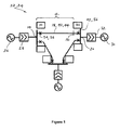
- the first protection controller 10 is arranged to identify a fault within a protection zone 12 that extends between a first terminal 14 with which the first protection controller 10 is, in use, operatively associated, and a set point 16 along a DC power transmission conduit 18.
- the DC power transmission conduit 18 lies between the aforementioned first terminal 14 and a second terminal 20, with both the first and second terminals 14, 20 forming a part of a DC electrical power network 22 that has the form of a DC grid 24, as shown schematically in Figure 1 .
- the set point 16 is spaced from the first terminal 14 by between 80% and 95%, and preferably 90% and 95%, of the total length of the first DC power transmission conduit 18, such that the set point 16 lies a distance D Set from the first terminal 14.
- the first terminal 14 has a first AC network 26 connected thereto via a first power converter 28 while the second terminal 20 has a second AC network 30 connected thereto via a second power converter 32.
- the first protection controller 10 is also operatively associated, in use, with a first protection device 34, which in the embodiment shown is a circuit breaker 36, although other types of protection device such as a relay are also possible.
- the first protection device 34 i.e. circuit breaker 36, is operable to protect the protection zone 12 within the first DC power transmission conduit 18, and more particularly is operable to isolate the protection zone 12 from the first terminal 14 and hence from the first AC network 26 connected thereto.
- the first protection controller 10 is programmed to:
- the first protection controller 10 periodically obtains measured voltage values u m and measured current values i m of the DC power transmission conduit 18 via a measurement apparatus (not shown) which is operatively associated with the first terminal 14 and is able selectively to measure the current and voltage of the DC power transmission conduit 18 at the said first terminal 14.
- the first DC power transmission conduit 18 is defined by a first transmission line 42, and more particularly by a first bi-polar transmission line 44, i.e. a transmission line incorporating two conductors (not shown) operating at different polarities.
- the first DC power transmission conduit 18 may instead be defined by a first underground transmission cable which may or may not be bi-polar and could be mono-polar, i.e. could incorporate a single conductor operating at a single polarity.
- the first DC power transmission conduit 18 could also be defined by a mono-polar transmission line.
- the measurement apparatus periodically takes measured samples of a positive-pole voltage u mP of a first conductor of the bi-polar transmission line 44 operating at a positive polarity and measured samples of a negative-pole voltage u mN of a second conductor of the bi-polar transmission line 44 operating at a negative polarity.
- Each such measured sample is taken with respect to ground in each instance and at a respective busbar of a double busbar (not shown) which defines the first terminal 14.
- the measurement apparatus similarly periodically takes measured samples, at the first terminal 14, of a positive-pole current i mP flowing in the first conductor between the first and second terminals 14, 20 and of a negative-pole current i mN flowing in the second conductor between the first and second terminals 14, 20.
- the first protection controller 10 includes a phase-mode transformation block 46, as shown in Figure 2 .
- the first protection controller 10 need not be programmed to carry out the aforementioned phase-mode transformation, and is able to make use instead of measured voltage and current values u m , i m obtained directly from the measurement apparatus. Accordingly the first protection controller 10 in such embodiments may omit the phase-mode transformation block 46 mentioned above.
- the first protection controller 10 obtains respective sampled pairs 38 of measured voltage and current values u m , i m , i.e. equivalent positive-mode voltage and current values u m+ , i m+ .
- the first protection controller 10 isolates in respect of each sampled pair 38 of measured voltage and current values u m , i m respective voltage and current fault components. More particularly, the protection controller 10 isolates a fault component voltage value ⁇ u m from each corresponding measured voltage value u m and isolates a fault component current value ⁇ i m from each corresponding measured current value i m , and thereby defines respective corresponding isolated pairs 40 of fault component voltage and current values ⁇ u m , ⁇ i m .
- the protection controller 10 is programmed to carry out such isolation by applying a filter, and more particularly a high pass filter, and to that end the protection controller 10 includes a filter block 48.
- the first protection controller 10 is then programmed to calculate from each isolated pair 40 of fault component voltage and current values ⁇ u m , ⁇ i m a fault component operating voltage ⁇ u op of the DC power transmission conduit 18 at the set point 16 therealong.
- the protection controller 10 is so programmed to calculate the respective fault component operating voltages ⁇ u op using a resistance-inductance model of the DC power transmission conduit 18.
- a resistance-inductance model of the DC power transmission conduit 18 is particularly suitable, i.e. provides a desired degree of accuracy, if the first bi-polar transmission line 44 is relatively short, e.g. less than approximately 100km (or less than approximately 30km if the DC power transmission conduit 18 is instead defined by an underground transmission cable).
- Each of the resistance and inductance values R set , L set mentioned above can be established from technical data on the DC power transmission conduit 18, e.g. as provided by the operator of the DC electrical power network 22, and the known distance D Set of the set point 16 from the first terminal 14.
- the first protection controller 10 may instead be programmed to calculate respective fault component operating voltages ⁇ u op at the set point 16 along the DC power transmission conduit 18 by using either a distributed parameter line model of the DC power transmission conduit 18 or a frequency dependent distributed parameter line model of the DC power transmission conduit 18.
- the main equations set out above may again be utilized but the following parameters may instead be calculated:
- having the first protection controller 10 programmed to calculate respective fault component operating voltages ⁇ u op using a distributed parameter line model of the DC power transmission conduit 18 is helpful for a longer transmission line 42, i.e. a line between approximately 100km and 200km, (or between approximately 30km and 80km if the DC power transmission conduit 18 is defined by an underground cable), since it is able to take account of any propagation time delay of a voltage waveform travelling within the line.
- the aforesaid a k and b k coefficients can be calculated by Carlson's equation from technical data on the DC power transmission conduit 18, e.g. as provided by the operator of the DC electrical power network 22.
- Having a first protection controller 10 programmed to calculate respective fault component operating voltages ⁇ u op using a frequency dependent distributed parameter line model of the DC power transmission conduit 18 is helpful for extra-long transmission lines 42, i.e. a line more than approximately 200km long (or more than 80km long if the DC power transmission conduit 18 is defined by an underground cable), since it is able to take into account frequency-dependent parameters (such as, for example, the skin effect) which distort to a considerable extent the waveform of traveling waves in transmission lines of such length.
- frequency-dependent parameters such as, for example, the skin effect
- the protection controller 10 is programmed to compare a given calculated fault component operating voltage ⁇ u op , and more particularly each calculated fault component operating voltage ⁇ u op , with a historical voltage value u h that is derived from a historical measured voltage value u m' from an earlier sampled pair 38 of measured voltage and current values u m , i m .
- the historical voltage value u h is identical to, and thereby derived directly from, the said historical measured voltage value u m' , i.e. an earlier measured voltage value u m' obtained at the first terminal 14.
- the historical voltage value u h may instead be given by a historical calculated voltage value which has been calculated for some other point along the DC power transmission conduit 18.
- the historical calculated voltage value is calculated from, i.e. derived from, corresponding historical measured voltage and current values obtained (as an earlier sampled pair (38)) at the first terminal 14.
- the protection controller 10 includes a comparison block 52 that is programmed to compare the magnitude of a given fault component operating voltage ⁇ u op with the magnitude of the said historical voltage u h .
- RMS root mean square
- the protection controller 10 is programmed to compare the magnitude of a given calculated fault component operating voltage ⁇ u op ⁇ with the magnitude of a corresponding historical voltage value ⁇ u h ⁇ derived from, i.e. identical to, a historical measured voltage value u m' which was obtained, i.e. measured, a predetermined period of time before the time at which the sampled pair 38 of measured voltage and current values u m , i m from which the said magnitude of a given calculated fault component operating voltage ⁇ u op ⁇ is derived were obtained, i.e. measured.
- the predetermined period of time is at least 5 milliseconds and is, in the embodiment shown, 10 milliseconds.
- the predetermined period may be less than or more than 10 milliseconds.
- the first protection controller 10 identifies that there is a fault within the protection zone 12.
- the measured voltage value at the first terminal 14 remains equal to a normal operating voltage of the associated DC power transmission conduit 18 such that, in turn, respective historical measured voltage values u m' similarly remain equal to the normal operating voltage.
- respective historical voltage values u h being derived directly from the historical measured voltage values u m' , also remain equal to the normal operating voltage.
- the magnitude of a given historical voltage value ⁇ u h ⁇ i.e. the magnitude of the normal expected operating voltage of the DC power transmission conduit 18, is greater than the magnitude of the corresponding calculated fault component operating voltage ⁇ u op ⁇ , and so the protection controller 10 provides no indication that a fault has arisen.
- the protection controller 10 operates the first protection device 34, e.g. by issuing a trip command 58, to protect, i.e. isolate, the protection zone 12 from the first AC network 26.
- the measured voltage value at the first terminal 14 remains equal to a normal operating voltage of the associated DC power transmission conduit 18 such that respective historical voltage values u h similarly remain equal to the normal operating voltage.
- the magnitude of the calculated fault component operating voltage ⁇ u op ⁇ at the set point 16 is zero, such that the protection controller 10 does not indicate that a fault has arisen.
- the first protection controller 10 operates the first protection device 34 upon receipt of an external trip signal 62, e.g. from a second protection controller 70 which is operatively associated with the second terminal 20 at the other end of the first DC power transmission conduit 18.
- the second protection controller 70 is very similar to the first protection controller 10 and is programmed to operate in essentially the same manner with respect to a further set point (not shown) similarly spaced from the second terminal 20 to define a second protection zone which overlaps with the first protection zone 12.
- the second protection controller 70 is additionally arranged to operate a second protection device 72 in the form of a further circuit breaker 36 to isolate the second protection zone from the second terminal 20 and the second AC network 30 connected therewith.
- the first and second protection controllers 10; 70 and associated first and second protection devices 34; 72 therefore together provide overlapping protection for the first DC power transmission conduit 18.
Landscapes
- Physics & Mathematics (AREA)
- General Physics & Mathematics (AREA)
- Direct Current Feeding And Distribution (AREA)
- Emergency Protection Circuit Devices (AREA)
- Supply And Distribution Of Alternating Current (AREA)
- Protection Of Static Devices (AREA)
- Locating Faults (AREA)
Abstract
(i) periodically obtain as respective sampled pairs (38) a measured voltage value (um) and a measured current value (im) of the DC power transmission conduit (18) at the first terminal (14);
(ii) isolate in respect of each sampled pair (38), a fault component voltage value (Δum) from the corresponding measured voltage value (um) and a fault component current value (Δim) from the corresponding measured current value (im) to define a respective corresponding isolated pair (40);
(iii) calculate from each isolated pair (40) of fault component voltage and current values (Δum, Δim) a fault component operating voltage (Δuop) of the DC power transmission conduit (18) at the set point (16) along the DC power transmission conduit (18);
(iv) compare a given calculated fault component operating voltage (Δuop) with a historical voltage value (uh) derived from a historical measured voltage value (um') from an earlier sampled pair (38) of measured voltage and current values (um, im); and
(v) identify a fault (60) within the protection zone (12) when the given calculated fault component operating voltage (Δuop) is greater than the historical voltage value (um') with which it is compared.
Description
- This invention relates to a direct current (DC) distance protection controller and a DC electrical power network including at least one such controller.
- DC electrical power networks, such as DC grids, typically include a plurality of terminals each of which may be operatively associated with a power converter to interconnect the DC power transmission network with a respective alternating current (AC) network.
- Respective pairs of terminals are interconnected by a DC power transmission conduit, such as a transmission line or cable. Protection devices, such as circuit breakers and relays, can be operated by one or more protection controllers in the event of a fault so as to protect the DC electrical power network.
- According to a first aspect of the invention there is a provided a DC distance protection controller, for identifying a fault within a protection zone extending between a first terminal with which the protection controller is in use operatively associated and a set point along a DC power transmission conduit lying between the first terminal and a second terminal within a DC electrical power network, the protection controller being programmed to:
- (i) periodically obtain as respective sampled pairs a measured voltage value and a measured current value of the DC power transmission conduit at the first terminal;
- (ii) isolate in respect of each sampled pair, a fault component voltage value from the corresponding measured voltage value and a fault component current value from the corresponding measured current value to define a respective corresponding isolated pair;
- (iii) calculate from each isolated pair of fault component voltage and current values a fault component operating voltage of the DC power transmission conduit at the set point along the DC power transmission conduit;
- (iv) compare a given calculated fault component operating voltage with a historical voltage value derived from a historical measured voltage value from an earlier sampled pair of measured voltage and current values; and
- (v) identify a fault within the protection zone when the given calculated fault component operating voltage is greater than the historical voltage value with which it is compared.
- The provision of a controller that isolates fault component voltage and current values from respective corresponding measured voltage and current values offers an initial indication of whether a fault has arisen and allows a subsequent assessment of the nature of the fault, i.e. whether the fault has arisen within the protection zone of the associated DC power transmission conduit.
- Meanwhile, subsequently calculating from each isolated pair of fault component voltage and current values a fault component operating voltage at the set point facilitates a determination of the nature of the fault, i.e. by way of a comparison with a historical measured voltage value, in a manner that is reliable and repeatable.
- Moreover, the reliance solely on measured voltage and current values obtained at the first terminal and calculated fault component operating voltages based on such measured voltage and current values allows the DC distance protection controller of the invention to identify a fault within the protection zone without the need to rely on remote measurements from one or more other parts of a given DC electrical power network.
- Such a controller therefore avoids the need for complex and unreliable communication links with the said remote parts of the DC electrical power network, as well as the need to compensate for the communication time delay associated with such remote communications.
- In addition, the reliance of the controller on a comparison of a given calculated fault component operating voltage with an already measured, historical measured voltage value, allows the controller to provide ultra-high speed, i.e. within 1 millisecond, identification of a fault within the protection zone, thus allowing protective measures, e.g. the operation of an associated protection device, to also be carried out very quickly, i.e. within 5 milliseconds.
- Preferably the controller is programmed to isolate a fault component voltage value and fault component current value in respect of each sampled pair of measured voltage and current values by applying a filter to the measured voltage value and the measured current value of each said sampled pair.
- Such a step reliably and repeatedly removes all other elements from each of the measured voltage and current values so as to leave only the required corresponding fault component voltage and current values.
- Optionally the controller is programmed to compare the magnitudes of respective calculated fault component operating voltages and historical voltage values.
- Such a comparison can be readily carried out by a controller in the form of, e.g. a programmable microcontroller or the like.
- In a preferred embodiment of the invention the controller is programmed to compare a given calculated fault component operating voltage with a corresponding historical voltage value derived from a historical measured voltage value obtained a predetermined period of time before the time at which the sampled pair on which the said given fault component operating voltage is based was obtained.
- Preferably the predetermined period of time is at least 5 milliseconds.
- The foregoing features assist the protection controller in accurately identifying a fault within the protection zone by helping to ensure that the historical measured voltage value with which a given calculated fault component operating voltage is compared is untainted by a fault component which might otherwise adversely affect the outcome of such a comparison.
- In a preferred embodiment of the invention the set point is spaced along the DC power transmission conduit from the first terminal by between 80% and 95% of the total length of the said transmission conduit.
- Locating the set point along the DC power transmission conduit in the aforementioned manner defines a protection zone which provides protection for the vast majority of the DC power transmission conduit, i.e. up to 95% of the said transmission conduit.
- The protection controller may be programmed to calculate a given fault component operating voltage from the corresponding isolated pair of fault component voltage and current values using one of the following models of the DC power transmission conduit:
- a resistance-inductance model;
- a distributed parameter line model; and
- a frequency dependent distributed parameter line model.
- Each of the foregoing models provides a desired degree of accuracy, in terms of the manner in which it approximates the performance characteristics of the DC power transmission conduit, according to the overall length of the said transmission conduit.
- In another preferred embodiment of the invention the protection controller is additionally programmed to operate an associated protection device upon receipt of an external trip signal.
- Such a configuration advantageously extends the functionality of the protection controller of the invention in circumstances where modest communication between, e.g. remote terminals in a DC electrical power network, is possible.
- According to a second aspect of the invention there is provided a DC electrical power network comprising at least one DC distance protection controller according to any preceding claim.
- Such a DC electrical power network shares the benefits associated with the or each DC distance protection controller included therein.
- There now follows a brief description of preferred embodiments of the invention, by way of non-limiting examples, with reference being made to the following drawings in which:
-
Figure 1 shows a schematic view of a DC electrical power network including first and second DC distance protection controllers according to respective first and second embodiments of the invention; -
Figure 2 shows a schematic representation of the first protection controller shown inFigure 1 ; -
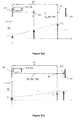
Figure 3(a) illustrates schematically operation of the first protection controller in the event of a first fault within a protection zone covered by the first protection controller; and -
Figure 3(b) illustrates schematically operation of the first protection controller in the event of a second fault outside the protection zone covered by the first protection controller. - A DC distance protection controller according to a first embodiment of the invention is designated generally by
reference numeral 10. - The
first protection controller 10 is arranged to identify a fault within aprotection zone 12 that extends between afirst terminal 14 with which thefirst protection controller 10 is, in use, operatively associated, and aset point 16 along a DC power transmission conduit 18. - The DC power transmission conduit 18 lies between the aforementioned
first terminal 14 and asecond terminal 20, with both the first andsecond terminals Figure 1 . Theset point 16 is spaced from thefirst terminal 14 by between 80% and 95%, and preferably 90% and 95%, of the total length of the first DC power transmission conduit 18, such that theset point 16 lies a distance DSet from thefirst terminal 14. Meanwhile thefirst terminal 14 has afirst AC network 26 connected thereto via afirst power converter 28 while thesecond terminal 20 has asecond AC network 30 connected thereto via asecond power converter 32. - The
first protection controller 10 is also operatively associated, in use, with a first protection device 34, which in the embodiment shown is a circuit breaker 36, although other types of protection device such as a relay are also possible. The first protection device 34, i.e. circuit breaker 36, is operable to protect theprotection zone 12 within the first DC power transmission conduit 18, and more particularly is operable to isolate theprotection zone 12 from thefirst terminal 14 and hence from thefirst AC network 26 connected thereto. - With reference to
Figure 2 , thefirst protection controller 10 is programmed to: - (i) periodically obtain as respective sampled pairs 38 a measured voltage value um and a measured current value im of the DC power transmission conduit 18 at the
first terminal 14; - (ii) isolate in respect of each sampled
pair 38, a fault component voltage value Δum from the corresponding measured voltage value um and a fault component current value Δim from the corresponding measured current value im to define a respective corresponding isolated pair 40; - (iii) calculate from each isolated pair 40 of fault component voltage and current values Δum, Δim a fault component operating voltage Δuop of the DC power transmission conduit 18 at the
set point 16 along the DC power transmission conduit 18; - (iv) compare a given calculated fault component operating voltage Δuop with a historical voltage value uh derived from a historical measured voltage value um' from an earlier sampled
pair 38 of measured voltage and current values um, im; and - (v) identify a fault within the
protection zone 12 when the given calculated fault component operating voltage Δuop is greater than the historical voltage value uh with which it is compared. - The
first protection controller 10 periodically obtains measured voltage values um and measured current values im of the DC power transmission conduit 18 via a measurement apparatus (not shown) which is operatively associated with thefirst terminal 14 and is able selectively to measure the current and voltage of the DC power transmission conduit 18 at the saidfirst terminal 14. - In the embodiment shown, the first DC power transmission conduit 18 is defined by a first transmission line 42, and more particularly by a first bi-polar transmission line 44, i.e. a transmission line incorporating two conductors (not shown) operating at different polarities. In other embodiments (not shown) the first DC power transmission conduit 18 may instead be defined by a first underground transmission cable which may or may not be bi-polar and could be mono-polar, i.e. could incorporate a single conductor operating at a single polarity. The first DC power transmission conduit 18 could also be defined by a mono-polar transmission line.
- With respect to the first bi-polar transmission line 44, the measurement apparatus periodically takes measured samples of a positive-pole voltage umP of a first conductor of the bi-polar transmission line 44 operating at a positive polarity and measured samples of a negative-pole voltage umN of a second conductor of the bi-polar transmission line 44 operating at a negative polarity. Each such measured sample is taken with respect to ground in each instance and at a respective busbar of a double busbar (not shown) which defines the
first terminal 14. - Meanwhile the measurement apparatus similarly periodically takes measured samples, at the
first terminal 14, of a positive-pole current imP flowing in the first conductor between the first andsecond terminals second terminals - The sampling period Ts adopted by the measurement apparatus may, by way of example, be given by:

- Since such positive and negative samples are taken it is necessary thereafter, in the embodiment shown, for the
first protection controller 10 to additionally calculate an equivalent to a directly measured voltage value um in the form of a positive-mode (which may also be known as an 'aerial' mode) voltage value um+, and also an equivalent to a directly measured current value im in the form of a positive-mode current value im+ according to the following phase-mode transformation:
where, - umP is the measured voltage of the positive polar conduit;
- umN is the measured voltage of the negative polar conduit;
- imP is the measured current of the positive polar conduit; and
- imN is the measured current of the negative polar conduit.
- In order to carry out the aforementioned phase-mode transformation the
first protection controller 10 includes a phase-mode transformation block 46, as shown inFigure 2 . - In embodiments of the invention operatively associated with a DC power transmission conduit 18 that is defined by a mono-polar transmission line or cable, the
first protection controller 10 need not be programmed to carry out the aforementioned phase-mode transformation, and is able to make use instead of measured voltage and current values um, im obtained directly from the measurement apparatus. Accordingly thefirst protection controller 10 in such embodiments may omit the phase-mode transformation block 46 mentioned above. - Accordingly, the
first protection controller 10 obtains respective sampledpairs 38 of measured voltage and current values um, im, i.e. equivalent positive-mode voltage and current values um+, im+. - Thereafter the
first protection controller 10 isolates in respect of each sampledpair 38 of measured voltage and current values um, im respective voltage and current fault components. More particularly, theprotection controller 10 isolates a fault component voltage value Δum from each corresponding measured voltage value um and isolates a fault component current value Δim from each corresponding measured current value im, and thereby defines respective corresponding isolated pairs 40 of fault component voltage and current values Δum, Δim. - The
protection controller 10 is programmed to carry out such isolation by applying a filter, and more particularly a high pass filter, and to that end theprotection controller 10 includes afilter block 48. Thefilter block 48 produces the aforementioned respective isolated pairs 40 of fault component voltage and current values Δum, Δim according to the following:
where,
M is the number of samples in the chosen window which is determined by the length of the chosen window over which samples are obtained. - By way of example the window may be 5 milliseconds, such that:

where,
Ts is the sampling period, e.g. 1/96000 seconds
whereby

- Different sampling periods and/or window lengths may, however, be used.
- The
first protection controller 10 is then programmed to calculate from each isolated pair 40 of fault component voltage and current values Δum, Δim a fault component operating voltage Δuop of the DC power transmission conduit 18 at theset point 16 therealong. - The
protection controller 10 is so programmed to calculate the respective fault component operating voltages Δuop using a resistance-inductance model of the DC power transmission conduit 18. Such a model is particularly suitable, i.e. provides a desired degree of accuracy, if the first bi-polar transmission line 44 is relatively short, e.g. less than approximately 100km (or less than approximately 30km if the DC power transmission conduit 18 is instead defined by an underground transmission cable). - The
first protection controller 10 includes a fault component operatingvoltage calculation block 50 which handles the calculation of each of the various fault component operating voltages Δuop, from the corresponding isolated pair 40 of fault component voltage and current values Δum, Δim, based on the differential equation,
which can be implemented by:
where, - Rset is the resistance of the section of DC power transmission conduit 18 from the
first terminal 14 to theset point 16 along the DC power transmission conduit 18; and - Lset is the inductance of the section of DC power transmission conduit 18 from the
first terminal 14 to theset point 16 along the DC power transmission conduit 18. - Each of the resistance and inductance values Rset, Lset mentioned above can be established from technical data on the DC power transmission conduit 18, e.g. as provided by the operator of the DC electrical power network 22, and the known distance DSet of the
set point 16 from thefirst terminal 14. - In other embodiments of the invention (not shown) the
first protection controller 10 may instead be programmed to calculate respective fault component operating voltages Δuop at theset point 16 along the DC power transmission conduit 18 by using either a distributed parameter line model of the DC power transmission conduit 18 or a frequency dependent distributed parameter line model of the DC power transmission conduit 18. - In embodiments in which the
protection controller 10 is programmed to calculate respective fault component operating voltages Δuop using a distributed parameter line model of the DC power transmission conduit 18, it is assumed that the parameters of the frequencies are the same as those of one representative frequency, e.g. 50Hz, or 100Hz, such that
where, - Δfm is the forward voltage travelling wave at the location of the first protection device 34, i.e. at the
first terminal 14; and - Δbm is the backward voltage travelling wave at the location of the first protection device 34, i.e. at the
first terminal 14 -

-

-

first terminal 14, to theset point 16 along the DC power transmission conduit 18 with Dset being the equivalent distance in km of theset point 16 from thefirst terminal 14; and -

first terminal 14, to theset point 16 along the DC power transmission conduit 18. - The performance values mentioned above can again be established from technical data provided by the operator of the DC electrical power network 22, and the known distance Dset of the
set point 16 from thefirst terminal 14. - As an alternative if the first transmission line 42, i.e. the first bi-polar transmission line 44, is not in distortion, the main equations set out above may again be utilized but the following parameters may instead be calculated:
-

- Tz = 0, i.e. the phase shift of the surge impedance is neglected;
-

first terminal 14, to theset point 16 along the DC power transmission conduit 18; and - Kp = exp(-RDset /Zc ), is the decaying factor from where the first protection device 34 is located, i.e. the
first terminal 14, to theset point 16 along the DC power transmission conduit 18, with R being the resistance per unit length (ohm/km) of the first transmission line 42. - Similarly these performance values can again be established from technical data provided by the operator of the DC electrical power network 22, and the known distance Dset of the
set point 16 from thefirst terminal 14. - In any event, having the
first protection controller 10 programmed to calculate respective fault component operating voltages Δuop using a distributed parameter line model of the DC power transmission conduit 18 is helpful for a longer transmission line 42, i.e. a line between approximately 100km and 200km, (or between approximately 30km and 80km if the DC power transmission conduit 18 is defined by an underground cable), since it is able to take account of any propagation time delay of a voltage waveform travelling within the line. - In further embodiments, in which the
first protection controller 10 is programmed to calculate respective fault component operating voltages Δuop using a frequency distributed parameter line model of the DC power transmission conduit 18, theprotection controller 10 first of all calculates a forward traveling wave Δfm(t) and a backward traveling wave Δbm(t) according to the following equations:

where, - Zc (t) is the surge impedance which is frequency-dependent, and which can be described in the frequency domain by

with - Zc0 being the constant part of the surge impedance; and
- ak and bk being coefficients of the surge impedance in frequency domain Zc(z)
- The aforesaid ak and bk coefficients can be calculated by Carlson's equation from technical data on the DC power transmission conduit 18, e.g. as provided by the operator of the DC electrical power network 22.
- Meanwhile the symbol * represents the mathematical operation of convolution, wherein it can be assumed that the surge impedance zc has 3 orders.
- The
protection controller 10 then secondly calculates the forward and backward traveling waves fop, bop at theset point 16 according to:

where, - TpSet is the minimum propagation time from where the first protection device 34 is located, i.e. the
first terminal 14, to theset point 16 along the DC power transmission conduit 18; - hset (t) is the propagation function for a traveling wave from where the first protection device 34 is located, i.e. from the
first terminal 14, to the to theset point 16 along the DC power transmission conduit 18, which can be described in the frequency domain by
with, - ck and dk being coefficients of the propagation function Hset(z).
- The foregoing ck and dk coefficients can again be calculated by Carlson's equation from technical data provided by the operator of the DC electrical power network 22.
- Finally the
protection controller 10 calculates the respective fault component operating voltages Δuop according to:
- Having a
first protection controller 10 programmed to calculate respective fault component operating voltages Δuop using a frequency dependent distributed parameter line model of the DC power transmission conduit 18 is helpful for extra-long transmission lines 42, i.e. a line more than approximately 200km long (or more than 80km long if the DC power transmission conduit 18 is defined by an underground cable), since it is able to take into account frequency-dependent parameters (such as, for example, the skin effect) which distort to a considerable extent the waveform of traveling waves in transmission lines of such length. - Meanwhile, returning to the embodiment shown, the
protection controller 10 is programmed to compare a given calculated fault component operating voltage Δuop, and more particularly each calculated fault component operating voltage Δuop, with a historical voltage value uh that is derived from a historical measured voltage value um' from an earlier sampledpair 38 of measured voltage and current values um, im. - In the embodiment shown the historical voltage value uh is identical to, and thereby derived directly from, the said historical measured voltage value um', i.e. an earlier measured voltage value um' obtained at the
first terminal 14. - In other embodiments of the invention, the historical voltage value uh may instead be given by a historical calculated voltage value which has been calculated for some other point along the DC power transmission conduit 18. In such circumstances the historical calculated voltage value is calculated from, i.e. derived from, corresponding historical measured voltage and current values obtained (as an earlier sampled pair (38)) at the
first terminal 14. - The
protection controller 10 includes acomparison block 52 that is programmed to compare the magnitude of a given fault component operating voltage Δuop with the magnitude of the said historical voltage uh. - In the embodiment shown the
protection controller 10 calculates each such magnitude ∥ ∥ using amagnitude calculation block 54 which determines a root mean square (RMS) value ∥Δuop∥, ∥uh∥ from each of the corresponding fault component operating voltage Δuop and the historical voltage value uh according to:
with, - W being the number of samples in the sample set, e.g. 48, i.e. as obtained by setting a window length of 0.5 milliseconds (to help ensure a fast response by the protection controller 10) with a sampling period of 1/96000 seconds.
- In other embodiments of the invention the
magnitude calculation block 54 may instead determine a magnitude ∥ ∥ in the form of a sum of the absolute value, i.e. as given by:
where, - W is again the number of samples in the sample set.
- In either case, the
protection controller 10 is programmed to compare the magnitude of a given calculated fault component operating voltage ∥Δuop∥ with the magnitude of a corresponding historical voltage value ∥uh∥ derived from, i.e. identical to, a historical measured voltage value um' which was obtained, i.e. measured, a predetermined period of time before the time at which the sampledpair 38 of measured voltage and current values um, im from which the said magnitude of a given calculated fault component operating voltage ∥Δuop∥ is derived were obtained, i.e. measured. - The predetermined period of time is at least 5 milliseconds and is, in the embodiment shown, 10 milliseconds. The predetermined period may be less than or more than 10 milliseconds.
- In any event, a practical way of ensuring that the historical measured voltage value um' from which the historical voltage value uh is derived was obtained 10 milliseconds before the voltage and current values um, im from which the fault component operating voltage Δuop it is to be compared with was obtained, is to introduce a delay in the utilisation of the historical voltage value uh. The
protection controller 10 achieves this by including adelay block 56 which holds up further use of the magnitude of the historical voltage value ∥uh∥ by the desired 10 milliseconds. - When the magnitude of the calculated fault component operating voltage ∥Δuop∥ is greater than the magnitude of the corresponding historical voltage value ∥uh∥, the
first protection controller 10 identifies that there is a fault within theprotection zone 12. - Such operation of the
first protection controller 10 in the event of afirst fault 60 arising within theprotection zone 12 covered by theprotection controller 10 is illustrated schematically inFigure 3(a) . - More particularly, before the
first fault 60 arises the measured voltage value at thefirst terminal 14 remains equal to a normal operating voltage of the associated DC power transmission conduit 18 such that, in turn, respective historical measured voltage values um' similarly remain equal to the normal operating voltage. Hence respective historical voltage values uh, being derived directly from the historical measured voltage values um', also remain equal to the normal operating voltage. There are no fault components in the measured voltage and current values obtained during this pre-fault period and so the magnitude of the calculated fault component operating voltage ∥Δuop∥ at theset point 16 is zero. - Accordingly, the magnitude of a given historical voltage value ∥uh∥, i.e. the magnitude of the normal expected operating voltage of the DC power transmission conduit 18, is greater than the magnitude of the corresponding calculated fault component operating voltage ∥Δuop∥, and so the
protection controller 10 provides no indication that a fault has arisen. - When the
first fault 60 arises a fault component appears in each of the measured voltage value um and the measured current value im at thefirst terminal 14, such that an isolated pair 40 of fault component voltage and current values Δum, Δim is output by thefilter block 48 of theprotection controller 10. Such an isolated pair 40 gives rise to a calculated fault component operating voltage Δuop which, as shown inFigure 3(a) , has a magnitude that is greater than the magnitude of the corresponding historical voltage value uh, i.e. the normal operating voltage of the DC transmission conduit 18 as measured 10 milliseconds earlier. Consequently theprotection controller 10 is able to identify that thefirst fault 62 has arisen within theprotection zone 12. - Thereafter the
protection controller 10 operates the first protection device 34, e.g. by issuing atrip command 58, to protect, i.e. isolate, theprotection zone 12 from thefirst AC network 26. - Operation of the
first protection controller 10 when asecond fault 64 arises in the DC power transmission conduit 18 at a point which lies outside theprotection zone 12, is illustrated schematically inFigure 3(b) . - Again, before the
first fault 60 arises the measured voltage value at thefirst terminal 14 remains equal to a normal operating voltage of the associated DC power transmission conduit 18 such that respective historical voltage values uh similarly remain equal to the normal operating voltage. There are no fault components in the measured voltage and current values, and so the magnitude of the calculated fault component operating voltage ∥Δuop∥ at theset point 16 is zero, such that theprotection controller 10 does not indicate that a fault has arisen. - When the
second fault 64 arises outside the protection zone 12 a fault component nevertheless appears in each of the measured voltage value um and the measured current value im at thefirst terminal 14, such that an isolated pair 40 of fault component voltage and current values Δum, Δim is again output by thefilter block 48 of theprotection controller 10. The calculated fault component operating voltage Δuop derived from the aforementioned isolated pair 40 does, however, have a magnitude that is less than the magnitude of the corresponding historical voltage value uh, i.e. the normal operating voltage of the DC transmission conduit 18 as measured 10 milliseconds earlier, as shown inFigure 3(b) . Consequently theprotection controller 10 is able to discern that thesecond fault 64 has arisen outside theprotection zone 12, and hence makes no indication that a fault has arisen. - In addition to the foregoing, the
first protection controller 10 operates the first protection device 34 upon receipt of anexternal trip signal 62, e.g. from asecond protection controller 70 which is operatively associated with thesecond terminal 20 at the other end of the first DC power transmission conduit 18. Thesecond protection controller 70 is very similar to thefirst protection controller 10 and is programmed to operate in essentially the same manner with respect to a further set point (not shown) similarly spaced from thesecond terminal 20 to define a second protection zone which overlaps with thefirst protection zone 12. - The
second protection controller 70 is additionally arranged to operate a second protection device 72 in the form of a further circuit breaker 36 to isolate the second protection zone from thesecond terminal 20 and thesecond AC network 30 connected therewith. The first andsecond protection controllers 10; 70 and associated first and second protection devices 34; 72 therefore together provide overlapping protection for the first DC power transmission conduit 18.

where,
Claims (9)
- A DC distance protection controller, for identifying a fault within a protection zone extending between a first terminal with which the protection controller is in use operatively associated and a set point along a DC power transmission conduit lying between the first terminal and a second terminal within a DC electrical power network, the protection controller being programmed to:(i) periodically obtain as respective sampled pairs a measured voltage value and a measured current value of the DC power transmission conduit at the first terminal;(ii) isolate in respect of each sampled pair, a fault component voltage value from the corresponding measured voltage value and a fault component current value from the corresponding measured current value to define a respective corresponding isolated pair;(iii) calculate from each isolated pair of fault component voltage and current values a fault component operating voltage of the DC power transmission conduit at the set point along the DC power transmission conduit;(iv) compare a given calculated fault component operating voltage with a historical voltage value derived from a historical measured voltage value from an earlier sampled pair of measured voltage and current values; and(v) identify a fault within the protection zone when the given calculated fault component operating voltage is greater than the historical voltage value with which it is compared.
- A DC distance protection controller according to Claim 1 programmed to isolate a fault component voltage value and a fault component current value in respect of each sampled pair of measured voltage and current values by applying a filter to the measured voltage value and the measured current value of each said sampled pair.
- A DC distance protection controller according to any proceeding claim programmed to compare the magnitudes of respective calculated fault component operating voltages and historical voltage values.
- A DC distance protection controller according to any preceding claim programmed to compare a given calculated fault component operating voltage with a corresponding historical voltage value derived from a historical measured voltage value obtained a predetermined period of time before the time at which the sampled pair on which the said given fault component operating voltage is based was obtained.
- A DC distance protection controller according to Claim 4 wherein the predetermined period of time is at least 5 milliseconds.
- A DC distance protection controller according to any preceding claim wherein the set point is spaced along the DC power transmission conduit from the first terminal by between 80% and 95% of the total length of the said transmission conduit.
- A DC distance protection controller according to any preceding claim programmed to calculate a given fault component operating voltage from the corresponding isolated pair of fault component voltage and current values using one of the following models of the DC power transmission conduit:a resistance-inductance model;a distributed parameter line model; anda frequency dependent distributed parameter line model.
- A DC distance protection controller according to any preceding claim additionally programmed to operate an associated protection device upon receipt of an external trip signal.
- A DC electrical power network comprising at least one DC distance protection controller according to any preceding claim.
Priority Applications (8)
| Application Number | Priority Date | Filing Date | Title |
|---|---|---|---|
| EP15275208.5A EP3154144B1 (en) | 2015-10-06 | 2015-10-06 | Improvements in or relating to direct current distance protection controllers |
| BR112018006859-4A BR112018006859B1 (en) | 2015-10-06 | 2016-09-29 | CONTINUOUS CURRENT DISTANCE PROTECTION CONTROLLER AND CONTINUOUS CURRENT ELECTRIC POWER NETWORK |
| US15/766,555 US11081879B2 (en) | 2015-10-06 | 2016-09-29 | Direct current distance protection controllers |
| CN201680058468.3A CN108141032B (en) | 2015-10-06 | 2016-09-29 | Improvements in or related to DC distance protection controllers |
| MX2018004260A MX372608B (en) | 2015-10-06 | 2016-09-29 | IMPROVEMENTS IN OR RELATED TO DIRECT CURRENT REMOTE PROTECTION CONTROLLERS |
| JP2018517511A JP6767478B2 (en) | 2015-10-06 | 2016-09-29 | Improvements to the DC distance protection controller or related improvements |
| PCT/EP2016/073305 WO2017060155A1 (en) | 2015-10-06 | 2016-09-29 | Improvements in or relating to direct current distance protection controllers |
| CA3000879A CA3000879C (en) | 2015-10-06 | 2016-09-29 | Improvements in or relating to direct current distance protection controllers |
Applications Claiming Priority (1)
| Application Number | Priority Date | Filing Date | Title |
|---|---|---|---|
| EP15275208.5A EP3154144B1 (en) | 2015-10-06 | 2015-10-06 | Improvements in or relating to direct current distance protection controllers |
Publications (2)
| Publication Number | Publication Date |
|---|---|
| EP3154144A1 true EP3154144A1 (en) | 2017-04-12 |
| EP3154144B1 EP3154144B1 (en) | 2020-04-22 |
Family
ID=54266498
Family Applications (1)
| Application Number | Title | Priority Date | Filing Date |
|---|---|---|---|
| EP15275208.5A Active EP3154144B1 (en) | 2015-10-06 | 2015-10-06 | Improvements in or relating to direct current distance protection controllers |
Country Status (8)
| Country | Link |
|---|---|
| US (1) | US11081879B2 (en) |
| EP (1) | EP3154144B1 (en) |
| JP (1) | JP6767478B2 (en) |
| CN (1) | CN108141032B (en) |
| BR (1) | BR112018006859B1 (en) |
| CA (1) | CA3000879C (en) |
| MX (1) | MX372608B (en) |
| WO (1) | WO2017060155A1 (en) |
Cited By (2)
| Publication number | Priority date | Publication date | Assignee | Title |
|---|---|---|---|---|
| CN109149531A (en) * | 2017-06-27 | 2019-01-04 | 许继集团有限公司 | A kind of distance protecting method and device of alternate ground fault |
| CN110912090A (en) * | 2019-11-27 | 2020-03-24 | 电子科技大学 | A Fast Intervention Method for Backup Protection of Power System Distance Section II |
Families Citing this family (7)
| Publication number | Priority date | Publication date | Assignee | Title |
|---|---|---|---|---|
| US10989752B2 (en) * | 2017-09-22 | 2021-04-27 | Schweitzer Engineering Laboratories, Inc. | Distance protection using traveling waves in an electric power delivery system |
| FR3098037B1 (en) * | 2019-06-26 | 2021-06-18 | Inst Supergrid | Control method of an electrical transmission network |
| US11480601B2 (en) | 2019-09-26 | 2022-10-25 | General Electric Technology Gmbh | Systems and methods to improve distance protection in transmission lines |
| CN111817273B (en) * | 2020-07-08 | 2022-06-03 | 国网福建省电力有限公司检修分公司 | Ground fault relay protection method for UHV double-circuit lines with the same pole and parallel frame based on the six-sequence component method |
| EP3961836B1 (en) * | 2020-09-01 | 2026-02-25 | Hitachi Energy Ltd | Determining of a power line fault |
| EP3975370B1 (en) * | 2020-09-25 | 2024-07-31 | General Electric Technology GmbH | Improvements in or relating to power transmission networks |
| CN113533950B (en) * | 2021-06-11 | 2023-12-26 | 国网浙江省电力有限公司嘉兴供电公司 | A BiLSTM-based operating voltage sampling method for high-voltage circuit breakers |
Citations (2)
| Publication number | Priority date | Publication date | Assignee | Title |
|---|---|---|---|---|
| US4812995A (en) * | 1987-05-19 | 1989-03-14 | Girgis Adly A | Adaptive Kalman Filtering in fault classification |
| US20050094335A1 (en) * | 2003-10-29 | 2005-05-05 | Schweitzer Edmund O.Iii | Protective relay for power systems having fault distance measurement filter logic |
Family Cites Families (21)
| Publication number | Priority date | Publication date | Assignee | Title |
|---|---|---|---|---|
| JPS55144727A (en) | 1979-04-25 | 1980-11-11 | Hitachi Ltd | Converter protecting system |
| SE433405B (en) * | 1982-09-14 | 1984-05-21 | Asea Ab | PROCEDURE AND DEVICE FOR LOCATING A FAILURE ON A THREE-PHASE POWER CORD |
| JPH0619409B2 (en) | 1984-02-04 | 1994-03-16 | 株式会社明電舍 | DC power transmission system fault location device |
| JP2801758B2 (en) | 1990-09-13 | 1998-09-21 | 株式会社東芝 | Monitoring device |
| US5453903A (en) * | 1993-08-18 | 1995-09-26 | Abb Power T&D Company, Inc. | Sub-cycle digital distance relay |
| SE501936C2 (en) * | 1993-09-28 | 1995-06-26 | Asea Brown Boveri | A method for measuring and recreating the phase currents and apparatus for carrying out said method after an error has occurred in a power grid |
| JP3441906B2 (en) | 1997-01-13 | 2003-09-02 | 株式会社日立製作所 | DC transmission line protection device |
| US5773980A (en) * | 1997-01-30 | 1998-06-30 | Abb Power T&D Company, Inc. | One-terminal fault location system that corrects for fault resistance effects |
| SE512084C2 (en) * | 1998-05-29 | 2000-01-24 | Abb Ab | Detection of faults on transmission lines of a bipolar high voltage DC system |
| SE525185C2 (en) * | 2002-06-20 | 2004-12-21 | Abb Ab | Fault localization using measurements of current and voltage from one end of a line |
| WO2011157305A1 (en) * | 2010-06-14 | 2011-12-22 | Abb Research Ltd | Fault protection of hvdc transmission lines |
| WO2012003888A1 (en) * | 2010-07-09 | 2012-01-12 | Siemens Aktiengesellschaft | Fast distance protection for energy supply networks |
| GB201102031D0 (en) * | 2011-02-07 | 2011-03-23 | Rolls Royce Plc | Protection system for an electrical power network |
| WO2013056144A1 (en) * | 2011-10-12 | 2013-04-18 | Schweitzer Engineering Laboratories, Inc. | Fault location using traveling waves |
| EP3093674B1 (en) * | 2015-05-14 | 2021-10-20 | General Electric Technology GmbH | Improvements in or relating to direct current distance protection schemes |
| EP3093675B1 (en) * | 2015-05-14 | 2019-01-16 | General Electric Technology GmbH | Improvements in or relating to direct current protection schemes |
| WO2016188568A1 (en) * | 2015-05-26 | 2016-12-01 | Abb Technology Ltd | Travelling wave protection of a transmission line based on high-pass filtering |
| US9800044B2 (en) * | 2015-05-29 | 2017-10-24 | Abb Schweiz Ag | Fault location of DC distribution systems |
| CN118818185A (en) * | 2016-12-30 | 2024-10-22 | 日立能源有限公司 | Method and control system for fault phase detection |
| EP3571516B1 (en) * | 2017-01-22 | 2021-12-08 | Hitachi Energy Switzerland AG | Method and control system for fault direction detection |
| US11137436B2 (en) * | 2017-09-22 | 2021-10-05 | Schweitzer Engineering Laboratories, Inc. | Secure traveling wave distance protection in an electric power delivery system |
-
2015
- 2015-10-06 EP EP15275208.5A patent/EP3154144B1/en active Active
-
2016
- 2016-09-29 MX MX2018004260A patent/MX372608B/en active IP Right Grant
- 2016-09-29 CN CN201680058468.3A patent/CN108141032B/en not_active Expired - Fee Related
- 2016-09-29 JP JP2018517511A patent/JP6767478B2/en not_active Expired - Fee Related
- 2016-09-29 CA CA3000879A patent/CA3000879C/en active Active
- 2016-09-29 WO PCT/EP2016/073305 patent/WO2017060155A1/en not_active Ceased
- 2016-09-29 BR BR112018006859-4A patent/BR112018006859B1/en not_active IP Right Cessation
- 2016-09-29 US US15/766,555 patent/US11081879B2/en active Active
Patent Citations (2)
| Publication number | Priority date | Publication date | Assignee | Title |
|---|---|---|---|---|
| US4812995A (en) * | 1987-05-19 | 1989-03-14 | Girgis Adly A | Adaptive Kalman Filtering in fault classification |
| US20050094335A1 (en) * | 2003-10-29 | 2005-05-05 | Schweitzer Edmund O.Iii | Protective relay for power systems having fault distance measurement filter logic |
Cited By (4)
| Publication number | Priority date | Publication date | Assignee | Title |
|---|---|---|---|---|
| CN109149531A (en) * | 2017-06-27 | 2019-01-04 | 许继集团有限公司 | A kind of distance protecting method and device of alternate ground fault |
| CN109149531B (en) * | 2017-06-27 | 2021-09-14 | 许继集团有限公司 | Distance protection method and device for phase-to-phase ground fault |
| CN110912090A (en) * | 2019-11-27 | 2020-03-24 | 电子科技大学 | A Fast Intervention Method for Backup Protection of Power System Distance Section II |
| CN110912090B (en) * | 2019-11-27 | 2021-05-14 | 电子科技大学 | A Fast Intervention Method for Backup Protection of Power System Distance Section II |
Also Published As
| Publication number | Publication date |
|---|---|
| US11081879B2 (en) | 2021-08-03 |
| BR112018006859A2 (en) | 2018-11-06 |
| JP2018535633A (en) | 2018-11-29 |
| US20180301895A1 (en) | 2018-10-18 |
| BR112018006859B1 (en) | 2022-11-01 |
| EP3154144B1 (en) | 2020-04-22 |
| MX372608B (en) | 2020-04-30 |
| CN108141032B (en) | 2021-07-09 |
| CA3000879A1 (en) | 2017-04-13 |
| MX2018004260A (en) | 2019-04-15 |
| CN108141032A (en) | 2018-06-08 |
| CA3000879C (en) | 2023-10-03 |
| WO2017060155A1 (en) | 2017-04-13 |
| JP6767478B2 (en) | 2020-10-14 |
Similar Documents
| Publication | Publication Date | Title |
|---|---|---|
| EP3154144B1 (en) | Improvements in or relating to direct current distance protection controllers | |
| EP3093674B1 (en) | Improvements in or relating to direct current distance protection schemes | |
| US10727666B2 (en) | Relating to direct current protection schemes | |
| US10725085B2 (en) | Method, device and system for determining the fault position of a fault on a line of an electrical power supply network | |
| US10598717B2 (en) | Method, device and system for determining the fault location of a fault on a line of an electrical energy supply network | |
| Dutta et al. | Transmission-line fault analysis using synchronized sampling | |
| CN101981774B (en) | Method and arrangement for generating an error signal | |
| EP3369150B1 (en) | Method and system for protection in a mixed line | |
| CN104020395B (en) | A kind of accurate distance-finding method of single-phase grounded malfunction in grounded system of low current | |
| US10545184B2 (en) | Directional detection of earth faults in an electrical distribution network | |
| JP5393117B2 (en) | Transmission line accident location device and transmission line accident location method | |
| EP3141918B1 (en) | Improvements in or relating to determining a fault location in a power transmission medium | |
| CN105242115A (en) | High-voltage transmission line impedance measuring circuit and measuring method | |
| CN110556803A (en) | A Relay Protection Method for DC Transmission and Distribution Lines Based on Dynamic State Estimation | |
| Popovic et al. | Digital fault-location algorithm including grounding impedance at fault place | |
| Papneja et al. | Measurement of line impedance and mutual coupling of parallel lines to improve the reliability of protection system | |
| HK1149854A (en) | Method and arrangement for generating an error signal |
Legal Events
| Date | Code | Title | Description |
|---|---|---|---|
| PUAI | Public reference made under article 153(3) epc to a published international application that has entered the european phase |
Free format text: ORIGINAL CODE: 0009012 |
|
| STAA | Information on the status of an ep patent application or granted ep patent |
Free format text: STATUS: THE APPLICATION HAS BEEN PUBLISHED |
|
| AK | Designated contracting states |
Kind code of ref document: A1 Designated state(s): AL AT BE BG CH CY CZ DE DK EE ES FI FR GB GR HR HU IE IS IT LI LT LU LV MC MK MT NL NO PL PT RO RS SE SI SK SM TR |
|
| AX | Request for extension of the european patent |
Extension state: BA ME |
|
| STAA | Information on the status of an ep patent application or granted ep patent |
Free format text: STATUS: REQUEST FOR EXAMINATION WAS MADE |
|
| 17P | Request for examination filed |
Effective date: 20170517 |
|
| RBV | Designated contracting states (corrected) |
Designated state(s): AL AT BE BG CH CY CZ DE DK EE ES FI FR GB GR HR HU IE IS IT LI LT LU LV MC MK MT NL NO PL PT RO RS SE SI SK SM TR |
|
| GRAP | Despatch of communication of intention to grant a patent |
Free format text: ORIGINAL CODE: EPIDOSNIGR1 |
|
| STAA | Information on the status of an ep patent application or granted ep patent |
Free format text: STATUS: GRANT OF PATENT IS INTENDED |
|
| INTG | Intention to grant announced |
Effective date: 20191120 |
|
| GRAS | Grant fee paid |
Free format text: ORIGINAL CODE: EPIDOSNIGR3 |
|
| GRAA | (expected) grant |
Free format text: ORIGINAL CODE: 0009210 |
|
| STAA | Information on the status of an ep patent application or granted ep patent |
Free format text: STATUS: THE PATENT HAS BEEN GRANTED |
|
| AK | Designated contracting states |
Kind code of ref document: B1 Designated state(s): AL AT BE BG CH CY CZ DE DK EE ES FI FR GB GR HR HU IE IS IT LI LT LU LV MC MK MT NL NO PL PT RO RS SE SI SK SM TR |
|
| REG | Reference to a national code |
Ref country code: CH Ref legal event code: EP |
|
| REG | Reference to a national code |
Ref country code: DE Ref legal event code: R096 Ref document number: 602015051069 Country of ref document: DE |
|
| REG | Reference to a national code |
Ref country code: IE Ref legal event code: FG4D |
|
| REG | Reference to a national code |
Ref country code: AT Ref legal event code: REF Ref document number: 1261409 Country of ref document: AT Kind code of ref document: T Effective date: 20200515 |
|
| REG | Reference to a national code |
Ref country code: SE Ref legal event code: TRGR |
|
| REG | Reference to a national code |
Ref country code: LT Ref legal event code: MG4D |
|
| REG | Reference to a national code |
Ref country code: NL Ref legal event code: MP Effective date: 20200422 |
|
| PG25 | Lapsed in a contracting state [announced via postgrant information from national office to epo] |
Ref country code: NO Free format text: LAPSE BECAUSE OF FAILURE TO SUBMIT A TRANSLATION OF THE DESCRIPTION OR TO PAY THE FEE WITHIN THE PRESCRIBED TIME-LIMIT Effective date: 20200722 Ref country code: IS Free format text: LAPSE BECAUSE OF FAILURE TO SUBMIT A TRANSLATION OF THE DESCRIPTION OR TO PAY THE FEE WITHIN THE PRESCRIBED TIME-LIMIT Effective date: 20200822 Ref country code: FI Free format text: LAPSE BECAUSE OF FAILURE TO SUBMIT A TRANSLATION OF THE DESCRIPTION OR TO PAY THE FEE WITHIN THE PRESCRIBED TIME-LIMIT Effective date: 20200422 Ref country code: GR Free format text: LAPSE BECAUSE OF FAILURE TO SUBMIT A TRANSLATION OF THE DESCRIPTION OR TO PAY THE FEE WITHIN THE PRESCRIBED TIME-LIMIT Effective date: 20200723 Ref country code: LT Free format text: LAPSE BECAUSE OF FAILURE TO SUBMIT A TRANSLATION OF THE DESCRIPTION OR TO PAY THE FEE WITHIN THE PRESCRIBED TIME-LIMIT Effective date: 20200422 Ref country code: PT Free format text: LAPSE BECAUSE OF FAILURE TO SUBMIT A TRANSLATION OF THE DESCRIPTION OR TO PAY THE FEE WITHIN THE PRESCRIBED TIME-LIMIT Effective date: 20200824 Ref country code: NL Free format text: LAPSE BECAUSE OF FAILURE TO SUBMIT A TRANSLATION OF THE DESCRIPTION OR TO PAY THE FEE WITHIN THE PRESCRIBED TIME-LIMIT Effective date: 20200422 |
|
| REG | Reference to a national code |
Ref country code: AT Ref legal event code: MK05 Ref document number: 1261409 Country of ref document: AT Kind code of ref document: T Effective date: 20200422 |
|
| PG25 | Lapsed in a contracting state [announced via postgrant information from national office to epo] |
Ref country code: RS Free format text: LAPSE BECAUSE OF FAILURE TO SUBMIT A TRANSLATION OF THE DESCRIPTION OR TO PAY THE FEE WITHIN THE PRESCRIBED TIME-LIMIT Effective date: 20200422 Ref country code: HR Free format text: LAPSE BECAUSE OF FAILURE TO SUBMIT A TRANSLATION OF THE DESCRIPTION OR TO PAY THE FEE WITHIN THE PRESCRIBED TIME-LIMIT Effective date: 20200422 Ref country code: LV Free format text: LAPSE BECAUSE OF FAILURE TO SUBMIT A TRANSLATION OF THE DESCRIPTION OR TO PAY THE FEE WITHIN THE PRESCRIBED TIME-LIMIT Effective date: 20200422 Ref country code: BG Free format text: LAPSE BECAUSE OF FAILURE TO SUBMIT A TRANSLATION OF THE DESCRIPTION OR TO PAY THE FEE WITHIN THE PRESCRIBED TIME-LIMIT Effective date: 20200722 |
|
| PG25 | Lapsed in a contracting state [announced via postgrant information from national office to epo] |
Ref country code: AL Free format text: LAPSE BECAUSE OF FAILURE TO SUBMIT A TRANSLATION OF THE DESCRIPTION OR TO PAY THE FEE WITHIN THE PRESCRIBED TIME-LIMIT Effective date: 20200422 |
|
| REG | Reference to a national code |
Ref country code: DE Ref legal event code: R097 Ref document number: 602015051069 Country of ref document: DE |
|
| PG25 | Lapsed in a contracting state [announced via postgrant information from national office to epo] |
Ref country code: IT Free format text: LAPSE BECAUSE OF FAILURE TO SUBMIT A TRANSLATION OF THE DESCRIPTION OR TO PAY THE FEE WITHIN THE PRESCRIBED TIME-LIMIT Effective date: 20200422 Ref country code: RO Free format text: LAPSE BECAUSE OF FAILURE TO SUBMIT A TRANSLATION OF THE DESCRIPTION OR TO PAY THE FEE WITHIN THE PRESCRIBED TIME-LIMIT Effective date: 20200422 Ref country code: EE Free format text: LAPSE BECAUSE OF FAILURE TO SUBMIT A TRANSLATION OF THE DESCRIPTION OR TO PAY THE FEE WITHIN THE PRESCRIBED TIME-LIMIT Effective date: 20200422 Ref country code: SM Free format text: LAPSE BECAUSE OF FAILURE TO SUBMIT A TRANSLATION OF THE DESCRIPTION OR TO PAY THE FEE WITHIN THE PRESCRIBED TIME-LIMIT Effective date: 20200422 Ref country code: DK Free format text: LAPSE BECAUSE OF FAILURE TO SUBMIT A TRANSLATION OF THE DESCRIPTION OR TO PAY THE FEE WITHIN THE PRESCRIBED TIME-LIMIT Effective date: 20200422 Ref country code: AT Free format text: LAPSE BECAUSE OF FAILURE TO SUBMIT A TRANSLATION OF THE DESCRIPTION OR TO PAY THE FEE WITHIN THE PRESCRIBED TIME-LIMIT Effective date: 20200422 Ref country code: CZ Free format text: LAPSE BECAUSE OF FAILURE TO SUBMIT A TRANSLATION OF THE DESCRIPTION OR TO PAY THE FEE WITHIN THE PRESCRIBED TIME-LIMIT Effective date: 20200422 Ref country code: ES Free format text: LAPSE BECAUSE OF FAILURE TO SUBMIT A TRANSLATION OF THE DESCRIPTION OR TO PAY THE FEE WITHIN THE PRESCRIBED TIME-LIMIT Effective date: 20200422 |
|
| PG25 | Lapsed in a contracting state [announced via postgrant information from national office to epo] |
Ref country code: SK Free format text: LAPSE BECAUSE OF FAILURE TO SUBMIT A TRANSLATION OF THE DESCRIPTION OR TO PAY THE FEE WITHIN THE PRESCRIBED TIME-LIMIT Effective date: 20200422 Ref country code: PL Free format text: LAPSE BECAUSE OF FAILURE TO SUBMIT A TRANSLATION OF THE DESCRIPTION OR TO PAY THE FEE WITHIN THE PRESCRIBED TIME-LIMIT Effective date: 20200422 |
|
| PLBE | No opposition filed within time limit |
Free format text: ORIGINAL CODE: 0009261 |
|
| STAA | Information on the status of an ep patent application or granted ep patent |
Free format text: STATUS: NO OPPOSITION FILED WITHIN TIME LIMIT |
|
| 26N | No opposition filed |
Effective date: 20210125 |
|
| PG25 | Lapsed in a contracting state [announced via postgrant information from national office to epo] |
Ref country code: SI Free format text: LAPSE BECAUSE OF FAILURE TO SUBMIT A TRANSLATION OF THE DESCRIPTION OR TO PAY THE FEE WITHIN THE PRESCRIBED TIME-LIMIT Effective date: 20200422 |
|
| REG | Reference to a national code |
Ref country code: CH Ref legal event code: PL |
|
| PG25 | Lapsed in a contracting state [announced via postgrant information from national office to epo] |
Ref country code: LU Free format text: LAPSE BECAUSE OF NON-PAYMENT OF DUE FEES Effective date: 20201006 Ref country code: MC Free format text: LAPSE BECAUSE OF FAILURE TO SUBMIT A TRANSLATION OF THE DESCRIPTION OR TO PAY THE FEE WITHIN THE PRESCRIBED TIME-LIMIT Effective date: 20200422 |
|
| REG | Reference to a national code |
Ref country code: BE Ref legal event code: MM Effective date: 20201031 |
|
| PG25 | Lapsed in a contracting state [announced via postgrant information from national office to epo] |
Ref country code: LI Free format text: LAPSE BECAUSE OF NON-PAYMENT OF DUE FEES Effective date: 20201031 Ref country code: CH Free format text: LAPSE BECAUSE OF NON-PAYMENT OF DUE FEES Effective date: 20201031 Ref country code: BE Free format text: LAPSE BECAUSE OF NON-PAYMENT OF DUE FEES Effective date: 20201031 |
|
| PG25 | Lapsed in a contracting state [announced via postgrant information from national office to epo] |
Ref country code: IE Free format text: LAPSE BECAUSE OF NON-PAYMENT OF DUE FEES Effective date: 20201006 |
|
| PG25 | Lapsed in a contracting state [announced via postgrant information from national office to epo] |
Ref country code: TR Free format text: LAPSE BECAUSE OF FAILURE TO SUBMIT A TRANSLATION OF THE DESCRIPTION OR TO PAY THE FEE WITHIN THE PRESCRIBED TIME-LIMIT Effective date: 20200422 Ref country code: MT Free format text: LAPSE BECAUSE OF FAILURE TO SUBMIT A TRANSLATION OF THE DESCRIPTION OR TO PAY THE FEE WITHIN THE PRESCRIBED TIME-LIMIT Effective date: 20200422 Ref country code: CY Free format text: LAPSE BECAUSE OF FAILURE TO SUBMIT A TRANSLATION OF THE DESCRIPTION OR TO PAY THE FEE WITHIN THE PRESCRIBED TIME-LIMIT Effective date: 20200422 |
|
| PG25 | Lapsed in a contracting state [announced via postgrant information from national office to epo] |
Ref country code: MK Free format text: LAPSE BECAUSE OF FAILURE TO SUBMIT A TRANSLATION OF THE DESCRIPTION OR TO PAY THE FEE WITHIN THE PRESCRIBED TIME-LIMIT Effective date: 20200422 |
|
| P01 | Opt-out of the competence of the unified patent court (upc) registered |
Effective date: 20230522 |
|
| PGFP | Annual fee paid to national office [announced via postgrant information from national office to epo] |
Ref country code: GB Payment date: 20250923 Year of fee payment: 11 |
|
| PGFP | Annual fee paid to national office [announced via postgrant information from national office to epo] |
Ref country code: FR Payment date: 20250924 Year of fee payment: 11 |
|
| PGFP | Annual fee paid to national office [announced via postgrant information from national office to epo] |
Ref country code: SE Payment date: 20250923 Year of fee payment: 11 |
|
| PGFP | Annual fee paid to national office [announced via postgrant information from national office to epo] |
Ref country code: DE Payment date: 20250923 Year of fee payment: 11 |