EP3154106A1 - Power tool - Google Patents
Power tool Download PDFInfo
- Publication number
- EP3154106A1 EP3154106A1 EP16195951.5A EP16195951A EP3154106A1 EP 3154106 A1 EP3154106 A1 EP 3154106A1 EP 16195951 A EP16195951 A EP 16195951A EP 3154106 A1 EP3154106 A1 EP 3154106A1
- Authority
- EP
- European Patent Office
- Prior art keywords
- battery cells
- hand tool
- electric hand
- battery
- circuit board
- Prior art date
- Legal status (The legal status is an assumption and is not a legal conclusion. Google has not performed a legal analysis and makes no representation as to the accuracy of the status listed.)
- Granted
Links
- 239000004020 conductor Substances 0.000 claims abstract description 28
- 229910001416 lithium ion Inorganic materials 0.000 claims description 4
- 230000008878 coupling Effects 0.000 description 5
- 238000010168 coupling process Methods 0.000 description 5
- 238000005859 coupling reaction Methods 0.000 description 5
- 239000011347 resin Substances 0.000 description 3
- 229920005989 resin Polymers 0.000 description 3
- 230000000712 assembly Effects 0.000 description 2
- 238000000429 assembly Methods 0.000 description 2
- 238000005266 casting Methods 0.000 description 2
- 230000000295 complement effect Effects 0.000 description 2
- 238000013016 damping Methods 0.000 description 2
- 229920001971 elastomer Polymers 0.000 description 2
- 238000004519 manufacturing process Methods 0.000 description 2
- 238000000034 method Methods 0.000 description 2
- 229910000679 solder Inorganic materials 0.000 description 2
- 238000003466 welding Methods 0.000 description 2
- 240000006829 Ficus sundaica Species 0.000 description 1
- WHXSMMKQMYFTQS-UHFFFAOYSA-N Lithium Chemical compound [Li] WHXSMMKQMYFTQS-UHFFFAOYSA-N 0.000 description 1
- HBBGRARXTFLTSG-UHFFFAOYSA-N Lithium ion Chemical compound [Li+] HBBGRARXTFLTSG-UHFFFAOYSA-N 0.000 description 1
- OJIJEKBXJYRIBZ-UHFFFAOYSA-N cadmium nickel Chemical compound [Ni].[Cd] OJIJEKBXJYRIBZ-UHFFFAOYSA-N 0.000 description 1
- 150000001875 compounds Chemical class 0.000 description 1
- 238000001514 detection method Methods 0.000 description 1
- 239000006260 foam Substances 0.000 description 1
- 229920001821 foam rubber Polymers 0.000 description 1
- 238000002347 injection Methods 0.000 description 1
- 239000007924 injection Substances 0.000 description 1
- 238000009434 installation Methods 0.000 description 1
- 229910052744 lithium Inorganic materials 0.000 description 1
- 210000001331 nose Anatomy 0.000 description 1
- 239000000243 solution Substances 0.000 description 1
Images

Classifications
-
- H—ELECTRICITY
- H01—ELECTRIC ELEMENTS
- H01M—PROCESSES OR MEANS, e.g. BATTERIES, FOR THE DIRECT CONVERSION OF CHEMICAL ENERGY INTO ELECTRICAL ENERGY
- H01M10/00—Secondary cells; Manufacture thereof
- H01M10/42—Methods or arrangements for servicing or maintenance of secondary cells or secondary half-cells
- H01M10/425—Structural combination with electronic components, e.g. electronic circuits integrated to the outside of the casing
-
- H—ELECTRICITY
- H01—ELECTRIC ELEMENTS
- H01M—PROCESSES OR MEANS, e.g. BATTERIES, FOR THE DIRECT CONVERSION OF CHEMICAL ENERGY INTO ELECTRICAL ENERGY
- H01M10/00—Secondary cells; Manufacture thereof
- H01M10/42—Methods or arrangements for servicing or maintenance of secondary cells or secondary half-cells
- H01M10/46—Accumulators structurally combined with charging apparatus
-
- H—ELECTRICITY
- H01—ELECTRIC ELEMENTS
- H01M—PROCESSES OR MEANS, e.g. BATTERIES, FOR THE DIRECT CONVERSION OF CHEMICAL ENERGY INTO ELECTRICAL ENERGY
- H01M50/00—Constructional details or processes of manufacture of the non-active parts of electrochemical cells other than fuel cells, e.g. hybrid cells
- H01M50/20—Mountings; Secondary casings or frames; Racks, modules or packs; Suspension devices; Shock absorbers; Transport or carrying devices; Holders
- H01M50/204—Racks, modules or packs for multiple batteries or multiple cells
- H01M50/207—Racks, modules or packs for multiple batteries or multiple cells characterised by their shape
- H01M50/213—Racks, modules or packs for multiple batteries or multiple cells characterised by their shape adapted for cells having curved cross-section, e.g. round or elliptic
-
- H—ELECTRICITY
- H01—ELECTRIC ELEMENTS
- H01M—PROCESSES OR MEANS, e.g. BATTERIES, FOR THE DIRECT CONVERSION OF CHEMICAL ENERGY INTO ELECTRICAL ENERGY
- H01M50/00—Constructional details or processes of manufacture of the non-active parts of electrochemical cells other than fuel cells, e.g. hybrid cells
- H01M50/50—Current conducting connections for cells or batteries
- H01M50/502—Interconnectors for connecting terminals of adjacent batteries; Interconnectors for connecting cells outside a battery casing
- H01M50/503—Interconnectors for connecting terminals of adjacent batteries; Interconnectors for connecting cells outside a battery casing characterised by the shape of the interconnectors
-
- H—ELECTRICITY
- H01—ELECTRIC ELEMENTS
- H01M—PROCESSES OR MEANS, e.g. BATTERIES, FOR THE DIRECT CONVERSION OF CHEMICAL ENERGY INTO ELECTRICAL ENERGY
- H01M50/00—Constructional details or processes of manufacture of the non-active parts of electrochemical cells other than fuel cells, e.g. hybrid cells
- H01M50/50—Current conducting connections for cells or batteries
- H01M50/502—Interconnectors for connecting terminals of adjacent batteries; Interconnectors for connecting cells outside a battery casing
- H01M50/509—Interconnectors for connecting terminals of adjacent batteries; Interconnectors for connecting cells outside a battery casing characterised by the type of connection, e.g. mixed connections
- H01M50/51—Connection only in series
-
- H—ELECTRICITY
- H01—ELECTRIC ELEMENTS
- H01M—PROCESSES OR MEANS, e.g. BATTERIES, FOR THE DIRECT CONVERSION OF CHEMICAL ENERGY INTO ELECTRICAL ENERGY
- H01M50/00—Constructional details or processes of manufacture of the non-active parts of electrochemical cells other than fuel cells, e.g. hybrid cells
- H01M50/50—Current conducting connections for cells or batteries
- H01M50/502—Interconnectors for connecting terminals of adjacent batteries; Interconnectors for connecting cells outside a battery casing
- H01M50/514—Methods for interconnecting adjacent batteries or cells
- H01M50/516—Methods for interconnecting adjacent batteries or cells by welding, soldering or brazing
-
- H—ELECTRICITY
- H01—ELECTRIC ELEMENTS
- H01M—PROCESSES OR MEANS, e.g. BATTERIES, FOR THE DIRECT CONVERSION OF CHEMICAL ENERGY INTO ELECTRICAL ENERGY
- H01M50/00—Constructional details or processes of manufacture of the non-active parts of electrochemical cells other than fuel cells, e.g. hybrid cells
- H01M50/50—Current conducting connections for cells or batteries
- H01M50/502—Interconnectors for connecting terminals of adjacent batteries; Interconnectors for connecting cells outside a battery casing
- H01M50/521—Interconnectors for connecting terminals of adjacent batteries; Interconnectors for connecting cells outside a battery casing characterised by the material
- H01M50/522—Inorganic material
-
- H—ELECTRICITY
- H01—ELECTRIC ELEMENTS
- H01M—PROCESSES OR MEANS, e.g. BATTERIES, FOR THE DIRECT CONVERSION OF CHEMICAL ENERGY INTO ELECTRICAL ENERGY
- H01M50/00—Constructional details or processes of manufacture of the non-active parts of electrochemical cells other than fuel cells, e.g. hybrid cells
- H01M50/50—Current conducting connections for cells or batteries
- H01M50/528—Fixed electrical connections, i.e. not intended for disconnection
-
- H—ELECTRICITY
- H01—ELECTRIC ELEMENTS
- H01M—PROCESSES OR MEANS, e.g. BATTERIES, FOR THE DIRECT CONVERSION OF CHEMICAL ENERGY INTO ELECTRICAL ENERGY
- H01M10/00—Secondary cells; Manufacture thereof
- H01M10/05—Accumulators with non-aqueous electrolyte
- H01M10/052—Li-accumulators
-
- Y—GENERAL TAGGING OF NEW TECHNOLOGICAL DEVELOPMENTS; GENERAL TAGGING OF CROSS-SECTIONAL TECHNOLOGIES SPANNING OVER SEVERAL SECTIONS OF THE IPC; TECHNICAL SUBJECTS COVERED BY FORMER USPC CROSS-REFERENCE ART COLLECTIONS [XRACs] AND DIGESTS
- Y02—TECHNOLOGIES OR APPLICATIONS FOR MITIGATION OR ADAPTATION AGAINST CLIMATE CHANGE
- Y02E—REDUCTION OF GREENHOUSE GAS [GHG] EMISSIONS, RELATED TO ENERGY GENERATION, TRANSMISSION OR DISTRIBUTION
- Y02E60/00—Enabling technologies; Technologies with a potential or indirect contribution to GHG emissions mitigation
- Y02E60/10—Energy storage using batteries
Definitions
- the invention relates to an electric hand tool device with a battery pack, which is connectable to the electric hand tool to provide the electric hand tool with electrical energy, comprising at least two, in particular at least four battery cells connected in series and / or Akkuzellenblöcke, an electronic unit with a circuit board with the battery cells is directly connected, conductor plates, which are provided for the electrical connection of the series-connected battery cells and / or Akkuzellenblöcke, and a cell carrier.
- cordless tools have a rechargeable accumulator in a rechargeable battery housing, which can be coupled to the device housing of an electric hand tool device, wherein when coupling the two housings, the motor is electrically coupled to the battery pack and supplied with power.
- the battery housing is provided with a protruding latching device, which is inserted into a complementary plug-in socket of the device housing and locked in this.
- the electrical contact is usually in the field of Verrastvorraum.
- An analogous embodiment for a battery is for example from the DE 94 04 070.2 known, which describes a battery pack in which individual batteries are arranged in battery-receiving cells, wherein conductor plates are used, which serve for connecting and series connection of the individual batteries with each other.
- the conductor plates are arranged here arcuate according to the description.
- JP 2004/0321284 a battery pack assembly in which cells arranged in layers are accommodated in a housing. This arrangement also requires accurate manufacture and assembly.
- the present invention proposes an electric hand tool device with the features of claim 1.
- the cell carrier may consist in particular of an injection molded part, which has corresponding receptacles for the battery cells.
- the electronic unit is arranged with the circuit board on the cell carrier, thereby enabling a compact and robust design.
- the invention provides that the battery pack provides such conductor plates, which are directly connected to the circuit board. In this way, it is possible to dispense with additional contacting via strands of the individual battery cells with the electronics.
- Battery cell blocks here are to be understood as two or more battery cells, which are connected in parallel and are serially coupled with further battery cells or battery cell blocks.
- the conductor plates are geometrically designed so that they protrude in the form of lateral terminal lugs of the circuit board. They can then be angled so that they point from the PCB in the direction of the battery cells.
- the mechanical as well as the electrical coupling via conductor plates to the circuit board has the advantage that the circuit board is resiliently mounted relative to the battery cells or battery cell blocks, since the conductor plates also act as spring elements. In this way, an additional vibration resistance can be achieved, since in particular vibrations, such as those that arise in electric hand tools, in particular impact drills or hammer drills in operation, can be compensated.
- the battery cells can be in particular lithium-ion cells.
- the battery cells can be in particular lithium-ion cells.
- a battery cell block is connected to the electronics.
- electronics u. a. the state of charge can be monitored via the voltage of the individual cells.
- charge control can take place.
- the same voltage is always present behind cells connected in parallel, so that the voltage for battery cell blocks per block must be determined.
- the poles of the individual battery cells can thereby be materially connected, in particular via welding or solder joints, with the conductor plates.
- fastening elements are provided on the cell carrier, with which the cell carrier is connected to the battery cells received therein, which are collectively referred to as core pack, with the electronic unit.
- a corresponding Connection can be made, for example via a latching connection by appropriate locking devices are provided on the core pack, engage behind the locking projections under mechanical deformation of the electronic unit and so ensure a positive connection.
- the electronics unit can also comprise an electronics housing beyond the printed circuit board into which the printed circuit board with the printed circuit boards mounted thereon is received.
- the circuit board finally carries a number of other electronic elements and it can be a software for control, regulation or even the detection of the battery pack are printed on the circuit board.
- other components such as switches in particular, but also state of charge indicators, be connected to the circuit board.
- the circuit board is then inserted in particular into the electronics housing, and the electronics housing is then poured out by means of a resin, so that the circuit board is firmly connected to the electronics housing.
- the invention comprises a battery pack, in particular for an electric hand tool with the features of claim 12.
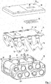
- FIG. 1 shows an exploded view of a core pack (bottom view), which is designated in its entirety by 12, and a circuit board 14 with printed circuit boards 16 (middle illustration) and an electronics housing 18 (upper illustration).
- the core pack 12 in this case comprises eight battery cells 20, two cells 20 'and 20 "being connected in parallel to form a battery cell block
- the battery cells 20 are lithium-ion cells which, unlike nickel-cadmium cells, enable a parallel connection
- Battery cell blocks consist of the battery cells 20 'and 20 "and are each connected in series one behind the other.
- the battery cells 20 are received in a cell carrier 22 and separated from each other by such that no contact of the battery cells 20 takes place with each other, as this could lead to short circuits.
- the poles of the individual battery cells 20 are hereby recessed by the cell carrier 22, so that an electrical contact can be made.
- a latching device 24 is provided on the cell carrier 22, which consists of four pins, which are provided with latching noses 26.
- the locking lugs 26 are slotted so that springs of the locking lug halves toward each other takes place so that the pins 24 including the locking lugs 26 can be guided through an opening and then takes place after rebound locking behind a projection.
- the electronics unit On the core pack 12 later in the assembly, the electronics unit is placed, which is shown in the middle illustration.
- rivets 30 are connected to the circuit board 14, the conductor plates 16 which are connected via contact areas 32 with the poles of the battery cells 20 via a material-locking connection.
- the conductor plates 16 via the conductor plates 16, both the parallel and the series connection of the individual battery cells with each other.
- the conductor plates 16 provide a connection to the electronics via the rivets 30, by means of which the conductor plates 16 are fastened to the printed circuit board 14.
- a connection of the cells 20 with the electronics via conductor plates has the advantage that vibrations can be compensated because the conductor plates 16 act as spring elements and also a mechanical connection between the circuit board and battery cells next to the electrical, which the circuit board after welding with the Battery cells 20 determines this.
- circuit board 14 recesses 34 which come to rest in the region of the tiller 24 and enclose them.
- the printed circuit board 14 is now connected to the core pack with an electronics housing 18 before assembly, which is shown in the upper illustration.
- a sponge rubber element 36 is placed on the printed circuit board 14, and printed circuit board and sponge rubber element 36 are then inserted into the electronics housing 18.
- the electronics housing 18 is then filled with a resin, so that a firm connection between the circuit board 14 and the electronics housing 18 is given.
- FIG. 2 A corresponding connection is then in FIG. 2 can be seen, in which already a casting of electronic components, such as the circuit board 14, etc., with the electronics housing 18 is done. about the foam rubber element 36 is prevented from reaching the region of the leadthrough 38 casting resin compound. About the implementation 36 is later made a Aufpen the software on the circuit board.
- both the printed circuit board 14 and the electronics housing 18 have a recess 40 and 42 in a corner region, via the cable 48 (s. FIG. 2 ) can be guided from the circuit board bottom 14 to the top of the electronics housing 18.
- the recess 42 of the electronics housing 18 has for this purpose a bracket 44, which is responsible for guiding the cable 48.
- the cables 48 are then connected to a connection dome 50 in the region of the bushing 38 and led to contacts 52, which later serve for making electrical contact with an electric hand tool device ( FIG. 2 ).
- FIG. 2 also shows an already mounted battery pack, but without battery housing.
- the electronics unit comprising the electronics housing 18 as well as the printed circuit board 14 which is no longer to be recognized have already been connected to the battery cells 20 via welded connections.
- a further damping element 46 is now arranged in the form of a foam strip between the housing and electronics housing before mounting the battery housing.
- a mechanical latching device for the battery pack with an electric hand tool device is provided with the housing.
- FIG. 3 shows a detail, in which case the locking of the core pack 12 on the cell carrier 22 and the slotted pin 24 with the electronics housing 18 can be seen.
- the tiller 24 are in terms of their length designed so that they do not protrude after locking or only slightly beyond the surface of the electronics housing 18.
Abstract
Die Erfindung betrifft ein Elektrohandwerkzeuggerät mit einem Akkupack, der mit dem Elektrohandwerkzeuggerät verbindbar ist, um das Elektrohandwerkzeuggerät mit elektrischer Energie zu versorgen, aufweisend mindestens zwei, insbesondere mindestens vier, in Reihe geschaltete Akkuzellen (20) und/oder Akkuzellenblöcke, eine Elektronikeinheit mit einer Leiterplatte (14), die unmittelbar mit den Akkuzellen verbunden ist, Leiterbleche (16), die zur elektrische Verbindung der in Reihe geschalteten Akkuzellen (20) und/oder Akkuzellenblöcke vorgesehen sind, und einen Zellenträger (22), durch den die Akkuzellen gelagert und derart durch diesen getrennt sind, dass keine Berührung der Akkuzellen untereinander erfolgt, wobei die Elektronikeinheit (18) mit der Leiterplatte (14) auf dem Zellenträger angeordnet ist.The invention relates to an electric hand tool device with a battery pack, which is connectable to the electric hand tool device to provide the electric hand tool with electrical energy, comprising at least two, in particular connected in series battery cells (20) and / or battery cell blocks, an electronic unit with a circuit board (14), which is connected directly to the battery cells, conductor plates (16) which are provided for electrically connecting the series-connected battery cells (20) and / or Akkuzellenblöcke, and a cell carrier (22) through which the battery cells stored and so are separated by this, that no contact of the battery cells takes place with each other, wherein the electronic unit (18) with the circuit board (14) is arranged on the cell carrier.
Description
Die Erfindung betrifft ein Elektrohandwerkzeuggerät mit einem Akkupack, der mit dem Elektrohandwerkzeuggerät verbindbar ist, um das Elektrohandwerkzeuggerät mit elektrischer Energie zu versorgen, aufweisend mindestens zwei, insbesondere mindestens vier, in Reihe geschaltete Akkuzellen und/oder Akkuzellenblöcke, eine Elektronikeinheit mit einer Leiterplatte, die mit den Akkuzellen unmittelbar verbunden ist, Leiterbleche, die zur elektrische Verbindung der in Reihe geschalteten Akkuzellen und/oder Akkuzellenblöcke vorgesehen sind, und einen Zellenträger.The invention relates to an electric hand tool device with a battery pack, which is connectable to the electric hand tool to provide the electric hand tool with electrical energy, comprising at least two, in particular at least four battery cells connected in series and / or Akkuzellenblöcke, an electronic unit with a circuit board with the battery cells is directly connected, conductor plates, which are provided for the electrical connection of the series-connected battery cells and / or Akkuzellenblöcke, and a cell carrier.
So ist es zum Betrieb von Elektrohandwerkzeugen vielfach vorgesehen, Akkupacks einzusetzen, da Akkugeräte eine höhere Flexibilität beim Arbeiten und insbesondere eine Unabhängigkeit von einer vorhandenen Stromquelle ermöglichten und somit auch Außenarbeiten unbeschränkt von der Frage einer Stromquelle durchgeführt werden können. Dabei weisen Akkugeräte einen wiederaufladbaren Akkumulator in einem Akkugehäuse auf, das mit dem Gerätegehäuse eines Elektrohandwerkzeuggeräts koppelbar ist, wobei beim Koppeln der beiden Gehäuse der Motor elektrisch an den Akkupack angekoppelt und darüber mit Strom versorgt wird. Zum Koppeln der beiden Gehäuse ist gewöhnlich das Akkugehäuse mit einer überstehenden Verrastvorrichtung versehen, die in eine komplementäre Einsteckbuchse des Gerätegehäuses eingeschoben und in dieser verrastet wird. Die elektrische Kontaktierung erfolgt zumeist im Bereich der Verrastvorrichtung.Thus, it is often intended to operate electric hand tools to use battery packs, as cordless tools allow greater flexibility in working and in particular independence from an existing power source and thus outdoor work can be carried out unrestricted by the question of a power source. In this case, cordless tools have a rechargeable accumulator in a rechargeable battery housing, which can be coupled to the device housing of an electric hand tool device, wherein when coupling the two housings, the motor is electrically coupled to the battery pack and supplied with power. To couple the two housings usually the battery housing is provided with a protruding latching device, which is inserted into a complementary plug-in socket of the device housing and locked in this. The electrical contact is usually in the field of Verrastvorrichtung.
In aller Regel ist es vorgesehen, die Akkuzellen untereinander bzw. Akkuzellenblöcke untereinander in Reihe zu schalten. Für die Reihenschaltung werden zum Teil sogenannte Leiterbleche verwendet, die die jeweiligen komplementären Pole einer Akkuzelle miteinander verbinden.As a rule, it is provided to connect the battery cells with each other or battery cell blocks with each other in series. For series connection Partially so-called conductor plates are used, which connect the respective complementary poles of a battery cell with each other.
Eine analoge Ausgestaltung für eine Batterie ist beispielsweise aus der
Darüber hinaus ist es bekannt, bei Lithiumionenakkus, bei denen der Ladezustand und der Aufladevorgang über die Elektronik des Akkupacks überwacht werden, vorzusehen, dass die einzelnen Akkuzellen zur Überwachung ihrer Zellen mit der Elektronik verbunden sind. Hierzu werden im Stand der Technik Litzen vorgesehen, die die Akkuzellen mit der Elektronikeinheit und hier insbesondere der Leiterplatte verbinden. Nachteilig ist dabei der verhältnismäßig hohe Montageaufwand.Moreover, it is known in lithium ion batteries, in which the state of charge and the charging process are monitored via the electronics of the battery pack to provide that the individual battery cells are connected to monitor their cells with the electronics. For this purpose, strands are provided in the prior art, which connect the battery cells with the electronic unit and in particular the circuit board. The disadvantage here is the relatively high installation costs.
Daneben ist aus den Dokumenten
Schließlich offenbart die
Es ist daher Aufgabe der Erfindung, ein Elektrohandwerkzeuggerät mit einem Akkupack bereitzustellen, bei dem eine Reihenschaltung der Akkuzellen untereinander sowie die Anbindung an die Leiterplatte vereinfacht ist. Eine weitere Aufgabe besteht darin, ein Elektrohandwerkzeuggerät mit einem besonders robusten Akkupack bereitzustellen.It is therefore an object of the invention to provide an electric hand tool device with a battery pack, in which a series connection of the battery cells with each other and the connection to the circuit board is simplified. Another object is to provide an electric hand tool device with a particularly robust battery pack.
Als Lösung schlägt die vorliegende Erfindung ein Elektrohandwerkzeuggerät mit den Merkmalen des Anspruchs 1 vor.As a solution, the present invention proposes an electric hand tool device with the features of claim 1.
Durch die Lagerung der Akkuzellen mittels eines Zellenträgers in der Weise, dass keine Berührung der Akkuzellen untereinander erfolgt, wird verhindert, dass Kurzschlüsse über die Berührung der einzelnen Akkuzellen miteinander entsteht. Der Zellenträger kann dabei insbesondere aus einem Spritzgussteil bestehen, das entsprechende Aufnahmen für die Akkuzellen aufweist.By storing the battery cells by means of a cell carrier in such a way that no contact of the battery cells with each other, prevents short circuits on the contact of the individual battery cells is formed with each other. The cell carrier may consist in particular of an injection molded part, which has corresponding receptacles for the battery cells.
Weiterhin ist die Elektronikeinheit mit der Leiterplatte auf dem Zellenträger angeordnet und ermöglicht hierdurch einen kompakten und robusten Aufbau.Furthermore, the electronic unit is arranged with the circuit board on the cell carrier, thereby enabling a compact and robust design.
Zudem ist erfindungsgemäß vorgesehen, dass der Akkupack solche Leiterbleche vorsieht, die unmittelbar mit der Leiterplatte verbunden sind. Auf diese Weise kann auf eine zusätzliche Kontaktierung über Litzen der einzelnen Akkuzellen mit der Elektronik verzichtet werden.In addition, the invention provides that the battery pack provides such conductor plates, which are directly connected to the circuit board. In this way, it is possible to dispense with additional contacting via strands of the individual battery cells with the electronics.
Dabei ist es besonders vorteilhaft, wenn gleichzeitig über die Leiterbleche eine elektrische als auch mechanische Verbindung zwischen den einzelnen Akkuzellen und der Leiterplatte erfolgt. Auf diese Weise kann gleichzeitig eine Halterung der Leiterplatte durch die Leiterbleche gegenüber einer Akkuzelle oder einem Akkuzellenblock erreicht werden. Unter Akkuzellenblöcke sind hierbei zwei oder mehr Akkuzellen zu verstehen, die parallel geschaltet sind und mit weiteren Akkuzellen oder Akkuzellenblöcken seriell gekoppelt sind.It is particularly advantageous if an electrical and mechanical connection between the individual battery cells and the circuit board takes place simultaneously via the conductor plates. In this way, at the same time a holder of the circuit board through the conductor plates opposite a battery cell or a battery cell block can be achieved. Battery cell blocks here are to be understood as two or more battery cells, which are connected in parallel and are serially coupled with further battery cells or battery cell blocks.
Dabei ist es besonders vorteilhaft, wenn die Leiterbleche mit der Leiterplatte über Nietverbindungen festgelegt sind. Zum einen wird eine besonders einfache mechanische und auch elektrische Kontaktierung über Nietverbindungen erreicht, zum anderen bietet eine Nietverbindung auch eine große Sicherheit. Schließlich kann durch eine entsprechende Nietverbindung auch ein Toleranzausgleich sowie ein Wärmedehnungsausgleich erzielt werden.It is particularly advantageous if the conductor plates are fixed to the circuit board via rivet connections. On the one hand, a particularly simple mechanical and also electrical contacting is achieved via riveted joints, on the other hand, a riveted joint also offers great security. Finally, a tolerance compensation and a thermal expansion compensation can be achieved by a corresponding rivet connection.
Dabei kann vorgesehen sein, dass die Leiterbleche geometrisch so gestaltet sind, dass sie in Form von seitlichen Anschlussfahnen von der Leiterplatte abstehen. Sie können dann so abgewinkelt werden, dass sie von der Leiterplatte in Richtung der Akkuzellen weisen.It can be provided that the conductor plates are geometrically designed so that they protrude in the form of lateral terminal lugs of the circuit board. They can then be angled so that they point from the PCB in the direction of the battery cells.
Generell besitzt die mechanisch wie auch die elektrische Kopplung über Leiterbleche an die Leiterplatte den Vorteil, dass die Leiterplatte gegenüber den Akkuzellen bzw. Akkuzellenblöcken federnd gelagert ist, da die Leiterbleche zugleich als Federelemente wirken. Auf diese Weise kann eine zusätzliche Vibrationsfestigkeit erreicht werden, da insbesondere Vibrationen, wie sie bei Elektrohandwerkzeugen, insbesondere bei Schlagbohreinrichtungen oder Bohrhämmern im Betrieb entstehen, ausgeglichen werden können.In general, the mechanical as well as the electrical coupling via conductor plates to the circuit board has the advantage that the circuit board is resiliently mounted relative to the battery cells or battery cell blocks, since the conductor plates also act as spring elements. In this way, an additional vibration resistance can be achieved, since in particular vibrations, such as those that arise in electric hand tools, in particular impact drills or hammer drills in operation, can be compensated.
Die Kombination dieser verschiedenen Gesichtspunkte in einem Bauteil stellt dabei den besonderen Vorteil der Erfindung dar.The combination of these different aspects in one component represents the particular advantage of the invention.
Die Akkuzellen können dabei insbesondere Lithiumionenzellen sein. Insbesondere bei Lithiumzellen ist es möglich, mehrere Akkuzellen zu sogenannten Akkuzellenblöcken zusammenzufassen, in denen mehrere Akkuzellen parallel geschaltet sind. Hierbei wird jeweils ein Akkuzellenblock mit der Elektronik verbunden. Mittels der Elektronik kann u. a. der Ladezustand über die Spannung der einzelnen Zellen überwacht werden. Des Weiteren kann so eine Laderegelung erfolgen. Dabei liegt hinter parallel geschalteten Zellen stets die gleiche Spannung an, so dass die Spannung bei Akkuzellenblöcken je Block bestimmt werden muss.The battery cells can be in particular lithium-ion cells. In particular, in the case of lithium cells, it is possible to combine a plurality of battery cells to form so-called battery cell blocks, in which several battery cells are connected in parallel. In each case a battery cell block is connected to the electronics. By means of electronics u. a. the state of charge can be monitored via the voltage of the individual cells. Furthermore, such a charge control can take place. In this case, the same voltage is always present behind cells connected in parallel, so that the voltage for battery cell blocks per block must be determined.
Durch die Kopplung der Akkuzellen bzw. Akkuzellenblöcke an die Leiterplatte kann festgestellt werden, ob alle Akkuzellen vorschriftsmäßig geladen werden bzw. ob gegebenenfalls ein Ladestrom erreicht wird, den die Akkuzellen nicht zu verkraften vermögen. Darüber hinaus kann eine Regelung vorgesehen sein, mittels derer der Ladestrom so geregelt wird, dass eine Überlastung einzelner Akkuzellen verhindert wird und auf der anderen Seite sämtliche Akkuzellen vollständig aufgeladen werden können. Auf diese Weise wird über lange Zeit eine gute Gebrauchsfähigkeit des entsprechenden Akkupacks und damit des mit diesem verwendeten Elektrohandwerkzeuggeräts erreicht.By coupling the battery cells or battery cell blocks to the circuit board can be determined whether all battery cells are charged properly or if, if necessary, a charging current is achieved, which can not cope with the battery cells. In addition, a scheme may be provided by means of which the charging current is controlled so that overloading of individual battery cells is prevented and on the other hand, all battery cells can be fully charged. In this way, a good usability of the corresponding battery pack and thus of the electric hand tool device used with this is achieved over a long time.
Die Pole der einzelnen Akkuzellen können dabei materialschlüssig, insbesondere über Schweiß- oder Lötverbindungen, mit den Leiterblechen verbunden sein.The poles of the individual battery cells can thereby be materially connected, in particular via welding or solder joints, with the conductor plates.
Darüber hinaus kann auch vorgesehen sein, dass am Zellenträger Befestigungselemente vorgesehen sind, mit denen der Zellenträger mit den darin aufgenommenen Akkuzellen, die gemeinsam als Corepack bezeichnet werden, mit der Elektronikeinheit verbunden wird. Eine entsprechende Verbindung kann beispielsweise über eine Rastverbindung erfolgen, indem entsprechende Rasteinrichtungen am Corepack vorgesehen sind, die Rastvorsprünge unter mechanischer Verformung an der Elektronikeinheit hintergreifen und so für eine formschlüssige Verbindung sorgen.In addition, it can also be provided that fastening elements are provided on the cell carrier, with which the cell carrier is connected to the battery cells received therein, which are collectively referred to as core pack, with the electronic unit. A corresponding Connection can be made, for example via a latching connection by appropriate locking devices are provided on the core pack, engage behind the locking projections under mechanical deformation of the electronic unit and so ensure a positive connection.
Die Elektronikeinheit kann über die Leiterplatte hinaus noch ein Elektronikgehäuse umfassen, in das die Leiterplatte mit den hieran montierten Leiterblechen aufgenommen wird. Die Leiterplatte trägt schließlich eine Reihe weiterer Elektronikelemente und es kann eine Software zur Steuerung, Regelung oder auch zur Erkennung des Akkupacks auf die Leiterplatte aufgespielt werden. Darüber hinaus können weitere Bauteile, wie insbesondere Schalter, aber auch Ladezustandsanzeigen, mit der Leiterplatte verbunden sein. Die Leiterplatte wird dann insbesondere in das Elektronikgehäuse eingefügt, und das Elektronikgehäuse wird dann mittels eines Harzes ausgegossen, so dass die Leiterplatte mit dem Elektronikgehäuse fest verbunden ist.The electronics unit can also comprise an electronics housing beyond the printed circuit board into which the printed circuit board with the printed circuit boards mounted thereon is received. The circuit board finally carries a number of other electronic elements and it can be a software for control, regulation or even the detection of the battery pack are printed on the circuit board. In addition, other components, such as switches in particular, but also state of charge indicators, be connected to the circuit board. The circuit board is then inserted in particular into the electronics housing, and the electronics housing is then poured out by means of a resin, so that the circuit board is firmly connected to the electronics housing.
Schließlich umfasst die Erfindung ein Akkupack insbesondere für ein Elektrohandwerkzeuggerät mit den Merkmalen des Anspruchs 12.Finally, the invention comprises a battery pack, in particular for an electric hand tool with the features of
Die Erfindung soll im Folgenden anhand einer Zeichnung näher erläutert werden. Dabei zeigen:
- Figur 1
- eine Explosionsdarstellung der Elektronikeinheit sowie eines Corepacks eines Akkupacks;
- Figur 2
- einen Akkupack ohne Akkugehäuse; und
- Figur 3
- einen Ausschnitt aus
Figur 2 hinsichtlich der Verrastung.
- FIG. 1
- an exploded view of the electronics unit and a core pack of a battery pack;
- FIG. 2
- a battery pack without battery housing; and
- FIG. 3
- a section from
FIG. 2 in terms of latching.
Das Corepack 12 umfasst hierbei acht Akkuzellen 20, wobei jeweils zwei Zellen 20' und 20" zu einem Akkuzellenblock parallel geschaltet sind. Bei den Akkuzellen 20 handelt es sich um Lithiumionenzellen, die, anders als Nickel-Cadmium-Zellen, eine Parallelschaltung ermöglichen. Die Akkuzellenblöcke bestehen aus den Akkuzellen 20' und 20" und sind jeweils in Reihe hintereinander geschaltet. Die Akkuzellen 20 sind in einen Zellenträger 22 aufgenommen und durch diesen voneinander derart getrennt, dass keine Berührung der Akkuzellen 20 untereinander erfolgt, da dies zu Kurzschlüssen führen könnte. Die Pole der einzelnen Akkuzellen 20 sind hierbei durch den Zellenträger 22 ausgespart, so dass eine elektrische Kontaktierung vorgenommen werden kann.The
Darüber hinaus ist am Zellenträger 22 eine Verrastvorrichtung 24 vorgesehen, die aus vier Pinnen besteht, die mit Rastnasen 26 versehen. Die Rastnasen 26 sind so geschlitzt, dass ein Federn der Rastnasenhälften aufeinanderzu so erfolgt, dass die Pinnen 24 einschließlich der Rastnasen 26 durch eine Öffnungen geführt werden können und dann nach Ausfedern eine Verrastung hinter einem Vorsprung erfolgt.In addition, a latching
Auf den Corepack 12 wird später bei der Montage die Elektronikeinheit aufgesetzt, die in der mittleren Darstellung gezeigt ist. Diese beinhaltet eine Leiterplatte 14, auf deren Oberseite 27 verschiedene Lötstellen vorgesehen sind und die darüber hinaus auch eine Schaltung trägt, die es ermöglicht, eine Software aufzuspielen. Weitere Baugruppen der Elektronik sind auf der Unterseite 28 der Leiterplatte 14 angeordnet, wie beispielsweise Lichtquellen für eine Ladezustandsanzeige sowie Schalter etc..On the
Über Nieten 30 mit der Leiterplatte 14 verbunden sind die Leiterbleche 16, die über Kontaktbereiche 32 mit den Polen der Akkuzellen 20 über eine materialschlüssige Verbindung verbunden werden. Dabei erfolgt über die Leiterbleche 16 sowohl die Parallel- als auch die Reihenschaltung der einzelnen Akkuzellen untereinander. Darüber hinaus sorgen die Leiterbleche 16 für eine Verbindung mit der Elektronik über die Nieten 30, mittels derer die Leiterbleche 16 an der Leiterplatte 14 befestigt sind.About rivets 30 are connected to the
Eine Verbindung der Zellen 20 mit der Elektronik über Leiterbleche besitzt dabei den Vorteil, dass Schwingungen ausgeglichen werden können, da die Leiterbleche 16 als Federelemente wirken und auch eine mechanische Verbindung zwischen Leiterplatte und Akkuzellen neben der elektrischen erfolgt, die die Leiterplatte nach einer Verschweißung mit den Akkuzellen 20 an diesen festlegt.A connection of the
Darüber hinaus weist die Leiterplatte 14 Ausnehmungen 34 auf, die im Bereich der Pinne 24 zu liegen kommen und diese umschließen.In addition, the
Die Leiterplatte 14 wird nun vor Montage mit dem Corepack mit einem Elektronikgehäuse 18 verbunden, das in der oberen Darstellung gezeigt ist. Hierzu wird auf die Leiterplatte 14 ein Moosgummielement 36 aufgelegt, und Leiterplatte und Moosgummielement 36 werden dann in das Elektronikgehäuse 18 eingefügt. Das Elektronikgehäuse 18 wird anschließend mit einem Harz ausgegossen, so dass eine feste Verbindung zwischen der Leiterplatte 14 und dem Elektronikgehäuse 18 gegeben ist.The printed
Eine entsprechende Verbindung ist dann in
Darüber hinaus weisen sowohl Leiterplatte 14 als auch das Elektronikgehäuse 18 eine Ausnehmung 40 bzw. 42 in einem Eckbereich auf, über den Kabel 48 (s.
Mit dem Gehäuse wird schließlich noch eine mechanische Verrastvorrichtung für den Akkupack mit einem Elektrohandwerkzeuggerät bereitgestellt.Finally, a mechanical latching device for the battery pack with an electric hand tool device is provided with the housing.
Auf die vorstehend beschriebene Weise kann besonders einfach eine elektrische und eine mechanische Kopplung von Akkuzellen 20 mit einer Leiterplatte realisiert werden. Über die elektrische Kopplung ist es möglich, den Ladezustand über die Spannung der einzelnen Akkuzellen 20 bzw. Akkuzellenblöcke zu ermitteln, um hierüber den Ladevorgang zu steuern. Darüber hinaus bietet eine entsprechende Anordnung den Vorteil einer sicheren elektrischen Verbindung der Akkuzellen 20 untereinander und zur Elektronik sowie einer Vibrationsfestigkeit.In the manner described above, it is particularly easy to realize electrical and mechanical coupling of
Claims (12)
wobei die Leiterbleche (16) von dem Zellenträger gestützt sind.Electric hand tool according to claim 1,
wherein the conductor plates (16) are supported by the cell carrier.
wobei der Zellenträger (22) Aussparungen im Bereich der Pole der aufgenommenen Akkuzellen (20) zur Herstellung der elektrischen Verbindung der Akkuzellen (20) mit den Leiterblechen (16) aufweist.Electric hand tool according to claim 1 or 2,
wherein the cell carrier (22) recesses in the region of the poles of the received battery cells (20) for establishing the electrical connection of the battery cells (20) with the conductor plates (16).
wobei alle Akkuzellen und/oder alle Akkuzellenblöcke des Akkupacks mittels Leiterblechen elektrisch in Reihe geschaltet sind.Electric hand tool according to one of the preceding claims,
wherein all battery cells and / or all battery cell blocks of the battery pack are electrically connected in series by means of conductor plates.
wobei die Leiterbleche (16) insbesondere über Nietverbindungen (30) an der Leiterplatte (14) festgelegt sind.Electric hand tool according to one of the preceding claims,
wherein the conductor plates (16) are fixed in particular via rivet connections (30) on the printed circuit board (14).
wobei die Akkuzellen (20) Lithiumionenzellen sind.Electric hand tool according to one of the preceding claims,
wherein the battery cells (20) are lithium ion cells.
wobei die Leiterbleche (16) mit Polen der Akkuzellen (20) über eine Schweiß- oder Lötverbindung verbunden sind.Electric hand tool according to one of the preceding claims,
wherein the conductor plates (16) are connected to poles of the battery cells (20) via a welded or soldered connection.
wobei die Leiterbleche (16) über ein Verbindungselement zugleich elektrisch und mechanisch mit der Leiterplatte (14) verbunden sind.Electric hand tool according to one of the preceding claims,
wherein the conductor plates (16) via a connecting element at the same time electrically and mechanically connected to the circuit board (14).
wobei die Leiterplatte (14) mit den montierten Leiterblechen (16) in ein Elektronikgehäuse (18) aufgenommen und insbesondere hierin eingegossen ist.Electric hand tool according to one of the preceding claims,
wherein the printed circuit board (14) with the mounted conductor plates (16) accommodated in an electronics housing (18) and in particular cast therein.
wobei das Elektronikgehäuse (18) mittels einer Rastverbindung auf dem Zellenträger (22) festlegbar ist.Electric hand tool device according to claim 9,
wherein the electronics housing (18) by means of a latching connection on the cell carrier (22) can be fixed.
mindestens zwei, insbesondere mindestens vier, in Reihe geschaltete Akkuzellen (20) und/oder Akkuzellenblöcke, eine Elektronikeinheit mit einer Leiterplatte (14), die unmittelbar mit den Akkuzellen verbunden ist,
Leiterbleche (16), die zur elektrische Verbindung der in Reihe geschalteten Akkuzellen (20) und/oder Akkuzellenblöcke vorgesehen sind, und
einen Zellenträger (22), durch den die Akkuzellen gelagert und derart durch diesen getrennt sind, dass keine Berührung der Akkuzellen untereinander erfolgt,
wobei die Elektronikeinheit (18) mit der Leiterplatte (14) auf dem Zellenträger angeordnet ist.Battery pack in particular for an electric hand tool device having
at least two, in particular at least four, battery cells (20) connected in series and / or battery cell blocks, an electronic unit with a printed circuit board (14) which is connected directly to the battery cells,
Conductor plates (16), which are provided for the electrical connection of the series-connected battery cells (20) and / or Akkuzellenblöcke, and
a cell carrier (22) through which the battery cells are stored and separated by the battery cells, so that no contact is made between the battery cells,
wherein the electronic unit (18) with the printed circuit board (14) is arranged on the cell carrier.
Priority Applications (1)
| Application Number | Priority Date | Filing Date | Title |
|---|---|---|---|
| EP16195951.5A EP3154106B1 (en) | 2005-09-20 | 2005-09-20 | Power tool |
Applications Claiming Priority (3)
| Application Number | Priority Date | Filing Date | Title |
|---|---|---|---|
| EP05793680.9A EP1927147B1 (en) | 2005-09-20 | 2005-09-20 | Rechargeable battery pack and electrical hand tool device |
| PCT/EP2005/010108 WO2007033689A1 (en) | 2005-09-20 | 2005-09-20 | Rechargeable battery pack and electrical hand tool device |
| EP16195951.5A EP3154106B1 (en) | 2005-09-20 | 2005-09-20 | Power tool |
Related Parent Applications (2)
| Application Number | Title | Priority Date | Filing Date |
|---|---|---|---|
| EP05793680.9A Division EP1927147B1 (en) | 2005-09-20 | 2005-09-20 | Rechargeable battery pack and electrical hand tool device |
| EP05793680.9A Division-Into EP1927147B1 (en) | 2005-09-20 | 2005-09-20 | Rechargeable battery pack and electrical hand tool device |
Publications (2)
| Publication Number | Publication Date |
|---|---|
| EP3154106A1 true EP3154106A1 (en) | 2017-04-12 |
| EP3154106B1 EP3154106B1 (en) | 2024-01-10 |
Family
ID=35967053
Family Applications (2)
| Application Number | Title | Priority Date | Filing Date |
|---|---|---|---|
| EP05793680.9A Active EP1927147B1 (en) | 2005-09-20 | 2005-09-20 | Rechargeable battery pack and electrical hand tool device |
| EP16195951.5A Active EP3154106B1 (en) | 2005-09-20 | 2005-09-20 | Power tool |
Family Applications Before (1)
| Application Number | Title | Priority Date | Filing Date |
|---|---|---|---|
| EP05793680.9A Active EP1927147B1 (en) | 2005-09-20 | 2005-09-20 | Rechargeable battery pack and electrical hand tool device |
Country Status (4)
| Country | Link |
|---|---|
| US (2) | US8663834B2 (en) |
| EP (2) | EP1927147B1 (en) |
| CN (1) | CN101268569A (en) |
| WO (1) | WO2007033689A1 (en) |
Cited By (2)
| Publication number | Priority date | Publication date | Assignee | Title |
|---|---|---|---|---|
| EP3531473A1 (en) * | 2018-02-26 | 2019-08-28 | Metabowerke GmbH | Battery pack and hand-held power tool and method of manufacturing the same |
| DE102019117047A1 (en) * | 2019-06-25 | 2020-12-31 | Jungheinrich Aktiengesellschaft | Vibration-dampening storage of battery stacks and electrical parts |
Families Citing this family (50)
| Publication number | Priority date | Publication date | Assignee | Title |
|---|---|---|---|---|
| EP1927147B1 (en) | 2005-09-20 | 2016-12-14 | Metabowerke GmbH | Rechargeable battery pack and electrical hand tool device |
| EP2919295B1 (en) * | 2005-10-31 | 2018-08-29 | Black & Decker, Inc. | Method of arranging the components of a battery pack |
| EP2006054A1 (en) * | 2007-06-22 | 2008-12-24 | Metabowerke GmbH | Battery cells holding device for a battery pack |
| US20090061302A1 (en) * | 2007-09-04 | 2009-03-05 | Scott John S | Battery pack including an electric harness and method of manufacturing the same |
| DE102008040341A1 (en) | 2008-07-11 | 2010-01-14 | Robert Bosch Gmbh | Accumulator with several accumulator cells |
| US20100055560A1 (en) | 2008-08-29 | 2010-03-04 | Youngcheol Jang | Secondary battery |
| JP5284053B2 (en) * | 2008-11-17 | 2013-09-11 | 株式会社東芝 | Secondary battery pack |
| DE102009012176A1 (en) | 2009-02-27 | 2010-09-02 | Andreas Stihl Ag & Co. Kg | Battery pack with monitoring electronics integrated in the housing cover |
| JP5405189B2 (en) * | 2009-05-11 | 2014-02-05 | 三洋電機株式会社 | Pack battery |
| KR101065926B1 (en) * | 2009-07-09 | 2011-09-19 | 삼성에스디아이 주식회사 | Secondary battery |
| DE102009041738B4 (en) * | 2009-07-25 | 2015-11-05 | Zehdenick Innovative Metall- Und Kunststofftechnik Gmbh | Arrangement for connecting electrical conductors to pole terminals of interconnected cells |
| EP2325917B1 (en) * | 2009-10-21 | 2014-03-12 | Samsung SDI Co., Ltd. | Battery assembly |
| EP2532040A4 (en) * | 2010-02-05 | 2014-10-01 | Alelion Batteries Ab | Battery assembly |
| JP2011222391A (en) * | 2010-04-13 | 2011-11-04 | Makita Corp | Battery pack |
| KR101136310B1 (en) * | 2010-06-07 | 2012-04-19 | 에스비리모티브 주식회사 | Battery pack |
| JP5462096B2 (en) | 2010-07-15 | 2014-04-02 | 株式会社マキタ | Battery for power tools |
| JP5574422B2 (en) * | 2010-09-16 | 2014-08-20 | Fdkトワイセル株式会社 | Circuit board support device and battery unit including the circuit board support device |
| JP5297431B2 (en) * | 2010-09-27 | 2013-09-25 | パナソニック株式会社 | Battery pack and electric tool equipped with the same |
| US20130224532A1 (en) * | 2010-11-05 | 2013-08-29 | Alelion Batteries Ab | Battery assembly |
| KR101223733B1 (en) * | 2011-01-24 | 2013-01-17 | 삼성에스디아이 주식회사 | Electrode connector and battery module using the same |
| US9178192B2 (en) * | 2011-05-13 | 2015-11-03 | Lg Chem, Ltd. | Battery module and method for manufacturing the battery module |
| FR2976761B1 (en) * | 2011-06-17 | 2014-05-02 | Commissariat Energie Atomique | PRINTED CIRCUIT FOR INTERCONNECTING AND MEASURING BATTERY BATTERY ACCUMULATORS |
| US20130164567A1 (en) * | 2011-06-24 | 2013-06-27 | Seektech, Inc. | Modular battery pack apparatus, systems, and methods |
| TWI371883B (en) * | 2011-07-08 | 2012-09-01 | Simplo Technology Company Ltd | Battery module and related forming method,battery cell assembly,bus layout structure of a battery module and related layout method,cpnnection structure and connection method between battery cells and conductiog buses of a battery module, and connection s |
| US9496544B2 (en) | 2011-07-28 | 2016-11-15 | Lg Chem. Ltd. | Battery modules having interconnect members with vibration dampening portions |
| US9293747B2 (en) | 2011-08-01 | 2016-03-22 | Ingersoll-Rand Company | Multi cell carriers |
| EP2744015A4 (en) * | 2011-08-10 | 2014-12-24 | Panasonic Corp | Battery block and battery module comprising same |
| US8974938B2 (en) | 2011-08-30 | 2015-03-10 | Lg Chem, Ltd. | Battery system and method for coupling a battery cell assembly to an electrically non-conductive base member |
| US8871376B2 (en) | 2011-08-31 | 2014-10-28 | Lg Chem, Ltd. | Interconnection assemblies and methods for forming the interconnection assemblies in a battery module |
| US8846240B2 (en) | 2012-02-16 | 2014-09-30 | Lg Chem, Ltd. | Battery cell interconnect and voltage sensing assembly and method of manufacturing the assembly |
| CN105830248B (en) * | 2013-12-17 | 2019-11-01 | 胡斯华纳有限公司 | Battery pack with battery fixed equipment |
| JP6492668B2 (en) * | 2014-01-23 | 2019-04-03 | 株式会社村田製作所 | Power storage device, power storage system, electronic device, electric vehicle, and power system |
| US9437859B2 (en) | 2014-04-07 | 2016-09-06 | Lg Chem, Ltd. | Battery cell interconnect and voltage sensing assembly and a battery module |
| US9620761B2 (en) | 2014-09-09 | 2017-04-11 | Lg Chem, Ltd. | Battery cell interconnect and voltage sensing assembly and a battery module |
| CN104409670B (en) * | 2014-12-05 | 2016-10-05 | 江苏天鹏电源有限公司 | A kind of 18V battery bag of simple in construction good damping effect |
| US10020483B2 (en) | 2015-02-09 | 2018-07-10 | Lg Chem, Ltd. | Battery module and method of coupling first and second electrical terminals of first and second battery cells to a voltage sense member of an interconnect assembly |
| US9905892B2 (en) | 2015-02-09 | 2018-02-27 | Lg Chem, Ltd. | Battery module and method of coupling first and second electrical terminals of first and second battery cells to first and second voltage sense members of an interconnect assembly |
| DE102015110308B4 (en) | 2015-03-09 | 2022-01-20 | Metabowerke Gmbh | Battery pack for an electric hand tool |
| MX360033B (en) * | 2015-06-11 | 2018-10-19 | Pedro Gabay Villafana | Electronic device for detecting magnetic fields, which indicates the gas level in stationary tanks and data sent in a wireless manner. |
| US11735778B2 (en) | 2016-09-20 | 2023-08-22 | Honeywell Limited | Battery pack device with casings for multiple cells |
| DE102017107868A1 (en) | 2017-04-11 | 2018-10-11 | Metabowerke Gmbh | Battery pack and electric hand tool |
| FR3071671B1 (en) * | 2017-09-22 | 2022-02-18 | Tyva Energie | ELECTRIC BATTERY |
| DE102018104339A1 (en) | 2018-02-26 | 2019-08-29 | Metabowerke Gmbh | Battery pack and electric hand tool |
| DE102018104342B3 (en) | 2018-02-26 | 2019-07-04 | Metabowerke Gmbh | Battery pack and electric hand tool |
| DE102018109209A1 (en) | 2018-04-18 | 2019-10-24 | Metabowerke Gmbh | Battery pack and electric hand tool |
| DE102018206883A1 (en) * | 2018-05-04 | 2019-11-07 | Robert Bosch Gmbh | battery Pack |
| WO2020074790A1 (en) * | 2018-10-09 | 2020-04-16 | Tyva Energie | Electric battery |
| WO2020095325A1 (en) | 2018-11-08 | 2020-05-14 | Tvs Motor Company Limited | Interconnecting structure for energy storage cells in an energy storage device |
| US11539511B2 (en) * | 2019-08-08 | 2022-12-27 | Lenovo (Singapore) Pte. Ltd. | Use of conductive ink segments to establish secure device key |
| IL294828A (en) * | 2020-01-23 | 2022-09-01 | Bren Tronics Inc | Ballistic resistant case for rechargeable batteries |
Citations (7)
| Publication number | Priority date | Publication date | Assignee | Title |
|---|---|---|---|---|
| DE3246968A1 (en) | 1982-12-18 | 1984-07-19 | Varta Batterie Ag, 3000 Hannover | Electrical battery having a plurality of cylindrical cells which are located side by side and are arranged parallel to one another |
| DE9404070U1 (en) | 1994-03-10 | 1994-05-19 | Fan Chang We Chuan | Battery pack |
| EP1109237A1 (en) | 1999-12-13 | 2001-06-20 | Alcatel | Module configuration |
| DE10055158A1 (en) * | 1999-11-10 | 2001-07-12 | Makita Corp | Battery pack used as electric power unit, has ventilator through which air for cooling is passed from inlet port into circumference of storage batteries and is ejected out through exhaust port |
| JP2004321284A (en) | 2003-04-22 | 2004-11-18 | Matsushita Electric Ind Co Ltd | Vacuum cleaner |
| EP1548859A2 (en) * | 1999-07-15 | 2005-06-29 | BLACK & DECKER INC. | Battery pack and method for constructing same |
| JP2005209369A (en) * | 2004-01-20 | 2005-08-04 | Matsushita Electric Ind Co Ltd | Battery pack |
Family Cites Families (7)
| Publication number | Priority date | Publication date | Assignee | Title |
|---|---|---|---|---|
| DE3246938C2 (en) | 1982-12-18 | 1986-04-10 | LEMO M. Lehmacher & Sohn GmbH Maschinenfabrik, 5216 Niederkassel | Positioning and parking device for the plate cylinder and the inking roller of a flexographic printing machine |
| KR20020070653A (en) * | 2002-05-09 | 2002-09-10 | (주) 모비파워 | Battery pack |
| JP3837366B2 (en) * | 2002-06-28 | 2006-10-25 | 三洋電機株式会社 | Pack battery |
| JP4036805B2 (en) * | 2003-08-05 | 2008-01-23 | 三洋電機株式会社 | Pack battery |
| EP1927147B1 (en) | 2005-09-20 | 2016-12-14 | Metabowerke GmbH | Rechargeable battery pack and electrical hand tool device |
| CN203721827U (en) * | 2013-12-10 | 2014-07-16 | 新源动力股份有限公司 | Fuel cell stack end plate with compensation function |
| US11322771B2 (en) * | 2019-12-30 | 2022-05-03 | Hyaxiom, Inc. | Fuel cell tie rod isolator |
-
2005
- 2005-09-20 EP EP05793680.9A patent/EP1927147B1/en active Active
- 2005-09-20 US US12/067,367 patent/US8663834B2/en active Active
- 2005-09-20 EP EP16195951.5A patent/EP3154106B1/en active Active
- 2005-09-20 WO PCT/EP2005/010108 patent/WO2007033689A1/en active Application Filing
- 2005-09-20 CN CNA2005800516071A patent/CN101268569A/en active Pending
-
2014
- 2014-01-16 US US14/156,787 patent/US9385401B2/en active Active
Patent Citations (7)
| Publication number | Priority date | Publication date | Assignee | Title |
|---|---|---|---|---|
| DE3246968A1 (en) | 1982-12-18 | 1984-07-19 | Varta Batterie Ag, 3000 Hannover | Electrical battery having a plurality of cylindrical cells which are located side by side and are arranged parallel to one another |
| DE9404070U1 (en) | 1994-03-10 | 1994-05-19 | Fan Chang We Chuan | Battery pack |
| EP1548859A2 (en) * | 1999-07-15 | 2005-06-29 | BLACK & DECKER INC. | Battery pack and method for constructing same |
| DE10055158A1 (en) * | 1999-11-10 | 2001-07-12 | Makita Corp | Battery pack used as electric power unit, has ventilator through which air for cooling is passed from inlet port into circumference of storage batteries and is ejected out through exhaust port |
| EP1109237A1 (en) | 1999-12-13 | 2001-06-20 | Alcatel | Module configuration |
| JP2004321284A (en) | 2003-04-22 | 2004-11-18 | Matsushita Electric Ind Co Ltd | Vacuum cleaner |
| JP2005209369A (en) * | 2004-01-20 | 2005-08-04 | Matsushita Electric Ind Co Ltd | Battery pack |
Cited By (2)
| Publication number | Priority date | Publication date | Assignee | Title |
|---|---|---|---|---|
| EP3531473A1 (en) * | 2018-02-26 | 2019-08-28 | Metabowerke GmbH | Battery pack and hand-held power tool and method of manufacturing the same |
| DE102019117047A1 (en) * | 2019-06-25 | 2020-12-31 | Jungheinrich Aktiengesellschaft | Vibration-dampening storage of battery stacks and electrical parts |
Also Published As
| Publication number | Publication date |
|---|---|
| WO2007033689A1 (en) | 2007-03-29 |
| EP3154106B1 (en) | 2024-01-10 |
| US20080254356A1 (en) | 2008-10-16 |
| EP1927147B1 (en) | 2016-12-14 |
| US8663834B2 (en) | 2014-03-04 |
| EP1927147A1 (en) | 2008-06-04 |
| US9385401B2 (en) | 2016-07-05 |
| US20140162089A1 (en) | 2014-06-12 |
| CN101268569A (en) | 2008-09-17 |
Similar Documents
| Publication | Publication Date | Title |
|---|---|---|
| EP1927147B1 (en) | Rechargeable battery pack and electrical hand tool device | |
| EP3424095B1 (en) | Battery pack for handheld powertool | |
| DE102006061270B4 (en) | Battery pack and battery module | |
| EP2639857B1 (en) | Connection system for an energy storage device and energy storage device with the connection system | |
| DE102008045780B4 (en) | Method for producing a cabling carrier for a battery pack, method for producing the battery pack, and also cabling carrier and battery pack | |
| DE19620834C1 (en) | Cordless telephone combined base station and charging station | |
| DE102016203422A1 (en) | Battery pack for a hand tool | |
| DE102014010067B4 (en) | Motor vehicle battery that can be produced with voltage protection, plug-in module for a motor vehicle battery, motor vehicle with at least one motor vehicle battery and method for producing a motor vehicle battery | |
| WO2009007163A1 (en) | Rechargeable battery | |
| DE102012215205A1 (en) | Cell connector for use in battery cell module of battery in e.g. electromotive drivable motor car, has access devices connecting connector with terminals of cells, where covering device with which one of access devices is partly covered | |
| EP3364493B1 (en) | Battery pack with temperature sensor | |
| EP3747069A1 (en) | Energy storage module having energy storage cells connected via uninsulated conductor pieces and/or having a cooling system, energy storage block and method for cooling an energy storage module | |
| EP3657570A1 (en) | Battery module | |
| DE202005022111U1 (en) | Battery pack and electric hand tool | |
| DE102014205724A1 (en) | Energy storage device | |
| DE102013201358A1 (en) | Electrical connector for e.g. lithium-ion battery cell for battery pack of motor car, has spring contact supported on two abutments and control element arranged rotatably between spring contacts in region between abutments | |
| DE102009035469A1 (en) | Battery i.e. lithium ion battery, for use in e.g. hybrid drive vehicle, has single cells provided with set of contact units, and head-laterally cell monitoring device provided with another set of units with respect to former set of units | |
| DE102008054639A1 (en) | Energy transmission device | |
| DE202017006869U1 (en) | Battery pack, electrical appliance using the battery pack and electrical appliance system | |
| DE102013202574B4 (en) | Memory module | |
| DE102014100399B4 (en) | starter battery | |
| WO2022033733A1 (en) | Power distribution unit for a mobile machine, and mobile machine comprising the power distribution unit | |
| DE102012015910A1 (en) | Battery, in particular for a motor vehicle, and motor vehicle | |
| EP2494630A1 (en) | Electrochemical cell | |
| DE102019208769A1 (en) | accumulator |
Legal Events
| Date | Code | Title | Description |
|---|---|---|---|
| PUAI | Public reference made under article 153(3) epc to a published international application that has entered the european phase |
Free format text: ORIGINAL CODE: 0009012 |
|
| STAA | Information on the status of an ep patent application or granted ep patent |
Free format text: STATUS: THE APPLICATION HAS BEEN PUBLISHED |
|
| AC | Divisional application: reference to earlier application |
Ref document number: 1927147 Country of ref document: EP Kind code of ref document: P |
|
| AK | Designated contracting states |
Kind code of ref document: A1 Designated state(s): AT BE BG CH CY CZ DE DK EE ES FI FR GB GR HU IE IS IT LI LT LU LV MC NL PL PT RO SE SI SK TR |
|
| STAA | Information on the status of an ep patent application or granted ep patent |
Free format text: STATUS: REQUEST FOR EXAMINATION WAS MADE |
|
| 17P | Request for examination filed |
Effective date: 20171011 |
|
| RBV | Designated contracting states (corrected) |
Designated state(s): AT BE BG CH CY CZ DE DK EE ES FI FR GB GR HU IE IS IT LI LT LU LV MC NL PL PT RO SE SI SK TR |
|
| STAA | Information on the status of an ep patent application or granted ep patent |
Free format text: STATUS: EXAMINATION IS IN PROGRESS |
|
| 17Q | First examination report despatched |
Effective date: 20181005 |
|
| STAA | Information on the status of an ep patent application or granted ep patent |
Free format text: STATUS: EXAMINATION IS IN PROGRESS |
|
| STAA | Information on the status of an ep patent application or granted ep patent |
Free format text: STATUS: EXAMINATION IS IN PROGRESS |
|
| REG | Reference to a national code |
Ref country code: DE Ref legal event code: R079 Free format text: PREVIOUS MAIN CLASS: H01M0002100000 Ipc: H01M0010052000 Ref country code: DE Ref legal event code: R079 Ref document number: 502005016205 Country of ref document: DE Free format text: PREVIOUS MAIN CLASS: H01M0002100000 Ipc: H01M0010052000 |
|
| RIC1 | Information provided on ipc code assigned before grant |
Ipc: H01M 10/46 20060101ALI20230525BHEP Ipc: H01M 50/528 20210101ALI20230525BHEP Ipc: H01M 50/522 20210101ALI20230525BHEP Ipc: H01M 50/516 20210101ALI20230525BHEP Ipc: H01M 50/51 20210101ALI20230525BHEP Ipc: H01M 50/509 20210101ALI20230525BHEP Ipc: H01M 50/503 20210101ALI20230525BHEP Ipc: H01M 50/213 20210101ALI20230525BHEP Ipc: H01M 10/052 20100101AFI20230525BHEP |
|
| GRAP | Despatch of communication of intention to grant a patent |
Free format text: ORIGINAL CODE: EPIDOSNIGR1 |
|
| STAA | Information on the status of an ep patent application or granted ep patent |
Free format text: STATUS: GRANT OF PATENT IS INTENDED |
|
| INTG | Intention to grant announced |
Effective date: 20230904 |
|
| GRAS | Grant fee paid |
Free format text: ORIGINAL CODE: EPIDOSNIGR3 |
|
| GRAA | (expected) grant |
Free format text: ORIGINAL CODE: 0009210 |
|
| STAA | Information on the status of an ep patent application or granted ep patent |
Free format text: STATUS: THE PATENT HAS BEEN GRANTED |
|
| AC | Divisional application: reference to earlier application |
Ref document number: 1927147 Country of ref document: EP Kind code of ref document: P |
|
| AK | Designated contracting states |
Kind code of ref document: B1 Designated state(s): AT BE BG CH CY CZ DE DK EE ES FI FR GB GR HU IE IS IT LI LT LU LV MC NL PL PT RO SE SI SK TR |
|
| REG | Reference to a national code |
Ref country code: GB Ref legal event code: FG4D Free format text: NOT ENGLISH |
|
| REG | Reference to a national code |
Ref country code: CH Ref legal event code: EP |
|
| REG | Reference to a national code |
Ref country code: DE Ref legal event code: R096 Ref document number: 502005016205 Country of ref document: DE |
|
| REG | Reference to a national code |
Ref country code: IE Ref legal event code: FG4D Free format text: LANGUAGE OF EP DOCUMENT: GERMAN |