EP3153948A1 - Vibrating device and haptic device - Google Patents
Vibrating device and haptic device Download PDFInfo
- Publication number
- EP3153948A1 EP3153948A1 EP15805753.9A EP15805753A EP3153948A1 EP 3153948 A1 EP3153948 A1 EP 3153948A1 EP 15805753 A EP15805753 A EP 15805753A EP 3153948 A1 EP3153948 A1 EP 3153948A1
- Authority
- EP
- European Patent Office
- Prior art keywords
- diaphragm
- film
- vibrating device
- piezoelectric film
- spacer
- Prior art date
- Legal status (The legal status is an assumption and is not a legal conclusion. Google has not performed a legal analysis and makes no representation as to the accuracy of the status listed.)
- Granted
Links
Images





Classifications
-
- G—PHYSICS
- G06—COMPUTING OR CALCULATING; COUNTING
- G06F—ELECTRIC DIGITAL DATA PROCESSING
- G06F3/00—Input arrangements for transferring data to be processed into a form capable of being handled by the computer; Output arrangements for transferring data from processing unit to output unit, e.g. interface arrangements
- G06F3/01—Input arrangements or combined input and output arrangements for interaction between user and computer
- G06F3/016—Input arrangements with force or tactile feedback as computer generated output to the user
-
- B—PERFORMING OPERATIONS; TRANSPORTING
- B06—GENERATING OR TRANSMITTING MECHANICAL VIBRATIONS IN GENERAL
- B06B—METHODS OR APPARATUS FOR GENERATING OR TRANSMITTING MECHANICAL VIBRATIONS OF INFRASONIC, SONIC, OR ULTRASONIC FREQUENCY, e.g. FOR PERFORMING MECHANICAL WORK IN GENERAL
- B06B1/00—Methods or apparatus for generating mechanical vibrations of infrasonic, sonic, or ultrasonic frequency
- B06B1/02—Methods or apparatus for generating mechanical vibrations of infrasonic, sonic, or ultrasonic frequency making use of electrical energy
- B06B1/06—Methods or apparatus for generating mechanical vibrations of infrasonic, sonic, or ultrasonic frequency making use of electrical energy operating with piezoelectric effect or with electrostriction
- B06B1/0688—Methods or apparatus for generating mechanical vibrations of infrasonic, sonic, or ultrasonic frequency making use of electrical energy operating with piezoelectric effect or with electrostriction with foil-type piezoelectric elements, e.g. PVDF
-
- G—PHYSICS
- G06—COMPUTING OR CALCULATING; COUNTING
- G06F—ELECTRIC DIGITAL DATA PROCESSING
- G06F3/00—Input arrangements for transferring data to be processed into a form capable of being handled by the computer; Output arrangements for transferring data from processing unit to output unit, e.g. interface arrangements
- G06F3/01—Input arrangements or combined input and output arrangements for interaction between user and computer
- G06F3/03—Arrangements for converting the position or the displacement of a member into a coded form
- G06F3/041—Digitisers, e.g. for touch screens or touch pads, characterised by the transducing means
-
- H—ELECTRICITY
- H10—SEMICONDUCTOR DEVICES; ELECTRIC SOLID-STATE DEVICES NOT OTHERWISE PROVIDED FOR
- H10N—ELECTRIC SOLID-STATE DEVICES NOT OTHERWISE PROVIDED FOR
- H10N30/00—Piezoelectric or electrostrictive devices
- H10N30/704—Piezoelectric or electrostrictive devices based on piezoelectric or electrostrictive films or coatings
- H10N30/706—Piezoelectric or electrostrictive devices based on piezoelectric or electrostrictive films or coatings characterised by the underlying bases, e.g. substrates
-
- H—ELECTRICITY
- H10—SEMICONDUCTOR DEVICES; ELECTRIC SOLID-STATE DEVICES NOT OTHERWISE PROVIDED FOR
- H10N—ELECTRIC SOLID-STATE DEVICES NOT OTHERWISE PROVIDED FOR
- H10N30/00—Piezoelectric or electrostrictive devices
- H10N30/80—Constructional details
- H10N30/88—Mounts; Supports; Enclosures; Casings
-
- G—PHYSICS
- G06—COMPUTING OR CALCULATING; COUNTING
- G06F—ELECTRIC DIGITAL DATA PROCESSING
- G06F2203/00—Indexing scheme relating to G06F3/00 - G06F3/048
- G06F2203/041—Indexing scheme relating to G06F3/041 - G06F3/045
- G06F2203/04103—Manufacturing, i.e. details related to manufacturing processes specially suited for touch sensitive devices
Definitions
- the present invention relates to a vibrating device which vibrates a diaphragm by driving a piezoelectric film, and a tactile sense presenting device which transmits the vibration of the vibrating device as a tactile sense feedback of a touch operation to a user.
- a vibrating device which vibrates a diaphragm by driving a piezoelectric film is used in a flat speaker or a haptics device (tactile sense presenting device) (see, for example, Patent Document 1).
- FIG. 9(A) is a side view of a vibrating device 101 employing a conventional configuration
- FIG. 9(B) is a back vide of the vibrating device 101.
- the vibrating device 101 includes a piezoelectric film 102, a diaphragm 103 and frame members 104 and 105.
- the diaphragm 103 and the piezoelectric film 102 have rectangular shapes elongated in a length direction and a width direction when seen from a thickness direction.
- the piezoelectric film 102 is cut out from a PLLA (poly-L-lactic acid) film subjected to extension processing in a direction of 45° which is the length direction with respect to an extension direction indicated by arrows in FIG. 9(B) .
- PLLA poly-L-lactic acid
- the piezoelectric film 102 is cut out in this way to generate a stretch and contraction in the length direction with application of a voltage.
- the frame members 104 and 105 are provided at both ends of the piezoelectric film 102 in the length direction. Vicinities of both ends of the diaphragm 103 in the length direction are connected to the piezoelectric film 102 with the frame members 104 and 105 interposed between the both ends of the diaphragm 103.
- the diaphragm 103 warps such that a vicinity of center of the diaphragm 103 in the length direction is apart from the piezoelectric film 102, and the frame members 104 and 105 pull the piezoelectric film 102 to an outside of the length direction via the frame members 104 and 105.
- the piezoelectric film 102 vibrates in the length direction when an alternating electric field is applied to the piezoelectric film 102, and a warp amount of the diaphragm 103 fluctuates a warp amount accompanying this vibration.
- Patent Document 1 International Publication No. 2012/157691 Pamphlet
- the haptics device (tactile sense presenting device) is configured by using the vibrating device illustrated in FIG. 9 , a pressing force in the thickness direction is transmitted to the diaphragm in response to a touch operation. Then, the diaphragm is pushed by a pressing force, and the diaphragm flattens. When the diaphragm flattens, the diaphragm and the piezoelectric film become parallel, and, even when the piezoelectric film is vibrated in the length direction, the diaphragm hardly warps.
- the diaphragm may be made thick and rigidity of the diaphragm may be improved.
- the warp amount of the diaphragm becomes small and it is difficult to give a tactile sense feedback to the user.
- a vibrating device includes: a diaphragm which warps in a thickness direction; a film at least part of which has an inverse piezoelectric effect, which is connected to the diaphragm and which is stretched in a direction crossing the diaphragm from a connection position with the diaphragm; and a spacer which secures a gap between the diaphragm and the film at a position apart from the connection position.
- the spacer is provided, so that, irrespectively of a state of the diaphragm, the film is stretched in the direction crossing the diaphragm and a gap between the diaphragm and the film is maintained. Consequently, it is possible to reliably warp the diaphragm in the thickness direction by driving the film even in a flat state of the diaphragm. Further, even when the diaphragm is made thin and less rigid, a gap between the diaphragm and the film is not crashed.
- the spacer is preferably provided between the diaphragm and the film and is in contact with the diaphragm and the film at all times. According to this configuration, the spacer can be sandwiched between and held by the diaphragm and the film.
- the spacer preferably includes a base portion which is provided at a side of the film, and a plurality of protrusion portions which is provided at a side of the diaphragm and protrudes in a thickness direction from the base portion. According to this configuration, it is possible to reduce a contact area between the diaphragm and the spacer. Consequently, it is possible to prevent attenuation of vibration when the diaphragm is pushed by a finger or the like above the spacer.
- a plurality of the spacers is preferably aligned in a length direction orthogonal to the thickness direction.
- the diaphragm causes such a harmonic that a contact position with the spacer becomes a node, and the harmonic can be set to an adequate frequency according to the number and positions of spacers.
- a frequency of vibration which is good as a tactile sense feedback for a finger (which means high sensitivity) is 100 Hz to 300 Hz. Consequently, a vibrating device whose resonance frequency is less than 100 Hz can adjust the harmonic of the vibration caused by the diaphragm to a frequency of 100 Hz to 300 Hz by adjusting the numbers and the positions of the spacers.
- the diaphragm may have a flat shape in a state where the film does not cause the inverse piezoelectric effect. Consequently, it is possible to use the vibrating device for a wide range of use.
- the film may include a chiral polymer film or a polyvinylidene fluoride film.
- a tactile sense presenting device includes: the vibrating device; a detecting unit which is attached to the diaphragm and detects a touch operation; and a control unit which, when the detecting unit detects the touch operation, applies a drive voltage to the piezoelectric film.
- the tactile sense presenting device employing such a configuration can present a tactile sense feedback to an operator by vibrating the diaphragm to reliably warp in the thickness direction even when the diaphragm is flattened by a pressing force accompanying a touch operation.
- the vibrating device and the tactile sense presenting device can reliably warp the diaphragm in the thickness direction from a flat state of the diaphragm.
- FIG. 1(A) is a perspective view of a tactile sense presenting device 10 according to the first embodiment of the present invention.
- FIG. 1(B) is a plan view illustrating the tactile sense presenting device 10 from a bottom surface side.
- the tactile sense presenting device 10 composes a keyboard of a touch sensor type.
- the tactile sense presenting device 10 includes a control unit 11, a driving unit 12, a vibrating device 20 and a touch panel 30.
- the tactile sense presenting device 10 may include a switch of a sheet shape such as a membrane switch in place of the touch panel 30, yet a key position to be displayed or an indication can be arbitrarily changed by using the touch panel 30.
- the vibrating device 20 and the touch panel 30 are thin in a thickness direction, and are stacked in the thickness direction.
- the touch panel 30 is disposed at a top panel side in the thickness direction with respect to the vibrating device 20.
- the touch panel 30 includes a plurality of touch sensors 31 exposed on the top panel of the tactile sense presenting device 10.
- a plurality of touch sensors 31 is disposed at positions meeting a key alignment of the keyboard.
- Each touch sensor 31 outputs a detection signal to the control unit 11 when detecting a user's touch operation.
- Each touch sensor 31 corresponds to a touch detecting unit recited in the claims.
- the control unit 11 outputs a control signal to the driving unit 12 when receiving an input of the detection signal from one of the touch sensors 31.
- the driving unit 12 outputs a drive voltage to the vibrating device 20 when receiving an input of the control signal from the control unit 11.
- the vibrating device 20 includes a diaphragm 21, a piezoelectric film 22 and a spacer 23.
- the diaphragm 21 is made of an elastically deformable material such as an acrylic resin PMMA. In addition, other materials such as a metal plate, PET, polycarbonate (PC), PLLA and glass may be used for the diaphragm 21.
- the diaphragm 21 is disposed at the top panel side in the thickness direction with respect to the piezoelectric film 22.
- the diaphragm 21 has a rectangular shape when seen from the thickness direction, and has short sides which lie along a length direction and long sides which lie along a width direction. Further, the diaphragm 21 is curved protruding toward the top plane side in the thickness direction and recessing toward the bottom surface side in the thickness direction when seen from the width direction.
- the top panel of the diaphragm 21 is jointed to the touch panel 30 with an adhesive or the like interposed therebetween.
- the diaphragm 21 has a flat shape curved when seen from the width direction, and therefore the touch panel 30 also has a shape curved when seen from the width direction similar to the diaphragm 21.
- the piezoelectric film 22 has a property that the piezoelectric film 22 causes vibration in a planar direction when electrically driven, and corresponds to a "film" recited in the claims.
- the piezoelectric film 22 is composed by providing electrodes which are not illustrated to both of entire principal surfaces of the film made of a piezoelectric material having piezoelectricity.
- the piezoelectric material of the piezoelectric film 22 is, for example, poly-L-lactic acid (PLLA) which is chiral polymers, and is desirably polyvinylidene fluoride (PVDF).
- PLLA poly-L-lactic acid
- PVDF polyvinylidene fluoride
- the piezoelectric film 22 can have piezoelectricity for allowing the piezoelectric film 22 to stretch and contract in the length direction.
- the "film” can be composed as a composite film or an electroactive film.
- the electroactive film is a film which causes a stress or displacement in the planar direction when electrically driven.
- the composite film is a film formed by adding a piezoelectric film, the electroactive film or piezoelectric ceramics to a base material such as a resin film.
- the composite film or the electroactive film can be composed of a piezoelectric film, piezoelectric ceramics, an electrostriction film, an electret film, an electrically driven elastomer, a urethane rubber, a silicon rubber, a fluororubber, a nitrile rubber, a diene rubber or a liquid crystal elastomer.
- the piezoelectric film 22 is disposed at the bottom surface side in the thickness direction with respect to the diaphragm 21.
- the piezoelectric film 22 is connected to vicinities of both ends of the diaphragm 21 in the length direction at the bottom surface side of the diaphragm 21 curved in a recess shape. Both ends of the piezoelectric film 22 and the diaphragm 21 in the length direction are fixed ends 24. That is, the piezoelectric film 22 is stretched between the two fixed ends 24.
- the vibrating device 20 and the tactile sense presenting device 10 are supported on an installation surface of a table or the like near the two fixed ends 24.
- the piezoelectric film 22 is stretched at the fixed ends 24 in a direction crossing a bottom surface of the diaphragm 21. Hence, a tensile force transmits from the piezoelectric film 22 to the diaphragm 21, and therefore the diaphragm 21 elastically deforms warping in the thickness direction.
- the diaphragm 21 and the piezoelectric film 22 compose the vibrating device 20 which is formed in a bow shape when seen from the width direction.
- the spacer 23 is provided in a gap between the diaphragm 21 and the piezoelectric film 22 and near a center between the diaphragm 21 and the piezoelectric film 22 in the length direction to secure a gap of a predetermined interval between the diaphragm 21 and the piezoelectric film 22.
- FIG. 2 is a perspective view of the spacer 23.
- the spacer 23 is made of metal, PET or polycarbonate (PC), for example.
- the spacer 23 preferably has high rigidity to prevent attenuation of vibrations of the diaphragm 21 and the piezoelectric film 22, and may be made of a material of a higher elastic modulus than those of the diaphragm 21 and the piezoelectric film 22.
- the spacer 23 is sandwiched between and held by the diaphragm 21 and the piezoelectric film 22, and is preferably fixed to at least one of the diaphragm 21 and the piezoelectric film 22 with an adhesive or the like interposed therebetween.
- the spacer 23 includes a base portion 25 and a plurality of protrusion portions 26.
- the base portion 25 is a portion which is provided at the side of the piezoelectric film 22 and is elongated in the width direction.
- a plurality of protrusion portions 26 is portions which are provided at the side of the diaphragm 21, and is provided to protrude from a top panel of the base portion 25 to the thickness direction.
- FIG. 3(A) is a side view illustrating a vibration mode of the vibrating device 20 in a state where a pressing force is not applied.
- the spacer 23 is disposed near the center between the piezoelectric film 22 and the diaphragm 21 in the length direction, and is in contact with a lower surface of the diaphragm 21 and an upper surface of the piezoelectric film 22.
- a dimension of the spacer 23 in the thickness direction is set to a slightly larger dimension than an interval near the center between the diaphragm 21 and the piezoelectric film 22 in the length direction in case where the spacer 23 is not provided.
- a force component T2 of the tensile force T1 in a direction vertical to a surface of the fixed end 24 also cyclically increases. Therefore, as indicated by dotted lines in FIG. 3(A) , a warp amount of the diaphragm 21 cyclically increases. That is, the vicinity of the center of the diaphragm 21 in the length direction is cyclically displaced upward.
- the spacer 23 is cyclically displaced upward to maintain a state where the spacer 23 keeps contact with the diaphragm 21, and an angle at which the piezoelectric film 22 is curved near the center in the length direction is cyclically reduced.
- FIG. 3(B) is a side view for explaining a vibration mode of the vibrating device 20 in a state where a pressing force produced by a touch operation or the like is applied.
- the spacer 23 prevents the gap between the diaphragm 21 and the piezoelectric film 22 from being crashed, and the piezoelectric film 22 is kept in a state where the piezoelectric film 22 is stretched in the direction crossing the surface of the fixed end 24. Consequently, even when the diaphragm 21 is in a flat state, the force component T2 of the tensile force T1 works in a direction vertical to the surface of the fixed end 24.
- the reaction force T4 transmitting from the diaphragm 21 to the finger or the like which pushes the diaphragm 21 cyclically fluctuates, so that it is possible to present a tactile sense feedback to a user who performs the touch operation. Consequently, even if a key position displayed on the touch panel 30 is arbitrarily changed, and this key position is touched, the user can have a clicking feeling, so that it is possible to improve operability and an operational feeling of the touch keyboard.
- the spacer 23 prevents the gap between the diaphragm 21 and the piezoelectric film 22 from being crashed.
- both ends of the diaphragm 21 and the piezoelectric film 22 in the length direction are connected as the fixed ends 24, so that it is possible to suppress the number of members which compose the vibrating device.
- the tactile sense presenting device and the vibrating device according to the present invention may employ different configurations from the above configurations.
- only one end sides of the diaphragm and the piezoelectric film in the length direction may be directly connected, and the other end sides in the length direction may be connected with a support member interposed therebetween.
- the piezoelectric film 22 which is a single layer is configured to be stretched on the diaphragm 21.
- the piezoelectric film 22 may be pasted on a filter (exciter film) which is a base material such as a resin film, and stretched on the diaphragm 21 to compose the tactile sense presenting device and the vibrating device according to the present invention.
- piezoelectric ceramics may be added to the exciter film and the exciter film is stretched on the diaphragm 21 to compose the tactile sense presenting device and the vibrating device according to the present invention.
- a pair of exciter films may be prepared, one end of each exciter film may be connected to the piezoelectric ceramics, and the other end of each exciter film may be connected to the diaphragm 21.
- a plurality of pairs of exciter films may be prepared, and configured to be connected with one piezoelectric ceramics.
- the spacer 23 is provided with the base portion 25 and the protrusion portions 26, yet, for example, the spacer 23 may have a shape without the protrusion portions 26.
- providing the protrusion portions 26 can reduce a contact area between the spacer 23 and the diaphragm 21.
- the protrusion portions 26 are not limited to columnar shapes illustrated in FIG. 2 and may have other shapes such as semispherical shapes or conical shapes.
- the protrusion portions 26 may have a blade back shape (blade shape) protruding toward the diaphragm 21 in the thickness direction and stretching in an intra-plane direction. Still further, the protrusion portions 26 may have cross sections of polygonal shapes such as quadrangular prism shapes. Moreover, the base portion 25 of the spacer 23 may have a shape different from a cuboid shape.
- the spacer 23 may be set to the substantially same height as the interval between the diaphragm 21 and the piezoelectric film 22 in case where the piezoelectric film 22 is not driven. In this case, even in a state where the spacer 23 is in contact with the piezoelectric film 22 and the piezoelectric film 22 when the piezoelectric film 22 is not driven, a tension is not applied from the spacer 23 to the piezoelectric film 22.
- FIG. 4(A) is a side view illustrating a state where a pressing force is not applied to a vibrating device 20A according to the second embodiment.
- the vibrating device 20A includes a diaphragm 21, a piezoelectric film 22 and a spacer 23A.
- the spacer 23A is set to a dimension smaller than an interval between the diaphragm 21 and the piezoelectric film 22 in case where the spacer 23A is not provided, and is fixed to the piezoelectric film 22 (or diaphragm 21) via an adhesive or the like.
- the spacer 23A is not in contact with the diaphragm 21 and the piezoelectric film 22 is flat.
- FIG. 4(B) is a side view illustrating a state where the pressing force is applied to the vibrating device 20A according to the second embodiment.
- the spacer 23A is in contact with both of the diaphragm 21 and the piezoelectric film 22, and pushes the piezoelectric film 22 downward.
- the piezoelectric film 22 is curved protruding downward at a contact position with the spacer 23A.
- the spacer 23 prevents the gap between the diaphragm 21 and the piezoelectric film 22 from being crashed, and, even when the diaphragm 21 flattens by the pressing force T3, the piezoelectric film 22 is kept in a state where the piezoelectric film 22 is stretched in the direction crossing a surface of a fixed end 24.
- the vibrating device 20A can also vibrate the diaphragm 21 repeatedly warping by driving the piezoelectric film 22 in a state where the pressing force T3 is applied to the diaphragm 21 from the finger or the like which performs a touch operation to push the diaphragm 21 in a roughly flat shape. Consequently, even when the tactile sense presenting device is composed by using the vibrating device 20A, it is possible to present a tactile sense feedback to a user who performs the touch operation.
- FIG. 5(A) is a perspective view of a vibrating device 20B according to the third embodiment
- FIG. 5(B) is a side view of the vibrating device 20B according to the third embodiment.
- the vibrating device 20B includes a diaphragm 21B, a piezoelectric film 22B, a spacer 23B and fixed portions 24B. Vicinities of both ends of the diaphragm 21B and the piezoelectric film 22B in a length direction are connected with each other, and an initial shape of the diaphragm 21B and a tensile force of the piezoelectric film 22B are set such that the diaphragm 21B maintains a flat shape without curving in a state where the both ends are connected. More specifically, an initial shape of the diaphragm 21B in a state where the diaphragm 21B is not connected with the piezoelectric film 22B is formed in a curved shape protruding downward in advance.
- the tensile force of the piezoelectric film 22B is set such that the tensile force applied by the piezoelectric film 22B and an external force applied by the spacer 23B deform the diaphragm 21B in a flat shape.
- the fixed portions 24B are provided protruding downward in a thickness direction of the vibrating device 20B.
- the fixed portions 24B are supported on an installation surface of a table or the like, and prevent the diaphragm 21B and the piezoelectric film 22B from directly contacting the installation surface.
- the spacer 23B is disposed near the center between the piezoelectric film 22B and the diaphragm 21B in the length direction, and comes into contact with a lower surface of the diaphragm 21B and an upper surface of the piezoelectric film 22B to secure a gap of a predetermined interval between the diaphragm 21B and the piezoelectric film 22B.
- the spacer 23B pushes the piezoelectric film 22B downward in the thickness direction, and the piezoelectric film 22B is curved protruding downward at a contact position with the spacer 23B.
- the piezoelectric film 22B is stretched in a direction crossing a surface of the diaphragm 21B. Consequently, the diaphragm 21B cyclically warps by driving the piezoelectric film 22B, so that it is possible to present a tactile sense feedback to a user who performs a touch operation.
- the vibrating device 20B can warp the diaphragm 21B even when it is not in a curved shape. Consequently, it is possible to increase the degree of freedom of the shape of the diaphragm 21B.
- FIG. 6(A) is a perspective view of a vibrating device 20C according to the fourth embodiment
- FIG. 6(B) is a side view of the vibrating device 20C according to the fourth embodiment.
- the vibrating device 20C includes a diaphragm 21C, a piezoelectric film 22C, spacers 23C and 24C and fixed portions 25C. Vicinities of both ends of the diaphragm 21C and the piezoelectric film 22C in a length direction are connected with each other, and an initial shape of the diaphragm 21C and a tensile force of the piezoelectric film 22C are set such that the diaphragm 21C maintains a flat shape without curving in a state where the both ends are connected. Near the both ends of the diaphragm 21C and the piezoelectric film 22C which are connected, the fixed portions 25C are configured to protrude downward in a thickness direction of the vibrating device 20C.
- the spacers 23C and 24C are aligned at predetermined intervals in the length direction of the vibrating device 20C, and come into contact with a lower surface of the diaphragm 21C and an upper surface of the piezoelectric film 22C to secure a predetermined interval between the diaphragm 21C and the piezoelectric film 22C. Hence, the piezoelectric film 22C is pushed downward in a thickness direction and is curved by the spacers 23C and 24C.
- the diaphragm 21B is in a flat state in this vibrating device 20C, too, and the piezoelectric film 22B is stretched in a direction crossing a surface of the diaphragm 21C. Consequently, the diaphragm 21C cyclically warps by driving the piezoelectric film 22C, so that it is possible to present a tactile sense feedback to a user who performs a touch operation.
- FIG. 7 is a view for explaining vibrations caused by a vibrating device 20B according to the third embodiment and the vibrating device 20C according to the fourth embodiment.
- the vibrating device 20B and the vibrating device 20C have resonance frequencies determined according to dimensions of diaphragm 21B and 21C in the length direction.
- a drive signal of a frequency matching with the resonance frequencies is applied to the vibrating device 20B and the vibrating device 20C, such vibrations that the vicinity of centers of the vibrating device 20B and the vibrating device 20C in the length direction serves as antinodes of vibration and vicinities of both ends of the vibrating device 20B and the vibrating device 20C in the length direction are fixed ends occur.
- a harmonic that contact positions with spacers 23B, 23C and 24C in the diaphragms 21B and 21C serve as nodes of the vibration is superimposed on the vibrations of the diaphragms 21B and 21C.
- the spacer 23B is in contact with the vicinity of the center of the diaphragm 21B in the length direction, so that the vibrating device 20B causes vibration of such a harmonic that this contact position serves as a node of the vibration. That is, vibration of a second harmonic whose 1 wavelength is the dimension of the diaphragm 21B in the length direction is superimposed on the vibration of the vibrating device 20B.
- the spacers 23C and 24C are aligned at an appropriate interval in the length direction of the diaphragm 21C, so that the vibrating device 20C causes vibration of such a harmonic that connection positions with the spacers 23C and 24C serve as nodes of the vibration. That is, the vibration of a third harmonic whose 1.5 wavelength is the dimension of the diaphragm 21C in the length direction is superimposed on the vibration of the vibrating device 20C.
- the vibrating device 20B according to the third embodiment and the vibrating device 20C according to the fourth embodiment differ in frequencies of harmonics produced by the diaphragms 21B and 21C even when the dimensions of the diaphragms 21B and 21C in the length direction are equal.
- a frequency of vibration which is good as a tactile sense feedback for a finger (which means high sensitivity) is 100 Hz to 300 Hz. Consequently, when resonance frequencies of the diaphragms 21B and 21C are frequencies lower than 100 Hz, it is possible to adjust the harmonics of the vibrations caused by the diaphragms 21B and 21C to frequencies of 100 Hz to 300 Hz by adjusting the numbers and the positions of the spacers. Consequently, even when the resonance frequencies of the diaphragms 21B and 21C are frequencies lower than 100 Hz, it is possible to provide a good tactile sense feedback of a finger or the like.
- FIG. 8(A) is a perspective view of a vibrating device 20D according to the fifth embodiment
- FIG. 8(B) is a side view of the vibrating device 20D according to the fifth embodiment.
- the vibrating device 20D includes a diaphragm 21D, a plurality of piezoelectric films 22D and a spacer 23D.
- a plurality of piezoelectric films 22D has stripe shapes whose dimensions in a width direction are short and whose dimensions in a length direction are long, and are aligned in the width direction in parallel to each other.
- a plurality of piezoelectric films 22D has the substantially same dimension in the length direction as that of the diaphragm 21D, and is provided with fixed ends 24D which are connected with the diaphragm 21D, near both ends in the length direction.
- the spacer 23D is in contact with a lower surface of the diaphragm 21D and upper surfaces of a plurality of piezoelectric films 22D, extends in the width direction over a plurality of piezoelectric films 22D and secures a predetermined interval between the diaphragm 21D and a plurality of piezoelectric films 22D. Hence, a plurality of piezoelectric films 22D is pushed downward in a thickness direction and is curved by the spacer 23D.
- each piezoelectric film 22D is a strip shape which is long in the length direction. Therefore, when driven, each piezoelectric film 22D stretches or contracts the most in the length direction. Consequently, by vibrating the diaphragm 21D by using a plurality of these piezoelectric films 22D, it is possible to effectively vibrate the diaphragm 21D. Further, the vibrating device 20D is also provided with the spacer 23D similar to each of the above-described embodiments, so that it is possible to vibrate the diaphragm 21D even in a state where the diaphragm 21D is pushed. Consequently, even when the tactile sense presenting device is composed by using the vibrating device 20A, it is possible to present a tactile sense feedback to a user who performs the touch operation.
- a single spacer may be disposed across a plurality of piezoelectric films as described above, and, in addition, a plurality of shorter spacers may be individually disposed on piezoelectric films, respectively.
- a plurality of spacers may be aligned in the length direction of each piezoelectric film.
- the present invention can be carried out as described above, yet the present invention can be carried out while employing configurations other than the above configurations as long as these configurations correspond to the claims.
- the vibrating device according to the present invention may be used for other devices than the tactile sense presenting device such as a flat speaker.
Landscapes
- Engineering & Computer Science (AREA)
- General Engineering & Computer Science (AREA)
- Theoretical Computer Science (AREA)
- Human Computer Interaction (AREA)
- Physics & Mathematics (AREA)
- General Physics & Mathematics (AREA)
- Mechanical Engineering (AREA)
- User Interface Of Digital Computer (AREA)
- Position Input By Displaying (AREA)
Abstract
Description
- The present invention relates to a vibrating device which vibrates a diaphragm by driving a piezoelectric film, and a tactile sense presenting device which transmits the vibration of the vibrating device as a tactile sense feedback of a touch operation to a user.
- A vibrating device which vibrates a diaphragm by driving a piezoelectric film is used in a flat speaker or a haptics device (tactile sense presenting device) (see, for example, Patent Document 1).
-
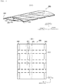
FIG. 9(A) is a side view of avibrating device 101 employing a conventional configuration, andFIG. 9(B) is a back vide of thevibrating device 101. Thevibrating device 101 includes apiezoelectric film 102, adiaphragm 103 andframe members diaphragm 103 and thepiezoelectric film 102 have rectangular shapes elongated in a length direction and a width direction when seen from a thickness direction. Thepiezoelectric film 102 is cut out from a PLLA (poly-L-lactic acid) film subjected to extension processing in a direction of 45° which is the length direction with respect to an extension direction indicated by arrows inFIG. 9(B) . Thepiezoelectric film 102 is cut out in this way to generate a stretch and contraction in the length direction with application of a voltage. Theframe members piezoelectric film 102 in the length direction. Vicinities of both ends of thediaphragm 103 in the length direction are connected to thepiezoelectric film 102 with theframe members diaphragm 103. Further, thediaphragm 103 warps such that a vicinity of center of thediaphragm 103 in the length direction is apart from thepiezoelectric film 102, and theframe members piezoelectric film 102 to an outside of the length direction via theframe members vibrating device 101, thepiezoelectric film 102 vibrates in the length direction when an alternating electric field is applied to thepiezoelectric film 102, and a warp amount of thediaphragm 103 fluctuates a warp amount accompanying this vibration. - Patent Document 1: International Publication No.
2012/157691 Pamphlet - When the haptics device (tactile sense presenting device) is configured by using the vibrating device illustrated in
FIG. 9 , a pressing force in the thickness direction is transmitted to the diaphragm in response to a touch operation. Then, the diaphragm is pushed by a pressing force, and the diaphragm flattens. When the diaphragm flattens, the diaphragm and the piezoelectric film become parallel, and, even when the piezoelectric film is vibrated in the length direction, the diaphragm hardly warps. - Hence, it is difficult to give a tactile sense feedback to the user. To prevent the diaphragm from being pushed and flattened, the diaphragm may be made thick and rigidity of the diaphragm may be improved.
- However, in this case, the warp amount of the diaphragm becomes small and it is difficult to give a tactile sense feedback to the user.
- It is therefore an object of the present invention to provide a vibrating device and a tactile sense presenting device which can warp a diaphragm in a thickness direction from a flat state and can easily increase a warp amount of the diaphragm.
- A vibrating device according to the present invention includes: a diaphragm which warps in a thickness direction; a film at least part of which has an inverse piezoelectric effect, which is connected to the diaphragm and which is stretched in a direction crossing the diaphragm from a connection position with the diaphragm; and a spacer which secures a gap between the diaphragm and the film at a position apart from the connection position.
- According to this configuration, the spacer is provided, so that, irrespectively of a state of the diaphragm, the film is stretched in the direction crossing the diaphragm and a gap between the diaphragm and the film is maintained. Consequently, it is possible to reliably warp the diaphragm in the thickness direction by driving the film even in a flat state of the diaphragm. Further, even when the diaphragm is made thin and less rigid, a gap between the diaphragm and the film is not crashed.
- Consequently, it is possible to make the diaphragm thin and less rigid and increase the warp amount of the diaphragm.
- The spacer is preferably provided between the diaphragm and the film and is in contact with the diaphragm and the film at all times. According to this configuration, the spacer can be sandwiched between and held by the diaphragm and the film.
- The spacer preferably includes a base portion which is provided at a side of the film, and a plurality of protrusion portions which is provided at a side of the diaphragm and protrudes in a thickness direction from the base portion. According to this configuration, it is possible to reduce a contact area between the diaphragm and the spacer. Consequently, it is possible to prevent attenuation of vibration when the diaphragm is pushed by a finger or the like above the spacer.
- A plurality of the spacers is preferably aligned in a length direction orthogonal to the thickness direction. The diaphragm causes such a harmonic that a contact position with the spacer becomes a node, and the harmonic can be set to an adequate frequency according to the number and positions of spacers. Generally, a frequency of vibration which is good as a tactile sense feedback for a finger (which means high sensitivity) is 100 Hz to 300 Hz. Consequently, a vibrating device whose resonance frequency is less than 100 Hz can adjust the harmonic of the vibration caused by the diaphragm to a frequency of 100 Hz to 300 Hz by adjusting the numbers and the positions of the spacers.
- The diaphragm may have a flat shape in a state where the film does not cause the inverse piezoelectric effect. Consequently, it is possible to use the vibrating device for a wide range of use.
- The film may include a chiral polymer film or a polyvinylidene fluoride film.
- Further, a tactile sense presenting device according to the present invention includes: the vibrating device; a detecting unit which is attached to the diaphragm and detects a touch operation; and a control unit which, when the detecting unit detects the touch operation, applies a drive voltage to the piezoelectric film.
- The tactile sense presenting device employing such a configuration can present a tactile sense feedback to an operator by vibrating the diaphragm to reliably warp in the thickness direction even when the diaphragm is flattened by a pressing force accompanying a touch operation.
- According to the present invention, the vibrating device and the tactile sense presenting device can reliably warp the diaphragm in the thickness direction from a flat state of the diaphragm.
-
-
FIG. 1 is a perspective view of and a plan view of a bottom surface side of a tactile sense presenting device according to a first embodiment. -
FIG. 2 is a perspective view of a spacer according to the first embodiment. -
FIG. 3 is a side view illustrating a vibration mode of a vibrating device according to the first embodiment. -
FIG. 4 is a side view of a vibrating device according to a second embodiment. -
FIG. 5 is a perspective view and a side view of a vibrating device according to a third embodiment. -
FIG. 6 is a perspective view and a side view of a vibrating device according to a fourth embodiment. -
FIG. 7 is a side view illustrating a vibration mode of a harmonic produced in the vibrating device according to the third and fourth embodiments. -
FIG. 8 is a perspective view and a side view of a vibrating device according to a fifth embodiment. -
FIG. 9 is a view for explaining a conventional structure of a vibrating device. - A plurality of modes for carrying out the present invention will be described by using some specific examples with reference to the drawings. Each embodiment is exemplary, and components described in different embodiments may be naturally partially replaced or combined.
-
FIG. 1(A) is a perspective view of a tactilesense presenting device 10 according to the first embodiment of the present invention.FIG. 1(B) is a plan view illustrating the tactilesense presenting device 10 from a bottom surface side. - The tactile
sense presenting device 10 composes a keyboard of a touch sensor type. The tactilesense presenting device 10 includes acontrol unit 11, adriving unit 12, avibrating device 20 and atouch panel 30. In addition, the tactilesense presenting device 10 may include a switch of a sheet shape such as a membrane switch in place of thetouch panel 30, yet a key position to be displayed or an indication can be arbitrarily changed by using thetouch panel 30. - The vibrating
device 20 and thetouch panel 30 are thin in a thickness direction, and are stacked in the thickness direction. Thetouch panel 30 is disposed at a top panel side in the thickness direction with respect to the vibratingdevice 20. Thetouch panel 30 includes a plurality oftouch sensors 31 exposed on the top panel of the tactilesense presenting device 10. A plurality oftouch sensors 31 is disposed at positions meeting a key alignment of the keyboard. Eachtouch sensor 31 outputs a detection signal to thecontrol unit 11 when detecting a user's touch operation. Eachtouch sensor 31 corresponds to a touch detecting unit recited in the claims. - The
control unit 11 outputs a control signal to the drivingunit 12 when receiving an input of the detection signal from one of thetouch sensors 31. The drivingunit 12 outputs a drive voltage to the vibratingdevice 20 when receiving an input of the control signal from thecontrol unit 11. - The vibrating
device 20 includes adiaphragm 21, apiezoelectric film 22 and aspacer 23. - The
diaphragm 21 is made of an elastically deformable material such as an acrylic resin PMMA. In addition, other materials such as a metal plate, PET, polycarbonate (PC), PLLA and glass may be used for thediaphragm 21. Thediaphragm 21 is disposed at the top panel side in the thickness direction with respect to thepiezoelectric film 22. Thediaphragm 21 has a rectangular shape when seen from the thickness direction, and has short sides which lie along a length direction and long sides which lie along a width direction. Further, thediaphragm 21 is curved protruding toward the top plane side in the thickness direction and recessing toward the bottom surface side in the thickness direction when seen from the width direction. The top panel of thediaphragm 21 is jointed to thetouch panel 30 with an adhesive or the like interposed therebetween. Thediaphragm 21 has a flat shape curved when seen from the width direction, and therefore thetouch panel 30 also has a shape curved when seen from the width direction similar to thediaphragm 21. - The
piezoelectric film 22 has a property that thepiezoelectric film 22 causes vibration in a planar direction when electrically driven, and corresponds to a "film" recited in the claims. Thepiezoelectric film 22 is composed by providing electrodes which are not illustrated to both of entire principal surfaces of the film made of a piezoelectric material having piezoelectricity. The piezoelectric material of thepiezoelectric film 22 is, for example, poly-L-lactic acid (PLLA) which is chiral polymers, and is desirably polyvinylidene fluoride (PVDF). When being composed of PLLA, thepiezoelectric film 22 is cut out from a film extended in a main extension direction indicated by an outlined arrow inFIG. 2(B) in a direction of approximately 45° which is the length direction with respect to the main extension direction. - Consequently, the
piezoelectric film 22 can have piezoelectricity for allowing thepiezoelectric film 22 to stretch and contract in the length direction. - In addition to the piezoelectric film, optional films may be adopted for the "film" as long as the films have the property that the films cause vibration in the planar direction when electrically driven. For example, the "film" can be composed as a composite film or an electroactive film. The electroactive film is a film which causes a stress or displacement in the planar direction when electrically driven. The composite film is a film formed by adding a piezoelectric film, the electroactive film or piezoelectric ceramics to a base material such as a resin film. The composite film or the electroactive film can be composed of a piezoelectric film, piezoelectric ceramics, an electrostriction film, an electret film, an electrically driven elastomer, a urethane rubber, a silicon rubber, a fluororubber, a nitrile rubber, a diene rubber or a liquid crystal elastomer.
- The
piezoelectric film 22 is disposed at the bottom surface side in the thickness direction with respect to thediaphragm 21. Thepiezoelectric film 22 is connected to vicinities of both ends of thediaphragm 21 in the length direction at the bottom surface side of thediaphragm 21 curved in a recess shape. Both ends of thepiezoelectric film 22 and thediaphragm 21 in the length direction are fixed ends 24. That is, thepiezoelectric film 22 is stretched between the two fixed ends 24. The vibratingdevice 20 and the tactilesense presenting device 10 are supported on an installation surface of a table or the like near the two fixed ends 24. - The
piezoelectric film 22 is stretched at the fixed ends 24 in a direction crossing a bottom surface of thediaphragm 21. Hence, a tensile force transmits from thepiezoelectric film 22 to thediaphragm 21, and therefore thediaphragm 21 elastically deforms warping in the thickness direction. Thus, thediaphragm 21 and thepiezoelectric film 22 compose the vibratingdevice 20 which is formed in a bow shape when seen from the width direction. Further, thespacer 23 is provided in a gap between thediaphragm 21 and thepiezoelectric film 22 and near a center between thediaphragm 21 and thepiezoelectric film 22 in the length direction to secure a gap of a predetermined interval between thediaphragm 21 and thepiezoelectric film 22. -
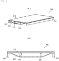
FIG. 2 is a perspective view of thespacer 23. - The
spacer 23 is made of metal, PET or polycarbonate (PC), for example. Thespacer 23 preferably has high rigidity to prevent attenuation of vibrations of thediaphragm 21 and thepiezoelectric film 22, and may be made of a material of a higher elastic modulus than those of thediaphragm 21 and thepiezoelectric film 22. Thespacer 23 is sandwiched between and held by thediaphragm 21 and thepiezoelectric film 22, and is preferably fixed to at least one of thediaphragm 21 and thepiezoelectric film 22 with an adhesive or the like interposed therebetween. Further, thespacer 23 includes abase portion 25 and a plurality ofprotrusion portions 26. Thebase portion 25 is a portion which is provided at the side of thepiezoelectric film 22 and is elongated in the width direction. A plurality ofprotrusion portions 26 is portions which are provided at the side of thediaphragm 21, and is provided to protrude from a top panel of thebase portion 25 to the thickness direction. By providing theprotrusion portions 26 at a top panel side of thespacer 23, it is possible to reduce a contact area between thediaphragm 21 and thespacer 23. Consequently, even when a finger or the like presses the vicinity of the center of thediaphragm 21 in the length direction, i.e., a portion directly above thespacer 23, it is possible to prevent significant attenuation of vibration. In addition, theprotrusion portions 26 are more preferably provided at positions facing a frame portion between thetouch sensors 31 on thetouch panel 30. -
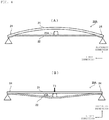
FIG. 3(A) is a side view illustrating a vibration mode of the vibratingdevice 20 in a state where a pressing force is not applied. - The
spacer 23 is disposed near the center between thepiezoelectric film 22 and thediaphragm 21 in the length direction, and is in contact with a lower surface of thediaphragm 21 and an upper surface of thepiezoelectric film 22. A dimension of thespacer 23 in the thickness direction is set to a slightly larger dimension than an interval near the center between thediaphragm 21 and thepiezoelectric film 22 in the length direction in case where thespacer 23 is not provided. Hence, when thepiezoelectric film 22 is not driven, thespacer 23 pushes thepiezoelectric film 22 downward in the thickness direction, and thepiezoelectric film 22 is curved protruding downward at a contact position with thespacer 23. - When an alternating electric field is applied to the
piezoelectric film 22 to drive thefilm 22, thepiezoelectric film 22 repeatedly contracts in the length direction. Then, a tensile force T1 transmitting from thepiezoelectric film 22 to thediaphragm 21 cyclically increases. Thus, a force component T2 of the tensile force T1 in a direction vertical to a surface of thefixed end 24 also cyclically increases. Therefore, as indicated by dotted lines inFIG. 3(A) , a warp amount of thediaphragm 21 cyclically increases. That is, the vicinity of the center of thediaphragm 21 in the length direction is cyclically displaced upward. Thus, thespacer 23 is cyclically displaced upward to maintain a state where thespacer 23 keeps contact with thediaphragm 21, and an angle at which thepiezoelectric film 22 is curved near the center in the length direction is cyclically reduced. -
FIG. 3(B) is a side view for explaining a vibration mode of the vibratingdevice 20 in a state where a pressing force produced by a touch operation or the like is applied. - In a state where a pressing force T3 of the finger or the like which performs the touch operation is applied to the
diaphragm 21 and thediaphragm 21 is pushed in a roughly flat shape, an elastic force of the vibratingdevice 20 produces a reaction force T4 with respect to the pressing force T3 and works on the finger or the like. In this state, thespacer 23 is pushed downward together with thediaphragm 21, and thepiezoelectric film 22 bends more compared to a case where the pressing force T3 is not applied. That is, even when the pressing force T3 is applied to thediaphragm 21 and thediaphragm 21 is pushed in a roughly flat shape, thespacer 23 prevents the gap between thediaphragm 21 and thepiezoelectric film 22 from being crashed, and thepiezoelectric film 22 is kept in a state where thepiezoelectric film 22 is stretched in the direction crossing the surface of thefixed end 24. Consequently, even when thediaphragm 21 is in a flat state, the force component T2 of the tensile force T1 works in a direction vertical to the surface of thefixed end 24. - Hence, even when the alternating electric field is applied to the
piezoelectric film 22 and is driven in this state, the tensile force T1 transmitting from thepiezoelectric film 22 to thediaphragm 21 and the force component T2 of the tensile force T1 cyclically increase, and thediaphragm 21 cyclically warps significantly. Thus, the reaction force T4 transmitting from thediaphragm 21 to the finger or the like which pushes thediaphragm 21 cyclically fluctuates, so that it is possible to present a tactile sense feedback to a user who performs the touch operation. Consequently, even if a key position displayed on thetouch panel 30 is arbitrarily changed, and this key position is touched, the user can have a clicking feeling, so that it is possible to improve operability and an operational feeling of the touch keyboard. - Thus, in the tactile sense presenting device 1 and the vibrating
device 20, thespacer 23 prevents the gap between thediaphragm 21 and thepiezoelectric film 22 from being crashed. - Consequently, it is possible to make the
diaphragm 21 thin, suppress rigidity of thediaphragm 21 and make the warp amount of thediaphragm 21 large compared to the conventional technique. - In addition, in the present embodiment, both ends of the
diaphragm 21 and thepiezoelectric film 22 in the length direction are connected as the fixed ends 24, so that it is possible to suppress the number of members which compose the vibrating device. In this regard, the tactile sense presenting device and the vibrating device according to the present invention may employ different configurations from the above configurations. - For example, only one end sides of the diaphragm and the piezoelectric film in the length direction may be directly connected, and the other end sides in the length direction may be connected with a support member interposed therebetween.
- Further, in the present embodiment, the
piezoelectric film 22 which is a single layer is configured to be stretched on thediaphragm 21. - However, the
piezoelectric film 22 may be pasted on a filter (exciter film) which is a base material such as a resin film, and stretched on thediaphragm 21 to compose the tactile sense presenting device and the vibrating device according to the present invention. Further, piezoelectric ceramics may be added to the exciter film and the exciter film is stretched on thediaphragm 21 to compose the tactile sense presenting device and the vibrating device according to the present invention. In this case, a pair of exciter films may be prepared, one end of each exciter film may be connected to the piezoelectric ceramics, and the other end of each exciter film may be connected to thediaphragm 21. Further, a plurality of pairs of exciter films may be prepared, and configured to be connected with one piezoelectric ceramics. - Furthermore, in the present embodiment, the
spacer 23 is provided with thebase portion 25 and theprotrusion portions 26, yet, for example, thespacer 23 may have a shape without theprotrusion portions 26. In this regard, providing theprotrusion portions 26 can reduce a contact area between thespacer 23 and thediaphragm 21. When the contact area between thespacer 23 and thediaphragm 21 is smaller, thespacer 23 is prevented from constraining vibration of thediaphragm 21 and thediaphragm 21 can be vibrated better. Further, theprotrusion portions 26 are not limited to columnar shapes illustrated inFIG. 2 and may have other shapes such as semispherical shapes or conical shapes. - Furthermore, additionally, the
protrusion portions 26 may have a blade back shape (blade shape) protruding toward thediaphragm 21 in the thickness direction and stretching in an intra-plane direction. Still further, theprotrusion portions 26 may have cross sections of polygonal shapes such as quadrangular prism shapes. Moreover, thebase portion 25 of thespacer 23 may have a shape different from a cuboid shape. - Besides, a configuration where, even when the
piezoelectric film 22 is not driven, thespacer 23 is in contact with thediaphragm 21 and thepiezoelectric film 22 and a tension is applied from thespacer 23 to thepiezoelectric film 22 has been described in the present embodiment. - However, the present invention is not limited to this example. For example, the
spacer 23 may be set to the substantially same height as the interval between thediaphragm 21 and thepiezoelectric film 22 in case where thepiezoelectric film 22 is not driven. In this case, even in a state where thespacer 23 is in contact with thepiezoelectric film 22 and thepiezoelectric film 22 when thepiezoelectric film 22 is not driven, a tension is not applied from thespacer 23 to thepiezoelectric film 22. - Consequently, compared to a case where the tension is applied from the
spacer 23 to thepiezoelectric film 22 at all times, it is possible to reduce a load applied to thepiezoelectric film 22 and prevent shape deterioration and characteristics deterioration of thepiezoelectric film 22. - Next, a vibrating device according to a second embodiment of the present invention will be described.
-
FIG. 4(A) is a side view illustrating a state where a pressing force is not applied to a vibratingdevice 20A according to the second embodiment. The vibratingdevice 20A includes adiaphragm 21, apiezoelectric film 22 and aspacer 23A. Thespacer 23A is set to a dimension smaller than an interval between thediaphragm 21 and thepiezoelectric film 22 in case where thespacer 23A is not provided, and is fixed to the piezoelectric film 22 (or diaphragm 21) via an adhesive or the like. Hence, in a state where the pressing force is not applied to the vibratingdevice 20A, thespacer 23A is not in contact with thediaphragm 21 and thepiezoelectric film 22 is flat. -
FIG. 4(B) is a side view illustrating a state where the pressing force is applied to the vibratingdevice 20A according to the second embodiment. In a state where a relatively great pressing force T3 is applied from a finger or the like which performs a touch operation to thediaphragm 21 and thediaphragm 21 is pushed in a roughly flat shape, thespacer 23A is in contact with both of thediaphragm 21 and thepiezoelectric film 22, and pushes thepiezoelectric film 22 downward. Thus, thepiezoelectric film 22 is curved protruding downward at a contact position with thespacer 23A. Hence, thespacer 23 prevents the gap between thediaphragm 21 and thepiezoelectric film 22 from being crashed, and, even when thediaphragm 21 flattens by the pressing force T3, thepiezoelectric film 22 is kept in a state where thepiezoelectric film 22 is stretched in the direction crossing a surface of afixed end 24. - Consequently, the vibrating
device 20A can also vibrate thediaphragm 21 repeatedly warping by driving thepiezoelectric film 22 in a state where the pressing force T3 is applied to thediaphragm 21 from the finger or the like which performs a touch operation to push thediaphragm 21 in a roughly flat shape. Consequently, even when the tactile sense presenting device is composed by using the vibratingdevice 20A, it is possible to present a tactile sense feedback to a user who performs the touch operation. - Further, according to a configuration where the spacer is not in contact with the diaphragm at a normal time as in the present embodiment, when the finger or the like which performs the touch operation touches the diaphragm or the touch panel, vibration of the diaphragm is not constrained by the spacer.
- Consequently, a time taken by the vibration of the diaphragm to rise from zero to a desired amplitude is short. Consequently, it is possible to give a more reliably tactile sense feedback to an operator who performs the touch operation.
- Next, a vibrating device according to a third embodiment of the present invention will be described.
-
FIG. 5(A) is a perspective view of a vibratingdevice 20B according to the third embodiment, andFIG. 5(B) is a side view of the vibratingdevice 20B according to the third embodiment. - The vibrating
device 20B includes adiaphragm 21B, apiezoelectric film 22B, aspacer 23B and fixedportions 24B. Vicinities of both ends of thediaphragm 21B and thepiezoelectric film 22B in a length direction are connected with each other, and an initial shape of thediaphragm 21B and a tensile force of thepiezoelectric film 22B are set such that thediaphragm 21B maintains a flat shape without curving in a state where the both ends are connected. More specifically, an initial shape of thediaphragm 21B in a state where thediaphragm 21B is not connected with thepiezoelectric film 22B is formed in a curved shape protruding downward in advance. Further, the tensile force of thepiezoelectric film 22B is set such that the tensile force applied by thepiezoelectric film 22B and an external force applied by thespacer 23B deform thediaphragm 21B in a flat shape. - Near the both ends of the
diaphragm 21B and thepiezoelectric film 22B which are connected, the fixedportions 24B are provided protruding downward in a thickness direction of the vibratingdevice 20B. The fixedportions 24B are supported on an installation surface of a table or the like, and prevent thediaphragm 21B and thepiezoelectric film 22B from directly contacting the installation surface. - In the vibrating
device 20B employing such a configuration, too, thespacer 23B is disposed near the center between thepiezoelectric film 22B and thediaphragm 21B in the length direction, and comes into contact with a lower surface of thediaphragm 21B and an upper surface of thepiezoelectric film 22B to secure a gap of a predetermined interval between thediaphragm 21B and thepiezoelectric film 22B. Hence, thespacer 23B pushes thepiezoelectric film 22B downward in the thickness direction, and thepiezoelectric film 22B is curved protruding downward at a contact position with thespacer 23B. - Thus, even when the
diaphragm 21B is in a flat state, thepiezoelectric film 22B is stretched in a direction crossing a surface of thediaphragm 21B. Consequently, thediaphragm 21B cyclically warps by driving thepiezoelectric film 22B, so that it is possible to present a tactile sense feedback to a user who performs a touch operation. Thus, by providing thespacer 23B, the vibratingdevice 20B can warp thediaphragm 21B even when it is not in a curved shape. Consequently, it is possible to increase the degree of freedom of the shape of thediaphragm 21B. - Next, a vibrating device according to a fourth embodiment of the present invention will be described.
-
FIG. 6(A) is a perspective view of a vibratingdevice 20C according to the fourth embodiment, andFIG. 6(B) is a side view of the vibratingdevice 20C according to the fourth embodiment. - The vibrating
device 20C includes adiaphragm 21C, apiezoelectric film 22C,spacers portions 25C. Vicinities of both ends of thediaphragm 21C and thepiezoelectric film 22C in a length direction are connected with each other, and an initial shape of thediaphragm 21C and a tensile force of thepiezoelectric film 22C are set such that thediaphragm 21C maintains a flat shape without curving in a state where the both ends are connected. Near the both ends of thediaphragm 21C and thepiezoelectric film 22C which are connected, the fixedportions 25C are configured to protrude downward in a thickness direction of the vibratingdevice 20C. Thespacers device 20C, and come into contact with a lower surface of thediaphragm 21C and an upper surface of thepiezoelectric film 22C to secure a predetermined interval between thediaphragm 21C and thepiezoelectric film 22C. Hence, thepiezoelectric film 22C is pushed downward in a thickness direction and is curved by thespacers - The
diaphragm 21B is in a flat state in this vibratingdevice 20C, too, and thepiezoelectric film 22B is stretched in a direction crossing a surface of thediaphragm 21C. Consequently, thediaphragm 21C cyclically warps by driving thepiezoelectric film 22C, so that it is possible to present a tactile sense feedback to a user who performs a touch operation. -
FIG. 7 is a view for explaining vibrations caused by a vibratingdevice 20B according to the third embodiment and the vibratingdevice 20C according to the fourth embodiment. - The vibrating
device 20B and the vibratingdevice 20C have resonance frequencies determined according to dimensions ofdiaphragm device 20B and the vibratingdevice 20C, such vibrations that the vicinity of centers of the vibratingdevice 20B and the vibratingdevice 20C in the length direction serves as antinodes of vibration and vicinities of both ends of the vibratingdevice 20B and the vibratingdevice 20C in the length direction are fixed ends occur. Further, such a harmonic that contact positions withspacers diaphragms diaphragms - As illustrated in
FIG. 7(A) , thespacer 23B is in contact with the vicinity of the center of thediaphragm 21B in the length direction, so that the vibratingdevice 20B causes vibration of such a harmonic that this contact position serves as a node of the vibration. That is, vibration of a second harmonic whose 1 wavelength is the dimension of thediaphragm 21B in the length direction is superimposed on the vibration of the vibratingdevice 20B. - Meanwhile, as illustrated in
FIG. 7(B) , thespacers diaphragm 21C, so that the vibratingdevice 20C causes vibration of such a harmonic that connection positions with thespacers diaphragm 21C in the length direction is superimposed on the vibration of the vibratingdevice 20C. - Hence, the vibrating
device 20B according to the third embodiment and the vibratingdevice 20C according to the fourth embodiment differ in frequencies of harmonics produced by thediaphragms diaphragms diaphragms diaphragms diaphragms - Next, a vibrating device according to a fifth embodiment of the present invention will be described.
-
FIG. 8(A) is a perspective view of a vibratingdevice 20D according to the fifth embodiment, andFIG. 8(B) is a side view of the vibratingdevice 20D according to the fifth embodiment. - The vibrating
device 20D includes adiaphragm 21D, a plurality ofpiezoelectric films 22D and aspacer 23D. A plurality ofpiezoelectric films 22D has stripe shapes whose dimensions in a width direction are short and whose dimensions in a length direction are long, and are aligned in the width direction in parallel to each other. A plurality ofpiezoelectric films 22D has the substantially same dimension in the length direction as that of thediaphragm 21D, and is provided with fixed ends 24D which are connected with thediaphragm 21D, near both ends in the length direction. Thespacer 23D is in contact with a lower surface of thediaphragm 21D and upper surfaces of a plurality ofpiezoelectric films 22D, extends in the width direction over a plurality ofpiezoelectric films 22D and secures a predetermined interval between thediaphragm 21D and a plurality ofpiezoelectric films 22D. Hence, a plurality ofpiezoelectric films 22D is pushed downward in a thickness direction and is curved by thespacer 23D. - In the vibrating
device 20D, the shape of eachpiezoelectric film 22D is a strip shape which is long in the length direction. Therefore, when driven, eachpiezoelectric film 22D stretches or contracts the most in the length direction. Consequently, by vibrating thediaphragm 21D by using a plurality of thesepiezoelectric films 22D, it is possible to effectively vibrate thediaphragm 21D. Further, the vibratingdevice 20D is also provided with thespacer 23D similar to each of the above-described embodiments, so that it is possible to vibrate thediaphragm 21D even in a state where thediaphragm 21D is pushed. Consequently, even when the tactile sense presenting device is composed by using the vibratingdevice 20A, it is possible to present a tactile sense feedback to a user who performs the touch operation. - In addition, when a plurality of piezoelectric films is provided as in the present embodiment, a single spacer may be disposed across a plurality of piezoelectric films as described above, and, in addition, a plurality of shorter spacers may be individually disposed on piezoelectric films, respectively. By disposing a plurality of spacers on a plurality of piezoelectric films, it is possible to adjust a tension to be applied to each piezoelectric film, and more effectively vibrate the diaphragm, too.
- Further, similar to the configuration illustrated in
FIG. 6 , according to the configuration according to the present embodiment, too, a plurality of spacers may be aligned in the length direction of each piezoelectric film. - The present invention can be carried out as described above, yet the present invention can be carried out while employing configurations other than the above configurations as long as these configurations correspond to the claims. For example, the vibrating device according to the present invention may be used for other devices than the tactile sense presenting device such as a flat speaker.
-
- 10:
- TACTILE SENSE PRESENTING DEVICE
- 11:
- CONTROL UNIT
- 12:
- DRIVING UNIT
- 20, 20B, 20C:
- VIBRATING DEVICE
- 21, 21B, 21C:
- DIAPHRAGM
- 22, 22B, 22C:
- PIEZOELECTRIC FILM
- 23, 23A, 23B, 23C, 24C:
- SPACER
- 24:
- FIXED END
- 24B, 25C:
- FIXED PORTION
- 25:
- BASE PORTION
- 26:
- PROTRUSION PORTION
- 30:
- TOUCH PANEL
- 31:
- TOUCH SENSOR
Claims (7)
- A vibrating device comprising:a diaphragm which warps in a thickness direction;a film part of which has a property that the film causes vibration in a planar direction when electrically driven, which is connected to the diaphragm and which is stretched in a direction crossing the diaphragm from a connection position connected with the diaphragm; anda spacer which secures a gap between the diaphragm and the film at a position apart from the connection position.
- The vibrating device according to claim 1, wherein the spacer is provided between the diaphragm and the film and is in contact with the diaphragm and the film at all times.
- The vibrating device according to claim 1 or 2, wherein the spacer includes
a base portion which is provided at a side of the film, and
a plurality of protrusion portions which is provided at a side of the diaphragm and protrudes in the thickness direction from the base portion. - The vibrating device according to any one of claims 1 to 3, wherein a plurality of the spacers is aligned in a length direction orthogonal to the thickness direction.
- The vibrating device according to any one of claims 1 to 4, wherein the diaphragm has a flat shape in a state where the film does not cause an inverse piezoelectric effect.
- The vibrating device according to any one of claims 1 to 5, wherein the film includes a chiral polymer film or a polyvinylidene fluoride film.
- A tactile sense presenting device comprising:a vibrating device according to any one of claims 1 to 6;a touch detecting unit which is attached to the diaphragm and detects a touch operation; anda control unit which, when the touch detecting unit detects the touch operation, applies a drive voltage to the film.
Applications Claiming Priority (2)
| Application Number | Priority Date | Filing Date | Title |
|---|---|---|---|
| JP2014118332 | 2014-06-09 | ||
| PCT/JP2015/065983 WO2015190358A1 (en) | 2014-06-09 | 2015-06-03 | Vibrating device and haptic device |
Publications (3)
| Publication Number | Publication Date |
|---|---|
| EP3153948A1 true EP3153948A1 (en) | 2017-04-12 |
| EP3153948A4 EP3153948A4 (en) | 2018-01-10 |
| EP3153948B1 EP3153948B1 (en) | 2022-09-28 |
Family
ID=54833454
Family Applications (1)
| Application Number | Title | Priority Date | Filing Date |
|---|---|---|---|
| EP15805753.9A Active EP3153948B1 (en) | 2014-06-09 | 2015-06-03 | Vibrating device and haptic device |
Country Status (5)
| Country | Link |
|---|---|
| US (1) | US10365718B2 (en) |
| EP (1) | EP3153948B1 (en) |
| JP (1) | JP6128281B2 (en) |
| CN (1) | CN106537301B (en) |
| WO (1) | WO2015190358A1 (en) |
Families Citing this family (10)
| Publication number | Priority date | Publication date | Assignee | Title |
|---|---|---|---|---|
| WO2016204259A1 (en) * | 2015-06-17 | 2016-12-22 | 株式会社村田製作所 | Vibration device and haptic apparatus |
| CN107852554B (en) * | 2015-08-20 | 2020-12-25 | 株式会社东金 | Vibration transmission structure and piezoelectric speaker |
| WO2017057579A1 (en) * | 2015-09-30 | 2017-04-06 | 株式会社村田製作所 | Vibration device and tactile sensation presentation device |
| WO2018088340A1 (en) | 2016-11-11 | 2018-05-17 | 株式会社村田製作所 | Vibration device |
| KR102689710B1 (en) * | 2019-03-29 | 2024-07-29 | 엘지디스플레이 주식회사 | Display apparatus |
| CN112805096B (en) * | 2019-04-19 | 2022-04-12 | 株式会社村田制作所 | Vibration device |
| CN110290236B (en) * | 2019-04-23 | 2021-06-25 | 维沃移动通信有限公司 | A terminal device and vibration control method |
| CN115279505A (en) * | 2020-03-05 | 2022-11-01 | 太阳诱电株式会社 | Vibration generating device and electronic apparatus |
| CN113282162B (en) * | 2020-09-22 | 2024-03-19 | 苏州索迩电子技术有限公司 | A screen multi-touch tactile feedback device |
| WO2023092540A1 (en) * | 2021-11-29 | 2023-06-01 | 京东方科技集团股份有限公司 | Tactile feedback panel, tactile feedback method therefor, and tactile feedback device therefor |
Family Cites Families (22)
| Publication number | Priority date | Publication date | Assignee | Title |
|---|---|---|---|---|
| JPS4926890B1 (en) * | 1970-12-04 | 1974-07-12 | ||
| JPS5215972B2 (en) * | 1974-02-28 | 1977-05-06 | ||
| US4045695A (en) * | 1974-07-15 | 1977-08-30 | Pioneer Electronic Corporation | Piezoelectric electro-acoustic transducer |
| GB1593271A (en) * | 1976-09-21 | 1981-07-15 | Standard Telephones Cables Ltd | Electro-acoustic transducers |
| DE4119955C2 (en) * | 1991-06-18 | 2000-05-31 | Danfoss As | Miniature actuator |
| JP2894276B2 (en) * | 1996-05-02 | 1999-05-24 | 日本電気株式会社 | Piezo acoustic transducer |
| US6060811A (en) * | 1997-07-25 | 2000-05-09 | The United States Of America As Represented By The United States National Aeronautics And Space Administration | Advanced layered composite polylaminate electroactive actuator and sensor |
| US5867302A (en) * | 1997-08-07 | 1999-02-02 | Sandia Corporation | Bistable microelectromechanical actuator |
| CA2396260C (en) * | 2000-01-07 | 2007-09-11 | Lewis Athanas | Mechanical-to-acoustical transformer and multi-media flat film speaker |
| US6822635B2 (en) * | 2000-01-19 | 2004-11-23 | Immersion Corporation | Haptic interface for laptop computers and other portable devices |
| DE10144634A1 (en) * | 2001-09-11 | 2003-04-10 | Trw Automotive Electron & Comp | operating system |
| JP4311905B2 (en) * | 2002-02-05 | 2009-08-12 | オリンパス株式会社 | Optical system |
| JP4869568B2 (en) * | 2004-06-14 | 2012-02-08 | ソニー株式会社 | Input device and electronic device |
| US20070063982A1 (en) * | 2005-09-19 | 2007-03-22 | Tran Bao Q | Integrated rendering of sound and image on a display |
| EP2202619A1 (en) * | 2008-12-23 | 2010-06-30 | Research In Motion Limited | Portable electronic device including tactile touch-sensitive input device and method of controlling same |
| JP2011076725A (en) * | 2009-09-29 | 2011-04-14 | Fujifilm Corp | Piezoelectric mems element, and manufacturing method thereof |
| KR101133296B1 (en) * | 2009-10-12 | 2012-04-04 | 삼성전기주식회사 | Haptic feedback actuator, haptic feedback device and electronic device |
| US8692646B2 (en) * | 2011-04-05 | 2014-04-08 | Kang Won LEE | Piezoresistive type touch panel; manufacturing method thereof; and display device, touch pad, pressure sensor, touch sensor, game console and keyboard having the panel |
| JP5134706B2 (en) * | 2011-05-16 | 2013-01-30 | 日本写真印刷株式会社 | Curved touch panel, manufacturing method thereof, and display device with curved touch panel |
| JP5708799B2 (en) * | 2011-05-17 | 2015-04-30 | 株式会社村田製作所 | Flat speaker and AV equipment |
| WO2016027668A1 (en) * | 2014-08-22 | 2016-02-25 | 株式会社村田製作所 | Tactile sensation presentation device |
| WO2017057579A1 (en) * | 2015-09-30 | 2017-04-06 | 株式会社村田製作所 | Vibration device and tactile sensation presentation device |
-
2015
- 2015-06-03 JP JP2016527757A patent/JP6128281B2/en active Active
- 2015-06-03 WO PCT/JP2015/065983 patent/WO2015190358A1/en not_active Ceased
- 2015-06-03 CN CN201580030436.8A patent/CN106537301B/en active Active
- 2015-06-03 EP EP15805753.9A patent/EP3153948B1/en active Active
-
2016
- 2016-12-02 US US15/367,891 patent/US10365718B2/en active Active
Also Published As
| Publication number | Publication date |
|---|---|
| CN106537301B (en) | 2019-09-10 |
| JP6128281B2 (en) | 2017-05-17 |
| US10365718B2 (en) | 2019-07-30 |
| EP3153948A4 (en) | 2018-01-10 |
| WO2015190358A1 (en) | 2015-12-17 |
| US20170083099A1 (en) | 2017-03-23 |
| JPWO2015190358A1 (en) | 2017-04-20 |
| CN106537301A (en) | 2017-03-22 |
| EP3153948B1 (en) | 2022-09-28 |
Similar Documents
| Publication | Publication Date | Title |
|---|---|---|
| EP3153948B1 (en) | Vibrating device and haptic device | |
| US11455038B2 (en) | Vibration structure, vibration device, and tactile sense presentation device | |
| CN105706029B (en) | tactile cueing device | |
| US10664054B2 (en) | Vibrating device | |
| JP6187703B2 (en) | Vibration device | |
| CN112805096B (en) | Vibration device | |
| US11011694B2 (en) | Vibrating device and tactile sense presenting device | |
| JP6237959B2 (en) | Vibration device and tactile presentation device | |
| US20230001451A1 (en) | Vibration structure, vibration device, and tactile sense presentation device | |
| JP6183557B2 (en) | Vibration device | |
| WO2021177268A1 (en) | Vibration device | |
| JP6504011B2 (en) | Tactile presentation device | |
| WO2016027667A1 (en) | Vibrating body and tactile sensation presentation keyboard | |
| JP6311464B2 (en) | Tactile presentation device | |
| JP6288387B2 (en) | Vibration device and tactile presentation device | |
| JP2016053889A (en) | Tactile sense presentation device | |
| WO2023021937A1 (en) | Vibration device | |
| JP6590082B2 (en) | Vibration device |
Legal Events
| Date | Code | Title | Description |
|---|---|---|---|
| STAA | Information on the status of an ep patent application or granted ep patent |
Free format text: STATUS: THE INTERNATIONAL PUBLICATION HAS BEEN MADE |
|
| PUAI | Public reference made under article 153(3) epc to a published international application that has entered the european phase |
Free format text: ORIGINAL CODE: 0009012 |
|
| STAA | Information on the status of an ep patent application or granted ep patent |
Free format text: STATUS: REQUEST FOR EXAMINATION WAS MADE |
|
| 17P | Request for examination filed |
Effective date: 20161202 |
|
| AK | Designated contracting states |
Kind code of ref document: A1 Designated state(s): AL AT BE BG CH CY CZ DE DK EE ES FI FR GB GR HR HU IE IS IT LI LT LU LV MC MK MT NL NO PL PT RO RS SE SI SK SM TR |
|
| AX | Request for extension of the european patent |
Extension state: BA ME |
|
| DAV | Request for validation of the european patent (deleted) | ||
| DAX | Request for extension of the european patent (deleted) | ||
| A4 | Supplementary search report drawn up and despatched |
Effective date: 20171212 |
|
| RIC1 | Information provided on ipc code assigned before grant |
Ipc: G06F 3/01 20060101ALI20171206BHEP Ipc: H01L 41/08 20060101ALI20171206BHEP Ipc: G06F 3/041 20060101AFI20171206BHEP Ipc: B06B 1/06 20060101ALI20171206BHEP Ipc: H01L 41/053 20060101ALI20171206BHEP |
|
| STAA | Information on the status of an ep patent application or granted ep patent |
Free format text: STATUS: EXAMINATION IS IN PROGRESS |
|
| 17Q | First examination report despatched |
Effective date: 20200103 |
|
| GRAP | Despatch of communication of intention to grant a patent |
Free format text: ORIGINAL CODE: EPIDOSNIGR1 |
|
| STAA | Information on the status of an ep patent application or granted ep patent |
Free format text: STATUS: GRANT OF PATENT IS INTENDED |
|
| INTG | Intention to grant announced |
Effective date: 20220422 |
|
| GRAS | Grant fee paid |
Free format text: ORIGINAL CODE: EPIDOSNIGR3 |
|
| GRAA | (expected) grant |
Free format text: ORIGINAL CODE: 0009210 |
|
| STAA | Information on the status of an ep patent application or granted ep patent |
Free format text: STATUS: THE PATENT HAS BEEN GRANTED |
|
| AK | Designated contracting states |
Kind code of ref document: B1 Designated state(s): AL AT BE BG CH CY CZ DE DK EE ES FI FR GB GR HR HU IE IS IT LI LT LU LV MC MK MT NL NO PL PT RO RS SE SI SK SM TR |
|
| REG | Reference to a national code |
Ref country code: GB Ref legal event code: FG4D |
|
| REG | Reference to a national code |
Ref country code: CH Ref legal event code: EP |
|
| REG | Reference to a national code |
Ref country code: DE Ref legal event code: R096 Ref document number: 602015080988 Country of ref document: DE |
|
| REG | Reference to a national code |
Ref country code: AT Ref legal event code: REF Ref document number: 1521665 Country of ref document: AT Kind code of ref document: T Effective date: 20221015 |
|
| REG | Reference to a national code |
Ref country code: IE Ref legal event code: FG4D |
|
| REG | Reference to a national code |
Ref country code: LT Ref legal event code: MG9D |
|
| PG25 | Lapsed in a contracting state [announced via postgrant information from national office to epo] |
Ref country code: SE Free format text: LAPSE BECAUSE OF FAILURE TO SUBMIT A TRANSLATION OF THE DESCRIPTION OR TO PAY THE FEE WITHIN THE PRESCRIBED TIME-LIMIT Effective date: 20220928 Ref country code: RS Free format text: LAPSE BECAUSE OF FAILURE TO SUBMIT A TRANSLATION OF THE DESCRIPTION OR TO PAY THE FEE WITHIN THE PRESCRIBED TIME-LIMIT Effective date: 20220928 Ref country code: NO Free format text: LAPSE BECAUSE OF FAILURE TO SUBMIT A TRANSLATION OF THE DESCRIPTION OR TO PAY THE FEE WITHIN THE PRESCRIBED TIME-LIMIT Effective date: 20221228 Ref country code: LV Free format text: LAPSE BECAUSE OF FAILURE TO SUBMIT A TRANSLATION OF THE DESCRIPTION OR TO PAY THE FEE WITHIN THE PRESCRIBED TIME-LIMIT Effective date: 20220928 Ref country code: LT Free format text: LAPSE BECAUSE OF FAILURE TO SUBMIT A TRANSLATION OF THE DESCRIPTION OR TO PAY THE FEE WITHIN THE PRESCRIBED TIME-LIMIT Effective date: 20220928 Ref country code: FI Free format text: LAPSE BECAUSE OF FAILURE TO SUBMIT A TRANSLATION OF THE DESCRIPTION OR TO PAY THE FEE WITHIN THE PRESCRIBED TIME-LIMIT Effective date: 20220928 |
|
| REG | Reference to a national code |
Ref country code: NL Ref legal event code: MP Effective date: 20220928 |
|
| REG | Reference to a national code |
Ref country code: AT Ref legal event code: MK05 Ref document number: 1521665 Country of ref document: AT Kind code of ref document: T Effective date: 20220928 |
|
| PG25 | Lapsed in a contracting state [announced via postgrant information from national office to epo] |
Ref country code: HR Free format text: LAPSE BECAUSE OF FAILURE TO SUBMIT A TRANSLATION OF THE DESCRIPTION OR TO PAY THE FEE WITHIN THE PRESCRIBED TIME-LIMIT Effective date: 20220928 Ref country code: GR Free format text: LAPSE BECAUSE OF FAILURE TO SUBMIT A TRANSLATION OF THE DESCRIPTION OR TO PAY THE FEE WITHIN THE PRESCRIBED TIME-LIMIT Effective date: 20221229 |
|
| PG25 | Lapsed in a contracting state [announced via postgrant information from national office to epo] |
Ref country code: SM Free format text: LAPSE BECAUSE OF FAILURE TO SUBMIT A TRANSLATION OF THE DESCRIPTION OR TO PAY THE FEE WITHIN THE PRESCRIBED TIME-LIMIT Effective date: 20220928 Ref country code: RO Free format text: LAPSE BECAUSE OF FAILURE TO SUBMIT A TRANSLATION OF THE DESCRIPTION OR TO PAY THE FEE WITHIN THE PRESCRIBED TIME-LIMIT Effective date: 20220928 Ref country code: PT Free format text: LAPSE BECAUSE OF FAILURE TO SUBMIT A TRANSLATION OF THE DESCRIPTION OR TO PAY THE FEE WITHIN THE PRESCRIBED TIME-LIMIT Effective date: 20230130 Ref country code: ES Free format text: LAPSE BECAUSE OF FAILURE TO SUBMIT A TRANSLATION OF THE DESCRIPTION OR TO PAY THE FEE WITHIN THE PRESCRIBED TIME-LIMIT Effective date: 20220928 Ref country code: CZ Free format text: LAPSE BECAUSE OF FAILURE TO SUBMIT A TRANSLATION OF THE DESCRIPTION OR TO PAY THE FEE WITHIN THE PRESCRIBED TIME-LIMIT Effective date: 20220928 Ref country code: AT Free format text: LAPSE BECAUSE OF FAILURE TO SUBMIT A TRANSLATION OF THE DESCRIPTION OR TO PAY THE FEE WITHIN THE PRESCRIBED TIME-LIMIT Effective date: 20220928 |
|
| PG25 | Lapsed in a contracting state [announced via postgrant information from national office to epo] |
Ref country code: SK Free format text: LAPSE BECAUSE OF FAILURE TO SUBMIT A TRANSLATION OF THE DESCRIPTION OR TO PAY THE FEE WITHIN THE PRESCRIBED TIME-LIMIT Effective date: 20220928 Ref country code: PL Free format text: LAPSE BECAUSE OF FAILURE TO SUBMIT A TRANSLATION OF THE DESCRIPTION OR TO PAY THE FEE WITHIN THE PRESCRIBED TIME-LIMIT Effective date: 20220928 Ref country code: IS Free format text: LAPSE BECAUSE OF FAILURE TO SUBMIT A TRANSLATION OF THE DESCRIPTION OR TO PAY THE FEE WITHIN THE PRESCRIBED TIME-LIMIT Effective date: 20230128 Ref country code: EE Free format text: LAPSE BECAUSE OF FAILURE TO SUBMIT A TRANSLATION OF THE DESCRIPTION OR TO PAY THE FEE WITHIN THE PRESCRIBED TIME-LIMIT Effective date: 20220928 |
|
| REG | Reference to a national code |
Ref country code: DE Ref legal event code: R097 Ref document number: 602015080988 Country of ref document: DE |
|
| PG25 | Lapsed in a contracting state [announced via postgrant information from national office to epo] |
Ref country code: NL Free format text: LAPSE BECAUSE OF FAILURE TO SUBMIT A TRANSLATION OF THE DESCRIPTION OR TO PAY THE FEE WITHIN THE PRESCRIBED TIME-LIMIT Effective date: 20220928 Ref country code: AL Free format text: LAPSE BECAUSE OF FAILURE TO SUBMIT A TRANSLATION OF THE DESCRIPTION OR TO PAY THE FEE WITHIN THE PRESCRIBED TIME-LIMIT Effective date: 20220928 |
|
| PG25 | Lapsed in a contracting state [announced via postgrant information from national office to epo] |
Ref country code: DK Free format text: LAPSE BECAUSE OF FAILURE TO SUBMIT A TRANSLATION OF THE DESCRIPTION OR TO PAY THE FEE WITHIN THE PRESCRIBED TIME-LIMIT Effective date: 20220928 |
|
| PLBE | No opposition filed within time limit |
Free format text: ORIGINAL CODE: 0009261 |
|
| STAA | Information on the status of an ep patent application or granted ep patent |
Free format text: STATUS: NO OPPOSITION FILED WITHIN TIME LIMIT |
|
| 26N | No opposition filed |
Effective date: 20230629 |
|
| PG25 | Lapsed in a contracting state [announced via postgrant information from national office to epo] |
Ref country code: SI Free format text: LAPSE BECAUSE OF FAILURE TO SUBMIT A TRANSLATION OF THE DESCRIPTION OR TO PAY THE FEE WITHIN THE PRESCRIBED TIME-LIMIT Effective date: 20220928 |
|
| PG25 | Lapsed in a contracting state [announced via postgrant information from national office to epo] |
Ref country code: MC Free format text: LAPSE BECAUSE OF FAILURE TO SUBMIT A TRANSLATION OF THE DESCRIPTION OR TO PAY THE FEE WITHIN THE PRESCRIBED TIME-LIMIT Effective date: 20220928 |
|
| PG25 | Lapsed in a contracting state [announced via postgrant information from national office to epo] |
Ref country code: MC Free format text: LAPSE BECAUSE OF FAILURE TO SUBMIT A TRANSLATION OF THE DESCRIPTION OR TO PAY THE FEE WITHIN THE PRESCRIBED TIME-LIMIT Effective date: 20220928 |
|
| REG | Reference to a national code |
Ref country code: CH Ref legal event code: PL |
|
| REG | Reference to a national code |
Ref country code: BE Ref legal event code: MM Effective date: 20230630 |
|
| GBPC | Gb: european patent ceased through non-payment of renewal fee |
Effective date: 20230603 |
|
| PG25 | Lapsed in a contracting state [announced via postgrant information from national office to epo] |
Ref country code: LU Free format text: LAPSE BECAUSE OF NON-PAYMENT OF DUE FEES Effective date: 20230603 |
|
| REG | Reference to a national code |
Ref country code: IE Ref legal event code: MM4A |
|
| PG25 | Lapsed in a contracting state [announced via postgrant information from national office to epo] |
Ref country code: LU Free format text: LAPSE BECAUSE OF NON-PAYMENT OF DUE FEES Effective date: 20230603 |
|
| PG25 | Lapsed in a contracting state [announced via postgrant information from national office to epo] |
Ref country code: IE Free format text: LAPSE BECAUSE OF NON-PAYMENT OF DUE FEES Effective date: 20230603 |
|
| PG25 | Lapsed in a contracting state [announced via postgrant information from national office to epo] |
Ref country code: IE Free format text: LAPSE BECAUSE OF NON-PAYMENT OF DUE FEES Effective date: 20230603 Ref country code: CH Free format text: LAPSE BECAUSE OF NON-PAYMENT OF DUE FEES Effective date: 20230630 Ref country code: GB Free format text: LAPSE BECAUSE OF NON-PAYMENT OF DUE FEES Effective date: 20230603 |
|
| PG25 | Lapsed in a contracting state [announced via postgrant information from national office to epo] |
Ref country code: IT Free format text: LAPSE BECAUSE OF FAILURE TO SUBMIT A TRANSLATION OF THE DESCRIPTION OR TO PAY THE FEE WITHIN THE PRESCRIBED TIME-LIMIT Effective date: 20220928 Ref country code: FR Free format text: LAPSE BECAUSE OF NON-PAYMENT OF DUE FEES Effective date: 20230630 Ref country code: BE Free format text: LAPSE BECAUSE OF NON-PAYMENT OF DUE FEES Effective date: 20230630 |
|
| PG25 | Lapsed in a contracting state [announced via postgrant information from national office to epo] |
Ref country code: BG Free format text: LAPSE BECAUSE OF FAILURE TO SUBMIT A TRANSLATION OF THE DESCRIPTION OR TO PAY THE FEE WITHIN THE PRESCRIBED TIME-LIMIT Effective date: 20220928 |
|
| PG25 | Lapsed in a contracting state [announced via postgrant information from national office to epo] |
Ref country code: BG Free format text: LAPSE BECAUSE OF FAILURE TO SUBMIT A TRANSLATION OF THE DESCRIPTION OR TO PAY THE FEE WITHIN THE PRESCRIBED TIME-LIMIT Effective date: 20220928 |
|
| PGFP | Annual fee paid to national office [announced via postgrant information from national office to epo] |
Ref country code: DE Payment date: 20250618 Year of fee payment: 11 |
|
| PG25 | Lapsed in a contracting state [announced via postgrant information from national office to epo] |
Ref country code: CY Free format text: LAPSE BECAUSE OF FAILURE TO SUBMIT A TRANSLATION OF THE DESCRIPTION OR TO PAY THE FEE WITHIN THE PRESCRIBED TIME-LIMIT; INVALID AB INITIO Effective date: 20150603 |
|
| PG25 | Lapsed in a contracting state [announced via postgrant information from national office to epo] |
Ref country code: HU Free format text: LAPSE BECAUSE OF FAILURE TO SUBMIT A TRANSLATION OF THE DESCRIPTION OR TO PAY THE FEE WITHIN THE PRESCRIBED TIME-LIMIT; INVALID AB INITIO Effective date: 20150603 |
|
| PG25 | Lapsed in a contracting state [announced via postgrant information from national office to epo] |
Ref country code: TR Free format text: LAPSE BECAUSE OF FAILURE TO SUBMIT A TRANSLATION OF THE DESCRIPTION OR TO PAY THE FEE WITHIN THE PRESCRIBED TIME-LIMIT Effective date: 20220928 |