EP3153748A1 - Flow channel switching valve - Google Patents
Flow channel switching valve Download PDFInfo
- Publication number
- EP3153748A1 EP3153748A1 EP16174934.6A EP16174934A EP3153748A1 EP 3153748 A1 EP3153748 A1 EP 3153748A1 EP 16174934 A EP16174934 A EP 16174934A EP 3153748 A1 EP3153748 A1 EP 3153748A1
- Authority
- EP
- European Patent Office
- Prior art keywords
- cylindrical
- valve element
- valve
- flow channel
- channel switching
- Prior art date
- Legal status (The legal status is an assumption and is not a legal conclusion. Google has not performed a legal analysis and makes no representation as to the accuracy of the status listed.)
- Granted
Links
Images





Classifications
-
- F—MECHANICAL ENGINEERING; LIGHTING; HEATING; WEAPONS; BLASTING
- F16—ENGINEERING ELEMENTS AND UNITS; GENERAL MEASURES FOR PRODUCING AND MAINTAINING EFFECTIVE FUNCTIONING OF MACHINES OR INSTALLATIONS; THERMAL INSULATION IN GENERAL
- F16K—VALVES; TAPS; COCKS; ACTUATING-FLOATS; DEVICES FOR VENTING OR AERATING
- F16K11/00—Multiple-way valves, e.g. mixing valves; Pipe fittings incorporating such valves
- F16K11/02—Multiple-way valves, e.g. mixing valves; Pipe fittings incorporating such valves with all movable sealing faces moving as one unit
- F16K11/08—Multiple-way valves, e.g. mixing valves; Pipe fittings incorporating such valves with all movable sealing faces moving as one unit comprising only taps or cocks
- F16K11/085—Multiple-way valves, e.g. mixing valves; Pipe fittings incorporating such valves with all movable sealing faces moving as one unit comprising only taps or cocks with cylindrical plug
-
- F—MECHANICAL ENGINEERING; LIGHTING; HEATING; WEAPONS; BLASTING
- F16—ENGINEERING ELEMENTS AND UNITS; GENERAL MEASURES FOR PRODUCING AND MAINTAINING EFFECTIVE FUNCTIONING OF MACHINES OR INSTALLATIONS; THERMAL INSULATION IN GENERAL
- F16K—VALVES; TAPS; COCKS; ACTUATING-FLOATS; DEVICES FOR VENTING OR AERATING
- F16K5/00—Plug valves; Taps or cocks comprising only cut-off apparatus having at least one of the sealing faces shaped as a more or less complete surface of a solid of revolution, the opening and closing movement being predominantly rotary
- F16K5/04—Plug valves; Taps or cocks comprising only cut-off apparatus having at least one of the sealing faces shaped as a more or less complete surface of a solid of revolution, the opening and closing movement being predominantly rotary with plugs having cylindrical surfaces; Packings therefor
- F16K5/0407—Plug valves; Taps or cocks comprising only cut-off apparatus having at least one of the sealing faces shaped as a more or less complete surface of a solid of revolution, the opening and closing movement being predominantly rotary with plugs having cylindrical surfaces; Packings therefor with particular plug arrangements, e.g. particular shape or built-in means
-
- F—MECHANICAL ENGINEERING; LIGHTING; HEATING; WEAPONS; BLASTING
- F16—ENGINEERING ELEMENTS AND UNITS; GENERAL MEASURES FOR PRODUCING AND MAINTAINING EFFECTIVE FUNCTIONING OF MACHINES OR INSTALLATIONS; THERMAL INSULATION IN GENERAL
- F16K—VALVES; TAPS; COCKS; ACTUATING-FLOATS; DEVICES FOR VENTING OR AERATING
- F16K5/00—Plug valves; Taps or cocks comprising only cut-off apparatus having at least one of the sealing faces shaped as a more or less complete surface of a solid of revolution, the opening and closing movement being predominantly rotary
- F16K5/04—Plug valves; Taps or cocks comprising only cut-off apparatus having at least one of the sealing faces shaped as a more or less complete surface of a solid of revolution, the opening and closing movement being predominantly rotary with plugs having cylindrical surfaces; Packings therefor
- F16K5/045—Particular coverings and materials
-
- F—MECHANICAL ENGINEERING; LIGHTING; HEATING; WEAPONS; BLASTING
- F16—ENGINEERING ELEMENTS AND UNITS; GENERAL MEASURES FOR PRODUCING AND MAINTAINING EFFECTIVE FUNCTIONING OF MACHINES OR INSTALLATIONS; THERMAL INSULATION IN GENERAL
- F16K—VALVES; TAPS; COCKS; ACTUATING-FLOATS; DEVICES FOR VENTING OR AERATING
- F16K5/00—Plug valves; Taps or cocks comprising only cut-off apparatus having at least one of the sealing faces shaped as a more or less complete surface of a solid of revolution, the opening and closing movement being predominantly rotary
- F16K5/04—Plug valves; Taps or cocks comprising only cut-off apparatus having at least one of the sealing faces shaped as a more or less complete surface of a solid of revolution, the opening and closing movement being predominantly rotary with plugs having cylindrical surfaces; Packings therefor
- F16K5/0457—Packings
- F16K5/0471—Packings between housing and plug
Definitions
- the present invention is involved with a flow channel switching valve, and relates to a rotary type flow channel switching valve which switches a flow channel by rotationally sliding a valve element in an inner side of a seal member, for example, serving as a valve seat which suppresses leakage of a fluid between a valve chamber and each of outflow ports.
- a flow channel switching valve 1' according to the illustrated conventional example is used, for example, as a rotary type switching valve (a rotary valve) which switches a flow channel of a fluid flowing within an engine room of a motor vehicle, is provided with a rotation drive unit 50, a valve body 10 having a valve chamber 11 and outflow ports 11 a and 11 b which communicate with the valve chamber 11, a seal member 30 which is arranged within the valve chamber 11 of the valve body 10, the seal member 30 having a cylindrical body 31 in which a plurality of openings 31a to 31 d are formed in a peripheral direction, and inside ribs 32a to 32d and outside ribs 33a to 33d which are provided so as to protrude toward an inner side and an outer side from an inner peripheral surface and an outer peripheral surface of the cylindrical body 31 along peripheries of the openings 31a to 31 d, and a valve element 20 constructed by a valve shaft 21 which is coupled to the rotation drive unit 50 and a valve element
- Patent Document 1 Japanese Unexamined Patent Publication No. 2015-034560
- the present invention is made by taking the problem mentioned above into consideration, and an object of the present invention is to provide a flow channel switching valve which can prevent a seal member from getting down into a communication port, or can effectively reduce a torque required for switching a flow channel by assisting the seal member running on the communication port, with a simple structure.
- a flow channel switching valve is provided with a valve body in which a valve chamber is formed in its inner portion and which has a cylindrical barrel portion provided with a plurality of outflow ports in its outer peripheral portion, a valve element in which a plurality of communication ports are formed in a peripheral direction and which has a cylindrical valve element portion occluded its upper opening and rotatably arranged within the valve chamber, a rotation drive unit for rotating the valve element, and a seal member which is interposed between the cylindrical barrel portion of the valve body and the cylindrical valve element portion of the valve element so as to suppress leakage of a fluid between the valve chamber and each of the outflow ports, and is structured such that the cylindrical valve element portion rotationally slides around an inner peripheral side of the seal member so as to open and close or switch the outflow port of the valve body, by rotating the cylindrical valve element portion of the valve element within the valve chamber by the rotation drive unit, wherein a bridging portion connecting both end portions in the peripheral direction of the communication port is provided in
- an outer side in the cylindrical valve element portion of the valve element is formed by a raw material having a lower sliding resistance against the seal member in comparison with an inner side.
- a flow channel switching valve is provided with a valve body in which a valve chamber is formed in its inner portion and which has a cylindrical barrel portion provided with a plurality of outflow ports in its outer peripheral portion, a valve element in which a plurality of communication ports are formed in a peripheral direction and which has a cylindrical valve element portion occluded its upper opening and rotatably arranged within the valve chamber, a rotation drive unit for rotating the valve element, and a seal member which is interposed between the cylindrical barrel portion of the valve body and the cylindrical valve element portion of the valve element so as to suppress leakage of a fluid between the valve chamber and each of the outflow ports, and is structured such that the cylindrical valve element portion rotationally slides around an inner peripheral side of the seal member so as to open and close or switch the outflow port of the valve body, by rotating the cylindrical valve element portion of the valve element within the valve chamber by the rotation drive unit, wherein the cylindrical valve element portion is formed by an outer side of a cylindrical main body portion being coated with a cylindrical cover portion made of
- an engagement mechanism integrally engaging the cylindrical main body portion with the cylindrical cover portion is provided between an outer periphery of the cylindrical main body portion and an inner periphery of the cylindrical cover portion.
- a bridging portion connecting both end portions in the peripheral direction of the communication port is provided in each of the communication ports in the cylindrical main body portion of the cylindrical valve element portion.
- the bridging portion is provided along an outer periphery of the cylindrical valve element portion or the cylindrical cover portion.
- the bridging portion is provided at the upper and lower center portion of each of the communication ports.
- a periphery of an outer peripheral side of each of the communication ports is formed to be rounded.
- the bridging portion connecting both the end portions in the peripheral direction of the communication port is provided in each of the communication ports in the cylindrical valve element portion of the valve element which rotationally slides around the inner peripheral side of the seal member.
- the cylindrical valve element portion of the valve element is formed, for example, by the outer side of the cylindrical main body portion being coated with the cylindrical cover portion made of the raw material having the lower sliding resistance against the seal member in comparison with the cylindrical main body portion, and the outer side in the cylindrical valve element portion of the valve element is formed by the raw material having the lower sliding resistance against the seal member in comparison with the inner side thereof.
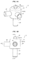
- FIGs. 1A and 1B are views showing a main structure of a first embodiment of a flow channel switching valve according to the present invention, in which Fig. 1A is a perspective view and Fig. 1 B is a side elevational view. Further, Fig. 2 is a cross-sectional view as seen from an arrow A-A in Fig. 1 B , and Fig. 3 is a cross-sectional view as seen from an arrow B-B in Fig. 1 B . Fig. 3 shows a state in which a valve element is rotated at about 45 degrees in a counterclockwise direction as seen from the below in relation to Figs. 1 and 2 . Further, in Figs. 1 to 3 , a rotation drive unit constructed by a motor for rotating the valve element is omitted.
- a flow channel switching valve 1 is used, for example, as a three-way switching valve which switches a flow channel for a fluid flowing in an engine room of a motor vehicle to multiple directions, and is basically provided with a valve body 10 which has a valve chamber 11 and is made of a resin, a motor (a rotation drive unit) (not shown) which is arranged above the valve body 10, a seal member 30 which is arranged within the valve chamber 11 of the valve body 10 and serves as a valve seat, and a valve element 20 which is constructed by a valve shaft 21 coupled to an output shaft of the motor and a cylindrical valve element portion 22 accommodated in a region surrounded by the seal member 30 with a ceiling portion and is made of a resin.
- the valve body 10 is constructed by a cylindrical base body 12 and a lower port member 15, and with cylindrical base body 12 there are formed two outflow ports 11 a and 11 b in its outer peripheral portion which are open to the valve chamber 11 at a predetermined angular interval (an angular interval of 90 degrees in the illustrated example) as well as being formed a valve chamber 11 in its inner portion, and has a cylindrical barrel portion 13 with a ceiling portion 13a.
- Outflow ports p1 and p2 constructed by joints are integrally formed in the cylindrical barrel portion 13 so as to be communicated with the respective outflow ports 11 a and 11 b.
- a fitting insertion hole 14 to which the valve shaft 21 of the valve element 20 is inserted is formed in the ceiling portion 13a.
- a lower port member 15 having an inflow port p3 constructed by a joint is inward fitted and fixed to a lower opening of the cylindrical barrel portion 13 (the cylindrical base body 12) according to ultrasonic welding, press fitting or caulking. As a result, a vertical inlet opening 11c open to the valve chamber 11 is formed.
- the valve element 20 is structured, as can be well understood by referring to Fig. 4 together with Figs. 1 to 3 , such that two oval communication ports 22a and 22b are formed at a predetermined angular interval (an angular interval of 90 degrees in the illustrated example) in a peripheral direction, and an upper opening is occluded by the ceiling portion of cylindrical valve element portion 23, and has a cylindrical valve element portion 22 which is arranged rotatably within the valve chamber 11 (in other words, the cylindrical barrel portion 13), and a valve shaft 21 which is provided on the ceiling portion 23 of the cylindrical valve element portion in a protruding manner.
- Bridging portions 19a and 19b extending in a peripheral direction (a rotating direction) are integrally formed at the upper and lower center of each of the communication ports 22a and 22b formed in the cylindrical valve element portion 22 of the valve element 20 so as to be along an outer periphery of the cylindrical valve element portion 22. Further, the periphery of an outer peripheral side of each of the communication ports 22a and 22b is formed to be rounded (with rounded portions 18a and 18b).
- valve shaft 21 is constructed by an intermediate shaft portion 21 a which is rotatably fitted and inserted to the fitting insertion hole 14 and has a smaller diameter than that of the cylindrical valve element portion 22, and an upper shaft portion 21 b which is provided on the intermediate shaft portion 21 a in a protruding manner, is coupled to an output shaft of the motor and is formed into an oval shape in a plan view, and O-rings 24 serving as a seal member are interposed in two stages between the intermediate shaft portion 21 a and an inner peripheral surface of the fitting insertion hole 14.
- annular seat member 23a made of PTFE for slipping is interposed between (an upper surface of) the ceiling portion 23 of the cylindrical valve element portion and (a lower surface of) the ceiling portion 13a of the cylindrical barrel portion 13 (in other words, an outer periphery of the valve shaft 21 in the upper surface of the ceiling portion 23 of the cylindrical valve element portion) so as to reduce a sliding resistance of the ceiling portion 23 of the cylindrical valve element portion against the valve body 10 at the flow channel switching time (the valve element 20 rotating time).
- the seal member 30 is made of an elastic raw material such as a rubber so as to be symmetrical vertically, and is basically constructed by a cylindrical body 31 in which four oval openings 31 a to 31 d are formed at predetermined angular intervals (angular intervals of 90 degrees in the illustrated example) in a peripheral direction, and inside ribs 32a to 32d and outside ribs 33a to 33d for sealing which are provided around the respective openings 31a to 31 d of the cylindrical body 31 so as to protrude inward and outward.
- the cylindrical seal member 30 is interposed in a compressed state between the cylindrical barrel portion 13 of the valve body 10 and the cylindrical valve element portion 22 of the valve element 20 along the outer periphery of the valve chamber 11 so as to suppress leakage of the fluid between the valve chamber 11 and each of the outflow ports 11 a and 11 b, in detail, in such a manner that an upper end portion (of the cylindrical body 31) comes into contact with the ceiling portion 13a of the cylindrical barrel portion 13 in the valve body 10, a lower end portion (of the cylindrical body) 31 comes into contact with the lower port member 15 of the valve body 10, (inner peripheral sides of) the inside ribs 32a to 32d come into contact with the cylindrical valve element portion 22 of the valve element 20, and (outer peripheral sides of) the outside ribs 33a to 33d come into contact with an outer peripheral portion of the cylindrical barrel portion 13 in the valve body 10.
- the seal member 30 When the flow channel switching valve 1 mentioned above is assembled, the seal member 30 is inserted into the cylindrical barrel portion 13 of the cylindrical base body 12 in such a manner as to press fit while positioning the seal member 30 in relation to the valve body 10 so that the adjoining openings 31a and 31b are always communicated among the respective openings 31a to 31 d formed in (the cylindrical body 31 of) the seal member 30 with the respective outflow ports 11 a and 11 b formed in (the cylindrical barrel portion 13 of) the valve body 10 from the below before the lower port member 15 is inward fitted and fixed to the cylindrical barrel portion 13 of the cylindrical base body 12.
- the annular seat member 23a is arranged on an upper surface of the ceiling portion 23 of the cylindrical valve element portion from a lower side thereof, and the valve element 20 in which the O-rings 24 are installed to the intermediate shaft portion 21 a is inserted in such a manner as to be press fitted.
- the seat member 23a comes into contact with the ceiling portion 13a of the cylindrical barrel portion 13, and is inward inserted to an inner peripheral side of (the inside ribs 32a to 32d of) the seal member 30 slidably and rotatably while compressing the seal member 30 to such a degree that can secure a compression margin necessary for the seal with the seal member 30 in a state in which the cylindrical valve element portion 22 of the valve element 20 is supported from the periphery by the inside ribs 32a to 32d.
- the lower port member 15 is inward fitted and fixed to the lower opening of the cylindrical barrel portion 13 in the cylindrical base body 12, and the motor is installed to the above of the cylindrical base body 12.
- the cylindrical valve element portion 22 of the valve element 20 is structured such as to rotate and slide along the inner peripheral side (of the inside ribs 32a to 32d) of the seal member 30 by rotating the valve element 20 by driving the motor, thereby opening and closing or switching the outflow ports 11a and 11b of the valve body 10.
- the following four open and close modes can be selectively adopted as well as the inlet opening 11c formed in the valve body 10 always communicates with the valve chamber 11 (via the lower opening of the cylindrical valve element portion 22 in the valve element 20).
- the four open and close modes includes an open-open mode that the respective outflow ports 11a and 11 b formed in the valve body 10 communicate with the valve chamber 11 (via the respective openings 31 a and 31b of the seal member 30 and the respective communication ports 22a and 22b of the cylindrical valve element portion 22 in the valve element 20), a close-close mode that the outflow ports 11a and 11 b are closed (by the cylindrical valve element portion 22 of the valve element 20), an open-close mode that the outflow port 11 a communicates with the valve chamber 11 (via the opening 31 a of the seal member 30 and the communication port 22b of the cylindrical valve element portion 22 in the valve element 20) and the outflow port 11 b is closed (by the cylindrical valve element portion 22 of the valve element 20), and a close-open mode that the outflow port 11 a is closed (by the cylindrical valve element portion 22 of the valve element 20) and the outflow port 11 b communicates with the valve chamber 11 (via the opening 31 b of the seal member 30 and the communication port 22a of the cylindrical valve element portion
- the valve element 20 when the flow channel is switched as mentioned above by rotating the valve element 20 on the basis of the motor driving, the valve element 20 is rotated in a state in which the cylindrical valve element portion 22 slides with the inner peripheral sides of the inside ribs 32a to 32d of the seal member 30, and the inside ribs 32a to 32d of the seal member 30 pass through the communication ports 22a and 22b formed in the cylindrical valve element portion 22 in the middle of the flow channel switching.
- the respective communication ports 22a and 22b are provided with bridging portions 19a and 19b which extend in a peripheral direction (a rotating direction) so as to be along the outer periphery of the cylindrical valve element portion 22.
- a peripheral direction a rotating direction
- the bridging portions 19a and 19b are comparatively hard, it is possible to prevent the inside ribs 32a to 32d of the seal member 30 from getting down (falling away) into the respective communication ports 22a and 22b, as shown in Fig. 5A .
- the bridging portions 19a and 19b are comparatively soft, the bridging portions 19a and 19b bend and the inside ribs 32a to 32d of the seal member 30 may get down into the respective communication ports 22a and 22b.
- the inside ribs 32a to 32d are guided to the bridging portions 19a and 19b and can assist the inside ribs 32a to 32d running on the respective communication ports 22a and 22b, and it is possible to effectively reduce the torque required for switching the flow channel.
- the bridging portions 19a and 19b have a curved shape which connects both end portions in the peripheral direction of the respective communication ports 22a and 22b, however, the bridging portions 19a and 19b my have a linear shape which connects both end portions in the peripheral direction of the respective ports 22a and 22b.
- the bridging portions 19a and 19b are provided respectively only one in the vertically center of the respective communication ports 22a and 22b (particularly in the respective cover side communication ports 27a and 27b) as well as having the same thickness (a thickness in a diametrical direction) as the cylindrical valve element portion 22.
- the position, the number and the cross-sectional shape of the bridging portions provided in the communication ports 22a and 22b may be appropriately designed.
- Fig. 6 is a vertical cross-sectional view showing a main structure of a second embodiment of the flow channel switching valve according to the present invention and is a view along the arrow A-A in Fig. 1 B
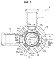
- Fig. 7 is a transverse cross-sectional view showing the main structure of the second embodiment of the flow channel switching valve according to the present invention and is a view along the arrow A-A in Fig. 1 B
- Figs. 8A and 8B are perspective views showing a valve element in Fig. 6 , in which Fig. 8A is a view showing an assembly completed state and Fig. 8B is a view showing an assembly midstream state, and Fig. 9 is a perspective view showing a cylindrical cover portion in Fig. 8 .
- a flow channel switching valve 2 according to the present embodiment is different from the flow channel switching valve 1 according to the first embodiment mentioned above in a point that a cylindrical valve element portion of a valve element is constructed by two members including a cylindrical main body portion and a cylindrical cover portion, and is formed by putting the cylindrical cover portion on the cylindrical main body portion, and is the same as the flow channel switching valve 1 according to the first embodiment in the other structures. Therefore, the same reference numerals are attached to the same structures as those of the first embodiment, and a detailed description thereof will be omitted.
- the cylindrical valve element portion 22 in the valve element 40 is constructed by a cylindrical main body portion 25 with a ceiling portion which is made of a raw material having a comparatively high mechanical strength such as polyphenylene sulfide (PPS) resin, and a cylindrical cover portion 27 which covers an outer side of the cylindrical body portion 25 (a portion around the valve shaft 21 in an outer periphery of the cylindrical main body portion 25 and an upper surface of the ceiling portion of cylindrical main body portion 26), is made of a raw material having a lower sliding resistance against the seal member 30 and the valve body 10 than the cylindrical main body portion 25 such as PTFE (also called as Teflon (trademark)) or a polyacetal (POM) resin, and main body side communication ports 25a and 25b and cover side communication ports 27a and 27b are formed respectively in the cylindrical
- PTFE also called as Teflon (trademark)
- POM polyacetal
- the main body side communication ports 25a and 25b and the cover side communication ports 27a and 27b construct the communication ports 22a and 22b and have the same shape.
- an engagement mechanism 29 is provided between the outer periphery of the cylindrical main body portion 25 and the inner periphery of the cylindrical cover portion 27, the engagement mechanism being constructed by a serration fitting structure integrally engaging the cylindrical main body portion 25 and the cylindrical cover portion 27.
- valve shaft 21 is provided so as to protrude upward from the center of the ceiling portion 26 of the cylindrical main body portion, bridging portions 19a and 19b extending in a peripheral direction (a rotating direction) are integrally formed at vertically the centers of the respective cover side communication ports 27a and 27b formed in the cylindrical cover portion 27 so as to be along an outer periphery of the cylindrical valve element portion 22 (that is, an outer periphery of the cylindrical cover portion 27), and peripheries in outer peripheral sides of the respective cover side communication ports 27a and 27b are formed to be rounded (rounded portions 18a and 18b).
- the engagement mechanism 29 integrally engaging the cylindrical main body portion 25 and the cylindrical cover portion 27 employs the serration fitting structure constructed by an external gear which is formed in the outer periphery of the cylindrical main body portion 25 and an internal gear which is formed in the inner periphery of the cylindrical cover portion 27.
- the cylindrical main body portion 25 and the cylindrical cover portion 27 may be engaged by concavities and convexities (refer to Fig. 10 ), chamfer portions or D-cut surfaces (refer to Fig. 11 ) formed between the outer periphery of the cylindrical main body 25 and the inner periphery of the cylindrical cover portion 27.
- the cylindrical main body portion 25 and the cylindrical cover portion 27 may be integrated by welding, adhesive bonding, caulking or fastening.
- the ceiling portion 28 of the cylindrical cover portion 27 in the cylindrical valve element portion 22 comes into contact with the ceiling portion 13a of the cylindrical barrel portion 13
- the valve element 40 is arranged within the valve chamber 11 in a posture that (the outer peripheral side of) the cylindrical cover portion 27 of the cylindrical valve element portion 22 comes into contact with (the inner peripheral side of) the inside ribs 32a to 32b, and the four open and close modes mentioned above are selectively adopted by rotating the valve element 40 on the basis of the motor driving so as to switch the flow channel as mentioned above, in the same manner as the flow channel switching valve 1 according to the first embodiment.
- the inner peripheral side of (the inside ribs 30a to 30d of) the seal member 30 and the cylindrical cover portion 27 (the outer side in the cylindrical valve element portion 22 of the valve element 20) sliding along (the ceiling portion 13a of the cylindrical barrel portion 13 of) the valve body 10 when the flow channel is switched are formed by the raw material having the lower sliding resistance against the seal member 30 and the valve body 10 than the cylindrical main body portion 25 (the inner side in the cylindrical valve element portion 22 of the valve element 20).
- the bridging portions 19a and 19b are provided only in the cover side communication ports 27a and 27b in the outer side among the main body side communication ports 25a and 25b and the cover side communication ports 27a and 27b constructing the respective communication ports 22a and 22b, however, it goes without saying that the same bridging portions as the bridging portions 19a and 19b may be provided in the main body side communication ports 25a and 25b. In this case, even if (the bridging portions 19a and 19b of) the cylindrical cover portion 27 are soft, it is possible to securely prevent the inside ribs 32a to 32d of the seal member 30 from getting down into the respective communication ports 22a and 22b.
- the embodiment mentioned above employs the aspect that the cylindrical valve element 22 of the valve element 40 is formed by two members including the cylindrical main body portion 25 and the cylindrical cover portion 27.
- the cylindrical main body portion 25 and the cylindrical cover portion 27 may be integrally formed, for example, a two-color molding (a double injection molding), and the outer side in the cylindrical valve element portion 22 of the valve element 40 may be formed by the raw material having the lower sliding resistance against the seal member 30 than that in the inner side thereof.
- the valve element 40 is made of the resin, however, may be of course made of, for example, a metal.
- the cylindrical main body portion 25 and the cylindrical cover portion 27 constructing the valve element 40 are made of the different raw materials.
- the cylindrical main body portion 25 and the cylindrical cover portion 27 may be made of the same raw material, and a surface treatment for reducing the sliding resistance against (the inside ribs 32a to 32d of) the seal member 30 and (the ceiling portion 13a of the cylindrical barrel portion 13 of) the valve body 10 may be applied to an outer peripheral surface or an upper surface of the cylindrical cover portion 27.
Landscapes
- Engineering & Computer Science (AREA)
- General Engineering & Computer Science (AREA)
- Mechanical Engineering (AREA)
- Multiple-Way Valves (AREA)
- Taps Or Cocks (AREA)
Abstract
Description
- The present invention is involved with a flow channel switching valve, and relates to a rotary type flow channel switching valve which switches a flow channel by rotationally sliding a valve element in an inner side of a seal member, for example, serving as a valve seat which suppresses leakage of a fluid between a valve chamber and each of outflow ports.
- This kind of conventional example will be shown in
Fig. 12 . A flow channel switching valve 1' according to the illustrated conventional example is used, for example, as a rotary type switching valve (a rotary valve) which switches a flow channel of a fluid flowing within an engine room of a motor vehicle, is provided with arotation drive unit 50, avalve body 10 having avalve chamber 11 andoutflow ports valve chamber 11, aseal member 30 which is arranged within thevalve chamber 11 of thevalve body 10, theseal member 30 having acylindrical body 31 in which a plurality ofopenings 31a to 31 d are formed in a peripheral direction, and insideribs 32a to 32d andoutside ribs 33a to 33d which are provided so as to protrude toward an inner side and an outer side from an inner peripheral surface and an outer peripheral surface of thecylindrical body 31 along peripheries of theopenings 31a to 31 d, and avalve element 20 constructed by avalve shaft 21 which is coupled to therotation drive unit 50 and avalve element portion 22 which is accommodated in a region surrounded by theseal member 30, and is structured such that thevalve element portion 22 rotationally slides around the inner peripheral sides of theinside ribs 32a to 32d of theseal member 30 so as to open and close or switch theoutflow ports valve body 10 by rotating thevalve element portion 22 within thevalve chamber 11 via thevalve shaft 21 by the rotation drive unit 50 (for example, patent document 1). - Patent Document 1:
Japanese Unexamined Patent Publication No. 2015-034560 - In the meanwhile, in the flow channel switching valve 1' of the above conventional example, (the inside rib of) the seal member passes through a communication port formed in the valve element portion of the valve element when the flow channel is switched by rotating the valve element, however, (the inside rib of) the seal member partly gets down (falls away) into the communication port due to its elasticity at the passing time, and a great torque is required for the (the inside rib of) the seal member getting down to run on the communication port. Therefore, there has been a problem that the rotation drive unit is enlarged in its size.
- The present invention is made by taking the problem mentioned above into consideration, and an object of the present invention is to provide a flow channel switching valve which can prevent a seal member from getting down into a communication port, or can effectively reduce a torque required for switching a flow channel by assisting the seal member running on the communication port, with a simple structure.
- In order to solve the problem mentioned above, a flow channel switching valve according to the present invention is provided with a valve body in which a valve chamber is formed in its inner portion and which has a cylindrical barrel portion provided with a plurality of outflow ports in its outer peripheral portion, a valve element in which a plurality of communication ports are formed in a peripheral direction and which has a cylindrical valve element portion occluded its upper opening and rotatably arranged within the valve chamber, a rotation drive unit for rotating the valve element, and a seal member which is interposed between the cylindrical barrel portion of the valve body and the cylindrical valve element portion of the valve element so as to suppress leakage of a fluid between the valve chamber and each of the outflow ports, and is structured such that the cylindrical valve element portion rotationally slides around an inner peripheral side of the seal member so as to open and close or switch the outflow port of the valve body, by rotating the cylindrical valve element portion of the valve element within the valve chamber by the rotation drive unit, wherein a bridging portion connecting both end portions in the peripheral direction of the communication port is provided in each of the communication ports in the cylindrical valve element portion of the valve element.
- According to a preferable aspect, an outer side in the cylindrical valve element portion of the valve element is formed by a raw material having a lower sliding resistance against the seal member in comparison with an inner side.
- Further, a flow channel switching valve according to the present invention is provided with a valve body in which a valve chamber is formed in its inner portion and which has a cylindrical barrel portion provided with a plurality of outflow ports in its outer peripheral portion, a valve element in which a plurality of communication ports are formed in a peripheral direction and which has a cylindrical valve element portion occluded its upper opening and rotatably arranged within the valve chamber, a rotation drive unit for rotating the valve element, and a seal member which is interposed between the cylindrical barrel portion of the valve body and the cylindrical valve element portion of the valve element so as to suppress leakage of a fluid between the valve chamber and each of the outflow ports, and is structured such that the cylindrical valve element portion rotationally slides around an inner peripheral side of the seal member so as to open and close or switch the outflow port of the valve body, by rotating the cylindrical valve element portion of the valve element within the valve chamber by the rotation drive unit, wherein the cylindrical valve element portion is formed by an outer side of a cylindrical main body portion being coated with a cylindrical cover portion made of a raw material having a lower sliding resistance against the seal member in comparison with the cylindrical main body portion, and a bridging portion connecting both end portions in a peripheral direction of the communication port is provided in each of the communication ports in the cylindrical cover portion of the cylindrical valve element portion.
- In a preferable aspect, an engagement mechanism integrally engaging the cylindrical main body portion with the cylindrical cover portion is provided between an outer periphery of the cylindrical main body portion and an inner periphery of the cylindrical cover portion.
- In a further preferable aspect, a bridging portion connecting both end portions in the peripheral direction of the communication port is provided in each of the communication ports in the cylindrical main body portion of the cylindrical valve element portion.
- In the other preferable aspect, the bridging portion is provided along an outer periphery of the cylindrical valve element portion or the cylindrical cover portion.
- In a further preferable aspect, the bridging portion is provided at the upper and lower center portion of each of the communication ports.
- In the other preferable aspect, a periphery of an outer peripheral side of each of the communication ports is formed to be rounded.
- According to the present invention, the bridging portion connecting both the end portions in the peripheral direction of the communication port is provided in each of the communication ports in the cylindrical valve element portion of the valve element which rotationally slides around the inner peripheral side of the seal member. As a result, it is possible to prevent the seal member from getting down into the communication port when the flow channel is switched by rotating the valve element, or it is possible to reduce the torque required for switching the flow channel by assisting the seal member running on the communication port.
- Further, the cylindrical valve element portion of the valve element is formed, for example, by the outer side of the cylindrical main body portion being coated with the cylindrical cover portion made of the raw material having the lower sliding resistance against the seal member in comparison with the cylindrical main body portion, and the outer side in the cylindrical valve element portion of the valve element is formed by the raw material having the lower sliding resistance against the seal member in comparison with the inner side thereof. As a result, it is possible to reduce the torque required for switching the flow channel by making the sliding resistance against the seal member smaller.
-
-
Figs. 1A and 1B are views showing a main structure of a first embodiment of a flow channel switching valve according to the present invention, in whichFig. 1A is a perspective view andFig. 1 B is a side elevational view; -
Fig. 2 is a cross-sectional view as seen from an arrow A-A inFig. 1 B; -
Fig. 3 is a cross-sectional view as seen from an arrow B-B inFig. 1 B; -
Fig. 4 is a perspective view showing a valve element inFig. 1 ; -
Fig. 5A is a cross-sectional view as seen from an arrow U-U inFig. 4 and is a view showing the valve element together with a seal member; -
Fig. 5B is a cross-sectional view as seen from an arrow V-V inFig. 4 and is a view showing the valve element together with the seal member; -
Fig. 6 is a vertical cross-sectional view showing a main structure of a second embodiment of the flow channel switching valve according to the present invention and is a view along the arrow A-A inFig. 1 B; -
Fig. 7 is a transverse cross-sectional view showing the main structure of the second embodiment of the flow channel switching valve according to the present invention and is a view along the arrow B-B inFig. 1 B; -
Figs. 8A and 8B are perspective views showing a valve element inFig. 6 , in whichFig. 8A is a view showing an assembly completed state andFig. 8B is a view showing an assembly midstream state; -
Fig. 9 is a perspective view showing a cylindrical cover portion inFig. 8 ; -
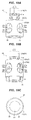
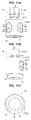
Figs. 10A, 10B and 10C are views showing the other example of the valve element shown inFig. 8 , in whichFig. 10A is a perspective view showing an assembly completed state,Fig. 10B is a perspective view showing an assembly midstream state, andFig. 10C is a bottom elevational view; -
Figs. 11 A, 11B and 11C are views showing further the other example of the valve element shown inFig. 8 , in whichFig. 11A is a perspective view showing an assembly completed state,Fig. 11B is a perspective view showing an assembly midstream state, andFig. 11C is a bottom elevational view; and -
Figs. 12A and 12B are views showing a conventional flow channel switching valve, in whichFig. 12A is a vertical cross-sectional view, andFig. 12B is a cross-sectional view as seen from an arrow X-X. - A description will be given below of embodiments according to the present invention with reference to the accompanying drawings.
-
Figs. 1A and 1B are views showing a main structure of a first embodiment of a flow channel switching valve according to the present invention, in whichFig. 1A is a perspective view andFig. 1 B is a side elevational view. Further,Fig. 2 is a cross-sectional view as seen from an arrow A-A inFig. 1 B , andFig. 3 is a cross-sectional view as seen from an arrow B-B inFig. 1 B .Fig. 3 shows a state in which a valve element is rotated at about 45 degrees in a counterclockwise direction as seen from the below in relation toFigs. 1 and2 . Further, inFigs. 1 to 3 , a rotation drive unit constructed by a motor for rotating the valve element is omitted. - A flow
channel switching valve 1 according to the illustrated embodiment is used, for example, as a three-way switching valve which switches a flow channel for a fluid flowing in an engine room of a motor vehicle to multiple directions, and is basically provided with avalve body 10 which has avalve chamber 11 and is made of a resin, a motor (a rotation drive unit) (not shown) which is arranged above thevalve body 10, aseal member 30 which is arranged within thevalve chamber 11 of thevalve body 10 and serves as a valve seat, and avalve element 20 which is constructed by avalve shaft 21 coupled to an output shaft of the motor and a cylindricalvalve element portion 22 accommodated in a region surrounded by theseal member 30 with a ceiling portion and is made of a resin. - The
valve body 10 is constructed by acylindrical base body 12 and alower port member 15, and withcylindrical base body 12 there are formed twooutflow ports valve chamber 11 at a predetermined angular interval (an angular interval of 90 degrees in the illustrated example) as well as being formed avalve chamber 11 in its inner portion, and has acylindrical barrel portion 13 with aceiling portion 13a. Outflow ports p1 and p2 constructed by joints are integrally formed in thecylindrical barrel portion 13 so as to be communicated with therespective outflow ports fitting insertion hole 14 to which thevalve shaft 21 of thevalve element 20 is inserted is formed in theceiling portion 13a. Alower port member 15 having an inflow port p3 constructed by a joint is inward fitted and fixed to a lower opening of the cylindrical barrel portion 13 (the cylindrical base body 12) according to ultrasonic welding, press fitting or caulking. As a result, avertical inlet opening 11c open to thevalve chamber 11 is formed. - The
valve element 20 is structured, as can be well understood by referring toFig. 4 together withFigs. 1 to 3 , such that twooval communication ports valve element portion 23, and has a cylindricalvalve element portion 22 which is arranged rotatably within the valve chamber 11 (in other words, the cylindrical barrel portion 13), and avalve shaft 21 which is provided on theceiling portion 23 of the cylindrical valve element portion in a protruding manner. - Bridging
portions communication ports valve element portion 22 of thevalve element 20 so as to be along an outer periphery of the cylindricalvalve element portion 22. Further, the periphery of an outer peripheral side of each of thecommunication ports rounded portions - On the other hand, the
valve shaft 21 is constructed by anintermediate shaft portion 21 a which is rotatably fitted and inserted to thefitting insertion hole 14 and has a smaller diameter than that of the cylindricalvalve element portion 22, and anupper shaft portion 21 b which is provided on theintermediate shaft portion 21 a in a protruding manner, is coupled to an output shaft of the motor and is formed into an oval shape in a plan view, and O-rings 24 serving as a seal member are interposed in two stages between theintermediate shaft portion 21 a and an inner peripheral surface of thefitting insertion hole 14. - Further, in the illustrated example, an
annular seat member 23a made of PTFE for slipping is interposed between (an upper surface of) theceiling portion 23 of the cylindrical valve element portion and (a lower surface of) theceiling portion 13a of the cylindrical barrel portion 13 (in other words, an outer periphery of thevalve shaft 21 in the upper surface of theceiling portion 23 of the cylindrical valve element portion) so as to reduce a sliding resistance of theceiling portion 23 of the cylindrical valve element portion against thevalve body 10 at the flow channel switching time (thevalve element 20 rotating time). - Further, the
seal member 30 is made of an elastic raw material such as a rubber so as to be symmetrical vertically, and is basically constructed by acylindrical body 31 in which fouroval openings 31 a to 31 d are formed at predetermined angular intervals (angular intervals of 90 degrees in the illustrated example) in a peripheral direction, and insideribs 32a to 32d and outsideribs 33a to 33d for sealing which are provided around therespective openings 31a to 31 d of thecylindrical body 31 so as to protrude inward and outward. Thecylindrical seal member 30 is interposed in a compressed state between thecylindrical barrel portion 13 of thevalve body 10 and the cylindricalvalve element portion 22 of thevalve element 20 along the outer periphery of thevalve chamber 11 so as to suppress leakage of the fluid between thevalve chamber 11 and each of theoutflow ports ceiling portion 13a of thecylindrical barrel portion 13 in thevalve body 10, a lower end portion (of the cylindrical body) 31 comes into contact with thelower port member 15 of thevalve body 10, (inner peripheral sides of) theinside ribs 32a to 32d come into contact with the cylindricalvalve element portion 22 of thevalve element 20, and (outer peripheral sides of) theoutside ribs 33a to 33d come into contact with an outer peripheral portion of thecylindrical barrel portion 13 in thevalve body 10. - When the flow
channel switching valve 1 mentioned above is assembled, theseal member 30 is inserted into thecylindrical barrel portion 13 of thecylindrical base body 12 in such a manner as to press fit while positioning theseal member 30 in relation to thevalve body 10 so that the adjoiningopenings respective openings 31a to 31 d formed in (thecylindrical body 31 of) theseal member 30 with therespective outflow ports cylindrical barrel portion 13 of) thevalve body 10 from the below before thelower port member 15 is inward fitted and fixed to thecylindrical barrel portion 13 of thecylindrical base body 12. Next, theannular seat member 23a is arranged on an upper surface of theceiling portion 23 of the cylindrical valve element portion from a lower side thereof, and thevalve element 20 in which the O-rings 24 are installed to theintermediate shaft portion 21 a is inserted in such a manner as to be press fitted. As a result, theseat member 23a comes into contact with theceiling portion 13a of thecylindrical barrel portion 13, and is inward inserted to an inner peripheral side of (theinside ribs 32a to 32d of) theseal member 30 slidably and rotatably while compressing theseal member 30 to such a degree that can secure a compression margin necessary for the seal with theseal member 30 in a state in which the cylindricalvalve element portion 22 of thevalve element 20 is supported from the periphery by theinside ribs 32a to 32d. Further, thelower port member 15 is inward fitted and fixed to the lower opening of thecylindrical barrel portion 13 in thecylindrical base body 12, and the motor is installed to the above of thecylindrical base body 12. - In the flow
channel switching valve 1 having the structure mentioned above, the cylindricalvalve element portion 22 of thevalve element 20 is structured such as to rotate and slide along the inner peripheral side (of theinside ribs 32a to 32d) of theseal member 30 by rotating thevalve element 20 by driving the motor, thereby opening and closing or switching theoutflow ports valve body 10. Specifically, the following four open and close modes can be selectively adopted as well as theinlet opening 11c formed in thevalve body 10 always communicates with the valve chamber 11 (via the lower opening of the cylindricalvalve element portion 22 in the valve element 20). The four open and close modes includes an open-open mode that therespective outflow ports valve body 10 communicate with the valve chamber 11 (via therespective openings seal member 30 and therespective communication ports valve element portion 22 in the valve element 20), a close-close mode that theoutflow ports valve element portion 22 of the valve element 20), an open-close mode that theoutflow port 11 a communicates with the valve chamber 11 (via theopening 31 a of theseal member 30 and thecommunication port 22b of the cylindricalvalve element portion 22 in the valve element 20) and theoutflow port 11 b is closed (by the cylindricalvalve element portion 22 of the valve element 20), and a close-open mode that theoutflow port 11 a is closed (by the cylindricalvalve element portion 22 of the valve element 20) and theoutflow port 11 b communicates with the valve chamber 11 (via theopening 31 b of theseal member 30 and thecommunication port 22a of the cylindricalvalve element portion 22 in the valve element 20). - In the flow
channel switching valve 1 according to the present embodiment, when the flow channel is switched as mentioned above by rotating thevalve element 20 on the basis of the motor driving, thevalve element 20 is rotated in a state in which the cylindricalvalve element portion 22 slides with the inner peripheral sides of theinside ribs 32a to 32d of theseal member 30, and theinside ribs 32a to 32d of theseal member 30 pass through thecommunication ports valve element portion 22 in the middle of the flow channel switching. - In the flow
channel switching valve 1 according to the present embodiment, therespective communication ports portions valve element portion 22. As a result, in the case that the bridgingportions inside ribs 32a to 32d of theseal member 30 from getting down (falling away) into therespective communication ports Fig. 5A . On the other hand, in the case that the bridgingportions portions inside ribs 32a to 32d of theseal member 30 may get down into therespective communication ports inside ribs 32a to 32d are guided to thebridging portions inside ribs 32a to 32d running on therespective communication ports - Further, at positions where the
bridging portions respective communication ports portions inside ribs 32a to 32d of theseal member 30 get down slightly into thecommunication ports channel switching valve 1 according to the present embodiment, the peripheries in the outer peripheral sides of thecommunication ports inside ribs 32a to 32d of theseal member 30 running on therespective communication ports rounded corners Fig. 5B , it is also possible to effectively reduce the torque required for switching the flow channel. - In the embodiment mentioned above, the bridging
portions respective communication ports portions respective ports portions respective communication ports side communication ports valve element portion 22. However, it goes without saying that the position, the number and the cross-sectional shape of the bridging portions provided in thecommunication ports -
Fig. 6 is a vertical cross-sectional view showing a main structure of a second embodiment of the flow channel switching valve according to the present invention and is a view along the arrow A-A inFig. 1 B , andFig. 7 is a transverse cross-sectional view showing the main structure of the second embodiment of the flow channel switching valve according to the present invention and is a view along the arrow A-A inFig. 1 B . Further,Figs. 8A and 8B are perspective views showing a valve element inFig. 6 , in whichFig. 8A is a view showing an assembly completed state andFig. 8B is a view showing an assembly midstream state, andFig. 9 is a perspective view showing a cylindrical cover portion inFig. 8 . - A flow
channel switching valve 2 according to the present embodiment is different from the flowchannel switching valve 1 according to the first embodiment mentioned above in a point that a cylindrical valve element portion of a valve element is constructed by two members including a cylindrical main body portion and a cylindrical cover portion, and is formed by putting the cylindrical cover portion on the cylindrical main body portion, and is the same as the flowchannel switching valve 1 according to the first embodiment in the other structures. Therefore, the same reference numerals are attached to the same structures as those of the first embodiment, and a detailed description thereof will be omitted. - Describing in detail, in the flow
channel switching valve 2 according to the present embodiment, theseat member 23a for slipping between the ceiling portion of the cylindricalvalve element portion 23 and theceiling portion 13a of thecylindrical barrel portion 13 is removed, the cylindricalvalve element portion 22 in thevalve element 40 is constructed by a cylindricalmain body portion 25 with a ceiling portion which is made of a raw material having a comparatively high mechanical strength such as polyphenylene sulfide (PPS) resin, and acylindrical cover portion 27 which covers an outer side of the cylindrical body portion 25 (a portion around thevalve shaft 21 in an outer periphery of the cylindricalmain body portion 25 and an upper surface of the ceiling portion of cylindrical main body portion 26), is made of a raw material having a lower sliding resistance against theseal member 30 and thevalve body 10 than the cylindricalmain body portion 25 such as PTFE (also called as Teflon (trademark)) or a polyacetal (POM) resin, and main bodyside communication ports side communication ports main body portion 25 and thecylindrical cover portion 27. The main bodyside communication ports side communication ports communication ports engagement mechanism 29 is provided between the outer periphery of the cylindricalmain body portion 25 and the inner periphery of thecylindrical cover portion 27, the engagement mechanism being constructed by a serration fitting structure integrally engaging the cylindricalmain body portion 25 and thecylindrical cover portion 27. As a result, rotational positions of the cylindricalmain body portion 25 and thecylindrical cover portion 27 are defined, and the cylindricalmain body portion 25 and thecylindrical cover portion 27 are integrally rotated. - Further, the
valve shaft 21 is provided so as to protrude upward from the center of theceiling portion 26 of the cylindrical main body portion, bridgingportions side communication ports cylindrical cover portion 27 so as to be along an outer periphery of the cylindrical valve element portion 22 (that is, an outer periphery of the cylindrical cover portion 27), and peripheries in outer peripheral sides of the respective coverside communication ports rounded portions - In the illustrated example, the
engagement mechanism 29 integrally engaging the cylindricalmain body portion 25 and thecylindrical cover portion 27 employs the serration fitting structure constructed by an external gear which is formed in the outer periphery of the cylindricalmain body portion 25 and an internal gear which is formed in the inner periphery of thecylindrical cover portion 27. However, for example, as shown inFigs. 10 and11 , the cylindricalmain body portion 25 and thecylindrical cover portion 27 may be engaged by concavities and convexities (refer toFig. 10 ), chamfer portions or D-cut surfaces (refer toFig. 11 ) formed between the outer periphery of the cylindricalmain body 25 and the inner periphery of thecylindrical cover portion 27. Further, it goes without saying that the cylindricalmain body portion 25 and thecylindrical cover portion 27 may be integrated by welding, adhesive bonding, caulking or fastening. - In the flow
channel switching valve 2 having thevalve element 40 according to the structure, theceiling portion 28 of thecylindrical cover portion 27 in the cylindricalvalve element portion 22 comes into contact with theceiling portion 13a of thecylindrical barrel portion 13, thevalve element 40 is arranged within thevalve chamber 11 in a posture that (the outer peripheral side of) thecylindrical cover portion 27 of the cylindricalvalve element portion 22 comes into contact with (the inner peripheral side of) theinside ribs 32a to 32b, and the four open and close modes mentioned above are selectively adopted by rotating thevalve element 40 on the basis of the motor driving so as to switch the flow channel as mentioned above, in the same manner as the flowchannel switching valve 1 according to the first embodiment. However, the inner peripheral side of (the inside ribs 30a to 30d of) theseal member 30 and the cylindrical cover portion 27 (the outer side in the cylindricalvalve element portion 22 of the valve element 20) sliding along (theceiling portion 13a of thecylindrical barrel portion 13 of) thevalve body 10 when the flow channel is switched are formed by the raw material having the lower sliding resistance against theseal member 30 and thevalve body 10 than the cylindrical main body portion 25 (the inner side in the cylindricalvalve element portion 22 of the valve element 20). As a result, in addition to the effect of the first embodiment mentioned above, it is possible to further effectively reduce the toque required for switching the flow channel by making the sliding resistance against theseal member 30 and thevalve body 10 smaller. - In the embodiment mentioned above, the bridging
portions side communication ports side communication ports side communication ports respective communication ports portions side communication ports portions cylindrical cover portion 27 are soft, it is possible to securely prevent theinside ribs 32a to 32d of theseal member 30 from getting down into therespective communication ports - Further, the embodiment mentioned above employs the aspect that the
cylindrical valve element 22 of thevalve element 40 is formed by two members including the cylindricalmain body portion 25 and thecylindrical cover portion 27. However, it goes without saying that the cylindricalmain body portion 25 and thecylindrical cover portion 27 may be integrally formed, for example, a two-color molding (a double injection molding), and the outer side in the cylindricalvalve element portion 22 of thevalve element 40 may be formed by the raw material having the lower sliding resistance against theseal member 30 than that in the inner side thereof. - Further, in the embodiment mentioned above, the
valve element 40 is made of the resin, however, may be of course made of, for example, a metal. Further, in the embodiment mentioned above, the cylindricalmain body portion 25 and thecylindrical cover portion 27 constructing thevalve element 40 are made of the different raw materials. However, for example, the cylindricalmain body portion 25 and thecylindrical cover portion 27 may be made of the same raw material, and a surface treatment for reducing the sliding resistance against (theinside ribs 32a to 32d of) theseal member 30 and (theceiling portion 13a of thecylindrical barrel portion 13 of) thevalve body 10 may be applied to an outer peripheral surface or an upper surface of thecylindrical cover portion 27.
Claims (8)
- A flow channel switching valve comprising:a valve body in which a valve chamber is formed in its inner portion and which has a cylindrical barrel portion provided with a plurality of outflow ports in its outer peripheral portion;a valve element in which a plurality of communication ports are formed in a peripheral direction and which has a cylindrical valve element portion occluded its upper opening and rotatably arranged within said valve chamber;a rotation drive unit for rotating said valve element;a seal member which is interposed between the cylindrical barrel portion of said valve body and the cylindrical valve element portion of said valve element so as to suppress leakage of a fluid between said valve chamber and each of the outflow ports; andthe flow channel switching valve being structured such that said cylindrical valve element portion rotationally slides around an inner peripheral side of said seal member so as to open and close or switch said outflow port of said valve body, by rotating said cylindrical valve element portion of said valve element within said valve chamber by said rotation drive unit,characterized in that a bridging portion connecting both end portions in the peripheral direction of said communication port is provided in each of the communication ports in said cylindrical valve element portion of said valve element.
- The flow channel switching valve according to claim 1, characterized in that an outer side in said cylindrical valve element portion of said valve element is formed by a raw material having a lower sliding resistance against said seal member in comparison with an inner side.
- A flow channel switching valve comprising:a valve body in which a valve chamber is formed in its inner portion and which has a cylindrical barrel portion including a plurality of outflow ports in its outer peripheral portion;a valve element in which a plurality of communication ports are formed in a peripheral direction and which has a cylindrical valve element portion occluded its upper opening and rotatably arranged within said valve chamber;a rotation drive unit for rotating said valve element;a seal member which is interposed between the cylindrical barrel portion of said valve body and the cylindrical valve element portion of said valve element so as to suppress leakage of a fluid between said valve chamber and each of the outflow ports; andthe flow channel switching valve being structured such that said cylindrical valve element portion rotationally slides around an inner peripheral side of said seal member so as to open and close or switch said outflow port of said valve body, by rotating said cylindrical valve element portion of said valve element within said valve chamber by said rotation drive unit,characterized in that said cylindrical valve element portion is formed by an outer side of a cylindrical main body portion being coated with a cylindrical cover portion made of a raw material having a lower sliding resistance against said seal member in comparison with said cylindrical main body portion, andthat a bridging portion connecting both end portions in a peripheral direction of said communication port is provided in each of the communication ports in said cylindrical cover portion of said cylindrical valve element portion.
- The flow channel switching valve according to claim 3, characterized in that an engagement mechanism integrally engaging said cylindrical main body portion with said cylindrical cover portion is provided between an outer periphery of said cylindrical main body portion and an inner periphery of said cylindrical cover portion.
- The flow channel switching valve according to claim 3 or 4, characterized in that a bridging portion connecting both end portions in the peripheral direction of said communication port is provided in each of the communication ports in said cylindrical main body portion of said cylindrical valve element portion.
- The flow channel switching valve according to any one of claims 1 to 5, characterized in that said bridging portion is provided along an outer periphery of said cylindrical valve element portion or said cylindrical cover portion.
- The flow channel switching valve according to any one of claims 1 to 6, characterized in that said bridging portion is provided at the upper and lower center portion of each of the communication ports.
- The flow channel switching valve according to any one of claims 1 to 7, characterized in that a periphery of an outer peripheral side of each of the communication ports is formed to be rounded.
Applications Claiming Priority (1)
| Application Number | Priority Date | Filing Date | Title |
|---|---|---|---|
| JP2015186789A JP6656860B2 (en) | 2015-09-24 | 2015-09-24 | Flow path switching valve |
Publications (2)
| Publication Number | Publication Date |
|---|---|
| EP3153748A1 true EP3153748A1 (en) | 2017-04-12 |
| EP3153748B1 EP3153748B1 (en) | 2018-08-29 |
Family
ID=56344979
Family Applications (1)
| Application Number | Title | Priority Date | Filing Date |
|---|---|---|---|
| EP16174934.6A Active EP3153748B1 (en) | 2015-09-24 | 2016-06-17 | Flow channel switching valve |
Country Status (2)
| Country | Link |
|---|---|
| EP (1) | EP3153748B1 (en) |
| JP (1) | JP6656860B2 (en) |
Cited By (2)
| Publication number | Priority date | Publication date | Assignee | Title |
|---|---|---|---|---|
| WO2020244932A1 (en) * | 2019-06-06 | 2020-12-10 | Robert Bosch Gmbh | Fluid valve assembly including valve body with seal retention features |
| WO2023169648A1 (en) * | 2022-03-07 | 2023-09-14 | Johnson Electric International AG | Multi-port valve with proportional flow function |
Families Citing this family (5)
| Publication number | Priority date | Publication date | Assignee | Title |
|---|---|---|---|---|
| TWI808147B (en) * | 2019-03-27 | 2023-07-11 | 金德創新技術股份有限公司 | Guidance control device for fluid transmission and its application system |
| US11698139B2 (en) * | 2019-03-27 | 2023-07-11 | CH Creative Co., Ltd. | Fluid transfer guiding/controlling device and application system thereof |
| CN115560094A (en) * | 2021-07-02 | 2023-01-03 | 浙江三花汽车零部件有限公司 | Electric valve and its assembly method |
| CN115560093A (en) * | 2021-07-02 | 2023-01-03 | 浙江三花汽车零部件有限公司 | Valve core and electrically operated valve |
| PT119547A (en) * | 2024-06-24 | 2025-12-24 | Plasmaq Maqu E Equipamentos Para Industria De Plasticos Lda | DEVICE FOR SELECTING PLASTIC PARTICLES FOR RECYCLING COMPRISING A SET OF RIBS AND A METHOD FOR ADJUSTING THE RIBS |
Citations (7)
| Publication number | Priority date | Publication date | Assignee | Title |
|---|---|---|---|---|
| CH667142A5 (en) * | 1984-09-07 | 1988-09-15 | Technova Ag | Valve for corrosive fluids - has plastics liner and incorporates sealed valve element |
| JPH09210226A (en) * | 1996-02-05 | 1997-08-12 | Kitz Corp | Opening/closing valve |
| JP2004011813A (en) * | 2002-06-07 | 2004-01-15 | Toto Ltd | Cylinder valve |
| JP2006275248A (en) * | 2005-03-30 | 2006-10-12 | Kvk Corp | Hydrant valve device |
| JP2015034560A (en) | 2013-08-07 | 2015-02-19 | 株式会社不二工機 | Seal member and channel selector valve using the same |
| WO2015091403A1 (en) * | 2013-12-19 | 2015-06-25 | Valeo Systemes Thermiques | Movable barrel for a fluid circuit valve |
| US20150184761A1 (en) * | 2012-08-10 | 2015-07-02 | Nippon Thermostat Co., Ltd. | Rotary valve seal member and rotary valve using same |
Family Cites Families (4)
| Publication number | Priority date | Publication date | Assignee | Title |
|---|---|---|---|---|
| JPS6435263U (en) * | 1987-08-27 | 1989-03-03 | ||
| JPH01176867A (en) * | 1987-12-29 | 1989-07-13 | Toto Ltd | Changeover valve |
| JP3152129B2 (en) * | 1995-10-26 | 2001-04-03 | 松下電器産業株式会社 | Valve device |
| JP2007016876A (en) * | 2005-07-07 | 2007-01-25 | Kvk Corp | Valve device |
-
2015
- 2015-09-24 JP JP2015186789A patent/JP6656860B2/en active Active
-
2016
- 2016-06-17 EP EP16174934.6A patent/EP3153748B1/en active Active
Patent Citations (7)
| Publication number | Priority date | Publication date | Assignee | Title |
|---|---|---|---|---|
| CH667142A5 (en) * | 1984-09-07 | 1988-09-15 | Technova Ag | Valve for corrosive fluids - has plastics liner and incorporates sealed valve element |
| JPH09210226A (en) * | 1996-02-05 | 1997-08-12 | Kitz Corp | Opening/closing valve |
| JP2004011813A (en) * | 2002-06-07 | 2004-01-15 | Toto Ltd | Cylinder valve |
| JP2006275248A (en) * | 2005-03-30 | 2006-10-12 | Kvk Corp | Hydrant valve device |
| US20150184761A1 (en) * | 2012-08-10 | 2015-07-02 | Nippon Thermostat Co., Ltd. | Rotary valve seal member and rotary valve using same |
| JP2015034560A (en) | 2013-08-07 | 2015-02-19 | 株式会社不二工機 | Seal member and channel selector valve using the same |
| WO2015091403A1 (en) * | 2013-12-19 | 2015-06-25 | Valeo Systemes Thermiques | Movable barrel for a fluid circuit valve |
Cited By (4)
| Publication number | Priority date | Publication date | Assignee | Title |
|---|---|---|---|---|
| WO2020244932A1 (en) * | 2019-06-06 | 2020-12-10 | Robert Bosch Gmbh | Fluid valve assembly including valve body with seal retention features |
| KR20220017991A (en) * | 2019-06-06 | 2022-02-14 | 로베르트 보쉬 게엠베하 | A fluid valve assembly including a valve body having a seal retaining feature |
| KR102895165B1 (en) | 2019-06-06 | 2025-12-04 | 로베르트 보쉬 게엠베하 | A fluid valve assembly comprising a valve body having a sealing retaining feature. |
| WO2023169648A1 (en) * | 2022-03-07 | 2023-09-14 | Johnson Electric International AG | Multi-port valve with proportional flow function |
Also Published As
| Publication number | Publication date |
|---|---|
| JP2017061963A (en) | 2017-03-30 |
| JP6656860B2 (en) | 2020-03-04 |
| EP3153748B1 (en) | 2018-08-29 |
Similar Documents
| Publication | Publication Date | Title |
|---|---|---|
| EP3153748B1 (en) | Flow channel switching valve | |
| JP6511427B2 (en) | Flow path switching valve | |
| JP6656846B2 (en) | Flow path switching valve and seal member | |
| KR101570494B1 (en) | Automotive valve apparatus | |
| JP6656859B2 (en) | Flow path switching valve | |
| JP2017223299A (en) | Flow passage changeover valve | |
| CN111828687A (en) | a control valve | |
| JP6634572B2 (en) | Butterfly valve | |
| JP2011094787A (en) | Rotary valve | |
| CN111828682A (en) | a control valve | |
| JP7137583B2 (en) | eccentric butterfly valve | |
| JP5881335B2 (en) | Flow path switching valve | |
| KR101864641B1 (en) | Valve device and the manufacturing method of the same | |
| KR101804764B1 (en) | Multidirection multivalve for automotive | |
| US20190136989A1 (en) | Flow path switching valve | |
| KR100478294B1 (en) | Seat of bidirectional butterfly valve having inside elastic member | |
| JP6639975B2 (en) | Flow path switching valve | |
| JP2020159441A (en) | Three-way valve | |
| JP2011089581A (en) | Butterfly valve | |
| JP6709409B2 (en) | Butterfly valve | |
| JP2020159440A (en) | Revolver switching valve | |
| JP6402313B2 (en) | Butterfly valve | |
| JP6782128B2 (en) | Ball valve | |
| KR20160046692A (en) | Apparatus for rotating door | |
| JP2012021595A (en) | Butterfly valve |
Legal Events
| Date | Code | Title | Description |
|---|---|---|---|
| PUAI | Public reference made under article 153(3) epc to a published international application that has entered the european phase |
Free format text: ORIGINAL CODE: 0009012 |
|
| STAA | Information on the status of an ep patent application or granted ep patent |
Free format text: STATUS: THE APPLICATION HAS BEEN PUBLISHED |
|
| AK | Designated contracting states |
Kind code of ref document: A1 Designated state(s): AL AT BE BG CH CY CZ DE DK EE ES FI FR GB GR HR HU IE IS IT LI LT LU LV MC MK MT NL NO PL PT RO RS SE SI SK SM TR |
|
| AX | Request for extension of the european patent |
Extension state: BA ME |
|
| STAA | Information on the status of an ep patent application or granted ep patent |
Free format text: STATUS: REQUEST FOR EXAMINATION WAS MADE |
|
| 17P | Request for examination filed |
Effective date: 20170918 |
|
| RBV | Designated contracting states (corrected) |
Designated state(s): AL AT BE BG CH CY CZ DE DK EE ES FI FR GB GR HR HU IE IS IT LI LT LU LV MC MK MT NL NO PL PT RO RS SE SI SK SM TR |
|
| STAA | Information on the status of an ep patent application or granted ep patent |
Free format text: STATUS: EXAMINATION IS IN PROGRESS |
|
| 17Q | First examination report despatched |
Effective date: 20171031 |
|
| GRAP | Despatch of communication of intention to grant a patent |
Free format text: ORIGINAL CODE: EPIDOSNIGR1 |
|
| STAA | Information on the status of an ep patent application or granted ep patent |
Free format text: STATUS: GRANT OF PATENT IS INTENDED |
|
| INTG | Intention to grant announced |
Effective date: 20180420 |
|
| GRAS | Grant fee paid |
Free format text: ORIGINAL CODE: EPIDOSNIGR3 |
|
| GRAA | (expected) grant |
Free format text: ORIGINAL CODE: 0009210 |
|
| STAA | Information on the status of an ep patent application or granted ep patent |
Free format text: STATUS: THE PATENT HAS BEEN GRANTED |
|
| AK | Designated contracting states |
Kind code of ref document: B1 Designated state(s): AL AT BE BG CH CY CZ DE DK EE ES FI FR GB GR HR HU IE IS IT LI LT LU LV MC MK MT NL NO PL PT RO RS SE SI SK SM TR |
|
| REG | Reference to a national code |
Ref country code: GB Ref legal event code: FG4D |
|
| REG | Reference to a national code |
Ref country code: CH Ref legal event code: EP |
|
| REG | Reference to a national code |
Ref country code: AT Ref legal event code: REF Ref document number: 1035513 Country of ref document: AT Kind code of ref document: T Effective date: 20180915 |
|
| REG | Reference to a national code |
Ref country code: IE Ref legal event code: FG4D |
|
| REG | Reference to a national code |
Ref country code: DE Ref legal event code: R096 Ref document number: 602016005104 Country of ref document: DE |
|
| REG | Reference to a national code |
Ref country code: NL Ref legal event code: MP Effective date: 20180829 |
|
| REG | Reference to a national code |
Ref country code: LT Ref legal event code: MG4D |
|
| PG25 | Lapsed in a contracting state [announced via postgrant information from national office to epo] |
Ref country code: IS Free format text: LAPSE BECAUSE OF FAILURE TO SUBMIT A TRANSLATION OF THE DESCRIPTION OR TO PAY THE FEE WITHIN THE PRESCRIBED TIME-LIMIT Effective date: 20181229 Ref country code: RS Free format text: LAPSE BECAUSE OF FAILURE TO SUBMIT A TRANSLATION OF THE DESCRIPTION OR TO PAY THE FEE WITHIN THE PRESCRIBED TIME-LIMIT Effective date: 20180829 Ref country code: FI Free format text: LAPSE BECAUSE OF FAILURE TO SUBMIT A TRANSLATION OF THE DESCRIPTION OR TO PAY THE FEE WITHIN THE PRESCRIBED TIME-LIMIT Effective date: 20180829 Ref country code: NO Free format text: LAPSE BECAUSE OF FAILURE TO SUBMIT A TRANSLATION OF THE DESCRIPTION OR TO PAY THE FEE WITHIN THE PRESCRIBED TIME-LIMIT Effective date: 20181129 Ref country code: BG Free format text: LAPSE BECAUSE OF FAILURE TO SUBMIT A TRANSLATION OF THE DESCRIPTION OR TO PAY THE FEE WITHIN THE PRESCRIBED TIME-LIMIT Effective date: 20181129 Ref country code: SE Free format text: LAPSE BECAUSE OF FAILURE TO SUBMIT A TRANSLATION OF THE DESCRIPTION OR TO PAY THE FEE WITHIN THE PRESCRIBED TIME-LIMIT Effective date: 20180829 Ref country code: NL Free format text: LAPSE BECAUSE OF FAILURE TO SUBMIT A TRANSLATION OF THE DESCRIPTION OR TO PAY THE FEE WITHIN THE PRESCRIBED TIME-LIMIT Effective date: 20180829 Ref country code: LT Free format text: LAPSE BECAUSE OF FAILURE TO SUBMIT A TRANSLATION OF THE DESCRIPTION OR TO PAY THE FEE WITHIN THE PRESCRIBED TIME-LIMIT Effective date: 20180829 Ref country code: GR Free format text: LAPSE BECAUSE OF FAILURE TO SUBMIT A TRANSLATION OF THE DESCRIPTION OR TO PAY THE FEE WITHIN THE PRESCRIBED TIME-LIMIT Effective date: 20181130 |
|
| REG | Reference to a national code |
Ref country code: AT Ref legal event code: MK05 Ref document number: 1035513 Country of ref document: AT Kind code of ref document: T Effective date: 20180829 |
|
| PG25 | Lapsed in a contracting state [announced via postgrant information from national office to epo] |
Ref country code: HR Free format text: LAPSE BECAUSE OF FAILURE TO SUBMIT A TRANSLATION OF THE DESCRIPTION OR TO PAY THE FEE WITHIN THE PRESCRIBED TIME-LIMIT Effective date: 20180829 Ref country code: LV Free format text: LAPSE BECAUSE OF FAILURE TO SUBMIT A TRANSLATION OF THE DESCRIPTION OR TO PAY THE FEE WITHIN THE PRESCRIBED TIME-LIMIT Effective date: 20180829 Ref country code: AL Free format text: LAPSE BECAUSE OF FAILURE TO SUBMIT A TRANSLATION OF THE DESCRIPTION OR TO PAY THE FEE WITHIN THE PRESCRIBED TIME-LIMIT Effective date: 20180829 |
|
| PG25 | Lapsed in a contracting state [announced via postgrant information from national office to epo] |
Ref country code: RO Free format text: LAPSE BECAUSE OF FAILURE TO SUBMIT A TRANSLATION OF THE DESCRIPTION OR TO PAY THE FEE WITHIN THE PRESCRIBED TIME-LIMIT Effective date: 20180829 Ref country code: CZ Free format text: LAPSE BECAUSE OF FAILURE TO SUBMIT A TRANSLATION OF THE DESCRIPTION OR TO PAY THE FEE WITHIN THE PRESCRIBED TIME-LIMIT Effective date: 20180829 Ref country code: PL Free format text: LAPSE BECAUSE OF FAILURE TO SUBMIT A TRANSLATION OF THE DESCRIPTION OR TO PAY THE FEE WITHIN THE PRESCRIBED TIME-LIMIT Effective date: 20180829 Ref country code: ES Free format text: LAPSE BECAUSE OF FAILURE TO SUBMIT A TRANSLATION OF THE DESCRIPTION OR TO PAY THE FEE WITHIN THE PRESCRIBED TIME-LIMIT Effective date: 20180829 Ref country code: EE Free format text: LAPSE BECAUSE OF FAILURE TO SUBMIT A TRANSLATION OF THE DESCRIPTION OR TO PAY THE FEE WITHIN THE PRESCRIBED TIME-LIMIT Effective date: 20180829 Ref country code: IT Free format text: LAPSE BECAUSE OF FAILURE TO SUBMIT A TRANSLATION OF THE DESCRIPTION OR TO PAY THE FEE WITHIN THE PRESCRIBED TIME-LIMIT Effective date: 20180829 Ref country code: AT Free format text: LAPSE BECAUSE OF FAILURE TO SUBMIT A TRANSLATION OF THE DESCRIPTION OR TO PAY THE FEE WITHIN THE PRESCRIBED TIME-LIMIT Effective date: 20180829 |
|
| PG25 | Lapsed in a contracting state [announced via postgrant information from national office to epo] |
Ref country code: SM Free format text: LAPSE BECAUSE OF FAILURE TO SUBMIT A TRANSLATION OF THE DESCRIPTION OR TO PAY THE FEE WITHIN THE PRESCRIBED TIME-LIMIT Effective date: 20180829 Ref country code: DK Free format text: LAPSE BECAUSE OF FAILURE TO SUBMIT A TRANSLATION OF THE DESCRIPTION OR TO PAY THE FEE WITHIN THE PRESCRIBED TIME-LIMIT Effective date: 20180829 Ref country code: SK Free format text: LAPSE BECAUSE OF FAILURE TO SUBMIT A TRANSLATION OF THE DESCRIPTION OR TO PAY THE FEE WITHIN THE PRESCRIBED TIME-LIMIT Effective date: 20180829 |
|
| REG | Reference to a national code |
Ref country code: DE Ref legal event code: R097 Ref document number: 602016005104 Country of ref document: DE |
|
| PLBE | No opposition filed within time limit |
Free format text: ORIGINAL CODE: 0009261 |
|
| STAA | Information on the status of an ep patent application or granted ep patent |
Free format text: STATUS: NO OPPOSITION FILED WITHIN TIME LIMIT |
|
| 26N | No opposition filed |
Effective date: 20190531 |
|
| PG25 | Lapsed in a contracting state [announced via postgrant information from national office to epo] |
Ref country code: SI Free format text: LAPSE BECAUSE OF FAILURE TO SUBMIT A TRANSLATION OF THE DESCRIPTION OR TO PAY THE FEE WITHIN THE PRESCRIBED TIME-LIMIT Effective date: 20180829 |
|
| PG25 | Lapsed in a contracting state [announced via postgrant information from national office to epo] |
Ref country code: MC Free format text: LAPSE BECAUSE OF FAILURE TO SUBMIT A TRANSLATION OF THE DESCRIPTION OR TO PAY THE FEE WITHIN THE PRESCRIBED TIME-LIMIT Effective date: 20180829 |
|
| REG | Reference to a national code |
Ref country code: CH Ref legal event code: PL |
|
| REG | Reference to a national code |
Ref country code: BE Ref legal event code: MM Effective date: 20190630 |
|
| PG25 | Lapsed in a contracting state [announced via postgrant information from national office to epo] |
Ref country code: TR Free format text: LAPSE BECAUSE OF FAILURE TO SUBMIT A TRANSLATION OF THE DESCRIPTION OR TO PAY THE FEE WITHIN THE PRESCRIBED TIME-LIMIT Effective date: 20180829 |
|
| PG25 | Lapsed in a contracting state [announced via postgrant information from national office to epo] |
Ref country code: IE Free format text: LAPSE BECAUSE OF NON-PAYMENT OF DUE FEES Effective date: 20190617 |
|
| PG25 | Lapsed in a contracting state [announced via postgrant information from national office to epo] |
Ref country code: BE Free format text: LAPSE BECAUSE OF NON-PAYMENT OF DUE FEES Effective date: 20190630 Ref country code: LI Free format text: LAPSE BECAUSE OF NON-PAYMENT OF DUE FEES Effective date: 20190630 Ref country code: LU Free format text: LAPSE BECAUSE OF NON-PAYMENT OF DUE FEES Effective date: 20190617 Ref country code: CH Free format text: LAPSE BECAUSE OF NON-PAYMENT OF DUE FEES Effective date: 20190630 |
|
| PG25 | Lapsed in a contracting state [announced via postgrant information from national office to epo] |
Ref country code: FR Free format text: LAPSE BECAUSE OF NON-PAYMENT OF DUE FEES Effective date: 20190630 Ref country code: PT Free format text: LAPSE BECAUSE OF FAILURE TO SUBMIT A TRANSLATION OF THE DESCRIPTION OR TO PAY THE FEE WITHIN THE PRESCRIBED TIME-LIMIT Effective date: 20181229 |
|
| GBPC | Gb: european patent ceased through non-payment of renewal fee |
Effective date: 20200617 |
|
| PG25 | Lapsed in a contracting state [announced via postgrant information from national office to epo] |
Ref country code: GB Free format text: LAPSE BECAUSE OF NON-PAYMENT OF DUE FEES Effective date: 20200617 |
|
| PG25 | Lapsed in a contracting state [announced via postgrant information from national office to epo] |
Ref country code: CY Free format text: LAPSE BECAUSE OF FAILURE TO SUBMIT A TRANSLATION OF THE DESCRIPTION OR TO PAY THE FEE WITHIN THE PRESCRIBED TIME-LIMIT Effective date: 20180829 |
|
| PG25 | Lapsed in a contracting state [announced via postgrant information from national office to epo] |
Ref country code: HU Free format text: LAPSE BECAUSE OF FAILURE TO SUBMIT A TRANSLATION OF THE DESCRIPTION OR TO PAY THE FEE WITHIN THE PRESCRIBED TIME-LIMIT; INVALID AB INITIO Effective date: 20160617 Ref country code: MT Free format text: LAPSE BECAUSE OF FAILURE TO SUBMIT A TRANSLATION OF THE DESCRIPTION OR TO PAY THE FEE WITHIN THE PRESCRIBED TIME-LIMIT Effective date: 20180829 |
|
| PG25 | Lapsed in a contracting state [announced via postgrant information from national office to epo] |
Ref country code: MK Free format text: LAPSE BECAUSE OF FAILURE TO SUBMIT A TRANSLATION OF THE DESCRIPTION OR TO PAY THE FEE WITHIN THE PRESCRIBED TIME-LIMIT Effective date: 20180829 |
|
| REG | Reference to a national code |
Ref country code: DE Ref legal event code: R082 Ref document number: 602016005104 Country of ref document: DE Representative=s name: SCHWEIGER, MARTIN, DIPL.-ING. UNIV., DE Ref country code: DE Ref legal event code: R082 Ref document number: 602016005104 Country of ref document: DE Representative=s name: WUNDERLICH & HEIM PATENTANWAELTE PARTNERSCHAFT, DE |
|
| REG | Reference to a national code |
Ref country code: DE Ref legal event code: R082 Ref document number: 602016005104 Country of ref document: DE Representative=s name: WUNDERLICH & HEIM PATENTANWAELTE PARTNERSCHAFT, DE |
|
| PGFP | Annual fee paid to national office [announced via postgrant information from national office to epo] |
Ref country code: DE Payment date: 20250429 Year of fee payment: 10 |