EP3153697A1 - Valve assembly arrangement for an injection valve and injection valve - Google Patents
Valve assembly arrangement for an injection valve and injection valve Download PDFInfo
- Publication number
- EP3153697A1 EP3153697A1 EP15189051.4A EP15189051A EP3153697A1 EP 3153697 A1 EP3153697 A1 EP 3153697A1 EP 15189051 A EP15189051 A EP 15189051A EP 3153697 A1 EP3153697 A1 EP 3153697A1
- Authority
- EP
- European Patent Office
- Prior art keywords
- valve assembly
- valve
- magnetic member
- magnetic
- needle
- Prior art date
- Legal status (The legal status is an assumption and is not a legal conclusion. Google has not performed a legal analysis and makes no representation as to the accuracy of the status listed.)
- Withdrawn
Links
Images




Classifications
-
- F—MECHANICAL ENGINEERING; LIGHTING; HEATING; WEAPONS; BLASTING
- F02—COMBUSTION ENGINES; HOT-GAS OR COMBUSTION-PRODUCT ENGINE PLANTS
- F02M—SUPPLYING COMBUSTION ENGINES IN GENERAL WITH COMBUSTIBLE MIXTURES OR CONSTITUENTS THEREOF
- F02M61/00—Fuel-injectors not provided for in groups F02M39/00 - F02M57/00 or F02M67/00
- F02M61/16—Details not provided for in, or of interest apart from, the apparatus of groups F02M61/02 - F02M61/14
- F02M61/20—Closing valves mechanically, e.g. arrangements of springs or weights or permanent magnets; Damping of valve lift
-
- F—MECHANICAL ENGINEERING; LIGHTING; HEATING; WEAPONS; BLASTING
- F02—COMBUSTION ENGINES; HOT-GAS OR COMBUSTION-PRODUCT ENGINE PLANTS
- F02M—SUPPLYING COMBUSTION ENGINES IN GENERAL WITH COMBUSTIBLE MIXTURES OR CONSTITUENTS THEREOF
- F02M51/00—Fuel-injection apparatus characterised by being operated electrically
- F02M51/06—Injectors peculiar thereto with means directly operating the valve needle
- F02M51/0603—Injectors peculiar thereto with means directly operating the valve needle using piezoelectric or magnetostrictive operating means
-
- F—MECHANICAL ENGINEERING; LIGHTING; HEATING; WEAPONS; BLASTING
- F02—COMBUSTION ENGINES; HOT-GAS OR COMBUSTION-PRODUCT ENGINE PLANTS
- F02M—SUPPLYING COMBUSTION ENGINES IN GENERAL WITH COMBUSTIBLE MIXTURES OR CONSTITUENTS THEREOF
- F02M51/00—Fuel-injection apparatus characterised by being operated electrically
- F02M51/06—Injectors peculiar thereto with means directly operating the valve needle
- F02M51/061—Injectors peculiar thereto with means directly operating the valve needle using electromagnetic operating means
- F02M51/0625—Injectors peculiar thereto with means directly operating the valve needle using electromagnetic operating means characterised by arrangement of mobile armatures
- F02M51/0664—Injectors peculiar thereto with means directly operating the valve needle using electromagnetic operating means characterised by arrangement of mobile armatures having a cylindrically or partly cylindrically shaped armature, e.g. entering the winding; having a plate-shaped or undulated armature entering the winding
- F02M51/0671—Injectors peculiar thereto with means directly operating the valve needle using electromagnetic operating means characterised by arrangement of mobile armatures having a cylindrically or partly cylindrically shaped armature, e.g. entering the winding; having a plate-shaped or undulated armature entering the winding the armature having an elongated valve body attached thereto
- F02M51/0682—Injectors peculiar thereto with means directly operating the valve needle using electromagnetic operating means characterised by arrangement of mobile armatures having a cylindrically or partly cylindrically shaped armature, e.g. entering the winding; having a plate-shaped or undulated armature entering the winding the armature having an elongated valve body attached thereto the body being hollow and its interior communicating with the fuel flow
-
- F—MECHANICAL ENGINEERING; LIGHTING; HEATING; WEAPONS; BLASTING
- F02—COMBUSTION ENGINES; HOT-GAS OR COMBUSTION-PRODUCT ENGINE PLANTS
- F02M—SUPPLYING COMBUSTION ENGINES IN GENERAL WITH COMBUSTIBLE MIXTURES OR CONSTITUENTS THEREOF
- F02M51/00—Fuel-injection apparatus characterised by being operated electrically
- F02M51/06—Injectors peculiar thereto with means directly operating the valve needle
- F02M51/061—Injectors peculiar thereto with means directly operating the valve needle using electromagnetic operating means
- F02M51/0625—Injectors peculiar thereto with means directly operating the valve needle using electromagnetic operating means characterised by arrangement of mobile armatures
- F02M51/0664—Injectors peculiar thereto with means directly operating the valve needle using electromagnetic operating means characterised by arrangement of mobile armatures having a cylindrically or partly cylindrically shaped armature, e.g. entering the winding; having a plate-shaped or undulated armature entering the winding
- F02M51/0685—Injectors peculiar thereto with means directly operating the valve needle using electromagnetic operating means characterised by arrangement of mobile armatures having a cylindrically or partly cylindrically shaped armature, e.g. entering the winding; having a plate-shaped or undulated armature entering the winding the armature and the valve being allowed to move relatively to each other or not being attached to each other
-
- F—MECHANICAL ENGINEERING; LIGHTING; HEATING; WEAPONS; BLASTING
- F02—COMBUSTION ENGINES; HOT-GAS OR COMBUSTION-PRODUCT ENGINE PLANTS
- F02M—SUPPLYING COMBUSTION ENGINES IN GENERAL WITH COMBUSTIBLE MIXTURES OR CONSTITUENTS THEREOF
- F02M61/00—Fuel-injectors not provided for in groups F02M39/00 - F02M57/00 or F02M67/00
- F02M61/04—Fuel-injectors not provided for in groups F02M39/00 - F02M57/00 or F02M67/00 having valves, e.g. having a plurality of valves in series
- F02M61/08—Fuel-injectors not provided for in groups F02M39/00 - F02M57/00 or F02M67/00 having valves, e.g. having a plurality of valves in series the valves opening in direction of fuel flow
-
- F—MECHANICAL ENGINEERING; LIGHTING; HEATING; WEAPONS; BLASTING
- F02—COMBUSTION ENGINES; HOT-GAS OR COMBUSTION-PRODUCT ENGINE PLANTS
- F02M—SUPPLYING COMBUSTION ENGINES IN GENERAL WITH COMBUSTIBLE MIXTURES OR CONSTITUENTS THEREOF
- F02M63/00—Other fuel-injection apparatus having pertinent characteristics not provided for in groups F02M39/00 - F02M57/00 or F02M67/00; Details, component parts, or accessories of fuel-injection apparatus, not provided for in, or of interest apart from, the apparatus of groups F02M39/00 - F02M61/00 or F02M67/00; Combination of fuel pump with other devices, e.g. lubricating oil pump
- F02M63/0003—Fuel-injection apparatus having a cyclically-operated valve for connecting a pressure source, e.g. constant pressure pump or accumulator, to an injection valve held closed mechanically, e.g. by springs, and automatically opened by fuel pressure
- F02M63/0007—Fuel-injection apparatus having a cyclically-operated valve for connecting a pressure source, e.g. constant pressure pump or accumulator, to an injection valve held closed mechanically, e.g. by springs, and automatically opened by fuel pressure using electrically actuated valves
-
- F—MECHANICAL ENGINEERING; LIGHTING; HEATING; WEAPONS; BLASTING
- F02—COMBUSTION ENGINES; HOT-GAS OR COMBUSTION-PRODUCT ENGINE PLANTS
- F02M—SUPPLYING COMBUSTION ENGINES IN GENERAL WITH COMBUSTIBLE MIXTURES OR CONSTITUENTS THEREOF
- F02M2200/00—Details of fuel-injection apparatus, not otherwise provided for
- F02M2200/20—Fuel-injection apparatus with permanent magnets
Definitions
- This invention relates to a valve assembly arrangement for an injection valve, the valve assembly arrangement having a central longitudinal axis and comprising a first valve assembly and a second valve assembly, wherein the second valve assembly is axially arranged adjacent to and coupled to the first valve assembly, wherein the valve assembly arrangement comprises a valve housing, wherein the second valve assembly comprises a valve housing section having an orifice at an axial end area of the valve housing, the second valve assembly comprises a cavity in its valve housing section and the second valve assembly comprises a valve needle being axially movable in said cavity between a closing position and other positions.
- the invention also relates to an injection valve comprising a valve assembly arrangement.
- Injection valves are in wide spread use, in particular for internal combustion engines where they may be arranged in order to dose a fluid into an intake manifold of the internal of the internal combustion engine or directly into a combustion chamber of a cylinder of an internal combustion engine. Injection valves are manufactured in various forms in order to satisfy the various needs for the various combustion engines. Injection valves may accommodate an actuator for actuating a needle of the injection valve, which way, for example, be an electromagnetic actuator or a piezoelectric actuator.
- respective injection valves may be adapted to dose fluids under very high pressures.
- valve assembly arrangements comprising a passive valve and active valve which is upstream to the passive one.
- the passive valve is used to release fuel or gas (i.e. fluid) without being directly controlled but following to actuation of the upstream valve.
- the upstream valve is an active valve, i.e. for example a valve enabling active control by an electromagnet or the like.
- the passive valve is placed to protect an upstream valve to be exposed to difficult environmental conditions. The opening of the passive valve occurs when the upstream valve releases pressurized fuel or gas which by means of the pressure energy opens the passive valve.
- Such a valve assembly arrangement is known from WO 2013/083626 A1 . It comprises a first active valve assembly including an actuator and a second passive valve assembly.
- the closing function of the passive valve assembly is performed by a pre-compressed spring which keeps the passive valve normally closed.
- an object of the invention to provide an improved valve assembly arrangement for an injection valve and to provide an injection valve comprising such improved valve assembly arrangement.
- an object of the invention is that by such improvement the known disadvantageous limitations are removed as far as possible.
- the present invention provides a generic valve assembly arrangement for an injection valve as mentioned at the beginning wherein the second valve assembly comprises a first magnetic member being fixed to the valve needle of the second valve assembly and wherein the second valve assembly comprises a second magnetic member being fixed to the valve housing section of the second valve assembly.
- the invention suggests that at least one of the first magnetic member and the second magnetic member includes a permanent magnet or consists of a permanent magnet.
- a closing force on the valve needle of the second valve assembly may be generated by the permanent magnet, in particular by attracting the first magnetic member towards the second magnetic member or vice versa.
- the closing force on the valve needle is solely effected by the permanent magnet.
- the second valve assembly is in particular operated without a spring acting on the valve needle of the second valve assembly for moving the valve needle to the closing position.
- the second valve assembly is of the outward opening type and the first magnetic member is disposed at a side of the second magnetic member wherein said side is facing the axial end area.
- the first magnetic member may be disposed at a space which is adjacent to the second magnetic member in an axial direction towards an axial end area of the valve assembly arrangement for dispensing the fluid.
- the second valve assembly may be of the inward opening type and the second magnetic member may be disposed at a side of the first magnetic member wherein said side is facing the axial end area.
- the invention solves the above mentioned problem by means of a closing force of the second valve assembly (i.e. of the passive valve) which is at the maximum value when the second valve assembly is closed. Compared thereto the closing force is reduced when the second valve assembly is in an open condition. This allows to keep the second valve assembly closed when it is not supplied by pressurized fuel or gas from the first valve assembly and it allows to let the second valve assembly open as long as possible before the closing function has to be performed.
- a closing force of the second valve assembly i.e. of the passive valve
- the closing spring is replaced in the passive valve assembly by a passive valve design closing mechanism including at least one permanent magnet.
- the at least one permanent magnet is installed with the function to attract the valve needle of the second valve assembly to its closing position.
- a permanent magnet for example can be placed on the moving part (in particular on the valve needle of the second valve assembly) or could be placed in a fixed position on the valve body or in particular on a section of a valve housing which belongs to the second valve assembly. In case enhanced performances are required it is possible to place two permanent magnets to support the closing function.
- the opening principle of the valve assembly arrangement is that the first valve assembly, which may be a standard injector, opens under control of an electronic signal and that the second, i.e. passive, valve assembly opens due to the pressure of the fluid which is passing through the opened first valve assembly (i.e. a pressure of gas fuel) when the force resulting from the pressure exceeds the magnetic closing force.
- the diagram shown by figure 4 of this application provides a force displacement comparison for exemplary chosen embodiments of valve assembly arrangements.
- the ordinate represents the closing force in Newton and the abscissa shows a distance reduction to contact in millimeters wherein the starting point at 2 mm corresponds to "0 lift", i.e. a closed passive valve.
- the graph sp 1 refers to a spring load of 5 N/mm (N) and the graph sp 2 refers to a spring load of 10/mm (N).
- the symbol at P 1 indicates that a higher force is needed to keep the passive valve open.
- Graph m 1 represents the closing force of an exemplary embodiment of an inventive second valve assembly comprising a single magnet (N).
- Graph m 2 represents the closing force of an exemplary embodiment of an inventive second valve assembly comprising a standard force double magnet (N).
- N standard force double magnet
- the diagram shows that the permanent magnet closing design allows having a lower closing force when the valve needle is open. This technical feature allows increasing the passive valve pressure operative range with stable performances.
- permanent-magnetic material refers to a magnetic material being permanently magnetized.
- permanent magnet could be used in the application instead of the wording permanent-magnetic material.
- the first magnetic member and the second magnetic member contact each other or are closely spaced when the valve needle of the second valve assembly is in its closing position, and that an increasing movement of the valve needle of the second valve assembly away from its closing position results in an increasing distance between the first magnetic member and the second magnetic member.
- the closing force has its maximum in the closing condition.
- the outward opening type means that the valve is opened when at the axial end area the tip of the valve needle moves in an outward direction, i.e. away from the valve housing.
- inward opening type means that the valve is open by a movement of the valve needle directed inwardly to the valve housing.
- the first magnetic member is a ring-like member being axially flipped on the valve needle of the second valve assembly.
- the second magnetic member is a ringlike member, i.e. in particular a ring-shaped member, wherein the valve needle of the second valve assembly in particular is extending in the hole of the second magnetic member in a manner axially movable relative to the second magnetic member.
- the first magnetic member comprises at least one axial throughout opening and/or that the second magnetic member comprises at least one axial throughout opening.
- the invention suggests that at least one of the first magnetic member and the second magnetic member includes permanent-magnetic material or consists of permanent magnetic material.
- the first magnetic member and/or the second magnetic member includes permanent-magnetic material or consists of permanent magnetic material.
- the first magnetic member includes permanent-magnetic material or consists of permanent-magnetic material and that the second magnetic member includes ferromagnetic material or consists of ferromagnetic material.
- said ferromagnetic material is not permanently magnetized itself and for example may have soft magnetic properties like for example steel.
- the second magnetic member includes permanent-magnetic material or consists of permanent-magnetic material and that the first magnetic member includes ferromagnetic material or consists of ferromagnetic material.
- said ferromagnetic material is not permanently magnetized itself and for example may have soft magnetic properties like for example steel.
- the first magnetic member includes permanent-magnetic material or consists of permanent-magnetic material and that the second magnetic member includes permanent-magnetic material or consists of permanent-magnetic material.
- valve housing comprises a step having a surface facing away from the axial end area and providing a stop for a stopper being connected to the valve needle of the second valve assembly.
- the stopper is the first magnetic member or a member connected to the valve needle of the second valve assembly at a side of the first magnetic member wherein said side is facing the axial end area of the valve housing. This enables a limitation of the movement of the valve needle in an outward direction.
- first magnetic member and the second magnetic member are positioned proximate to each other. This enables a strong magnetic force for closing the valve.
- the second valve assembly is coupled to the first valve assembly in such a fashion that the first valve assembly is operable to inject fluid into the second valve assembly for increasing a fluid pressure in the second valve assembly to open the second valve assembly to enable dispensing of fluid from the valve assembly arrangement.
- the first valve assembly may for example be a standard DI injector.
- the first valve assembly is of the inward opening type and comprises:
- the present invention also comprises an injection valve comprising a valve assembly arrangement wherein the valve assembly arrangement comprises one or more features explained above or in the following.
- FIG. 1 With reference to Figures 1 , 1a and 1b it is described by way of example a first embodiment of an injection valve 1 according to the invention comprising a first preferred embodiment of a valve assembly arrangement 2 according to the present invention.
- the valve assembly arrangement 2 extends along a central longitudinal axis L and comprises a first valve assembly 3 which is an active valve assembly and a second valve assembly 4 which is a passive valve assembly.
- the valve assemblies 3, 4 are axially arranged adjacent to each other and coupled to each other.
- the valve assembly arrangement 2 comprises a valve housing which in its entirety is designated by the reference number 5.
- the exemplary shown injection valve 1 is in particular suitable for dosing a fluid, in particular for dosing fuel, to an internal combustion engine and comprises the valve assembly arrangement 2.
- the first valve assembly 3 is of the inward opening type and the second valve assembly 4 is of the outward opening type.
- the first valve assembly 3 of the inward opening type is basically constructed like the active valve assembly known from WO 2013/083626 A1 and, as described in this earlier application, is also similar to the injection valve described in EP 2 378 106 A1 .
- the disclosure of WO 2013/083626 A1 regarding said valve assembly is herewith incorporated in the disclosure of the present application. Accordingly, hereinafter only those details of the first valve assembly 3 of the inward opening type are described, which directly act together with the second valve assembly 4 of the outward opening type during operation.
- the first valve assembly 3 which is active operable and which is of the inward opening type comprises a valve housing section 6, i.e. a section of the valve housing 5, comprising a cavity 7 with a fluid inlet portion 8 and a fluid outlet portion 9.
- a valve needle 10 of the first valve assembly 2 is axially movable in the cavity 7 so that it prevents a fluid flow through the fluid outlet portion 9 in a closing position and so that it releases a fluid flow through the fluid outlet portion 9 in other positions, i.e. in positions different from the closing position.
- the first valve assembly 3 comprises an actuator unit 11 being adapted to actuate the valve needle 10.
- the actuator unit 11 is an electro-magnetic actuator unit.
- the actuator unit 11 may be of the solenoid type and may correspond to those shown in Figure 1 of WO 2013/083626 (i.e. it may include a coil which can be magnetized by applying an electrical current for attracting an armature of the first valve) or as shown in EP 2 378 106 A1 , or in another embodiment it may be of the piezo type.
- the first valve assembly comprises a spring 12 for applying a force to the valve needle 10 towards its closing position.
- the actuator unit 11 acts when being energized directly or indirectly on the valve needle 10 in an axial direction thus moving the first valve needle 10 out from its closing position into an opening position for injecting fuel. Moving the valve needle 10 into its closing position is established by means of said spring 12 shown in Fig. 1 , when the actuator unit 11 is de-energized.
- respective gaps are schematically shown with exaggerated clearance for better clarity.
- the injection nozzle may be, for example, an injection hole. However, it may also be of some other type suitable for dosing fluid.
- FIG. 1 shows the injection valve 1 closed.
- Fig. 1b shows a section of the injection valve 1 an opened state.
- the second valve assembly 4 comprises a valve housing section 14 of housing 5 having an orifice 15 at an axial end area 16 of the valve housing 5.
- the second valve assembly 4 comprises a cavity 17 and a valve needle 18 which is axially movable in the cavity 17 between a closing position and other positions.
- the second valve assembly 4 comprises a sealing portion 19 at the axial end area 16.
- the valve needle 18 is adapted for preventing a fluid flow along the sealing portion 19 in its closing position and is adapted for releasing a fluid flow along the sealing portion 19 in other positions.
- the second valve assembly 4 comprises a first magnetic member 20 which is formed like a ring and which is axially slipped and axially fixed on the valve needle 18.
- the term axially fixed means that the fixation can withstand axial forces which are typical for operation.
- Member 20 may be fixed on valve needle 18 for example by welding, by using a press fit or an adhesive or the like.
- the fixation is such that it can withstand axial forces.
- the second valve assembly 4 comprises a second magnetic member 21 which is also formed like a ring and which is axially fixed to the valve housing section 14 of the second valve assembly 4.
- the fixation may be for example achieved by welding, press fit, an adhesive or the like and is capable to withstand axial forces.
- the valve needle 18 comprises an axial end 22 facing away from the axial end area 16 which extends in a hole 23 of the second magnetic member 21 in a manner axially movable relative to the second magnetic member 21 which may be achieved by an appropriate adaption of the diameters of the hole 23 and the end 22.
- the first magnetic member 20 and the second magnetic member 21 respectively comprise throughout openings extending parallel to the longitudinal axis L for providing fluid paths.
- the first magnetic member 20 consists of permanent-magnetic material, i.e. consists of a permanent magnet 26.
- the second magnetic member 21 consists of ferromagnetic material.
- the first magnetic member 20 is disposed at a side 27 of the second magnetic member 21 wherein said side 27 is facing the axial end area 16.
- the first magnetic member 20 is disposed at a space which is adjacent to the second magnetic member 21 in a direction towards the axial end area 16.
- Figures 1 and 1a show the injection valve in an operation condition when both the first valve assembly 3 and the second valve assembly 4 are closed.
- the first magnetic member 20 has been attracted by the second magnetic member 21 due to the axial magnetic force and has been moved to the second magnetic member 21 until both members 20, 21 contact each other.
- First magnetic member 20 is fixed at an axial position on the valve needle 18 so that in the state of contact between members 20, 21 the opposite end 28 of the valve needle 18 contacts the housing 5 at the axial end area 16 for sealing at the sealing portion 19. In this condition there is no gap between members 20, 21 and hence the magnetic attracting force between them is maximal.
- some fuel gas, i.e. residual pressure is still within cavity 17 the closing function nevertheless is ensured by the magnetic closing design because during the closing movement of the valve needle 18 the magnetic attracting force between members 20 and 21 is increasing.
- the valve housing section 14 provides a ring-shaped step 29 having a surface 30 extending perpendicularly to the longitudinal axis L and facing the first magnetic member 20.
- the step 29 and its surface 30 provide an axial stop for the first magnetic member 20 in an axial direction towards the axial end area 16.
- the first magnetic member 21 has also the function of an axial stopper which is connected to the valve needle 18. Throughout openings 24, 25 are provided for defining a fluid path.
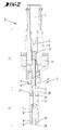
- FIG. 2 , 2a and 2b A second preferred embodiment of an injection valve 1 comprising a valve assembly arrangement 2 according to the invention is shown by Figures 2 , 2a and 2b .
- a first magnetic member 20 is axially fixed at the valve needle 18 and a second magnetic member 21 is axially fixed at the valve housing section 14 of the second valve assembly 4.
- the second magnetic member 21 consists of permanent-magnetic material, i.e. is a permanent magnet 26
- the first magnetic member 20 consists of a ferromagnetic material, i.e. is a ferromagnet - like for example steel or the like. It is clear that the function of the second valve assembly 4 and of the complete injection valve 1 is the same as explained with regard to the first embodiment.
- FIG. 3 is it shown a third preferred embodiment of an injection valve 1 comprising a valve assembly arrangement 2 according to the invention.
- a ring-shaped first magnetic member 20 is axially fixed at the valve needle 18 and a ring-shaped second magnetic member 21 is axially fixed at the valve housing section 14 of the second valve assembly 4.
- the axial magnetic orientation of members 20, 21 is such that they are attracted to each other by the magnetic forces.
- an additional ring-shaped member 31 to cooperate as a stopper with the surface 30 of the step 29.
- the member 31 is connected to the valve needle 18 at a side 32 of the first magnetic member 20 wherein said side 32 is facing the axial end area 16.
- the first magnetic member 20 consists of permanent-magnetic material and also the second magnetic member 21 consists of permanent-magnetic material.
- the axial magnetic polarization of members 20 and 21 is such that they are attracted to each other by the magnetic forces.
- the magnetic closing function is however the same as explained with regard to the first and second embodiments.
Landscapes
- Engineering & Computer Science (AREA)
- Chemical & Material Sciences (AREA)
- Combustion & Propulsion (AREA)
- Mechanical Engineering (AREA)
- General Engineering & Computer Science (AREA)
- Physics & Mathematics (AREA)
- Electromagnetism (AREA)
- Fuel-Injection Apparatus (AREA)
Abstract
The invention regards a valve assembly arrangement (2) for an injection valve (1), comprising a first valve assembly (3) and a second valve assembly (4), wherein the latter is axially arranged adjacent to and coupled to the first valve assembly (3), wherein the second valve assembly comprises a valve housing section (14) having an orifice (15) at an axial end area (16) of the valve housing (5), the second valve assembly comprises a cavity (17) in its valve housing section and the second valve assembly comprises a valve needle (18) being axially movable in said cavity between a closing position and other positions. The invention suggests that the second valve assembly (4) comprises a first magnetic member (20) being fixed to the valve needle (18) of the second valve assembly (4), that the second valve assembly (4) comprises a second magnetic member (21) being fixed to the valve housing section (14) of the second valve assembly (4), that at least one of the first magnetic member (20) and the second magnetic member (21) includes permanent-magnetic material or consists of permanent-magnetic material, and that the second valve assembly (4) is of the outward opening type and the first magnetic member (20) is disposed at a side (27) of the second magnetic member (21) wherein said side (27) is facing the axial end area (16).
Description
- This invention relates to a valve assembly arrangement for an injection valve, the valve assembly arrangement having a central longitudinal axis and comprising a first valve assembly and a second valve assembly, wherein the second valve assembly is axially arranged adjacent to and coupled to the first valve assembly, wherein the valve assembly arrangement comprises a valve housing, wherein the second valve assembly comprises a valve housing section having an orifice at an axial end area of the valve housing, the second valve assembly comprises a cavity in its valve housing section and the second valve assembly comprises a valve needle being axially movable in said cavity between a closing position and other positions.
- The invention also relates to an injection valve comprising a valve assembly arrangement.
- Injection valves are in wide spread use, in particular for internal combustion engines where they may be arranged in order to dose a fluid into an intake manifold of the internal of the internal combustion engine or directly into a combustion chamber of a cylinder of an internal combustion engine. Injection valves are manufactured in various forms in order to satisfy the various needs for the various combustion engines. Injection valves may accommodate an actuator for actuating a needle of the injection valve, which way, for example, be an electromagnetic actuator or a piezoelectric actuator.
- In order to enhance the combustion process in view of the creation of unwanted emissions, respective injection valves may be adapted to dose fluids under very high pressures.
- In the prior art there are known valve assembly arrangements comprising a passive valve and active valve which is upstream to the passive one. In such combinations the passive valve is used to release fuel or gas (i.e. fluid) without being directly controlled but following to actuation of the upstream valve. Usually the upstream valve is an active valve, i.e. for example a valve enabling active control by an electromagnet or the like. Very often the passive valve is placed to protect an upstream valve to be exposed to difficult environmental conditions. The opening of the passive valve occurs when the upstream valve releases pressurized fuel or gas which by means of the pressure energy opens the passive valve.
- Such a valve assembly arrangement is known from
WO 2013/083626 A1 . It comprises a first active valve assembly including an actuator and a second passive valve assembly. The closing function of the passive valve assembly is performed by a pre-compressed spring which keeps the passive valve normally closed. The spring load defines under which pressure conditions the passive valve begins to open and also when the passive begins to close. According to the spring load, when the passive valve closes, inside the passive valve body it may remain a residual pressure because of fuel or gas which has not been delivered. If the passive valve is exposed to a dynamic environment the external pressure changes, like inside a cylinder head exposed to the combustion chamber of a DI (DI = direct injection, i.e. the fuel or gas is injected directly into the combustion chamber) combustion engine, the residual pressure inside the valve could re-open the passive valve for releasing the remaining pressurized fuel or gas which would generate an uncontrolled release function. Up to now this problem has been solved by limiting the operative range of the pressure or by providing a controlled passive valve. - It is an object of the invention to provide an improved valve assembly arrangement for an injection valve and to provide an injection valve comprising such improved valve assembly arrangement. In particular, an object of the invention is that by such improvement the known disadvantageous limitations are removed as far as possible.
- In order to achieve the object, the present invention provides a generic valve assembly arrangement for an injection valve as mentioned at the beginning wherein the second valve assembly comprises a first magnetic member being fixed to the valve needle of the second valve assembly and wherein the second valve assembly comprises a second magnetic member being fixed to the valve housing section of the second valve assembly. The invention suggests that at least one of the first magnetic member and the second magnetic member includes a permanent magnet or consists of a permanent magnet.
- Expediently, a closing force on the valve needle of the second valve assembly may be generated by the permanent magnet, in particular by attracting the first magnetic member towards the second magnetic member or vice versa. Preferably, the closing force on the valve needle is solely effected by the permanent magnet. The second valve assembly is in particular operated without a spring acting on the valve needle of the second valve assembly for moving the valve needle to the closing position.
- In a preferred embodiment the second valve assembly is of the outward opening type and the first magnetic member is disposed at a side of the second magnetic member wherein said side is facing the axial end area. In other words the first magnetic member may be disposed at a space which is adjacent to the second magnetic member in an axial direction towards an axial end area of the valve assembly arrangement for dispensing the fluid. In an alternative embodiment the second valve assembly may be of the inward opening type and the second magnetic member may be disposed at a side of the first magnetic member wherein said side is facing the axial end area.
- In the preferred first embodiment and in the alternative embodiment the invention solves the above mentioned problem by means of a closing force of the second valve assembly (i.e. of the passive valve) which is at the maximum value when the second valve assembly is closed. Compared thereto the closing force is reduced when the second valve assembly is in an open condition. This allows to keep the second valve assembly closed when it is not supplied by pressurized fuel or gas from the first valve assembly and it allows to let the second valve assembly open as long as possible before the closing function has to be performed.
- Compared to the valve assembly arrangement known from the prior art, the closing spring is replaced in the passive valve assembly by a passive valve design closing mechanism including at least one permanent magnet. The at least one permanent magnet is installed with the function to attract the valve needle of the second valve assembly to its closing position. By means of the permanent magnet, it is possible that the maximum closing force is generated when the valve needle of the second valve assembly is in its closed position. When the valve needle is in its full open position, the closing force is reduced and hence it is possible to increase the pressure operative range of the passive second valve assembly without compromising the main closing function which is the sealing. Depending on the environment a permanent magnet for example can be placed on the moving part (in particular on the valve needle of the second valve assembly) or could be placed in a fixed position on the valve body or in particular on a section of a valve housing which belongs to the second valve assembly. In case enhanced performances are required it is possible to place two permanent magnets to support the closing function. The opening principle of the valve assembly arrangement is that the first valve assembly, which may be a standard injector, opens under control of an electronic signal and that the second, i.e. passive, valve assembly opens due to the pressure of the fluid which is passing through the opened first valve assembly (i.e. a pressure of gas fuel) when the force resulting from the pressure exceeds the magnetic closing force.
- The diagram shown by
figure 4 of this application provides a force displacement comparison for exemplary chosen embodiments of valve assembly arrangements. The ordinate represents the closing force in Newton and the abscissa shows a distance reduction to contact in millimeters wherein the starting point at 2 mm corresponds to "0 lift", i.e. a closed passive valve. The graph sp1 refers to a spring load of 5 N/mm (N) and the graph sp2 refers to a spring load of 10/mm (N). The symbol at P1 indicates that a higher force is needed to keep the passive valve open. Graph m1 represents the closing force of an exemplary embodiment of an inventive second valve assembly comprising a single magnet (N). Graph m2 represents the closing force of an exemplary embodiment of an inventive second valve assembly comprising a standard force double magnet (N). The diagram shows that the permanent magnet closing design allows having a lower closing force when the valve needle is open. This technical feature allows increasing the passive valve pressure operative range with stable performances. The term permanent-magnetic material refers to a magnetic material being permanently magnetized. The term permanent magnet could be used in the application instead of the wording permanent-magnetic material. - There are many possibilities for performing preferred modifications:
- It is preferred that the second valve assembly comprises a sealing portion at the axial end area of the valve housing and that the valve needle of the second valve assembly is adapted for preventing a fluid flow along the sealing portion in its closing position and is adapted for releasing a fluid flow along the sealing portion in other positions.
- In an embodiment it is provided that the first magnetic member and the second magnetic member contact each other or are closely spaced when the valve needle of the second valve assembly is in its closing position, and that an increasing movement of the valve needle of the second valve assembly away from its closing position results in an increasing distance between the first magnetic member and the second magnetic member. Advantageously, the closing force has its maximum in the closing condition. Within particular is expedient in an injection valve where the second valve assembly comprising the magnetic closing mechanism is of the outward opening type. The outward opening type means that the valve is opened when at the axial end area the tip of the valve needle moves in an outward direction, i.e. away from the valve housing. On the other hand, inward opening type means that the valve is open by a movement of the valve needle directed inwardly to the valve housing.
- In an embodiment the first magnetic member is a ring-like member being axially flipped on the valve needle of the second valve assembly. It is preferred that the second magnetic member is a ringlike member, i.e. in particular a ring-shaped member, wherein the valve needle of the second valve assembly in particular is extending in the hole of the second magnetic member in a manner axially movable relative to the second magnetic member. For providing fluid paths it is possible that the first magnetic member comprises at least one axial throughout opening and/or that the second magnetic member comprises at least one axial throughout opening.
- The invention suggests that at least one of the first magnetic member and the second magnetic member includes permanent-magnetic material or consists of permanent magnetic material. In other words, the first magnetic member and/or the second magnetic member includes permanent-magnetic material or consists of permanent magnetic material.
- In a first preferred embodiment it is provided that the first magnetic member includes permanent-magnetic material or consists of permanent-magnetic material and that the second magnetic member includes ferromagnetic material or consists of ferromagnetic material. Preferably, said ferromagnetic material is not permanently magnetized itself and for example may have soft magnetic properties like for example steel.
- In a second preferred embodiment it is possible that the second magnetic member includes permanent-magnetic material or consists of permanent-magnetic material and that the first magnetic member includes ferromagnetic material or consists of ferromagnetic material. Preferably, said ferromagnetic material is not permanently magnetized itself and for example may have soft magnetic properties like for example steel.
- In a preferred embodiment in order to achieve a special magnetic performance it is possible that the first magnetic member includes permanent-magnetic material or consists of permanent-magnetic material and that the second magnetic member includes permanent-magnetic material or consists of permanent-magnetic material.
- It is preferred that the valve housing comprises a step having a surface facing away from the axial end area and providing a stop for a stopper being connected to the valve needle of the second valve assembly. In an embodiment it is provided that the stopper is the first magnetic member or a member connected to the valve needle of the second valve assembly at a side of the first magnetic member wherein said side is facing the axial end area of the valve housing. This enables a limitation of the movement of the valve needle in an outward direction.
- Preferably the first magnetic member and the second magnetic member are positioned proximate to each other. This enables a strong magnetic force for closing the valve.
- It is preferred that the second valve assembly is coupled to the first valve assembly in such a fashion that the first valve assembly is operable to inject fluid into the second valve assembly for increasing a fluid pressure in the second valve assembly to open the second valve assembly to enable dispensing of fluid from the valve assembly arrangement.
- The first valve assembly may for example be a standard DI injector.
- It is preferred that the first valve assembly is of the inward opening type and comprises:
- a valve housing section comprising a cavity with a fluid inlet portion and a fluid outlet portion,
- a valve needle axially movable in the cavity of the first valve assembly, the valve needle of the first valve assembly preventing a fluid flow through the fluid outlet portion in a closing position and releasing a fluid flow through the fluid outlet portion in other positions,
- an actuator unit being adapted to actuate the valve needle of the first valve assembly, wherein the actuator unit in particular is an electro-magnetic actuator unit or is of the piezo type,
- and a spring for applying a force to the valve needle of the first valve assembly towards its closing position.
- The present invention also comprises an injection valve comprising a valve assembly arrangement wherein the valve assembly arrangement comprises one or more features explained above or in the following.
- The invention will now be described by way of example with reference to the accompanying drawings. These are as follows:
- Fig. 1
- is a schematic longitudinal sectional view of an inventive injection valve comprising an inventive valve assembly arrangement according to a first preferred embodiment,
- Fig. 1a
- is an enlarged view of a section of
Fig. 1 , also showing the injection valve closed, - Fig. 1b
- is a view similar to
Fig. 1a , however showing the injection valve opened, - Fig. 2
- is a schematic longitudinal sectional view of an inventive injection valve comprising an inventive valve assembly arrangement according to a second preferred embodiment,
- Fig. 2a
- is an enlarged view of a section of
Fig. 2 , also showing the injection valve closed, - Fig. 2b
- is a view similar to
Fig. 2a , however showing the injection valve opened, - Fig. 3
- is a schematic longitudinal sectional view of an inventive injection valve comprising an inventive valve assembly arrangement according to a third preferred embodiment,
- Fig. 3a
- is an enlarged view of a section of
Fig. 3 , also showing the injection valve closed, - Fig. 3b
- is a view similar to
Fig. 3a , however showing the injection valve opened, and - Fig. 4
- is a diagram showing a comparison of the closing force of different kinds of passive valve assemblies.
- In the figures corresponding or similar elements appearing in different illustrations are identified by the same reference numbers.
- With reference to
Figures 1 ,1a and 1b it is described by way of example a first embodiment of aninjection valve 1 according to the invention comprising a first preferred embodiment of avalve assembly arrangement 2 according to the present invention. Thevalve assembly arrangement 2 extends along a central longitudinal axis L and comprises afirst valve assembly 3 which is an active valve assembly and asecond valve assembly 4 which is a passive valve assembly. Thevalve assemblies valve assembly arrangement 2 comprises a valve housing which in its entirety is designated by thereference number 5. - The exemplary shown
injection valve 1 is in particular suitable for dosing a fluid, in particular for dosing fuel, to an internal combustion engine and comprises thevalve assembly arrangement 2. In the example thefirst valve assembly 3 is of the inward opening type and thesecond valve assembly 4 is of the outward opening type. Thefirst valve assembly 3 of the inward opening type is basically constructed like the active valve assembly known fromWO 2013/083626 A1 and, as described in this earlier application, is also similar to the injection valve described inEP 2 378 106 A1WO 2013/083626 A1 regarding said valve assembly is herewith incorporated in the disclosure of the present application. Accordingly, hereinafter only those details of thefirst valve assembly 3 of the inward opening type are described, which directly act together with thesecond valve assembly 4 of the outward opening type during operation. - The
first valve assembly 3 which is active operable and which is of the inward opening type comprises avalve housing section 6, i.e. a section of thevalve housing 5, comprising acavity 7 with afluid inlet portion 8 and afluid outlet portion 9. Avalve needle 10 of thefirst valve assembly 2 is axially movable in thecavity 7 so that it prevents a fluid flow through thefluid outlet portion 9 in a closing position and so that it releases a fluid flow through thefluid outlet portion 9 in other positions, i.e. in positions different from the closing position. Thefirst valve assembly 3 comprises anactuator unit 11 being adapted to actuate thevalve needle 10. In the shown example theactuator unit 11 is an electro-magnetic actuator unit. Theactuator unit 11 may be of the solenoid type and may correspond to those shown inFigure 1 ofWO 2013/083626 (i.e. it may include a coil which can be magnetized by applying an electrical current for attracting an armature of the first valve) or as shown inEP 2 378 106 A1spring 12 for applying a force to thevalve needle 10 towards its closing position. Theactuator unit 11 acts when being energized directly or indirectly on thevalve needle 10 in an axial direction thus moving thefirst valve needle 10 out from its closing position into an opening position for injecting fuel. Moving thevalve needle 10 into its closing position is established by means of saidspring 12 shown inFig. 1 , when theactuator unit 11 is de-energized. In the Figures for explaining the opening position respective gaps are schematically shown with exaggerated clearance for better clarity. - In a closing position of the
valve needle 10 it sealingly rests on aseat plate 13 thus preventing fluid flow through at least one injection nozzle arranged inside of and through theseat plate 13. The injection nozzle may be, for example, an injection hole. However, it may also be of some other type suitable for dosing fluid. - Axially along the central longitudinal axis L and adjacent to the
first valve assembly 3 of the inward opening type there is a arranged and fixedly coupled thesecond valve assembly 4 which is of the outward opening type. In an overall view this can be seen inFig. 1 which, likeFig. 1a , shows theinjection valve 1 closed. For comparison,Fig. 1b shows a section of theinjection valve 1 an opened state. Thesecond valve assembly 4 comprises avalve housing section 14 ofhousing 5 having anorifice 15 at anaxial end area 16 of thevalve housing 5. Further, thesecond valve assembly 4 comprises acavity 17 and avalve needle 18 which is axially movable in thecavity 17 between a closing position and other positions. Furthermore, thesecond valve assembly 4 comprises a sealingportion 19 at theaxial end area 16. Thevalve needle 18 is adapted for preventing a fluid flow along the sealingportion 19 in its closing position and is adapted for releasing a fluid flow along the sealingportion 19 in other positions. - The
second valve assembly 4 comprises a firstmagnetic member 20 which is formed like a ring and which is axially slipped and axially fixed on thevalve needle 18. The term axially fixed means that the fixation can withstand axial forces which are typical for operation.Member 20 may be fixed onvalve needle 18 for example by welding, by using a press fit or an adhesive or the like. The fixation is such that it can withstand axial forces. Furthermore, thesecond valve assembly 4 comprises a secondmagnetic member 21 which is also formed like a ring and which is axially fixed to thevalve housing section 14 of thesecond valve assembly 4. The fixation may be for example achieved by welding, press fit, an adhesive or the like and is capable to withstand axial forces. Thevalve needle 18 comprises anaxial end 22 facing away from theaxial end area 16 which extends in ahole 23 of the secondmagnetic member 21 in a manner axially movable relative to the secondmagnetic member 21 which may be achieved by an appropriate adaption of the diameters of thehole 23 and theend 22. As shown by the figures the firstmagnetic member 20 and the secondmagnetic member 21 respectively comprise throughout openings extending parallel to the longitudinal axis L for providing fluid paths. In the shown example the firstmagnetic member 20 consists of permanent-magnetic material, i.e. consists of a permanent magnet 26. The secondmagnetic member 21 consists of ferromagnetic material. In the embodiment, the firstmagnetic member 20 is disposed at aside 27 of the secondmagnetic member 21 wherein saidside 27 is facing theaxial end area 16. In other words the firstmagnetic member 20 is disposed at a space which is adjacent to the secondmagnetic member 21 in a direction towards theaxial end area 16. - The function of the
second valve assembly 4 is explained in the following.Figures 1 and1a show the injection valve in an operation condition when both thefirst valve assembly 3 and thesecond valve assembly 4 are closed. The firstmagnetic member 20 has been attracted by the secondmagnetic member 21 due to the axial magnetic force and has been moved to the secondmagnetic member 21 until bothmembers axial end 23 of thevalve needle 18 is axially movable within thehole 23. Firstmagnetic member 20 is fixed at an axial position on thevalve needle 18 so that in the state of contact betweenmembers opposite end 28 of thevalve needle 18 contacts thehousing 5 at theaxial end area 16 for sealing at the sealingportion 19. In this condition there is no gap betweenmembers cavity 17 the closing function nevertheless is ensured by the magnetic closing design because during the closing movement of thevalve needle 18 the magnetic attracting force betweenmembers - On the other hand, if the first valve assembly is opened by energizing the
actuator unit 11 by means of an electric current, fuel gas of a higher pressure will enter through thefluid outlet portion 9 of thefirst valve assembly 3 into thecavity 17 of thesecond valve assembly 4. The high fuel pressure will apply a resulting force to thevalve needle 18 which is exceeding the magnetic attracting force and accordingly thevalve needle 18 will move away from thefirst valve assembly 3 towards its opening position shown inFig. 1b . If theactuator unit 11 is de-energized and thefirst valve assembly 3 closed, most of the fuel gas contained incavity 17 will be dispensed. In the operation condition shown inFig. 1b , i.e. in the open condition, there is a gap betweenmembers cavity 17 decreases the resulting pressure force will fall below the actual magnetic force so that thevalve needle 18 will move towards thefirst valve assembly 3, i.e. towards its closing position. During such movement the axial force is increasing and hence is insuring safe closing function. - The
valve housing section 14 provides a ring-shapedstep 29 having asurface 30 extending perpendicularly to the longitudinal axis L and facing the firstmagnetic member 20. Thestep 29 and itssurface 30 provide an axial stop for the firstmagnetic member 20 in an axial direction towards theaxial end area 16. In other words, the firstmagnetic member 21 has also the function of an axial stopper which is connected to thevalve needle 18. Throughoutopenings - A second preferred embodiment of an
injection valve 1 comprising avalve assembly arrangement 2 according to the invention is shown byFigures 2 ,2a and 2b . Again, a firstmagnetic member 20 is axially fixed at thevalve needle 18 and a secondmagnetic member 21 is axially fixed at thevalve housing section 14 of thesecond valve assembly 4. However, differing from the first embodiment, in the second embodiment the secondmagnetic member 21 consists of permanent-magnetic material, i.e. is a permanent magnet 26, and the firstmagnetic member 20 consists of a ferromagnetic material, i.e. is a ferromagnet - like for example steel or the like. It is clear that the function of thesecond valve assembly 4 and of thecomplete injection valve 1 is the same as explained with regard to the first embodiment. - In
Figures 3 ,3a and 3b is it shown a third preferred embodiment of aninjection valve 1 comprising avalve assembly arrangement 2 according to the invention. Again, a ring-shaped firstmagnetic member 20 is axially fixed at thevalve needle 18 and a ring-shaped secondmagnetic member 21 is axially fixed at thevalve housing section 14 of thesecond valve assembly 4. The axial magnetic orientation ofmembers valve needle 18 adjacent to the firstmagnetic member 20 it is axially fixed an additional ring-shapedmember 31 to cooperate as a stopper with thesurface 30 of thestep 29. Themember 31 is connected to thevalve needle 18 at aside 32 of the firstmagnetic member 20 wherein saidside 32 is facing theaxial end area 16. In the third embodiment, the firstmagnetic member 20 consists of permanent-magnetic material and also the secondmagnetic member 21 consists of permanent-magnetic material. The axial magnetic polarization ofmembers - Regarding
Fig. 4 reference is made to the preceeding description. - All disclosed features are (for its own, but also in combination) relevant for the invention. The features of the dependent claims characterize also independent inventive improvements of the prior art, in particular for filing divisional applications on a basis of these claims.
Claims (15)
- A valve assembly arrangement (2) for an injection valve (1), the valve assembly arrangement (2) having a central longitudinal axis (L) and comprising a first valve assembly (3) and a second valve assembly (4), wherein the second valve assembly is axially arranged adjacent to and coupled to the first valve assembly (3),
wherein the valve assembly arrangement (3) comprises a valve housing (5),
wherein the second valve assembly comprises a valve housing section (14) having an orifice (15) at an axial end area (16) of the valve housing (5), the second valve assembly comprises a cavity (17) in its valve housing section and the second valve assembly comprises a valve needle (18) being axially movable in said cavity between a closing position and other positions,
characterized in that- the second valve assembly (4) comprises a first magnetic member (20) being fixed to the valve needle (18) of the second valve assembly (4),- the second valve assembly (4) comprises a second magnetic member (21) being fixed to the valve housing section (14) of the second valve assembly (4), and- at least one of the first magnetic member (20) and the second magnetic member (21) includes permanent-magnetic material or consists of permanent-magnetic material,and in that- either the second valve assembly (4) is of the outward opening type and the first magnetic member (20) is disposed at a side (27) of the second magnetic member (21) wherein said side (27) is facing the axial end area (16),- or the second valve assembly is of the inward opening type and the second magnetic member (21) is disposed at a side of the first magnetic member (20) wherein said side is facing the axial end area (16). - Valve assembly arrangement (2) according to claim 1, characterized in that the second valve assembly comprises a sealing portion (19) at the axial end area (16) of the valve housing (5) and that the valve needle (18) of the second valve assembly (4) is adapted for preventing a fluid flow along the sealing portion (19) in its closing position and is adapted for releasing a fluid flow along the sealing portion (19) in other positions.
- Valve assembly arrangement (2) according to any of the preceding claims, characterized in that- the first magnetic member (20) and the second magnetic member (21) contact each other or are closely spaced when the valve needle (18) of the second valve assembly (4) is in its closing position, and- an increasing movement of the valve needle (18) of the second valve assembly (4) away from its closing position results in an increasing distance between the first magnetic member (20) and the second magnetic member (21).
- Valve assembly arrangement (2) according to any of the preceding claims, characterized in that the first magnetic member (20) is a ringlike member being axially slipped on the valve needle (18) of the second valve assembly (4).
- Valve assembly arrangement (2) according to any of the preceding claims, characterized in that the second magnetic member (21) is a ringlike member, wherein the valve needle (18) of the second valve assembly (4) in particular is extending in the hole (23) of the second magnetic member (21) in a manner axially movable relative to the second magnetic member (21).
- Valve assembly arrangement (2) according to any of the preceding claims, characterized in that the first magnetic member (20) comprises at least one axial throughout opening and/or that the second magnetic member (21) comprises at least one axial throughout opening (24, 25).
- Valve assembly arrangement (2) according to any of the preceding claims 1-6, characterized in that the first magnetic member (20) includes permanent-magnetic material or consists of permanent-magnetic material and that the second magnetic member (21) includes ferromagnetic material or consists of ferromagnetic material.
- Valve assembly arrangement (2) according to any of the preceding claims 1-6, characterized in that the second magnetic member (21) includes permanent-magnetic material or consists of permanent-magnetic material and that the first magnetic member (20) includes ferromagnetic material or consists of ferromagnetic material.
- Valve assembly arrangement (2) according to any of the preceding claims 1-6, characterized in that the first magnetic member (20) includes permanent-magnetic material or consists of permanent-magnetic material and that the second magnetic member (21) includes permanent-magnetic material or consists of permanent-magnetic material.
- Valve assembly arrangement (2) according to any of the preceding claims, characterized in that the valve housing (5) comprises a step (29) having a surface (30) facing away from the axial end area (16) and providing a stop for a stopper being connected to the valve needle (18) of the second valve assembly (4).
- Valve assembly arrangement (2) according to claim 10, characterized in that the stopper being the first magnetic member (20) or a member (31) connected to the valve needle (18) of the second valve assembly (4) at a side (32) of the first magnetic member (20) wherein said side (32) is facing the axial end area (16) of the valve housing (5).
- Valve assembly arrangement (2) according to any of the preceding claims, characterized in that the first magnetic member (20) and the second magnetic member (21) are positioned proximate to each other.
- Valve assembly arrangement (2) according to any of the preceding claims, characterized in that the second valve assembly (4) is coupled to the first valve assembly (3) in such fashion that the first valve assembly (3) is operable to inject fluid into the second valve assembly (4) for increasing a fluid pressure in the second valve assembly (4) to open the second valve assembly (4) to enable dispensing of fluid from the valve assembly arrangement (2).
- Valve assembly arrangement (2) according to any of the preceding claims, characterized in that the first valve assembly (3) is of the inward opening type and comprises:- a valve housing section (6) comprising a cavity (7) with a fluid inlet portion (8) and a fluid outlet portion (9),- a valve needle (10) axially movable in the cavity (7) of the first valve assembly, the valve needle of the first valve assembly preventing a fluid flow through the fluid outlet portion (9) in a closing position and releasing a fluid flow through the fluid outlet portion in other positions,- an actuator unit (11) being adapted to actuate the valve needle (10) of the first valve assembly (3), wherein the actuator unit (11) in particular is an electro-magnetic actuator unit or is of the piezo type, and- a spring (12) for applying a force to the valve needle (10) of the first valve assembly towards its closing position.
- Injection valve (1) comprising a valve assembly arrangement (2) according to any one of the preceding claims.
Priority Applications (1)
| Application Number | Priority Date | Filing Date | Title |
|---|---|---|---|
| EP15189051.4A EP3153697A1 (en) | 2015-10-09 | 2015-10-09 | Valve assembly arrangement for an injection valve and injection valve |
Applications Claiming Priority (1)
| Application Number | Priority Date | Filing Date | Title |
|---|---|---|---|
| EP15189051.4A EP3153697A1 (en) | 2015-10-09 | 2015-10-09 | Valve assembly arrangement for an injection valve and injection valve |
Publications (1)
| Publication Number | Publication Date |
|---|---|
| EP3153697A1 true EP3153697A1 (en) | 2017-04-12 |
Family
ID=54291168
Family Applications (1)
| Application Number | Title | Priority Date | Filing Date |
|---|---|---|---|
| EP15189051.4A Withdrawn EP3153697A1 (en) | 2015-10-09 | 2015-10-09 | Valve assembly arrangement for an injection valve and injection valve |
Country Status (1)
| Country | Link |
|---|---|
| EP (1) | EP3153697A1 (en) |
Cited By (2)
| Publication number | Priority date | Publication date | Assignee | Title |
|---|---|---|---|---|
| EP3470657A1 (en) | 2017-10-10 | 2019-04-17 | Continental Automotive GmbH | Valve assembly, valve assembly arrangement, injection valve and method for injecting a fluid |
| CN119508074A (en) * | 2025-01-21 | 2025-02-25 | 中国空气动力研究与发展中心超高速空气动力研究所 | Isobaric fuel supply system for shock tunnel engine test and its design and test method |
Citations (9)
| Publication number | Priority date | Publication date | Assignee | Title |
|---|---|---|---|---|
| DE3139949A1 (en) * | 1981-02-26 | 1983-04-28 | Robert Bosch Gmbh, 7000 Stuttgart | Fuel injection nozzle for internal combustion engines |
| US4653720A (en) * | 1985-03-02 | 1987-03-31 | Robert Bosch Gmbh | Electromagnetically actuatable fuel injection valve |
| JPH0199967U (en) * | 1987-12-25 | 1989-07-05 | ||
| DE4023688A1 (en) * | 1990-07-26 | 1992-01-30 | Bosch Gmbh Robert | Needle valve for fuel injection nozzle - has two permanent magnets to damp out needle vibrations |
| US5353991A (en) * | 1989-06-21 | 1994-10-11 | General Motors Corporation | Solenoid actuated valve assembly |
| US5947091A (en) * | 1995-11-14 | 1999-09-07 | Robert Bosch Gmbh | Fuel injection device for an internal combustion engine |
| JP2004316503A (en) * | 2003-04-15 | 2004-11-11 | Mikuni Corp | Electronic control fuel injection device and fuel injection control method |
| EP2378106A1 (en) | 2010-04-13 | 2011-10-19 | Continental Automotive GmbH | Valve assembly for an injection valve and injection valve |
| WO2013083626A1 (en) | 2011-12-07 | 2013-06-13 | Continental Automotive Gmbh | Valve assembly arrangement for an injection valve and injection valve |
-
2015
- 2015-10-09 EP EP15189051.4A patent/EP3153697A1/en not_active Withdrawn
Patent Citations (9)
| Publication number | Priority date | Publication date | Assignee | Title |
|---|---|---|---|---|
| DE3139949A1 (en) * | 1981-02-26 | 1983-04-28 | Robert Bosch Gmbh, 7000 Stuttgart | Fuel injection nozzle for internal combustion engines |
| US4653720A (en) * | 1985-03-02 | 1987-03-31 | Robert Bosch Gmbh | Electromagnetically actuatable fuel injection valve |
| JPH0199967U (en) * | 1987-12-25 | 1989-07-05 | ||
| US5353991A (en) * | 1989-06-21 | 1994-10-11 | General Motors Corporation | Solenoid actuated valve assembly |
| DE4023688A1 (en) * | 1990-07-26 | 1992-01-30 | Bosch Gmbh Robert | Needle valve for fuel injection nozzle - has two permanent magnets to damp out needle vibrations |
| US5947091A (en) * | 1995-11-14 | 1999-09-07 | Robert Bosch Gmbh | Fuel injection device for an internal combustion engine |
| JP2004316503A (en) * | 2003-04-15 | 2004-11-11 | Mikuni Corp | Electronic control fuel injection device and fuel injection control method |
| EP2378106A1 (en) | 2010-04-13 | 2011-10-19 | Continental Automotive GmbH | Valve assembly for an injection valve and injection valve |
| WO2013083626A1 (en) | 2011-12-07 | 2013-06-13 | Continental Automotive Gmbh | Valve assembly arrangement for an injection valve and injection valve |
Cited By (2)
| Publication number | Priority date | Publication date | Assignee | Title |
|---|---|---|---|---|
| EP3470657A1 (en) | 2017-10-10 | 2019-04-17 | Continental Automotive GmbH | Valve assembly, valve assembly arrangement, injection valve and method for injecting a fluid |
| CN119508074A (en) * | 2025-01-21 | 2025-02-25 | 中国空气动力研究与发展中心超高速空气动力研究所 | Isobaric fuel supply system for shock tunnel engine test and its design and test method |
Similar Documents
| Publication | Publication Date | Title |
|---|---|---|
| EP2788614B1 (en) | Valve assembly arrangement for an injection valve and injection valve | |
| EP2535552B1 (en) | Valve assembly for an injection valve and injection valve | |
| CN111094737B (en) | Injector for injecting fuel | |
| CN102086826B (en) | Electromagnetic valve for controlling fuel injector or for regulating pressure of high-pressure fuel accumulator | |
| EP2852753B1 (en) | Valve assembly for an injection valve and injection valve | |
| EP1783356B1 (en) | Fuel injector | |
| CN109416003B (en) | Valve for injecting gaseous fuel | |
| EP2436908A1 (en) | Valve assembly for an injection valve and injection valve | |
| US8919372B2 (en) | Valve assembly for an injection valve and injection valve | |
| US9528610B2 (en) | Valve assembly for an injection valve and injection valve | |
| EP2597296B1 (en) | Valve assembly for an injection valve and injection valve | |
| EP2851551B1 (en) | Fluid injection valve | |
| CN103975157A (en) | Valve assemblies and control valves for control valves | |
| EP3507483B1 (en) | Fluid injector and needle for a fluid injector | |
| KR102139895B1 (en) | Injection valve with magnetic ring element | |
| EP2194543B1 (en) | Solenoid actuator | |
| CN101512140A (en) | Injector for injecting fuel | |
| KR102007016B1 (en) | Valve assembly and injection valve | |
| EP3156638B1 (en) | Fuel injector | |
| EP2067981B1 (en) | Valve assembly for an injection valve and injection valve | |
| KR20180082354A (en) | Solenoid valve for a fuel injection system, and high pressure fuel pump | |
| EP2863044B1 (en) | Injection valve | |
| US20030099562A1 (en) | A unit pump with an actuator carrier and an actuator carrier thereof | |
| EP2703633A1 (en) | Valve assembly for an injection valve and injection valve |
Legal Events
| Date | Code | Title | Description |
|---|---|---|---|
| PUAI | Public reference made under article 153(3) epc to a published international application that has entered the european phase |
Free format text: ORIGINAL CODE: 0009012 |
|
| AK | Designated contracting states |
Kind code of ref document: A1 Designated state(s): AL AT BE BG CH CY CZ DE DK EE ES FI FR GB GR HR HU IE IS IT LI LT LU LV MC MK MT NL NO PL PT RO RS SE SI SK SM TR |
|
| AX | Request for extension of the european patent |
Extension state: BA ME |
|
| STAA | Information on the status of an ep patent application or granted ep patent |
Free format text: STATUS: THE APPLICATION IS DEEMED TO BE WITHDRAWN |
|
| 18D | Application deemed to be withdrawn |
Effective date: 20171013 |