EP3153643A1 - Beckenvorrichtung mit wasserauslass - Google Patents
Beckenvorrichtung mit wasserauslass Download PDFInfo
- Publication number
- EP3153643A1 EP3153643A1 EP16171073.6A EP16171073A EP3153643A1 EP 3153643 A1 EP3153643 A1 EP 3153643A1 EP 16171073 A EP16171073 A EP 16171073A EP 3153643 A1 EP3153643 A1 EP 3153643A1
- Authority
- EP
- European Patent Office
- Prior art keywords
- pool
- water
- protrusion
- outlet valve
- protrusion block
- Prior art date
- Legal status (The legal status is an assumption and is not a legal conclusion. Google has not performed a legal analysis and makes no representation as to the accuracy of the status listed.)
- Granted
Links
Images







Classifications
-
- E—FIXED CONSTRUCTIONS
- E04—BUILDING
- E04H—BUILDINGS OR LIKE STRUCTURES FOR PARTICULAR PURPOSES; SWIMMING OR SPLASH BATHS OR POOLS; MASTS; FENCING; TENTS OR CANOPIES, IN GENERAL
- E04H4/00—Swimming or splash baths or pools
- E04H4/12—Devices or arrangements for circulating water, i.e. devices for removal of polluted water, cleaning baths or for water treatment
- E04H4/1209—Treatment of water for swimming pools
- E04H4/1218—Devices for removal of polluted water; Circumferential gutters
-
- E—FIXED CONSTRUCTIONS
- E04—BUILDING
- E04H—BUILDINGS OR LIKE STRUCTURES FOR PARTICULAR PURPOSES; SWIMMING OR SPLASH BATHS OR POOLS; MASTS; FENCING; TENTS OR CANOPIES, IN GENERAL
- E04H4/00—Swimming or splash baths or pools
- E04H4/12—Devices or arrangements for circulating water, i.e. devices for removal of polluted water, cleaning baths or for water treatment
- E04H4/1209—Treatment of water for swimming pools
- E04H4/1236—Bottom drains
-
- E—FIXED CONSTRUCTIONS
- E04—BUILDING
- E04H—BUILDINGS OR LIKE STRUCTURES FOR PARTICULAR PURPOSES; SWIMMING OR SPLASH BATHS OR POOLS; MASTS; FENCING; TENTS OR CANOPIES, IN GENERAL
- E04H4/00—Swimming or splash baths or pools
- E04H4/12—Devices or arrangements for circulating water, i.e. devices for removal of polluted water, cleaning baths or for water treatment
- E04H4/1209—Treatment of water for swimming pools
- E04H4/1245—Recirculating pumps for swimming pool water
-
- F—MECHANICAL ENGINEERING; LIGHTING; HEATING; WEAPONS; BLASTING
- F16—ENGINEERING ELEMENTS AND UNITS; GENERAL MEASURES FOR PRODUCING AND MAINTAINING EFFECTIVE FUNCTIONING OF MACHINES OR INSTALLATIONS; THERMAL INSULATION IN GENERAL
- F16L—PIPES; JOINTS OR FITTINGS FOR PIPES; SUPPORTS FOR PIPES, CABLES OR PROTECTIVE TUBING; MEANS FOR THERMAL INSULATION IN GENERAL
- F16L5/00—Devices for use where pipes, cables or protective tubing pass through walls or partitions
Definitions
- the present invention is related to a pool apparatus, and more particularly related to a pool apparatus for water outflow and inflow.
- Pools have a rather long history. There are various types of pools designed for different purposes such as for swimming or for spa. Some pools are made through fixed structure, such as digging a hole on the ground and making strengthened water-resistant surface. Some pools are installed temporarily. For example, large water-resistant plastic clothing may be accompanied with a supporting structure to form an accommodation structure of a pool.
- all water in a pool may be discharged, and then new water is filled into the pool.
- Another way is periodically or constantly channeling the water to a filter mechanism. After the water is filtered, the filtered water is channeled back to the pool.
- sucking force may suck human body, and further leave human body or their clothes sucked on the draining outlets, which may cause sucked body parts to become red and swollen, and even may cause unfortunate drowning accident.
- pool apparatuses provided in the present invention.
- a practical embodiment based on the invention is a pool apparatus containing a pool body, a water inlet, a water outlet, and an outlet valve.
- the pool body is used to hold water for users to do activities in the pool body.
- the pool body may allow one or many users to swim, play, or do spa in the pool.
- the water inlet is used to deliver water to the pool body.
- the water outlet is used to drain the pool water out of the pool body.
- the outlet valve covers the water outlet.
- the outlet valve has a drainage surface to drain water via the drainage surface out of the pool body with a draining direction.
- the outlet valve has a protrusion block that protrudes with a protruding distance opposite to the draining direction with respect to the drainage surface to reduce the risk of users being sucked at the outlet valve.
- the outlet valve has a main body portion to form the drainage surface.
- the protrusion block is set on the main body portion.
- the bottom portion of the protrusion block overlaps partially with the drainage surface.
- the main body portion includes at least a filter screen for draining water from the pool body.
- the protrusion block has a protrusion portion, extending with a protrusion distance from the drainage surface.
- the main body portion may include a circular structure.
- the protrusive distance of the protrusive portion corresponds with the diameter of the circular structure. It may be set over 5%, 10%, 20%, or others based on different pool sizes, functions of usage, or draining force.
- the circular structure may have a side surrounding part and a circular face, which are equipped with the filter structure to drain water out of the pool body.
- the protrusion portion of the protrusion block may include a top-surfaced filter to drain water out of the pool body.
- the protrusion block and the main body may be designed as an integral form or two separable structures. With the latter design, the main body may have a thorough hole to assemble the protrusion block.
- the protrusion block may have various shapes.
- the protrusion portion of the protrusion block may be a dome structure or a cone structure.
- the protrusion portion of the protrusion block may also be designed as including a supportive blocking frame.
- This supportive blocking frame may form a separating space, which separates a user from the drainage surface to keep the predetermined distance, and keeps the water flowing through the separating space and entering the drainage surface.
- the protrusion portion of the protrusion block is not limited to one. It may have two or more than two protrusion portions.
- the bottom area of the protrusion block is smaller than that of the drainage surface.
- the bottom area of the protrusion block may be larger than the size of the drainage surface.
- the main body portion of the outlet valve may be a polygonal structure.
- the main body portion of the outlet valve and the protrusion block may have the same or different geometrical shapes.
- the pool apparatus may contain a filter pump linked to the water inlet and the water outlet of the pool body pool for offering a draining power to drain water out of the pool body from the water outlet
- the protrusive distance and the draining power have a predetermined correspondence. For example, the stronger the draining power of the filter pump gets, the larger numerical value the protrusive distance may be made.
- the size of the drainage surface may be enlarged to decrease the risk of the user getting stuck in the water outlet.
- a pool for people to use may have draining power over 1000 gallons/hour, or over 2000 gallons/hour.
- the pool apparatus further contains an emergency switch to switch off the filter pump used for drainage, or the water outlet.
- This emergency switch can be set at the location which is within the reach of the user's hands when the user is stuck in the drainage valve.
- FIG. 1 illustrates an embodiment of a pool apparatus according to the present invention.
- the pool apparatus contains a pool body 11 used to load water. Based on different design needs, it allows one or many users to doing different activities such as bathing, swimming, playing, etc.
- a filter pump 13 which drains the water out of the pool 11 through the outlet pipe 132.
- the filter pump 13 filters the water via filtering mechanism inside it, and then delivers the water into the pool body 11 through the inlet pipe 131.
- the pool has the pool body 151.
- the filter pump 159 is used for filtering and cleaning the water in the pool.
- the pool has two outlet valves 153, and 155. Parts of structures of the two outlet valves 153, 155 are set inside the pool body 151, and the others are set outside the pool body 151. They are assembled through the preset holes.
- the two outlet valves 153, 155 are linked to the filter pump 159 with a 1-to-2 connector through the pipe 158.
- the filter pump 159 pushes the filtered water into the pool body 151 through the inlet valve 157 to keep the water cycle complete.
- FIG. 1C illustrates an embodiment of a pool apparatus.
- the pool has the pool body 161.
- the filter pump 169 is used for filtering and cleaning the pool water. Different from the above-mentioned example, this pool has only one outlet valve 163. However, what is worth mentioning is that the pool may have more outlet valves or inlet valves under other design needs.
- One part of the structure of the outlet valve 163 is set in the pool body 161. Another part is set outside the pool body 161, and is assembled via preset holes.
- the outlet valve 163 is linked to the filter pump 169 through the pipeline 168.
- the filter pump 169 pushes the filtered water into the pool body 161 to keep the water cycle complete.
- the relative position and layout approach to the filter pump 13 and the pool body 11 may also be in other ways.
- the filter pump may be embedded in the pool body.
- the filter pump may be added with other functions as well such as increasing or decreasing the water temperature.
- the filter pump may be set statically or alternatively via the intelligent feedback system, or be operated by the user. These various designs should still be considered covered in the invention field.
- the pool apparatus may also not be equipped with the corresponding filter pump. Even so, in the process of draining water, suction might be formed in the drainage outlet, and the suction still may cause some risk to the users. For example, the water amount in the pool is over to some extent, or the ones who use the pool are kids with less strength, the elders, or those who lose most of their muscle strength because of health problems.
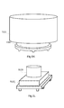
- Fig. 2 illustrates the flow relationship between the pool water and the filter pump.
- the pool body 21 is used to load water for users to do activities.
- the filter pump 22, which is linked to the pool body 21 gets water from the water outlet 211 in the pool body, and filters it. Then the filtered water is introduced into the pool body21 through the water inlet 212. From Fig. 2 , it can be known that the place where risks are likely to happen is the position of the water outlet 211 in the pool body pool 21.
- FIG 3 illustrates the reason why the outlet valve set in the pool body may cause risks to users.
- the outlet valve 31 is set covering a water outlet of a pool body. Therefore, the water will flow through the outlet valve 31, and into a filter pump or outside the pool body.
- This outlet valve 31 may be designed to be equipped with a multi-holed structure to let the water flow through the filter structure of these holes or the filter screen, and then flow into the water outlet.
- the outlet valve contains two parts, the main body portion 41 and the protrusion block 43.
- the main body portion 41 is similar to the outlet valve in Fig. 3 , containing the upper surface 411 and the surrounding side 412.
- the upper surface 411 and the surrounding side 412 may be set holes or the filter screen.
- the upper surface 411 is a circular-shaped with a circular draining surface corresponding to the lower covered water outlet. The water flows from the upper surface 411 or the surrounding side 412 into the outlet valve 41, and is channeled into the water outlet in the drainage direction.
- the protrusion block 43 has the circular upper surface 432 and the surrounding side 431.
- the protrusion block 43 protrudes upward a distance from the upper surface 411 of the main body portion 41 corresponding to the drainage surface in opposite to the drainage direction.
- the protrusive distance is the height of the surrounding part 431 of the protrusion block 43.
- the bottom side of the protrusion block 43 overlaps with the drainage surface, which corresponds to the upper surface 411 of the main body portion 41.
- the bottom size of the protrusion block 43 is smaller than that of the drainage surface with which the surface 411 of the main body portion 41 corresponds. But the latter embodiment may explain that it can have different arrangements in another design.
- the upper surface 432 of the protrusion block 43 and the surrounding side 431 can be set with structures such as holes or filter screens.
- the body 42 when the user uses it, the body 42 doesn't directly contact the upper surface 411 of the main body portion 41 of the outlet valve. By contrast, the user's body 42 will contact the upper face 432 of the protrusion block 43. Because the user's body 42 is blocked by the protrusion block 43, the user's body 42 will keep a distance from the main body portion 41 rather than directly cover most part of the outlet valve. As long as the water can flow out smoothly, the contact position between the body 42 and the outlet valve 41 does not produce exceeding suction so that the user's risk can be reduced.
- the outlet valve may have different designs, all of which may be used to control the way users' bodies make contact with the outlet valve when they use the pool, and further decrease the risk of usage.
- the outlet valve may have different designs, all of which may be used to control the way users' bodies make contact with the outlet valve when they use the pool, and further decrease the risk of usage.
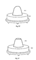
- FIG. 5A illustrates the structure of the outlet valve according to the present invention.
- This outlet valve has a main body portion 52 and a protrusion block 51.
- the protrusion block 51 overlaps with the main body portion 52, and is a protrusive distance higher than the drainage surface of the main body portion 52.
- Fig. 5B illustrates another structure of the outlet valve according to the present invention.
- the protrusion block 511 in the outlet valve of Fig. 5B is higher. Therefore, this design is safer, or capable of corresponding to stronger sucking force.
- the protrusive distance of the protrusion block 511 is designed, what is mainly considered if the relationship between its length and the size of the corresponding drainage surface of the body 521. Specifically speaking, the upper side of the main body is circular, and the ratio between the protrusive length and the diameter is over 5%, 10%, or 20%.
- the actual controlled parameter may be determined by different drainage forces.
- the power of the drainage suction can be up to 1000 gallons/hr, or even over 2000 gallons/hr. If the suction force is stronger, the relatively higher protrusive distance is set to ensure the lower risk.
- the main body portion of the outlet valve and the protrusion block may be designed in different ways.
- Fig 5C illustrates another structure of the outlet valve according to the present invention.
- the main body portion 532 is still disk-shaped, and the protrusion block 531 is a smaller cylinder with smaller diameter.
- Fig. 5D illustrates another structure of the outlet valve according to the present invention.
- the main body portion 542 is still disk-shaped, and the protrusion block 541 is an oval cone.
- Fig. 5E illustrates another structure of the outlet valve according to the present invention.
- the main body portion 552 is still a disk-shaped, and the protrusion block 551 is a cone structure.
- Fig. 5F illustrates another structure of the outlet valve according to the present invention.
- the main body portion 562 is still disk-shaped, and the protrusion block 561 is a cone with a platform upon it.
- Fig. 5G illustrates another structure of the outlet valve according to the present invention.
- the main body portion 572 is still disk-shaped, and the protrusion block 571 is a cone with a platform upon it, which extends upward from the main body portion 572.
- Fig. 5H illustrates another structure of the outlet valve according to the present invention.
- basically the height of the main body portion 582 is 0, and the protrusion block 581 is a cone with a platform upon it, which extends upward from the main body portion 582.
- the protrusion block 591 has a supporting blocking frame 5911.
- the supporting blocking frame 5911 has multiple cylinders to support a ring, and forms a space 5912 through the supporting blocking frame to keep a predetermined distance between the user and the drainage surface. Meanwhile, the supporting blocking frame 5911 keeps the water flowing through the separating space 5912 and entering the drainage surface of the main body portion 592.
- Fig 5J illustrates another structure of the outlet valve according to the present invention.
- the main body 5102 is still disk-shaped, and the protrusion block has several protrusion portions 51011, and 51012.
- Fig. 5K illustrates another structure of the outlet valve according to the present invention.
- the main body portion 5112 is still disk-shaped, and the bottom size of the protrusion block 5111 is on the upper face size of the main body portion 5112.
- the protrusion block 5111 covers the whole part of the main body portion 5112, under some requests, it still meets the safety if there are enough holes set on the side of the protrusive block 5111 and the side of the body 5112.
- Fig. 5L illustrates another structure of the outlet valve according to the present invention.
- the main body portion 5122 is multilateral-shaped, and the protrusion block 5121 remains the cylinder-shaped.
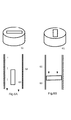
- an emergency switch may be set to switch off the filter pump or shut the drainage passage to contact the suction of drainage.
- the emergency knob is set near the water outlet of the main body pool. For example, it is set where hands can easily touch and operate it when the user gets stuck.
- the user can operate the emergency switch 61, change the angle of the valve 63 of the drainage passage 62, shut the current and decrease the suction immediately to discharge the emergency state.
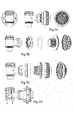
- Fig. 7A, 7B, 7C, and 7D illustrate the embodiment of different angles of an outlet valve.
- Fig. 7A contains the front view, the first side view, and the second side view of the assembled outlet valve.
- Fig. 7B illustrates the schematic perspective view of the dismantled elements of the outlet valve.
- Fig. 7C corresponds to Fig. 7B.
- Fig 7C illustrates the schematic perspective view from different angles of the dismantled elements of the outlet valve.
- Fig. 7D illustrates the section view of the outlet valve. From these figures, it can be known that the protrusion block of the outlet valve is directed set on the upper cover of the draining face to form an integrally formed structure.
- FIG. 8A, 8B, 8C, 8D, and 8E illustrate another embodiment of the schematic diagram from different angles of an outlet valve.
- Fig. 8A contains the front view, the first side view, and the second side view of the assembled outlet valve.
- Fig 8B, 8C, and 8D illustrate the schematic perspective view of elements from different angles after the outlet valve is dismantled.
- Fig. 8E illustrates the sectional view of the outlet valve. From these figures, it can be known that contrast to the previous embodiments, the protrusion block of the outlet valve protrudes through the holes of the drainage surface to form a protective effect.
Landscapes
- Engineering & Computer Science (AREA)
- Architecture (AREA)
- Water Supply & Treatment (AREA)
- Civil Engineering (AREA)
- Structural Engineering (AREA)
- General Engineering & Computer Science (AREA)
- Mechanical Engineering (AREA)
- Sink And Installation For Waste Water (AREA)
Applications Claiming Priority (2)
| Application Number | Priority Date | Filing Date | Title |
|---|---|---|---|
| CN201520784533.3U CN205558379U (zh) | 2015-10-10 | 2015-10-10 | 水池装置 |
| CN201510652485.7A CN106567564B (zh) | 2015-10-10 | 2015-10-10 | 水池装置 |
Publications (2)
| Publication Number | Publication Date |
|---|---|
| EP3153643A1 true EP3153643A1 (de) | 2017-04-12 |
| EP3153643B1 EP3153643B1 (de) | 2023-11-22 |
Family
ID=56081295
Family Applications (1)
| Application Number | Title | Priority Date | Filing Date |
|---|---|---|---|
| EP16171073.6A Active EP3153643B1 (de) | 2015-10-10 | 2016-05-24 | Beckenvorrichtung mit wasserauslass |
Country Status (2)
| Country | Link |
|---|---|
| US (1) | US9896854B2 (de) |
| EP (1) | EP3153643B1 (de) |
Cited By (1)
| Publication number | Priority date | Publication date | Assignee | Title |
|---|---|---|---|---|
| US9896854B2 (en) | 2015-10-10 | 2018-02-20 | Bestway Inflatables & Material Corp. | Pool apparatus |
Citations (7)
| Publication number | Priority date | Publication date | Assignee | Title |
|---|---|---|---|---|
| US3932281A (en) * | 1974-12-12 | 1976-01-13 | Pansini Andrew L | Leaf trap kit for swimming pools |
| US4658449A (en) * | 1985-09-19 | 1987-04-21 | Martin Daniel R | Proctective adapter for pool drain |
| US20100050335A1 (en) * | 2008-08-26 | 2010-03-04 | Baker Donald C | Cover and Sump Assembly For Preventing Suction Entrapment |
| US20100187169A1 (en) * | 2009-01-27 | 2010-07-29 | Brooks Hilton | Drain cover |
| CN202289680U (zh) * | 2011-09-02 | 2012-07-04 | 上海荣威塑胶工业有限公司 | 挂壁式水池过滤装置 |
| US8555989B1 (en) * | 2010-12-29 | 2013-10-15 | Harry Agajanian | Swimming pool skimmer port flow diverter and fire suppression system |
| EP2752527A1 (de) * | 2012-12-12 | 2014-07-09 | Chia-Yu Cheng | Filtergitter für einen Ablauf |
Family Cites Families (32)
| Publication number | Priority date | Publication date | Assignee | Title |
|---|---|---|---|---|
| US4503573A (en) * | 1983-07-11 | 1985-03-12 | Handzel James M | Swimming pool water circulation system |
| US4686718A (en) * | 1985-03-25 | 1987-08-18 | Aqua Systems, Inc. | Method and apparatus for automatically maintaining a predetermined desired level of water in a swimming pool, and the like |
| US5785846A (en) * | 1992-02-14 | 1998-07-28 | Caretaker Systems, Inc. | Venturi-powered filtration system for pools |
| US5577274A (en) * | 1995-05-17 | 1996-11-26 | Plotsky; David E. | Winterizing check valve system |
| US5809587A (en) | 1997-03-03 | 1998-09-22 | H-Tech, Inc. | Safety device for a suction outlet |
| US6022481A (en) * | 1996-09-11 | 2000-02-08 | Shasta Industries | Single pump pool cleaning system and method of simultaneously operating a full-function skimmer and multiple cleaning heads |
| US20090007325A9 (en) * | 2002-05-14 | 2009-01-08 | Goettl John M | Swimming pool drain |
| EP1807581A4 (de) | 2004-10-22 | 2013-04-10 | Balboa Water Group Inc | Trockensaug-montageanordnung |
| US20060230514A1 (en) | 2005-04-19 | 2006-10-19 | Meincke Jonathon E | Cover for a swimming pool main drain |
| CN201505471U (zh) | 2009-05-08 | 2010-06-16 | 明达实业(厦门)有限公司 | 多功能过滤器结构 |
| CN202708233U (zh) | 2012-07-04 | 2013-01-30 | 明达实业(厦门)有限公司 | 一种泄压止水阀结构 |
| CN202708091U (zh) | 2012-07-04 | 2013-01-30 | 明达实业(厦门)有限公司 | 一种止水阀结构 |
| CN203627900U (zh) | 2013-11-21 | 2014-06-04 | 明达实业(厦门)有限公司 | 一种泄水阀结构及应用该结构的充气水池控制箱 |
| EP3225764B1 (de) | 2013-07-18 | 2020-09-09 | Intex Marketing Ltd. | Aufblasbares heilbad |
| CN203640334U (zh) | 2013-12-30 | 2014-06-11 | 明达实业(厦门)有限公司 | 一种过滤罩结构及其应用该过滤罩结构的充气水池 |
| CN203583943U (zh) | 2013-11-21 | 2014-05-07 | 明达实业(厦门)有限公司 | 一种充气水池的排水机构 |
| EP3572600B1 (de) | 2013-12-05 | 2022-05-04 | Intex Recreation Corp. | Aufblasbares becken |
| CN203628111U (zh) | 2013-12-30 | 2014-06-04 | 明达实业(厦门)有限公司 | 一种水池管件的快装机构 |
| CN203654813U (zh) | 2013-12-30 | 2014-06-18 | 明达实业(厦门)有限公司 | 一种充气水池管路密闭结构 |
| CN204141859U (zh) | 2014-07-08 | 2015-02-04 | 明达实业(厦门)有限公司 | 一种可调式太阳能加热装置及应用该加热装置的加热水池 |
| CN204139662U (zh) | 2014-10-20 | 2015-02-04 | 明达实业(厦门)有限公司 | 一种具有喷射按摩水与气泡按摩水功能的按摩水池 |
| CN204326598U (zh) | 2014-12-23 | 2015-05-13 | 明达实业(厦门)有限公司 | 一种自发电的移动式水池 |
| CN204328168U (zh) | 2014-12-23 | 2015-05-13 | 明达实业(厦门)有限公司 | 一种内置式水位调节阀 |
| CN204910936U (zh) | 2015-08-27 | 2015-12-30 | 上海荣威塑胶工业有限公司 | 壁挂式水池过滤装置 |
| CA3037677C (en) | 2015-05-12 | 2021-05-18 | Intex Marketing Ltd. | Water spraying device for above ground pool |
| CN205000681U (zh) | 2015-05-12 | 2016-01-27 | 明达实业(厦门)有限公司 | 一种移动式水池 |
| CN106567564B (zh) | 2015-10-10 | 2020-07-03 | 上海荣威塑胶工业有限公司 | 水池装置 |
| US9896854B2 (en) | 2015-10-10 | 2018-02-20 | Bestway Inflatables & Material Corp. | Pool apparatus |
| CN205558379U (zh) | 2015-10-10 | 2016-09-07 | 上海荣威塑胶工业有限公司 | 水池装置 |
| CN205591600U (zh) | 2015-12-15 | 2016-09-21 | 明达实业(厦门)有限公司 | 泳池过滤罩 |
| CN205296923U (zh) | 2016-01-07 | 2016-06-08 | 明达实业(厦门)有限公司 | 一种带漏电保护的水池控制箱 |
| CN205678173U (zh) | 2016-06-02 | 2016-11-09 | 明达实业(厦门)有限公司 | 一种可排气的管路结构 |
-
2016
- 2016-05-12 US US15/153,174 patent/US9896854B2/en active Active
- 2016-05-24 EP EP16171073.6A patent/EP3153643B1/de active Active
Patent Citations (7)
| Publication number | Priority date | Publication date | Assignee | Title |
|---|---|---|---|---|
| US3932281A (en) * | 1974-12-12 | 1976-01-13 | Pansini Andrew L | Leaf trap kit for swimming pools |
| US4658449A (en) * | 1985-09-19 | 1987-04-21 | Martin Daniel R | Proctective adapter for pool drain |
| US20100050335A1 (en) * | 2008-08-26 | 2010-03-04 | Baker Donald C | Cover and Sump Assembly For Preventing Suction Entrapment |
| US20100187169A1 (en) * | 2009-01-27 | 2010-07-29 | Brooks Hilton | Drain cover |
| US8555989B1 (en) * | 2010-12-29 | 2013-10-15 | Harry Agajanian | Swimming pool skimmer port flow diverter and fire suppression system |
| CN202289680U (zh) * | 2011-09-02 | 2012-07-04 | 上海荣威塑胶工业有限公司 | 挂壁式水池过滤装置 |
| EP2752527A1 (de) * | 2012-12-12 | 2014-07-09 | Chia-Yu Cheng | Filtergitter für einen Ablauf |
Cited By (1)
| Publication number | Priority date | Publication date | Assignee | Title |
|---|---|---|---|---|
| US9896854B2 (en) | 2015-10-10 | 2018-02-20 | Bestway Inflatables & Material Corp. | Pool apparatus |
Also Published As
| Publication number | Publication date |
|---|---|
| EP3153643B1 (de) | 2023-11-22 |
| US9896854B2 (en) | 2018-02-20 |
| US20170101794A1 (en) | 2017-04-13 |
Similar Documents
| Publication | Publication Date | Title |
|---|---|---|
| US6588029B2 (en) | Safety drain guard for swimming pools and spas | |
| AU2003226409B2 (en) | Pool floor drain assembly for a suction-activated water circulation system | |
| US6751814B2 (en) | Whirlpool bath filter and suction device | |
| US20050246830A1 (en) | Flow-through bathtub | |
| US20080099387A1 (en) | Adjustable skimmer safety system | |
| CN205162915U (zh) | 一种移动式洗浴装置 | |
| US20070180604A1 (en) | Circular suction outlet assembly and cover | |
| EP3153643B1 (de) | Beckenvorrichtung mit wasserauslass | |
| US20120305498A1 (en) | Pool Skimmer Assembly | |
| CA2465820C (en) | Water feature construction | |
| CN106567564B (zh) | 水池装置 | |
| US10738494B1 (en) | Channel drain assembly | |
| CN205558379U (zh) | 水池装置 | |
| US20080073257A1 (en) | Pool skimmer apparatus and method | |
| US8647504B2 (en) | Filter and filter handle for use in water filtration systems | |
| US6796776B2 (en) | Pumping system and method with improved screen | |
| US9856667B2 (en) | Low gravity fed water system without submersed drains within the bathing chamber for pools and spas | |
| US7934273B1 (en) | Method for relieving suction force in a pool drain | |
| AU2018223210B2 (en) | Skimmer box assembly | |
| TWI481769B (zh) | 浴缸之溢流排水閥結構 | |
| US8128813B2 (en) | Self cleaning system for swim spas and hot tubs | |
| KR200436578Y1 (ko) | 안전 배수트랩 . | |
| US7220353B2 (en) | Skimmer with rotatable filter cartridge for spas and pools | |
| KR101411992B1 (ko) | 수막을 이용하여 외부로부터 차단된 독립공간 조성 장치 | |
| KR101802587B1 (ko) | 수조 여과장치 |
Legal Events
| Date | Code | Title | Description |
|---|---|---|---|
| PUAI | Public reference made under article 153(3) epc to a published international application that has entered the european phase |
Free format text: ORIGINAL CODE: 0009012 |
|
| STAA | Information on the status of an ep patent application or granted ep patent |
Free format text: STATUS: REQUEST FOR EXAMINATION WAS MADE |
|
| 17P | Request for examination filed |
Effective date: 20160621 |
|
| AK | Designated contracting states |
Kind code of ref document: A1 Designated state(s): AL AT BE BG CH CY CZ DE DK EE ES FI FR GB GR HR HU IE IS IT LI LT LU LV MC MK MT NL NO PL PT RO RS SE SI SK SM TR |
|
| AX | Request for extension of the european patent |
Extension state: BA ME |
|
| STAA | Information on the status of an ep patent application or granted ep patent |
Free format text: STATUS: EXAMINATION IS IN PROGRESS |
|
| 17Q | First examination report despatched |
Effective date: 20170519 |
|
| RAP3 | Party data changed (applicant data changed or rights of an application transferred) |
Owner name: BESTWAY INFLATABLES & MATERIAL CORP. |
|
| GRAP | Despatch of communication of intention to grant a patent |
Free format text: ORIGINAL CODE: EPIDOSNIGR1 |
|
| STAA | Information on the status of an ep patent application or granted ep patent |
Free format text: STATUS: GRANT OF PATENT IS INTENDED |
|
| INTG | Intention to grant announced |
Effective date: 20230613 |
|
| GRAS | Grant fee paid |
Free format text: ORIGINAL CODE: EPIDOSNIGR3 |
|
| GRAA | (expected) grant |
Free format text: ORIGINAL CODE: 0009210 |
|
| STAA | Information on the status of an ep patent application or granted ep patent |
Free format text: STATUS: THE PATENT HAS BEEN GRANTED |
|
| AK | Designated contracting states |
Kind code of ref document: B1 Designated state(s): AL AT BE BG CH CY CZ DE DK EE ES FI FR GB GR HR HU IE IS IT LI LT LU LV MC MK MT NL NO PL PT RO RS SE SI SK SM TR |
|
| RAP3 | Party data changed (applicant data changed or rights of an application transferred) |
Owner name: BESTWAY INFLATABLES & MATERIAL CORP. |
|
| REG | Reference to a national code |
Ref country code: GB Ref legal event code: FG4D |
|
| RIN1 | Information on inventor provided before grant (corrected) |
Inventor name: LIU, FENG |
|
| REG | Reference to a national code |
Ref country code: CH Ref legal event code: EP |
|
| REG | Reference to a national code |
Ref country code: DE Ref legal event code: R096 Ref document number: 602016084245 Country of ref document: DE |
|
| REG | Reference to a national code |
Ref country code: IE Ref legal event code: FG4D |
|
| REG | Reference to a national code |
Ref country code: LT Ref legal event code: MG9D |
|
| REG | Reference to a national code |
Ref country code: NL Ref legal event code: MP Effective date: 20231122 |
|
| PG25 | Lapsed in a contracting state [announced via postgrant information from national office to epo] |
Ref country code: GR Free format text: LAPSE BECAUSE OF FAILURE TO SUBMIT A TRANSLATION OF THE DESCRIPTION OR TO PAY THE FEE WITHIN THE PRESCRIBED TIME-LIMIT Effective date: 20240223 |
|
| PG25 | Lapsed in a contracting state [announced via postgrant information from national office to epo] |
Ref country code: IS Free format text: LAPSE BECAUSE OF FAILURE TO SUBMIT A TRANSLATION OF THE DESCRIPTION OR TO PAY THE FEE WITHIN THE PRESCRIBED TIME-LIMIT Effective date: 20240322 |
|
| PG25 | Lapsed in a contracting state [announced via postgrant information from national office to epo] |
Ref country code: LT Free format text: LAPSE BECAUSE OF FAILURE TO SUBMIT A TRANSLATION OF THE DESCRIPTION OR TO PAY THE FEE WITHIN THE PRESCRIBED TIME-LIMIT Effective date: 20231122 |
|
| REG | Reference to a national code |
Ref country code: AT Ref legal event code: MK05 Ref document number: 1633986 Country of ref document: AT Kind code of ref document: T Effective date: 20231122 |
|
| PG25 | Lapsed in a contracting state [announced via postgrant information from national office to epo] |
Ref country code: NL Free format text: LAPSE BECAUSE OF FAILURE TO SUBMIT A TRANSLATION OF THE DESCRIPTION OR TO PAY THE FEE WITHIN THE PRESCRIBED TIME-LIMIT Effective date: 20231122 |
|
| PG25 | Lapsed in a contracting state [announced via postgrant information from national office to epo] |
Ref country code: AT Free format text: LAPSE BECAUSE OF FAILURE TO SUBMIT A TRANSLATION OF THE DESCRIPTION OR TO PAY THE FEE WITHIN THE PRESCRIBED TIME-LIMIT Effective date: 20231122 |
|
| PG25 | Lapsed in a contracting state [announced via postgrant information from national office to epo] |
Ref country code: ES Free format text: LAPSE BECAUSE OF FAILURE TO SUBMIT A TRANSLATION OF THE DESCRIPTION OR TO PAY THE FEE WITHIN THE PRESCRIBED TIME-LIMIT Effective date: 20231122 |
|
| PG25 | Lapsed in a contracting state [announced via postgrant information from national office to epo] |
Ref country code: NL Free format text: LAPSE BECAUSE OF FAILURE TO SUBMIT A TRANSLATION OF THE DESCRIPTION OR TO PAY THE FEE WITHIN THE PRESCRIBED TIME-LIMIT Effective date: 20231122 Ref country code: LT Free format text: LAPSE BECAUSE OF FAILURE TO SUBMIT A TRANSLATION OF THE DESCRIPTION OR TO PAY THE FEE WITHIN THE PRESCRIBED TIME-LIMIT Effective date: 20231122 Ref country code: IS Free format text: LAPSE BECAUSE OF FAILURE TO SUBMIT A TRANSLATION OF THE DESCRIPTION OR TO PAY THE FEE WITHIN THE PRESCRIBED TIME-LIMIT Effective date: 20240322 Ref country code: GR Free format text: LAPSE BECAUSE OF FAILURE TO SUBMIT A TRANSLATION OF THE DESCRIPTION OR TO PAY THE FEE WITHIN THE PRESCRIBED TIME-LIMIT Effective date: 20240223 Ref country code: ES Free format text: LAPSE BECAUSE OF FAILURE TO SUBMIT A TRANSLATION OF THE DESCRIPTION OR TO PAY THE FEE WITHIN THE PRESCRIBED TIME-LIMIT Effective date: 20231122 Ref country code: BG Free format text: LAPSE BECAUSE OF FAILURE TO SUBMIT A TRANSLATION OF THE DESCRIPTION OR TO PAY THE FEE WITHIN THE PRESCRIBED TIME-LIMIT Effective date: 20240222 Ref country code: AT Free format text: LAPSE BECAUSE OF FAILURE TO SUBMIT A TRANSLATION OF THE DESCRIPTION OR TO PAY THE FEE WITHIN THE PRESCRIBED TIME-LIMIT Effective date: 20231122 Ref country code: PT Free format text: LAPSE BECAUSE OF FAILURE TO SUBMIT A TRANSLATION OF THE DESCRIPTION OR TO PAY THE FEE WITHIN THE PRESCRIBED TIME-LIMIT Effective date: 20240322 |
|
| PG25 | Lapsed in a contracting state [announced via postgrant information from national office to epo] |
Ref country code: SE Free format text: LAPSE BECAUSE OF FAILURE TO SUBMIT A TRANSLATION OF THE DESCRIPTION OR TO PAY THE FEE WITHIN THE PRESCRIBED TIME-LIMIT Effective date: 20231122 Ref country code: RS Free format text: LAPSE BECAUSE OF FAILURE TO SUBMIT A TRANSLATION OF THE DESCRIPTION OR TO PAY THE FEE WITHIN THE PRESCRIBED TIME-LIMIT Effective date: 20231122 Ref country code: PL Free format text: LAPSE BECAUSE OF FAILURE TO SUBMIT A TRANSLATION OF THE DESCRIPTION OR TO PAY THE FEE WITHIN THE PRESCRIBED TIME-LIMIT Effective date: 20231122 Ref country code: NO Free format text: LAPSE BECAUSE OF FAILURE TO SUBMIT A TRANSLATION OF THE DESCRIPTION OR TO PAY THE FEE WITHIN THE PRESCRIBED TIME-LIMIT Effective date: 20240222 Ref country code: LV Free format text: LAPSE BECAUSE OF FAILURE TO SUBMIT A TRANSLATION OF THE DESCRIPTION OR TO PAY THE FEE WITHIN THE PRESCRIBED TIME-LIMIT Effective date: 20231122 Ref country code: HR Free format text: LAPSE BECAUSE OF FAILURE TO SUBMIT A TRANSLATION OF THE DESCRIPTION OR TO PAY THE FEE WITHIN THE PRESCRIBED TIME-LIMIT Effective date: 20231122 |
|
| PG25 | Lapsed in a contracting state [announced via postgrant information from national office to epo] |
Ref country code: DK Free format text: LAPSE BECAUSE OF FAILURE TO SUBMIT A TRANSLATION OF THE DESCRIPTION OR TO PAY THE FEE WITHIN THE PRESCRIBED TIME-LIMIT Effective date: 20231122 |
|
| PG25 | Lapsed in a contracting state [announced via postgrant information from national office to epo] |
Ref country code: CZ Free format text: LAPSE BECAUSE OF FAILURE TO SUBMIT A TRANSLATION OF THE DESCRIPTION OR TO PAY THE FEE WITHIN THE PRESCRIBED TIME-LIMIT Effective date: 20231122 |
|
| PG25 | Lapsed in a contracting state [announced via postgrant information from national office to epo] |
Ref country code: SK Free format text: LAPSE BECAUSE OF FAILURE TO SUBMIT A TRANSLATION OF THE DESCRIPTION OR TO PAY THE FEE WITHIN THE PRESCRIBED TIME-LIMIT Effective date: 20231122 |
|
| PG25 | Lapsed in a contracting state [announced via postgrant information from national office to epo] |
Ref country code: SM Free format text: LAPSE BECAUSE OF FAILURE TO SUBMIT A TRANSLATION OF THE DESCRIPTION OR TO PAY THE FEE WITHIN THE PRESCRIBED TIME-LIMIT Effective date: 20231122 Ref country code: SK Free format text: LAPSE BECAUSE OF FAILURE TO SUBMIT A TRANSLATION OF THE DESCRIPTION OR TO PAY THE FEE WITHIN THE PRESCRIBED TIME-LIMIT Effective date: 20231122 Ref country code: RO Free format text: LAPSE BECAUSE OF FAILURE TO SUBMIT A TRANSLATION OF THE DESCRIPTION OR TO PAY THE FEE WITHIN THE PRESCRIBED TIME-LIMIT Effective date: 20231122 Ref country code: IT Free format text: LAPSE BECAUSE OF FAILURE TO SUBMIT A TRANSLATION OF THE DESCRIPTION OR TO PAY THE FEE WITHIN THE PRESCRIBED TIME-LIMIT Effective date: 20231122 Ref country code: EE Free format text: LAPSE BECAUSE OF FAILURE TO SUBMIT A TRANSLATION OF THE DESCRIPTION OR TO PAY THE FEE WITHIN THE PRESCRIBED TIME-LIMIT Effective date: 20231122 Ref country code: DK Free format text: LAPSE BECAUSE OF FAILURE TO SUBMIT A TRANSLATION OF THE DESCRIPTION OR TO PAY THE FEE WITHIN THE PRESCRIBED TIME-LIMIT Effective date: 20231122 Ref country code: CZ Free format text: LAPSE BECAUSE OF FAILURE TO SUBMIT A TRANSLATION OF THE DESCRIPTION OR TO PAY THE FEE WITHIN THE PRESCRIBED TIME-LIMIT Effective date: 20231122 |
|
| REG | Reference to a national code |
Ref country code: DE Ref legal event code: R097 Ref document number: 602016084245 Country of ref document: DE |
|
| PLBE | No opposition filed within time limit |
Free format text: ORIGINAL CODE: 0009261 |
|
| STAA | Information on the status of an ep patent application or granted ep patent |
Free format text: STATUS: NO OPPOSITION FILED WITHIN TIME LIMIT |
|
| PG25 | Lapsed in a contracting state [announced via postgrant information from national office to epo] |
Ref country code: SI Free format text: LAPSE BECAUSE OF FAILURE TO SUBMIT A TRANSLATION OF THE DESCRIPTION OR TO PAY THE FEE WITHIN THE PRESCRIBED TIME-LIMIT Effective date: 20231122 |
|
| 26N | No opposition filed |
Effective date: 20240823 |
|
| PG25 | Lapsed in a contracting state [announced via postgrant information from national office to epo] |
Ref country code: SI Free format text: LAPSE BECAUSE OF FAILURE TO SUBMIT A TRANSLATION OF THE DESCRIPTION OR TO PAY THE FEE WITHIN THE PRESCRIBED TIME-LIMIT Effective date: 20231122 |
|
| REG | Reference to a national code |
Ref country code: CH Ref legal event code: PL |
|
| PG25 | Lapsed in a contracting state [announced via postgrant information from national office to epo] |
Ref country code: MC Free format text: LAPSE BECAUSE OF FAILURE TO SUBMIT A TRANSLATION OF THE DESCRIPTION OR TO PAY THE FEE WITHIN THE PRESCRIBED TIME-LIMIT Effective date: 20231122 |
|
| PG25 | Lapsed in a contracting state [announced via postgrant information from national office to epo] |
Ref country code: LU Free format text: LAPSE BECAUSE OF NON-PAYMENT OF DUE FEES Effective date: 20240524 |
|
| PG25 | Lapsed in a contracting state [announced via postgrant information from national office to epo] |
Ref country code: MC Free format text: LAPSE BECAUSE OF FAILURE TO SUBMIT A TRANSLATION OF THE DESCRIPTION OR TO PAY THE FEE WITHIN THE PRESCRIBED TIME-LIMIT Effective date: 20231122 Ref country code: LU Free format text: LAPSE BECAUSE OF NON-PAYMENT OF DUE FEES Effective date: 20240524 Ref country code: CH Free format text: LAPSE BECAUSE OF NON-PAYMENT OF DUE FEES Effective date: 20240531 |
|
| REG | Reference to a national code |
Ref country code: BE Ref legal event code: MM Effective date: 20240531 |
|
| PG25 | Lapsed in a contracting state [announced via postgrant information from national office to epo] |
Ref country code: IE Free format text: LAPSE BECAUSE OF NON-PAYMENT OF DUE FEES Effective date: 20240524 |
|
| PG25 | Lapsed in a contracting state [announced via postgrant information from national office to epo] |
Ref country code: BE Free format text: LAPSE BECAUSE OF NON-PAYMENT OF DUE FEES Effective date: 20240531 |
|
| PGFP | Annual fee paid to national office [announced via postgrant information from national office to epo] |
Ref country code: DE Payment date: 20250513 Year of fee payment: 10 |
|
| PGFP | Annual fee paid to national office [announced via postgrant information from national office to epo] |
Ref country code: GB Payment date: 20250521 Year of fee payment: 10 |
|
| PGFP | Annual fee paid to national office [announced via postgrant information from national office to epo] |
Ref country code: FR Payment date: 20250530 Year of fee payment: 10 |
|
| PG25 | Lapsed in a contracting state [announced via postgrant information from national office to epo] |
Ref country code: CY Free format text: LAPSE BECAUSE OF FAILURE TO SUBMIT A TRANSLATION OF THE DESCRIPTION OR TO PAY THE FEE WITHIN THE PRESCRIBED TIME-LIMIT; INVALID AB INITIO Effective date: 20160524 |
|
| PG25 | Lapsed in a contracting state [announced via postgrant information from national office to epo] |
Ref country code: HU Free format text: LAPSE BECAUSE OF FAILURE TO SUBMIT A TRANSLATION OF THE DESCRIPTION OR TO PAY THE FEE WITHIN THE PRESCRIBED TIME-LIMIT; INVALID AB INITIO Effective date: 20160524 |
|
| PG25 | Lapsed in a contracting state [announced via postgrant information from national office to epo] |
Ref country code: FI Free format text: LAPSE BECAUSE OF FAILURE TO SUBMIT A TRANSLATION OF THE DESCRIPTION OR TO PAY THE FEE WITHIN THE PRESCRIBED TIME-LIMIT Effective date: 20231122 |