EP3153443A1 - A method and an arrangement for controlling an elevator machinery brake - Google Patents
A method and an arrangement for controlling an elevator machinery brake Download PDFInfo
- Publication number
- EP3153443A1 EP3153443A1 EP15188881.5A EP15188881A EP3153443A1 EP 3153443 A1 EP3153443 A1 EP 3153443A1 EP 15188881 A EP15188881 A EP 15188881A EP 3153443 A1 EP3153443 A1 EP 3153443A1
- Authority
- EP
- European Patent Office
- Prior art keywords
- brake
- control circuit
- inductor
- brake control
- current
- Prior art date
- Legal status (The legal status is an assumption and is not a legal conclusion. Google has not performed a legal analysis and makes no representation as to the accuracy of the status listed.)
- Granted
Links
Images


Classifications
-
- B—PERFORMING OPERATIONS; TRANSPORTING
- B66—HOISTING; LIFTING; HAULING
- B66B—ELEVATORS; ESCALATORS OR MOVING WALKWAYS
- B66B1/00—Control systems of elevators in general
- B66B1/24—Control systems with regulation, i.e. with retroactive action, for influencing travelling speed, acceleration, or deceleration
- B66B1/28—Control systems with regulation, i.e. with retroactive action, for influencing travelling speed, acceleration, or deceleration electrical
- B66B1/32—Control systems with regulation, i.e. with retroactive action, for influencing travelling speed, acceleration, or deceleration electrical effective on braking devices, e.g. acting on electrically controlled brakes
Definitions
- the invention relates to a method and an arrangement for controlling an elevator machinery brake.
- An elevator comprises typically a car, an elevator shaft, a machine room, lifting machinery, ropes, and a counter weight.
- the elevator car is supported on a sling surrounding the car.
- the lifting machinery comprises a sheave, a machinery brake and an electric motor for rotating the sheave.
- the lifting machinery moves the car in a vertical direction upwards and downwards in the vertically extending elevator shaft.
- the sling and the car are carried by the ropes, which connect the car to the counter weight.
- the sling of the car is further supported with gliding means at guide rails extending in the vertical direction in the shaft.
- the gliding means can comprise rolls rolling on the guide rails or gliding shoes gliding on the guide rails when the elevator car is moving upwards and downwards in the elevator shaft.
- the guide rails are attached with fastening brackets at the side wall structures of the elevator shaft.
- the gliding means engaging with the guide rails keep the car in position in the horizontal plane when the car moves upwards and downwards in the elevator shaft.
- the counter weight is supported in a corresponding way on guide rails attached on the wall structure of the shaft.
- the car transports people and/or goods between the landings in the building.
- the elevator shaft can be formed so that the wall structure is formed of solid walls or so that the wall structure is formed of an open steel structure.
- Electromechanical drum brakes and disc brakes are typically used as machinery brakes in elevators.
- An electromechanical machinery brake comprises normally stationary brake shoes acting on a brake surface rotating with the sheave. The brake shoes are pressed against the brake surface by means of a mechanical force e.g. a spring and released from the brake surface by the force of an electromagnet.
- the electromagnet comprises one or several coils and an armature. The electromagnet can be energized with an electric current, whereby a magnetic field is produced in the electromagnet. The magnetic field will attract a counterpart of the armature. The counterpart of the armature moves in the opposite direction by a mechanical force when the electric current is disrupted.
- the brake shoes can be mechanically connected to the counterpart of the armature.
- the machinery brake will automatically be engaged i.e. the brake shoes will be pressed against the brake surface when the power supply to the coils of the machinery brake is for some reason disrupted.
- the power supply to the coils can be disrupted on purpose by opening a switch when the intention is to use the machinery brake to hold the elevator car at a desired landing.
- the power supply to the coils can, however, also be disrupted unintentionally due to a black-out in the power supply to the elevator.
- the machinery brake will thus be activated automatically stopping the movement of the elevator car when the black-out occurs.
- a machinery brake in an elevator comprises two electromechanical machinery brakes for safety reasons. This means that two brake coils are controlled by the elevator brake control circuit.
- the elevator car can in a black-out or emergency stop situation be stopped in two ways in prior art solutions.
- Both machinery brakes can be caused to brake rapidly. This means that the coils in the brakes should be deenergized rapidly. This can be done by connecting each coil to a circuit producing a high reverse voltage causing a rapid decrease of the current in the coil, whereby the mechanical force will cause the machinery brake to brake rapidly.
- the machinery brake can alternatively be caused to brake slowly by generating a low reverse voltage e.g. with a diode, whereby the current decreases slowly in the coil of the machinery brake.
- An object of the present invention is to present a novel method and a novel arrangement for controlling the braking of an elevator machinery brake.
- the method for controlling an elevator machinery brake is characterized by what is stated in the characterizing portion of claim 1.
- the brake control system in the method for controlling an elevator machinery brake comprising two brakes comprises:
- the method for controlling the elevator machinery brake comprising two brakes comprises:
- the brake control system in the arrangement for controlling an elevator machinery brake comprising two brakes comprises:
- the method and the arrangement provides for a possibility to control the retardation of the elevator car in a black-out or emergency stop situation so that a smooth braking of the machinery brake and thereby a smooth retardation of the elevator car can be achieved.
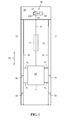
- Fig. 1 shows a vertical cross section of an elevator.
- the elevator comprises a car 10, an elevator shaft 20, a machine room 30, lifting machinery 40, ropes 41, and a counter weight 42.
- the car 10 is supported on a sling 11 surrounding the car 10.
- the lifting machinery 40 comprises a sheave 43, a machinery brake 100 and an electric motor 44 for rotating the sheave 43 via a shaft 45.
- the lifting machinery 40 moves the car 10 in a vertical direction S1 upwards and downwards in the vertically extending elevator shaft 20.
- the sling 11 and the car 10 within it are carried by the ropes 41, which connect the car 10 to the counter weight 42.
- the sling 11 of the car 10 is further supported with gliding means 70 at guide rails 50 extending in the vertical direction in the shaft 20.
- the figure shows two guide rails 50 at opposite sides of the car 10.
- the gliding means 70 can comprise rolls rolling on the guide rails 50 or gliding shoes gliding on the guide rails 50 when the car 10 is moving upwards and downwards in the elevator shaft 20.
- the guide rails 50 are attached with fish plates and fastening brackets 60 to the side wall structures 21 in the elevator shaft 20.
- the figure shows only two fastening brackets 60, but there are several fastening brackets 60 along the height of each guide rail 50.
- the gliding means 70 engaging with the guide rails 50 keep the car 10 in position in the horizontal plane when the car 10 moves upwards and downwards in the elevator shaft 20.
- the counter weight 42 is supported in a corresponding way on guide rails attached on the wall structure 21 of the shaft 20.
- the car 10 transports people and/or goods between the landings in the building.
- the elevator shaft 20 can be formed so that the wall structure 21 is formed of solid walls or so that the wall structure 21 is formed of an open
- FIG 2 shows a block diagram of the main parts in a control system of an elevator.
- the elevator car 10 is carried by the ropes 41, which connect the car 10 to the counter weight 42.
- the ropes 41 pass over the sheave 43 shown in figure 1 .
- the sheave 43 is driven by the electric motor 44.
- the system comprises a machinery brake 100, a machinery brake control system 300, a frequency converter 400, and a main control system 500.
- the frequency converter 400 is connected to the electrical grid 200.
- the frequency converter 400 controls the rotation of the electric motor 44.
- the electric motor 44 is advantageously a permanent magnet synchronous motor 44.
- the frequency converter 400 controls the rotation of the electric motor 44.
- the speed of rotation and the direction of rotation of the rotor of the electric motor 44 are measured with a sensor 600, which is connected to the frequency converter 400.
- the sensor may be an encoder or a tachometer. Another possibility is to determine the movement of the rotor of the electric motor 44 from the position of the permanent magnets with a Hall-sensor or from a voltage or current measurement by calculating from the counter voltage of the electric motor 44.
- the frequency converter 400 also receives a rotational speed reference of the electric motor 44 from the main control system 500.
- the rotational reference speed data of the electric motor 44 is the target value of the rotational speed of the electric motor 44.
- the machinery brake control system 300 is used to control the electromagnetic machinery brake 100 of the elevator.
- the machinery brake control system 300 can e.g. be situated in connection with the control panel of the elevator or in connection with the main control unit 500 or in the vicinity of the machinery brake 100.
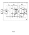
- FIG 3 shows an elevator machinery brake control system.
- the machinery brake control system 300 is formed of a rectifier bridge RB1, an intermediate circuit IC1, a first brake control circuit BC1 and a second brake control circuit BC2.
- the first brake control circuit BC1 controls the first brake inductor L1 in the first brake BR1.
- the second brake control circuit BC2 controls the second brake inductor L2 in the second brake BR2.
- the machinery brake 100 comprises thus two brakes BR1, BR2 supplied by a common voltage source i.e. the rectifier bridge RB1.
- the rectifier bridge RB1 converts the AC grid 200 voltage at the input terminals P1, P2 of the rectifier bridge RB1 into a direct voltage U1 at the DC voltage output terminals P3, P4 of the rectifier bridge RB1.
- the first DC voltage output terminal P3 is the positive pole of the DC output voltage U1 and the second DC voltage output terminal P4 is the negative pole of the DC output voltage U1.
- An intermediate circuit IC1 comprising a capacitor C1 is coupled in parallel to the DC voltage output terminals P3, P4 of the rectifier bridge RB1.
- the function of the capacitor C1 is to lessen the variation in (or to smooth) the rectified direct voltage U1 provided at the DC voltage output terminals P3, P4 of the rectifier bridge RB1.
- the direct voltage U1 provided at the DC voltage output terminals P3, P4 of the rectifier bridge RB1 and acting over the capacitor C1 in the intermediate circuit IC1 is then coupled to the input terminals P5, P6 of the first brake control circuit BC1 and to the input terminals P7, P8 of the second brake control circuit BC2.
- the first brake control circuit BC1 is coupled in parallel to the DC voltage output terminals P3, P4 of the rectifier bridge RB1 i.e. in parallel with the capacitor C1 of the intermediate circuit IC1.
- the second brake control circuit BC2 is coupled in parallel to the DC voltage output terminals P3, P4 of the rectifier bridge RB1 i.e. in parallel with the capacitor C1 of the intermediate circuit IC1.
- the first brake control circuit BC1 and the second brake control circuit BC2 are thus coupled in parallel to the DC voltage output terminals P3, P4 of the rectifier bridge RB1.
- the first inductor L1 in the first brake BR1 is coupled to the output terminals M1, M2 of the first brake control circuit BC1.
- the first brake control circuit BC1 comprises two different current paths i.e. a first, forward directed current path and a second, reverse directed current path.
- the first, forward directed current path passes from the first input terminal P5 of the first brake control circuit BC1 over a first switch S1 to the first output terminal M1 of the first brake control circuit BC1 and further through the first inductor L1 of the first brake BR1 to the second output terminal M2 of the first brake control circuit BC1 and further over a second switch S2 to the second input terminal P6 of the first brake control circuit BC1.
- the second, reverse directed current path passes from the second input terminal P6 of the first brake control circuit BC1 through a forward coupled second diode D2 to the first output terminal M1 of the first brake control circuit BC1 and further through the first inductor L1 of the first brake BR1 to the second output terminal M2 of the first brake control circuit BC1 and further through a forward coupled first diode D1 to the first input terminal P5 of the first brake control circuit BC1.
- the two current paths are formed by two parallel current circuits connected between the input terminals P5, P6 of the first brake control circuit BC1.
- the first current circuit comprises a series connection of the first diode D1 and the second switch S2.
- the cathode side of the first diode D1 is coupled to the first input terminal P5 of the first brake control circuit BC1 and the second side of the second switch S2 is coupled to the second input terminal P6 of the first brake control circuit BC1.
- the anode side of the first diode D1 is connected to the first side of the second switch S2.
- the second current circuit comprises a series connection of the first switch S1 and the second diode D2.
- the first side of the first switch S1 is coupled to the first input terminal P5 of the first brake control circuit BC1 and the anode side of the second diode D2 is coupled to the second input terminal P6 of the first brake control circuit BC1.
- the second side of the first switch S1 is connected to the cathode side of the second diode D2.
- the output terminals M1, M2 of the first brake control circuit BC1 are formed by the middle points M1, M2 of the first current circuit and the second current circuit.
- the middle point M1 of the first current circuit is located between the first diode D1 and the second switch S2.
- the middle point M2 of the second current circuit is located between the first switch S1 and the second diode D2.
- a first snubber RC1 is further coupled in parallel with the first brake inductor L1.
- the first snubber RC1 comprises in this embodiment a series connection of a diode and a varistor. A sudden interruption of the current flow to the first brake inductor L1 in the first brake BR1 will result in a high reverse voltage over the first brake inductor L1.
- the first snubber RC1 provides a short term alternative current path for the first brake inductor L1 to be discharged when the external current flow to the first brake inductor L1 is interrupted.
- the first snubber RC1 protects the capacitor C1 in the intermediate circuit IC1 and the first brake inductor L1 in the first brake BR1 by restricting over voltages produced in the first brake inductor L1 in the first brake BR1.
- the first snubber RC1 has as such no effect on the function of the invention.
- the second brake control circuit BC2 is identical with the first brake control circuit BC1.
- the second inductor L2 in the second brake BR2 is coupled to the output terminals M3, M4 of the second brake control circuit BC2.
- the second brake control circuit BC2 comprises two different current paths i.e. a first forward directed current path and a second reverse directed current path.
- the first, forward directed current path passes from the first input terminal P7 of the second brake control circuit BC2 over a first switch S3 to the first output terminal M3 of the second brake control circuit BC2 and further through the second inductor L2 of the second brake BR2 to the second output terminal M4 of the second brake control circuit BC2 and further over the second switch S4 to the second input terminal P8 of the second brake control circuit BC2.
- the second, reverse directed current path passes from the second input terminal P8 of the second brake control circuit BC2 through a forward coupled second diode D4 to the first output terminal M3 of the second brake control circuit BC2 and further through the second inductor L2 of the second brake BR2 to the second output terminal M4 of the second brake control circuit BC2 and further through a forward coupled second diode D3 to the first input terminal P7 of the second brake control circuit BC2.
- the two current paths are formed by two parallel current circuits connected between the input terminals P7, P8 of the second brake control circuit BC2.
- the first current circuit comprises a series connection of the first diode D3 and the second switch S4.
- the cathode side of the first diode D3 is coupled to the first input terminal P7 of the second brake control circuit BC2 and the second side of the second switch S4 is coupled to the second input terminal P8 of the second brake control circuit BC2.
- the anode side of the first diode D3 is connected to the first side of the second switch S4.
- the second current circuit comprises a series connection of the first switch S3 and the second diode D4.
- the first side of the first switch S3 is coupled to the first input terminal P7 of the second brake control circuit BC2 and the anode side of the second diode D4 is coupled to the second input terminal P8 of the second brake control circuit BC2.
- the second side of the first switch S3 is coupled to the cathode side of the second diode D4.
- the output terminals M3, M4 of the second brake control circuit BC2 are formed by the middle points M3, M4 of the first current circuit and the second current circuit.
- the middle point M3 of the first current circuit is located between the first diode D3 and the second switch S4.
- the middle point M2 of the second current circuit is located between the first switch S3 and the second diode D4.
- a second snubber RC2 is further coupled in parallel with the second brake inductor L2.
- the second snubber RC2 comprises in this embodiment a series connection of a diode and a varistor. A sudden interruption of the current flow to the second brake inductor L2 in the second brake BR2 will result in a high reverse voltage over the second brake inductor L2.
- the second snubber RC2 provides a short term alternative current path for the second brake inductor L2 to be discharged when the external current flow to the second brake inductor L2 is interrupted.
- the second snubber RC2 protects the capacitor C1 in the intermediate circuit IC1 and the second brake inductor L2 in the second brake BR2 by restricting over voltages produced in the second brake inductor L2 in the second brake BR2.
- the second snubber RC2 has as such no effect on the function of the invention.
- main switch S5 in the main voltage line before the input terminals P1, P2 of the rectifier bridge RB1. This is a part of the safety circuit of the elevator.
- the main control system 500 will close the main switch S5 when the main control system 500 receives a control signal to move the elevator car 10 and all the prerequisites relating to safety issues are fulfilled.
- the main switch S5 is opened when there is a black-out.
- the switches S1, S2, S3, S4 in the brake control circuits BC1, BC2 can be electromechanical switches e.g. relays or semiconductor switches e.g. mosfet or igbt switches.
- the machinery brake system 300 opens the brakes BR1, BR2 by leading a pick-up current I1 to the brake inductors L1, L2 of the brakes BR1, BR2.
- the switches S1 and S2 in the first brake control circuit BC1 as well as the switches S3 and S4 in the second brake control circuit BC2 are closed in this situation.
- the pick-up current I1 is a current big enough to produce a magnetic force in the brake inductor L1, L2 that is able to open the brakes BR1, BR2.
- the current is then reduced to a lower level in order to save energy when the magnetic force required to open the brakes BR1, BR2 has been reached and the brakes BR1, BR2 are open.
- the lower level of the current is a hold current I2 that is able to keep the brakes BR1, BR2 open once they have been opened by the pick-up current I1.
- the switches S3, S4 in the second brake control circuit BC2 When the switches S3, S4 in the second brake control circuit BC2 are closed, it is possible to control the braking of the second brake BR2 with the energy discharged from the first brake control circuit BC1 and the capacitor C1 in the intermediate circuit IC1.
- the start of the braking of the second brake BR2 can be delayed so that switches S3 and S4 are kept closed or by rounding out the start of the braking of the second brake BR2 by modulating the current energizing the second inductor L2 with switches S3 and/or S4.
- the other of the switches S3 and S4 can be closed and the other can be opened and closed in a desired sequence in order to modulate the current supplied to the second inductor L2.
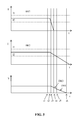
- Figure 4 shows the currents of the machinery brakes and the speed of the elevator car during a black-out or emergency stop according to a first example of the invention.
- the uppermost diagram represents the current in the first brake BR1
- the diagram in the middle represents the current in the second brake BR2
- the lowermost diagram represents the speed of the elevator car.
- the black-out or emergency stop occurs in the beginning of a drive sequence.
- the brake currents are at the pick-up level I1.
- the emergency stop operation is started when the main control system 500 of the elevator detects the need for an emergency stop and the brake control system 300 starts to release the machinery brake so that the machinery brake can close.
- the switch S5 feeds the intermediate circuit IC1 and it will typically open in the time interval between the point t1 and the point t3 in time preventing additional energy from flowing to the intermediate circuit IC1.
- the brake control system 300 starts to reduce the current of the first brake inductor L1 in the first brake BR1 at the point t2 in time by opening the switches S1 and S2.
- An alternative reverse directed current path from the first brake inductor L1 in the first brake BR1 to the capacitor C1 in the intermediate circuit IC1 is thereby opened through the diodes D1 and D2.
- the current of the first brake inductor L1 in the first brake BR1 drops below the hold current I2, which means that the first brake BR1 starts to brake i.e. produce a retarding torque.
- the speed of the elevator car will thus start to slow down according to the first decreasing slope DR1 in the lowermost diagram.
- the current of the first brake BR1 reaches the value zero at a point t4 in time.
- the energy stored in the first brake inductor L1 of the first brake BR1 will be discharged to the capacitor C1 in the intermediate circuit IC1 in the time interval between the point t2 and the point t4 in time.
- the current of the second brake BR2 is first kept above the hold current I2.
- the energy that has been discharged from the first brake inductor L1 into the capacitor C1 in the intermediate circuit IC1 can be used to control the second brake BR2. This can be done by controlling the drop of the current in the second brake inductor L2 in the second brake BR2 by the switches S3 and S4 in order to achieve a desired retarding brake torque.
- a slow drop of the current in the second brake inductor L2 can be achieved by keeping the switch S4 open so that the current flows through the diode D3 during the time when switch S3 is closed.
- a semi-slow drop of the current that flows in the second brake inductor L2 can be achieved e.g.
- Figure 5 shows the currents of the machinery brakes and the speed of the elevator car during a black-out or emergency stop according to a second example of the invention.
- the black-out or emergency stop occurs in the middle or at the end of a drive sequence so the brake currents are at the hold level I2.
- the brake control system 300 starts to decrease the current of the first brake inductor L1 in the first brake BR1 and the second brake inductor L2 in the second brake BR2 at the point t2 in time by opening the switches S1 and S2. At the point t3 in time the current of the first brake inductor L1 in the first brake BR1 decreases below the hold current I2, which means that the first brake BR1 starts to produce a retarding torque.
- the speed of the elevator car will thus start to slow down according to the third decreasing slope DR3 in the lowermost diagram.
- the current of the first brake BR1 reaches the value zero at the point t4 in time.
- the energy stored in the first brake inductor L1 of the first brake BR1 will be discharged to the capacitor C1 in the intermediate circuit IC1 during the interval between the point t2 and the point t4 in time.
- the energy that has been stored into the capacitor C1 of the intermediate circuit IC1 can be used to control the second brake BR2. This can be done by controlling the drop of the current in the second brake inductor L2 in the second brake BR2 by the switches S3 and S4 in order to achieve a desired retarding brake torque. At the point t5 in time the current in the second brake BR2 reaches the hold current I2 level, whereby the second brake BR starts to produce an additional retarding brake torque. The speed of the elevator car will thus start to slow down according to the fourth decreasing slope DR4 in the lowermost diagram.
- the first brake BR1 and the second brake BR2 can be controlled based on a previously identified drive situation and based on the driving speed of the elevator car at the moment when the emergency stop occurs or based on measured information of the retardation of the elevator car.
- diode means includes in this application these both alternatives and all other alternatives where an element restricting the current flow into only one direction is used.
- the brake control circuits BC1, BC2 are identical in the embodiment shown in figure 3 , but this is not necessary in the invention. Only one of the first brake control circuit BC1 and brake control circuit BC2 could be provided with the two current paths providing the possibility of coupling the brake inductor L1, L2 in a normal forward direction and in a reverse direction to the capacitor C1 in the intermediate circuit IC1. The other brake control circuit BC1, BC2 could be provided with only one current path so that coupling of the brake inductor L1, L2 only in the normal forward direction would be possible in said brake control circuit BC1, BC2.
- the use of the invention is naturally not limited to the type of elevator disclosed in the figures.
- the invention can be used in any type of elevator e.g. also in elevators lacking a machine room and/or a counterweight.
- the counter weight is in the figures positioned on the back wall of the elevator shaft.
- the counter weight could be positioned on either side wall of the elevator shaft or on both side walls of the elevator shaft.
- the lifting machinery is in the figures positioned at the top of the elevator shaft.
- the lifting machinery could be positioned at the bottom of the elevator shaft or at some point between the bottom and the top within the elevator shaft.
Landscapes
- Engineering & Computer Science (AREA)
- Automation & Control Theory (AREA)
- Elevator Control (AREA)
Abstract
Description
- The invention relates to a method and an arrangement for controlling an elevator machinery brake.
- An elevator comprises typically a car, an elevator shaft, a machine room, lifting machinery, ropes, and a counter weight. The elevator car is supported on a sling surrounding the car. The lifting machinery comprises a sheave, a machinery brake and an electric motor for rotating the sheave. The lifting machinery moves the car in a vertical direction upwards and downwards in the vertically extending elevator shaft. The sling and the car are carried by the ropes, which connect the car to the counter weight. The sling of the car is further supported with gliding means at guide rails extending in the vertical direction in the shaft. The gliding means can comprise rolls rolling on the guide rails or gliding shoes gliding on the guide rails when the elevator car is moving upwards and downwards in the elevator shaft. The guide rails are attached with fastening brackets at the side wall structures of the elevator shaft. The gliding means engaging with the guide rails keep the car in position in the horizontal plane when the car moves upwards and downwards in the elevator shaft. The counter weight is supported in a corresponding way on guide rails attached on the wall structure of the shaft. The car transports people and/or goods between the landings in the building. The elevator shaft can be formed so that the wall structure is formed of solid walls or so that the wall structure is formed of an open steel structure.
- Electromechanical drum brakes and disc brakes are typically used as machinery brakes in elevators. An electromechanical machinery brake comprises normally stationary brake shoes acting on a brake surface rotating with the sheave. The brake shoes are pressed against the brake surface by means of a mechanical force e.g. a spring and released from the brake surface by the force of an electromagnet. The electromagnet comprises one or several coils and an armature. The electromagnet can be energized with an electric current, whereby a magnetic field is produced in the electromagnet. The magnetic field will attract a counterpart of the armature. The counterpart of the armature moves in the opposite direction by a mechanical force when the electric current is disrupted. The brake shoes can be mechanically connected to the counterpart of the armature.
- The machinery brake will automatically be engaged i.e. the brake shoes will be pressed against the brake surface when the power supply to the coils of the machinery brake is for some reason disrupted. The power supply to the coils can be disrupted on purpose by opening a switch when the intention is to use the machinery brake to hold the elevator car at a desired landing. The power supply to the coils can, however, also be disrupted unintentionally due to a black-out in the power supply to the elevator. The machinery brake will thus be activated automatically stopping the movement of the elevator car when the black-out occurs.
- A machinery brake in an elevator comprises two electromechanical machinery brakes for safety reasons. This means that two brake coils are controlled by the elevator brake control circuit.
- The elevator car can in a black-out or emergency stop situation be stopped in two ways in prior art solutions. Both machinery brakes can be caused to brake rapidly. This means that the coils in the brakes should be deenergized rapidly. This can be done by connecting each coil to a circuit producing a high reverse voltage causing a rapid decrease of the current in the coil, whereby the mechanical force will cause the machinery brake to brake rapidly. The machinery brake can alternatively be caused to brake slowly by generating a low reverse voltage e.g. with a diode, whereby the current decreases slowly in the coil of the machinery brake.
- There are thus only two discrete possibilities to control the braking of the machinery brake in a black-out or emergency stop situation. There is thus a need to be able to control the braking of the machinery brake in a black out or emergency stop situation in order to achieve a smooth and controlled stop of the elevator car in the black out situation.
- The friction between the ropes and the traction sheave in an elevator provided with ropes is on a moderate level. This means that a rapid braking of the machinery brakes will not normally cause a too high retardation of the elevator car. There will be a small sliding between the ropes and the traction sheave smoothing the retardation of the elevator car.
- The friction between the belts and the traction sheave in an elevator provided with belts is on the other hand on a much higher level. This means that a rapid braking of the machinery brakes will cause a too high retardation of the elevator car. There is thus a need to be able to control the machinery brakes in a black-out or emergency braking situation in order to be able to make the retardation of the elevator car smoother.
- An object of the present invention is to present a novel method and a novel arrangement for controlling the braking of an elevator machinery brake.
- The method for controlling an elevator machinery brake is characterized by what is stated in the characterizing portion of
claim 1. - The arrangement for controlling an elevator machinery brake is characterized by what is stated in the characterizing portion of claim 6.
- The brake control system in the method for controlling an elevator machinery brake comprising two brakes comprises:
- a rectifier bridge comprising DC voltage output terminals,
- an intermediate circuit comprising a capacitor coupled in parallel to the DC voltage output terminals of the rectifier bridge,
- a first brake control circuit comprising input terminals and output terminals, the input terminals of the first brake control circuit being coupled to the DC voltage output terminals of the rectifier bridge, a first brake inductor in the first brake being coupled to the output terminals of the first brake control circuit,
- a second brake control circuit comprising input terminals and output terminals, the input terminals of the second brake control circuit being coupled to the DC voltage output terminals of the rectifier bridge, a second brake inductor in the second brake being coupled to output terminals of the second brake circuit.
- The method for controlling the elevator machinery brake comprising two brakes comprises:
- providing two current paths in at least one of the first brake control circuit and the second brake control circuit, whereby the brake inductor of the respective brake can be coupled to the capacitor in the intermediate circuit through a first, forward directed current path being provided for charging energy into the brake inductor, and a second, reverse directed current path being provided for discharging energy from the brake inductor,
- using the energy discharged from the brake inductor of the respective brake in the other brake control circuit in order to control the braking of the other brake to cause a controlled smooth stop of the elevator car.
- The brake control system in the arrangement for controlling an elevator machinery brake comprising two brakes comprises:
- a rectifier bridge comprising DC voltage output terminals,
- an intermediate circuit comprising a capacitor coupled to the DC voltage output terminals of the rectifier bridge,
- a first brake control circuit comprising input terminals and output terminals, the input terminals of the first brake control circuit being coupled to the DC voltage output terminals of the rectifier bridge, a first brake inductor in the first brake being coupled to the output terminals of the first brake control circuit,
- a second brake control circuit comprising input terminals and output terminals, the input terminals of the second brake control circuit being coupled to the DC voltage output terminals of the rectifier bridge, a second brake inductor in the second brake being coupled to output terminals of the second brake circuit.
- The arrangement for controlling the elevator machinery brake comprising two brakes is characterized in that:
- at least one of the first brake control circuit and the second brake control circuit comprises two current paths, whereby the brake inductor of the respective brake can be coupled to the capacitor in the intermediate circuit through a first, forward directed current path being provided for charging energy into the brake inductor, and a second, reverse directed current path being provided for discharging energy from the brake inductor.
- The method and the arrangement provides for a possibility to control the retardation of the elevator car in a black-out or emergency stop situation so that a smooth braking of the machinery brake and thereby a smooth retardation of the elevator car can be achieved.
- The invention will in the following be described in greater detail by means of preferred embodiments with reference to the attached drawings, in which
-
Figure 1 shows a vertical cross section of an elevator, -
Figure 2 shows a block diagram of the main parts in a control system of an elevator, -
Figure 3 shows an elevator machinery brake control system in which the invention can be applied, -
Figure 4 shows the currents of the machinery brakes and the speed of the elevator car during a black-out or emergency stop according to a first example of the invention, -
Figure 5 shows the currents of the machinery brakes and the speed of the elevator car during a black-out or emergency stop according to a second example of the invention. -
Fig. 1 shows a vertical cross section of an elevator. The elevator comprises acar 10, anelevator shaft 20, amachine room 30, liftingmachinery 40,ropes 41, and acounter weight 42. Thecar 10 is supported on asling 11 surrounding thecar 10. Thelifting machinery 40 comprises asheave 43, amachinery brake 100 and anelectric motor 44 for rotating thesheave 43 via ashaft 45. Thelifting machinery 40 moves thecar 10 in a vertical direction S1 upwards and downwards in the vertically extendingelevator shaft 20. Thesling 11 and thecar 10 within it are carried by theropes 41, which connect thecar 10 to thecounter weight 42. Thesling 11 of thecar 10 is further supported with gliding means 70 atguide rails 50 extending in the vertical direction in theshaft 20. The figure shows twoguide rails 50 at opposite sides of thecar 10. The gliding means 70 can comprise rolls rolling on the guide rails 50 or gliding shoes gliding on the guide rails 50 when thecar 10 is moving upwards and downwards in theelevator shaft 20. The guide rails 50 are attached with fish plates andfastening brackets 60 to theside wall structures 21 in theelevator shaft 20. The figure shows only twofastening brackets 60, but there areseveral fastening brackets 60 along the height of eachguide rail 50. The gliding means 70 engaging with the guide rails 50 keep thecar 10 in position in the horizontal plane when thecar 10 moves upwards and downwards in theelevator shaft 20. Thecounter weight 42 is supported in a corresponding way on guide rails attached on thewall structure 21 of theshaft 20. Thecar 10 transports people and/or goods between the landings in the building. Theelevator shaft 20 can be formed so that thewall structure 21 is formed of solid walls or so that thewall structure 21 is formed of an open steel structure. -
Figure 2 shows a block diagram of the main parts in a control system of an elevator. Theelevator car 10 is carried by theropes 41, which connect thecar 10 to thecounter weight 42. Theropes 41 pass over thesheave 43 shown infigure 1 . Thesheave 43 is driven by theelectric motor 44. The system comprises amachinery brake 100, a machinerybrake control system 300, afrequency converter 400, and amain control system 500. - The
frequency converter 400 is connected to theelectrical grid 200. Thefrequency converter 400 controls the rotation of theelectric motor 44. Theelectric motor 44 is advantageously a permanentmagnet synchronous motor 44. Thefrequency converter 400 controls the rotation of theelectric motor 44. The speed of rotation and the direction of rotation of the rotor of theelectric motor 44 are measured with asensor 600, which is connected to thefrequency converter 400. The sensor may be an encoder or a tachometer. Another possibility is to determine the movement of the rotor of theelectric motor 44 from the position of the permanent magnets with a Hall-sensor or from a voltage or current measurement by calculating from the counter voltage of theelectric motor 44. Thefrequency converter 400 also receives a rotational speed reference of theelectric motor 44 from themain control system 500. The rotational reference speed data of theelectric motor 44 is the target value of the rotational speed of theelectric motor 44. - The machinery
brake control system 300 is used to control theelectromagnetic machinery brake 100 of the elevator. The machinerybrake control system 300 can e.g. be situated in connection with the control panel of the elevator or in connection with themain control unit 500 or in the vicinity of themachinery brake 100. -
Figure 3 shows an elevator machinery brake control system. The machinerybrake control system 300 is formed of a rectifier bridge RB1, an intermediate circuit IC1, a first brake control circuit BC1 and a second brake control circuit BC2. The first brake control circuit BC1 controls the first brake inductor L1 in the first brake BR1. The second brake control circuit BC2 controls the second brake inductor L2 in the second brake BR2. Themachinery brake 100 comprises thus two brakes BR1, BR2 supplied by a common voltage source i.e. the rectifier bridge RB1. - AC electric power is provided from the
grid 200 to the input terminals P1, P2 of the rectifier bridge RB1. The rectifier bridge RB1 converts theAC grid 200 voltage at the input terminals P1, P2 of the rectifier bridge RB1 into a direct voltage U1 at the DC voltage output terminals P3, P4 of the rectifier bridge RB1. The first DC voltage output terminal P3 is the positive pole of the DC output voltage U1 and the second DC voltage output terminal P4 is the negative pole of the DC output voltage U1. - An intermediate circuit IC1 comprising a capacitor C1 is coupled in parallel to the DC voltage output terminals P3, P4 of the rectifier bridge RB1. The function of the capacitor C1 is to lessen the variation in (or to smooth) the rectified direct voltage U1 provided at the DC voltage output terminals P3, P4 of the rectifier bridge RB1.
- The direct voltage U1 provided at the DC voltage output terminals P3, P4 of the rectifier bridge RB1 and acting over the capacitor C1 in the intermediate circuit IC1 is then coupled to the input terminals P5, P6 of the first brake control circuit BC1 and to the input terminals P7, P8 of the second brake control circuit BC2. The first brake control circuit BC1 is coupled in parallel to the DC voltage output terminals P3, P4 of the rectifier bridge RB1 i.e. in parallel with the capacitor C1 of the intermediate circuit IC1. The second brake control circuit BC2 is coupled in parallel to the DC voltage output terminals P3, P4 of the rectifier bridge RB1 i.e. in parallel with the capacitor C1 of the intermediate circuit IC1. The first brake control circuit BC1 and the second brake control circuit BC2 are thus coupled in parallel to the DC voltage output terminals P3, P4 of the rectifier bridge RB1.
- The first inductor L1 in the first brake BR1 is coupled to the output terminals M1, M2 of the first brake control circuit BC1. The first brake control circuit BC1 comprises two different current paths i.e. a first, forward directed current path and a second, reverse directed current path.
- The first, forward directed current path passes from the first input terminal P5 of the first brake control circuit BC1 over a first switch S1 to the first output terminal M1 of the first brake control circuit BC1 and further through the first inductor L1 of the first brake BR1 to the second output terminal M2 of the first brake control circuit BC1 and further over a second switch S2 to the second input terminal P6 of the first brake control circuit BC1.
- The second, reverse directed current path passes from the second input terminal P6 of the first brake control circuit BC1 through a forward coupled second diode D2 to the first output terminal M1 of the first brake control circuit BC1 and further through the first inductor L1 of the first brake BR1 to the second output terminal M2 of the first brake control circuit BC1 and further through a forward coupled first diode D1 to the first input terminal P5 of the first brake control circuit BC1.
- The two current paths are formed by two parallel current circuits connected between the input terminals P5, P6 of the first brake control circuit BC1.
- The first current circuit comprises a series connection of the first diode D1 and the second switch S2. The cathode side of the first diode D1 is coupled to the first input terminal P5 of the first brake control circuit BC1 and the second side of the second switch S2 is coupled to the second input terminal P6 of the first brake control circuit BC1. The anode side of the first diode D1 is connected to the first side of the second switch S2.
- The second current circuit comprises a series connection of the first switch S1 and the second diode D2. The first side of the first switch S1 is coupled to the first input terminal P5 of the first brake control circuit BC1 and the anode side of the second diode D2 is coupled to the second input terminal P6 of the first brake control circuit BC1. The second side of the first switch S1 is connected to the cathode side of the second diode D2.
- The output terminals M1, M2 of the first brake control circuit BC1 are formed by the middle points M1, M2 of the first current circuit and the second current circuit. The middle point M1 of the first current circuit is located between the first diode D1 and the second switch S2. The middle point M2 of the second current circuit is located between the first switch S1 and the second diode D2.
- A first snubber RC1 is further coupled in parallel with the first brake inductor L1. The first snubber RC1 comprises in this embodiment a series connection of a diode and a varistor. A sudden interruption of the current flow to the first brake inductor L1 in the first brake BR1 will result in a high reverse voltage over the first brake inductor L1. The first snubber RC1 provides a short term alternative current path for the first brake inductor L1 to be discharged when the external current flow to the first brake inductor L1 is interrupted. The first snubber RC1 protects the capacitor C1 in the intermediate circuit IC1 and the first brake inductor L1 in the first brake BR1 by restricting over voltages produced in the first brake inductor L1 in the first brake BR1. The first snubber RC1 has as such no effect on the function of the invention.
- The second brake control circuit BC2 is identical with the first brake control circuit BC1.
- The second inductor L2 in the second brake BR2 is coupled to the output terminals M3, M4 of the second brake control circuit BC2. The second brake control circuit BC2 comprises two different current paths i.e. a first forward directed current path and a second reverse directed current path.
- The first, forward directed current path passes from the first input terminal P7 of the second brake control circuit BC2 over a first switch S3 to the first output terminal M3 of the second brake control circuit BC2 and further through the second inductor L2 of the second brake BR2 to the second output terminal M4 of the second brake control circuit BC2 and further over the second switch S4 to the second input terminal P8 of the second brake control circuit BC2.
- The second, reverse directed current path passes from the second input terminal P8 of the second brake control circuit BC2 through a forward coupled second diode D4 to the first output terminal M3 of the second brake control circuit BC2 and further through the second inductor L2 of the second brake BR2 to the second output terminal M4 of the second brake control circuit BC2 and further through a forward coupled second diode D3 to the first input terminal P7 of the second brake control circuit BC2.
- The two current paths are formed by two parallel current circuits connected between the input terminals P7, P8 of the second brake control circuit BC2.
- The first current circuit comprises a series connection of the first diode D3 and the second switch S4. The cathode side of the first diode D3 is coupled to the first input terminal P7 of the second brake control circuit BC2 and the second side of the second switch S4 is coupled to the second input terminal P8 of the second brake control circuit BC2. The anode side of the first diode D3 is connected to the first side of the second switch S4.
- The second current circuit comprises a series connection of the first switch S3 and the second diode D4. The first side of the first switch S3 is coupled to the first input terminal P7 of the second brake control circuit BC2 and the anode side of the second diode D4 is coupled to the second input terminal P8 of the second brake control circuit BC2. The second side of the first switch S3 is coupled to the cathode side of the second diode D4.
- The output terminals M3, M4 of the second brake control circuit BC2 are formed by the middle points M3, M4 of the first current circuit and the second current circuit. The middle point M3 of the first current circuit is located between the first diode D3 and the second switch S4. The middle point M2 of the second current circuit is located between the first switch S3 and the second diode D4.
- A second snubber RC2 is further coupled in parallel with the second brake inductor L2. The second snubber RC2 comprises in this embodiment a series connection of a diode and a varistor. A sudden interruption of the current flow to the second brake inductor L2 in the second brake BR2 will result in a high reverse voltage over the second brake inductor L2. The second snubber RC2 provides a short term alternative current path for the second brake inductor L2 to be discharged when the external current flow to the second brake inductor L2 is interrupted. The second snubber RC2 protects the capacitor C1 in the intermediate circuit IC1 and the second brake inductor L2 in the second brake BR2 by restricting over voltages produced in the second brake inductor L2 in the second brake BR2. The second snubber RC2 has as such no effect on the function of the invention.
- There is further a main switch S5 in the main voltage line before the input terminals P1, P2 of the rectifier bridge RB1. This is a part of the safety circuit of the elevator. The
main control system 500 will close the main switch S5 when themain control system 500 receives a control signal to move theelevator car 10 and all the prerequisites relating to safety issues are fulfilled. The main switch S5 is opened when there is a black-out. - The switches S1, S2, S3, S4 in the brake control circuits BC1, BC2 can be electromechanical switches e.g. relays or semiconductor switches e.g. mosfet or igbt switches.
- The
machinery brake system 300 opens the brakes BR1, BR2 by leading a pick-up current I1 to the brake inductors L1, L2 of the brakes BR1, BR2. The switches S1 and S2 in the first brake control circuit BC1 as well as the switches S3 and S4 in the second brake control circuit BC2 are closed in this situation. The pick-up current I1 is a current big enough to produce a magnetic force in the brake inductor L1, L2 that is able to open the brakes BR1, BR2. The current is then reduced to a lower level in order to save energy when the magnetic force required to open the brakes BR1, BR2 has been reached and the brakes BR1, BR2 are open. The lower level of the current is a hold current I2 that is able to keep the brakes BR1, BR2 open once they have been opened by the pick-up current I1. - When the switches S3, S4 in the second brake control circuit BC2 are closed, it is possible to control the braking of the second brake BR2 with the energy discharged from the first brake control circuit BC1 and the capacitor C1 in the intermediate circuit IC1. The start of the braking of the second brake BR2 can be delayed so that switches S3 and S4 are kept closed or by rounding out the start of the braking of the second brake BR2 by modulating the current energizing the second inductor L2 with switches S3 and/or S4. The other of the switches S3 and S4 can be closed and the other can be opened and closed in a desired sequence in order to modulate the current supplied to the second inductor L2.
-
Figure 4 shows the currents of the machinery brakes and the speed of the elevator car during a black-out or emergency stop according to a first example of the invention. The uppermost diagram represents the current in the first brake BR1, the diagram in the middle represents the current in the second brake BR2 and the lowermost diagram represents the speed of the elevator car. In this example the black-out or emergency stop occurs in the beginning of a drive sequence. Hence, the brake currents are at the pick-up level I1. - The emergency stop operation is started when the
main control system 500 of the elevator detects the need for an emergency stop and thebrake control system 300 starts to release the machinery brake so that the machinery brake can close. The switch S5 feeds the intermediate circuit IC1 and it will typically open in the time interval between the point t1 and the point t3 in time preventing additional energy from flowing to the intermediate circuit IC1. Thebrake control system 300 starts to reduce the current of the first brake inductor L1 in the first brake BR1 at the point t2 in time by opening the switches S1 and S2. An alternative reverse directed current path from the first brake inductor L1 in the first brake BR1 to the capacitor C1 in the intermediate circuit IC1 is thereby opened through the diodes D1 and D2. At the point t3 in time, the current of the first brake inductor L1 in the first brake BR1 drops below the hold current I2, which means that the first brake BR1 starts to brake i.e. produce a retarding torque. The speed of the elevator car will thus start to slow down according to the first decreasing slope DR1 in the lowermost diagram. The current of the first brake BR1 reaches the value zero at a point t4 in time. The energy stored in the first brake inductor L1 of the first brake BR1 will be discharged to the capacitor C1 in the intermediate circuit IC1 in the time interval between the point t2 and the point t4 in time. - The current of the second brake BR2 is first kept above the hold current I2. The energy that has been discharged from the first brake inductor L1 into the capacitor C1 in the intermediate circuit IC1 can be used to control the second brake BR2. This can be done by controlling the drop of the current in the second brake inductor L2 in the second brake BR2 by the switches S3 and S4 in order to achieve a desired retarding brake torque. A slow drop of the current in the second brake inductor L2 can be achieved by keeping the switch S4 open so that the current flows through the diode D3 during the time when switch S3 is closed. A semi-slow drop of the current that flows in the second brake inductor L2 can be achieved e.g. by keeping switch S3 closed and by switching switch S4 with pulse width modulation, whereby the time the switch S4 is closed determines the declining slope of the current. At the point t5 in time the current in the inductor L2 in the second brake BR2 reaches the hold current I2 level, whereby the second brake BR starts to produce an additional retarding brake torque. The speed of the elevator car will thus start to slow down according to the second decreasing slope DR2 in the lowermost diagram.
-
Figure 5 shows the currents of the machinery brakes and the speed of the elevator car during a black-out or emergency stop according to a second example of the invention. In this example the black-out or emergency stop occurs in the middle or at the end of a drive sequence so the brake currents are at the hold level I2. Thebrake control system 300 starts to decrease the current of the first brake inductor L1 in the first brake BR1 and the second brake inductor L2 in the second brake BR2 at the point t2 in time by opening the switches S1 and S2. At the point t3 in time the current of the first brake inductor L1 in the first brake BR1 decreases below the hold current I2, which means that the first brake BR1 starts to produce a retarding torque. The speed of the elevator car will thus start to slow down according to the third decreasing slope DR3 in the lowermost diagram. The current of the first brake BR1 reaches the value zero at the point t4 in time. The energy stored in the first brake inductor L1 of the first brake BR1 will be discharged to the capacitor C1 in the intermediate circuit IC1 during the interval between the point t2 and the point t4 in time. - The energy that has been stored into the capacitor C1 of the intermediate circuit IC1 can be used to control the second brake BR2. This can be done by controlling the drop of the current in the second brake inductor L2 in the second brake BR2 by the switches S3 and S4 in order to achieve a desired retarding brake torque. At the point t5 in time the current in the second brake BR2 reaches the hold current I2 level, whereby the second brake BR starts to produce an additional retarding brake torque. The speed of the elevator car will thus start to slow down according to the fourth decreasing slope DR4 in the lowermost diagram.
- The first brake BR1 and the second brake BR2 can be controlled based on a previously identified drive situation and based on the driving speed of the elevator car at the moment when the emergency stop occurs or based on measured information of the retardation of the elevator car.
- It is also possible to discharge the energy stored in the brake inductor L1, L2 of the brake BR1, BR2 simultaneously to the capacitor C1 in the intermediate circuit and to the brake inductor L1, L2 in the other brake BR1, BR2.
- The circuit shown in
figure 3 could be modified so that the diodes D1, D2, D3, D4 are replaced with switches having a parallel diode e.g. a n-channel mosfet. This solution is more expensive, but the advantage is that the direction of the current can also be reversed, which makes it possible to achieve a faster change of the current. The term diode means includes in this application these both alternatives and all other alternatives where an element restricting the current flow into only one direction is used. - The brake control circuits BC1, BC2 are identical in the embodiment shown in
figure 3 , but this is not necessary in the invention. Only one of the first brake control circuit BC1 and brake control circuit BC2 could be provided with the two current paths providing the possibility of coupling the brake inductor L1, L2 in a normal forward direction and in a reverse direction to the capacitor C1 in the intermediate circuit IC1. The other brake control circuit BC1, BC2 could be provided with only one current path so that coupling of the brake inductor L1, L2 only in the normal forward direction would be possible in said brake control circuit BC1, BC2. - The use of identical brake control circuits BC1, BC2 in both brakes BR1, B2 as shown in the embodiment in
figure 3 makes it possible to change the brake circuit BC1, BC2 that is used in the forward direction and in the reverse direction in order to maintain an even wearing of the brake components in both brakes BR1, BR2. - The use of the invention is naturally not limited to the type of elevator disclosed in the figures. The invention can be used in any type of elevator e.g. also in elevators lacking a machine room and/or a counterweight. The counter weight is in the figures positioned on the back wall of the elevator shaft. The counter weight could be positioned on either side wall of the elevator shaft or on both side walls of the elevator shaft. The lifting machinery is in the figures positioned at the top of the elevator shaft. The lifting machinery could be positioned at the bottom of the elevator shaft or at some point between the bottom and the top within the elevator shaft.
- It will be obvious to a person skilled in the art that, as the technology advances, the inventive concept can be implemented in various ways. The invention and its embodiments are not limited to the examples described above but may vary within the scope of the claims.
Claims (12)
- A method for controlling an elevator machinery brake comprising two brakes (BR1, BR2) being controlled by a brake control system (300) comprising:a rectifier bridge (RB1) comprising DC voltage output terminals (P3, P4),an intermediate circuit (IC1) comprising a capacitor (C1) coupled in parallel to the DC voltage output terminals (P3, P4) of the rectifier bridge (RB1),a first brake control circuit (BC1) comprising input terminals (P5, P6) and output terminals (M1, M2), the input terminals (P5, P6) of the first brake control circuit (BC1) being coupled to the output terminals (P3, P4) of the rectifier bridge (RB1), a first brake inductor (L1) in the first brake (BR1) being coupled to the output terminals (M1, M2) of the first brake control circuit (BC1),a second brake control circuit (BC2) comprising input terminals (P7, P8) and output terminals (M3, M4), the input terminals (P7, P8) of the second brake control circuit (BC2) being coupled to the output terminals (P3, P4) of the rectifier bridge (RB1), a second brake inductor (L2) in the second brake (BR2) being coupled to output terminals (M3, M4) of the second brake circuit (BC2),the method comprising:providing two current paths (P5-S1-M1-L1-M2-S2-P6, P6-D2-M1-L1-M2-D1-P5) and (P7-S3-M3-L2-M4-S4-P8, P8-D4-M3-L2-M4-D3-P7) in at least one of the first brake control circuit (BC1) and the second brake control circuit (BC2), whereby the brake inductor (L1, L2) of the respective brake (B1, B2) can be coupled to the capacitor (C1) in the intermediate circuit (IC1) through a first, forward directed current path being provided for charging energy into the brake inductor (L1, L2), and a second, reverse directed current path being provided for discharging energy from the brake inductor (L1, L2),using the energy discharged from the brake inductor (L1, L2) of the respective brake (BR1, BR2) in the other brake control circuit (BC1, BC2) in order to control the braking of the other brake (BR1, BR2) to cause a controlled smooth stop of the elevator car (10).
- A method according to claim 1, further characterized by:connecting the brake inductor (L1, L2) through the first current path in the forward direction through a first switch (S1, S3) to a first input terminal (P5, P7) in the respective brake control circuit (BC1, BC2) and through a second switch (S2, S4) to a second input terminal (P6, P8) of the respective brake control circuit (BC1, BC2),connecting the brake inductor (L1, L2) through the second current path in the reverse direction through a second diode means (D2, D4) to the second input terminal (P6, P8) of the respective brake control circuit (BC1, BC2) and through a first diode means (D1, D3) to the first input terminal (P5, P7) of the respective brake control circuit (BC1, BC2).
- A method according to claim 1 or 2, further characterized by:providing two parallel connected current circuits between the input terminals (P5, P6) of the respective brake control circuit (BC1, BC2),each of the current circuits comprising a series connection of a switch (S1, S2, S3, S4) and a diode means (D1, D2, D3, D4),the output terminals (M1, M2) of the respective brake control circuit (BC1, BC2) being formed in each of the current circuits between the switch (S1, S2, S3, S4) and the diode means (D1, D2, D3, D4),the first forward directed current path being formed from the first input terminal (P5) to the second input terminal (P6) of the respective brake control circuit (BC1, BC2) through the first switch (S1, S3) in a first of the current circuits and further through the inductor (L1, L2) and further through the second switch (S2, S4) in a second of the current circuits,the second reverse directed current path being formed from the second input terminal (P6) to the first input terminal (P5) of the respective brake control circuit (BC1, BC2) through a second diode means (D2, D4) in the first of the current circuits and further through the inductor (L1, L2) and further through a first diode means (D1, D3) in the second of the current circuits.
- A method according to any one of claims 1 to 3 further characterized by:connecting the brake inductor (L1, L2) of a first brake (BR1, BR2) to the intermediate circuit (IC1) so that the energy stored in the brake inductor (L1, L2) of the first brake (BR1, BR2) is discharged into the capacitor (C1) of the intermediate circuit (IC1), whereby the current in the brake inductor (L1, L2) of the first brake (BR1, BR2) drops rapidly and the first brake (BR1, BR2) starts to produce a retarding torque when the current in the brake inductor (L1, L2) of the first brake (BR1, BR2) drops below a hold current (I2) level,using the energy discharged from the brake inductor (L1, L2) of the first brake (BR1, BR2) in order to control the current of the brake inductor (L1, L2) of a second brake (BR1, BR2) to drop along a predefined downward sloping ramp, whereby the retarding torque of the second brake (BR1, BR2) increases in a corresponding way causing a controlled smooth stop of the elevator car (10).
- A method according to any one of claims 1 to 4 further characterized by protecting the brake inductor (L1, L2) and the capacitor (C1) in the intermediate circuit (IC1) by connecting a snubber (RC1, RC2) in parallel with the brake inductor (L1, L2).
- An arrangement for controlling an elevator machinery brake comprising two brakes (BR1, BR2) being controlled by a brake control system (300) comprising:a rectifier bridge (RB1) comprising DV voltage output terminals (P3, P4),an intermediate circuit (IC1) comprising a capacitor (C1) coupled to the DC voltage output terminals (P3, P4) of the rectifier bridge (RB1),a first brake control circuit (BC1) comprising input terminals (P5, P6) and output terminals (M1, M2), the input terminals (P5, P6) of the first brake control circuit (BC1) being coupled to the DC voltage output terminals (P3, P4) of the rectifier bridge (RB1), a first brake inductor (L1) in the first brake (BR1) being coupled to the output terminals (M1, M2) of the first brake control circuit (BC1),a second brake control circuit (BC2) comprising input terminals (P7, P8) and output terminals (M3, M4), the input terminals (P7, P8) of the second brake control circuit (BC2) being coupled to the DC voltage output terminals (P3, P4) of the rectifier bridge (RB1), a second brake inductor (L2) in the second brake (BR2) being coupled to output terminals (M3, M4) of the second brake circuit (BC2),characterized in that:at least one of the first brake control circuit (BC1) and the second brake control circuit (BC2) comprises two current paths (P5-S1-M1-L1-M2-S2-P6, P6-D2-M1-L1-M2-D1-P5) and (P7-S3-M3-L2-M4-S4-P8, P8-D4-M3-L2-M4-D3-P7), whereby the brake inductor (L1, L2) of the respective brake (B1, B2) can be coupled to the capacitor (C1) in the intermediate circuit (IC1) through a first, forward directed current path being provided for charging energy into the brake inductor (L1, L2), and a second, reverse directed current path being provided for discharging energy from the brake inductor (L1, L2).
- An arrangement according to claim 6, characterized in that:the first current path connects the brake inductor (L1, L2) in the forward direction through a first switch (S1, S3) to a first input terminal (P5, P7) in the respective brake control circuit (BC1, BC2) and through a second switch (S2, S4) to a second input terminal (P6, P8) of the respective brake control circuit (BC1, BC2),the second current path connects the brake inductor (L1, L2) in the reverse direction through a second diode means (D2, D4) to the second input terminal (P6, P8) of the respective brake control circuit (BC1, BC2) and through a first diode means (D1, D3) to the first input terminal (P5, P7) of the respective brake control circuit (BC1, BC2).
- An arrangement according to claim 6 or 7, characterized in that:two parallel connected current circuits are provided between the input terminals (P5, P6) of the respective brake control circuit (BC1, BC2),each of the current circuits comprising a series connection of a switch (S1, S2, S3, S4) and a diode means (D1, D2, D3, D4),the output terminals (M1, M2) of the respective brake control circuit (BC1, BC2) being formed in each of the current circuits between the switch (S1, S2, S3, S4) and the diode means (D1, D2, D3, D4),the first forward directed current path being formed from the first input terminal (P5) to the second input terminal (P6) of the respective brake control circuit (BC1, BC2) through the first switch (S1, S3) in a first of the current circuits and further through the inductor (L1, L2) and further through the second switch (S2, S4) in a second of the current circuits,the second reverse directed current path being formed from the second input terminal (P6) to the first input terminal (P5) of the respective brake control circuit (BC1, BC2) through a second diode means (D2, D4) in the first of the current circuits and further through the inductor (L1, L2) and further through a first diode means (D1, D3) in the second of the current circuits.
- An arrangement according to claim 7, characterized in that the first diode means (D1, D3) and the second diode means (D2, D4) are formed by diodes (D1, D2, D3, D4).
- An arrangement according to claim 7, characterized in that the first diode means (D1, D3) and the second diode means (D2, D4) are formed by a switch and a diode (D1, D2, D3, D4) coupled in parallel.
- An arrangement according to any one of claims 6 to 10, characterized in that the first brake control circuit (BC1) and the second brake control circuit (BC2) are identical.
- An arrangement according to any one of claim 6 to 10, characterized in that a snubber (RC1, RC2) is coupled in parallel with the brake inductor (L1, L2), said snubber (RC1, RC2) being used to protect the brake inductor (L1, L2) and the capacitor (C1) in the intermediate circuit (IC1).
Priority Applications (1)
| Application Number | Priority Date | Filing Date | Title |
|---|---|---|---|
| EP15188881.5A EP3153443B1 (en) | 2015-10-08 | 2015-10-08 | A method and an arrangement for controlling an elevator machinery brake |
Applications Claiming Priority (1)
| Application Number | Priority Date | Filing Date | Title |
|---|---|---|---|
| EP15188881.5A EP3153443B1 (en) | 2015-10-08 | 2015-10-08 | A method and an arrangement for controlling an elevator machinery brake |
Publications (2)
| Publication Number | Publication Date |
|---|---|
| EP3153443A1 true EP3153443A1 (en) | 2017-04-12 |
| EP3153443B1 EP3153443B1 (en) | 2021-09-08 |
Family
ID=54288703
Family Applications (1)
| Application Number | Title | Priority Date | Filing Date |
|---|---|---|---|
| EP15188881.5A Active EP3153443B1 (en) | 2015-10-08 | 2015-10-08 | A method and an arrangement for controlling an elevator machinery brake |
Country Status (1)
| Country | Link |
|---|---|
| EP (1) | EP3153443B1 (en) |
Cited By (1)
| Publication number | Priority date | Publication date | Assignee | Title |
|---|---|---|---|---|
| CN114835048A (en) * | 2022-04-07 | 2022-08-02 | 通力电梯有限公司 | Control device for elevator |
Citations (6)
| Publication number | Priority date | Publication date | Assignee | Title |
|---|---|---|---|---|
| JP2003292257A (en) * | 2002-04-04 | 2003-10-15 | Mitsubishi Electric Corp | Elevator brake drive |
| EP2028150A1 (en) * | 2006-06-15 | 2009-02-25 | Mitsubishi Electric Corporation | Brake system of elevator |
| WO2010100316A1 (en) * | 2009-03-05 | 2010-09-10 | Kone Corporation | Elevator system |
| WO2012052600A1 (en) * | 2010-10-21 | 2012-04-26 | Kone Corporation | Braking apparatus |
| WO2012105986A1 (en) * | 2011-02-04 | 2012-08-09 | Otis Elevator Company | Stop sequencing for braking device |
| JP2012218880A (en) * | 2011-04-08 | 2012-11-12 | Mitsubishi Electric Corp | Brake controller of elevator |
-
2015
- 2015-10-08 EP EP15188881.5A patent/EP3153443B1/en active Active
Patent Citations (6)
| Publication number | Priority date | Publication date | Assignee | Title |
|---|---|---|---|---|
| JP2003292257A (en) * | 2002-04-04 | 2003-10-15 | Mitsubishi Electric Corp | Elevator brake drive |
| EP2028150A1 (en) * | 2006-06-15 | 2009-02-25 | Mitsubishi Electric Corporation | Brake system of elevator |
| WO2010100316A1 (en) * | 2009-03-05 | 2010-09-10 | Kone Corporation | Elevator system |
| WO2012052600A1 (en) * | 2010-10-21 | 2012-04-26 | Kone Corporation | Braking apparatus |
| WO2012105986A1 (en) * | 2011-02-04 | 2012-08-09 | Otis Elevator Company | Stop sequencing for braking device |
| JP2012218880A (en) * | 2011-04-08 | 2012-11-12 | Mitsubishi Electric Corp | Brake controller of elevator |
Cited By (1)
| Publication number | Priority date | Publication date | Assignee | Title |
|---|---|---|---|---|
| CN114835048A (en) * | 2022-04-07 | 2022-08-02 | 通力电梯有限公司 | Control device for elevator |
Also Published As
| Publication number | Publication date |
|---|---|
| EP3153443B1 (en) | 2021-09-08 |
Similar Documents
| Publication | Publication Date | Title |
|---|---|---|
| JP6446512B2 (en) | Brake controller and elevator system | |
| CN108946369B (en) | Method for performing manual driving in elevator after main power supply is turned off | |
| US11097922B2 (en) | Current cut-off arrangement of an elevator | |
| JP5543454B2 (en) | Emergency mode operation method of elevator | |
| KR101229002B1 (en) | Safe control of a brake using low power control devices | |
| EP2174411B1 (en) | Electric motor drive | |
| KR100913337B1 (en) | Elevator control apparatus | |
| US10106373B2 (en) | Elevator brake controller for modulating DC voltage | |
| US11192752B2 (en) | Elevator drive control during power disruption | |
| US20130313052A1 (en) | Stop Sequencing for Braking Device | |
| US9120644B2 (en) | Braking device | |
| WO2013050660A1 (en) | Elevator monitoring arrangement and method for monitoring an elevator | |
| EP3153443B1 (en) | A method and an arrangement for controlling an elevator machinery brake | |
| JPH04286587A (en) | Linear motor type elevator control device | |
| JP2526732B2 (en) | Elevator control device | |
| EP3153448A1 (en) | Arrangement and method for controlling a machinery brake in an elevator | |
| HK1207355B (en) | Brake controller, elevator system and a method for performing an emergency stop with an elevator hoisting machine driven with a frequency converter | |
| HK40000778A (en) | Method for performing a manual drive in an elevator after mains power-off | |
| HK1223899B (en) | A brake controller and an elevator system | |
| HK1157722B (en) | Safe control of a brake using low power control devices |
Legal Events
| Date | Code | Title | Description |
|---|---|---|---|
| PUAI | Public reference made under article 153(3) epc to a published international application that has entered the european phase |
Free format text: ORIGINAL CODE: 0009012 |
|
| STAA | Information on the status of an ep patent application or granted ep patent |
Free format text: STATUS: THE APPLICATION HAS BEEN PUBLISHED |
|
| AK | Designated contracting states |
Kind code of ref document: A1 Designated state(s): AL AT BE BG CH CY CZ DE DK EE ES FI FR GB GR HR HU IE IS IT LI LT LU LV MC MK MT NL NO PL PT RO RS SE SI SK SM TR |
|
| AX | Request for extension of the european patent |
Extension state: BA ME |
|
| STAA | Information on the status of an ep patent application or granted ep patent |
Free format text: STATUS: REQUEST FOR EXAMINATION WAS MADE |
|
| 17P | Request for examination filed |
Effective date: 20170919 |
|
| RBV | Designated contracting states (corrected) |
Designated state(s): AL AT BE BG CH CY CZ DE DK EE ES FI FR GB GR HR HU IE IS IT LI LT LU LV MC MK MT NL NO PL PT RO RS SE SI SK SM TR |
|
| STAA | Information on the status of an ep patent application or granted ep patent |
Free format text: STATUS: EXAMINATION IS IN PROGRESS |
|
| 17Q | First examination report despatched |
Effective date: 20200102 |
|
| GRAP | Despatch of communication of intention to grant a patent |
Free format text: ORIGINAL CODE: EPIDOSNIGR1 |
|
| STAA | Information on the status of an ep patent application or granted ep patent |
Free format text: STATUS: GRANT OF PATENT IS INTENDED |
|
| INTG | Intention to grant announced |
Effective date: 20210330 |
|
| RAP3 | Party data changed (applicant data changed or rights of an application transferred) |
Owner name: KONE CORPORATION |
|
| GRAS | Grant fee paid |
Free format text: ORIGINAL CODE: EPIDOSNIGR3 |
|
| GRAA | (expected) grant |
Free format text: ORIGINAL CODE: 0009210 |
|
| STAA | Information on the status of an ep patent application or granted ep patent |
Free format text: STATUS: THE PATENT HAS BEEN GRANTED |
|
| AK | Designated contracting states |
Kind code of ref document: B1 Designated state(s): AL AT BE BG CH CY CZ DE DK EE ES FI FR GB GR HR HU IE IS IT LI LT LU LV MC MK MT NL NO PL PT RO RS SE SI SK SM TR |
|
| REG | Reference to a national code |
Ref country code: GB Ref legal event code: FG4D |
|
| REG | Reference to a national code |
Ref country code: AT Ref legal event code: REF Ref document number: 1428426 Country of ref document: AT Kind code of ref document: T Effective date: 20210915 Ref country code: CH Ref legal event code: EP |
|
| REG | Reference to a national code |
Ref country code: IE Ref legal event code: FG4D |
|
| REG | Reference to a national code |
Ref country code: DE Ref legal event code: R096 Ref document number: 602015073053 Country of ref document: DE |
|
| REG | Reference to a national code |
Ref country code: LT Ref legal event code: MG9D |
|
| REG | Reference to a national code |
Ref country code: NL Ref legal event code: MP Effective date: 20210908 |
|
| PG25 | Lapsed in a contracting state [announced via postgrant information from national office to epo] |
Ref country code: HR Free format text: LAPSE BECAUSE OF FAILURE TO SUBMIT A TRANSLATION OF THE DESCRIPTION OR TO PAY THE FEE WITHIN THE PRESCRIBED TIME-LIMIT Effective date: 20210908 Ref country code: RS Free format text: LAPSE BECAUSE OF FAILURE TO SUBMIT A TRANSLATION OF THE DESCRIPTION OR TO PAY THE FEE WITHIN THE PRESCRIBED TIME-LIMIT Effective date: 20210908 Ref country code: SE Free format text: LAPSE BECAUSE OF FAILURE TO SUBMIT A TRANSLATION OF THE DESCRIPTION OR TO PAY THE FEE WITHIN THE PRESCRIBED TIME-LIMIT Effective date: 20210908 Ref country code: LT Free format text: LAPSE BECAUSE OF FAILURE TO SUBMIT A TRANSLATION OF THE DESCRIPTION OR TO PAY THE FEE WITHIN THE PRESCRIBED TIME-LIMIT Effective date: 20210908 Ref country code: BG Free format text: LAPSE BECAUSE OF FAILURE TO SUBMIT A TRANSLATION OF THE DESCRIPTION OR TO PAY THE FEE WITHIN THE PRESCRIBED TIME-LIMIT Effective date: 20211208 Ref country code: NO Free format text: LAPSE BECAUSE OF FAILURE TO SUBMIT A TRANSLATION OF THE DESCRIPTION OR TO PAY THE FEE WITHIN THE PRESCRIBED TIME-LIMIT Effective date: 20211208 Ref country code: ES Free format text: LAPSE BECAUSE OF FAILURE TO SUBMIT A TRANSLATION OF THE DESCRIPTION OR TO PAY THE FEE WITHIN THE PRESCRIBED TIME-LIMIT Effective date: 20210908 Ref country code: FI Free format text: LAPSE BECAUSE OF FAILURE TO SUBMIT A TRANSLATION OF THE DESCRIPTION OR TO PAY THE FEE WITHIN THE PRESCRIBED TIME-LIMIT Effective date: 20210908 |
|
| REG | Reference to a national code |
Ref country code: AT Ref legal event code: MK05 Ref document number: 1428426 Country of ref document: AT Kind code of ref document: T Effective date: 20210908 |
|
| PG25 | Lapsed in a contracting state [announced via postgrant information from national office to epo] |
Ref country code: LV Free format text: LAPSE BECAUSE OF FAILURE TO SUBMIT A TRANSLATION OF THE DESCRIPTION OR TO PAY THE FEE WITHIN THE PRESCRIBED TIME-LIMIT Effective date: 20210908 Ref country code: GR Free format text: LAPSE BECAUSE OF FAILURE TO SUBMIT A TRANSLATION OF THE DESCRIPTION OR TO PAY THE FEE WITHIN THE PRESCRIBED TIME-LIMIT Effective date: 20211209 |
|
| PG25 | Lapsed in a contracting state [announced via postgrant information from national office to epo] |
Ref country code: AT Free format text: LAPSE BECAUSE OF FAILURE TO SUBMIT A TRANSLATION OF THE DESCRIPTION OR TO PAY THE FEE WITHIN THE PRESCRIBED TIME-LIMIT Effective date: 20210908 |
|
| REG | Reference to a national code |
Ref country code: CH Ref legal event code: PL |
|
| PG25 | Lapsed in a contracting state [announced via postgrant information from national office to epo] |
Ref country code: IS Free format text: LAPSE BECAUSE OF FAILURE TO SUBMIT A TRANSLATION OF THE DESCRIPTION OR TO PAY THE FEE WITHIN THE PRESCRIBED TIME-LIMIT Effective date: 20220108 Ref country code: SM Free format text: LAPSE BECAUSE OF FAILURE TO SUBMIT A TRANSLATION OF THE DESCRIPTION OR TO PAY THE FEE WITHIN THE PRESCRIBED TIME-LIMIT Effective date: 20210908 Ref country code: SK Free format text: LAPSE BECAUSE OF FAILURE TO SUBMIT A TRANSLATION OF THE DESCRIPTION OR TO PAY THE FEE WITHIN THE PRESCRIBED TIME-LIMIT Effective date: 20210908 Ref country code: RO Free format text: LAPSE BECAUSE OF FAILURE TO SUBMIT A TRANSLATION OF THE DESCRIPTION OR TO PAY THE FEE WITHIN THE PRESCRIBED TIME-LIMIT Effective date: 20210908 Ref country code: PT Free format text: LAPSE BECAUSE OF FAILURE TO SUBMIT A TRANSLATION OF THE DESCRIPTION OR TO PAY THE FEE WITHIN THE PRESCRIBED TIME-LIMIT Effective date: 20220110 Ref country code: PL Free format text: LAPSE BECAUSE OF FAILURE TO SUBMIT A TRANSLATION OF THE DESCRIPTION OR TO PAY THE FEE WITHIN THE PRESCRIBED TIME-LIMIT Effective date: 20210908 Ref country code: NL Free format text: LAPSE BECAUSE OF FAILURE TO SUBMIT A TRANSLATION OF THE DESCRIPTION OR TO PAY THE FEE WITHIN THE PRESCRIBED TIME-LIMIT Effective date: 20210908 Ref country code: EE Free format text: LAPSE BECAUSE OF FAILURE TO SUBMIT A TRANSLATION OF THE DESCRIPTION OR TO PAY THE FEE WITHIN THE PRESCRIBED TIME-LIMIT Effective date: 20210908 Ref country code: CZ Free format text: LAPSE BECAUSE OF FAILURE TO SUBMIT A TRANSLATION OF THE DESCRIPTION OR TO PAY THE FEE WITHIN THE PRESCRIBED TIME-LIMIT Effective date: 20210908 Ref country code: AL Free format text: LAPSE BECAUSE OF FAILURE TO SUBMIT A TRANSLATION OF THE DESCRIPTION OR TO PAY THE FEE WITHIN THE PRESCRIBED TIME-LIMIT Effective date: 20210908 |
|
| REG | Reference to a national code |
Ref country code: DE Ref legal event code: R097 Ref document number: 602015073053 Country of ref document: DE |
|
| REG | Reference to a national code |
Ref country code: BE Ref legal event code: MM Effective date: 20211031 |
|
| PG25 | Lapsed in a contracting state [announced via postgrant information from national office to epo] |
Ref country code: MC Free format text: LAPSE BECAUSE OF FAILURE TO SUBMIT A TRANSLATION OF THE DESCRIPTION OR TO PAY THE FEE WITHIN THE PRESCRIBED TIME-LIMIT Effective date: 20210908 |
|
| PLBE | No opposition filed within time limit |
Free format text: ORIGINAL CODE: 0009261 |
|
| STAA | Information on the status of an ep patent application or granted ep patent |
Free format text: STATUS: NO OPPOSITION FILED WITHIN TIME LIMIT |
|
| PG25 | Lapsed in a contracting state [announced via postgrant information from national office to epo] |
Ref country code: LU Free format text: LAPSE BECAUSE OF NON-PAYMENT OF DUE FEES Effective date: 20211008 Ref country code: DK Free format text: LAPSE BECAUSE OF FAILURE TO SUBMIT A TRANSLATION OF THE DESCRIPTION OR TO PAY THE FEE WITHIN THE PRESCRIBED TIME-LIMIT Effective date: 20210908 Ref country code: BE Free format text: LAPSE BECAUSE OF NON-PAYMENT OF DUE FEES Effective date: 20211031 |
|
| 26N | No opposition filed |
Effective date: 20220609 |
|
| PG25 | Lapsed in a contracting state [announced via postgrant information from national office to epo] |
Ref country code: SI Free format text: LAPSE BECAUSE OF FAILURE TO SUBMIT A TRANSLATION OF THE DESCRIPTION OR TO PAY THE FEE WITHIN THE PRESCRIBED TIME-LIMIT Effective date: 20210908 Ref country code: LI Free format text: LAPSE BECAUSE OF NON-PAYMENT OF DUE FEES Effective date: 20211031 Ref country code: CH Free format text: LAPSE BECAUSE OF NON-PAYMENT OF DUE FEES Effective date: 20211031 |
|
| PG25 | Lapsed in a contracting state [announced via postgrant information from national office to epo] |
Ref country code: IE Free format text: LAPSE BECAUSE OF NON-PAYMENT OF DUE FEES Effective date: 20211008 |
|
| PG25 | Lapsed in a contracting state [announced via postgrant information from national office to epo] |
Ref country code: IT Free format text: LAPSE BECAUSE OF FAILURE TO SUBMIT A TRANSLATION OF THE DESCRIPTION OR TO PAY THE FEE WITHIN THE PRESCRIBED TIME-LIMIT Effective date: 20210908 |
|
| PG25 | Lapsed in a contracting state [announced via postgrant information from national office to epo] |
Ref country code: HU Free format text: LAPSE BECAUSE OF FAILURE TO SUBMIT A TRANSLATION OF THE DESCRIPTION OR TO PAY THE FEE WITHIN THE PRESCRIBED TIME-LIMIT; INVALID AB INITIO Effective date: 20151008 |
|
| PG25 | Lapsed in a contracting state [announced via postgrant information from national office to epo] |
Ref country code: CY Free format text: LAPSE BECAUSE OF FAILURE TO SUBMIT A TRANSLATION OF THE DESCRIPTION OR TO PAY THE FEE WITHIN THE PRESCRIBED TIME-LIMIT Effective date: 20210908 |
|
| P01 | Opt-out of the competence of the unified patent court (upc) registered |
Effective date: 20230525 |
|
| PG25 | Lapsed in a contracting state [announced via postgrant information from national office to epo] |
Ref country code: MK Free format text: LAPSE BECAUSE OF FAILURE TO SUBMIT A TRANSLATION OF THE DESCRIPTION OR TO PAY THE FEE WITHIN THE PRESCRIBED TIME-LIMIT Effective date: 20210908 |
|
| PG25 | Lapsed in a contracting state [announced via postgrant information from national office to epo] |
Ref country code: MT Free format text: LAPSE BECAUSE OF FAILURE TO SUBMIT A TRANSLATION OF THE DESCRIPTION OR TO PAY THE FEE WITHIN THE PRESCRIBED TIME-LIMIT Effective date: 20210908 |
|
| REG | Reference to a national code |
Ref country code: DE Ref legal event code: R082 Ref document number: 602015073053 Country of ref document: DE Representative=s name: WUESTHOFF & WUESTHOFF PATENTANWAELTE UND RECHT, DE |
|
| PG25 | Lapsed in a contracting state [announced via postgrant information from national office to epo] |
Ref country code: TR Free format text: LAPSE BECAUSE OF FAILURE TO SUBMIT A TRANSLATION OF THE DESCRIPTION OR TO PAY THE FEE WITHIN THE PRESCRIBED TIME-LIMIT Effective date: 20210908 |
|
| PGFP | Annual fee paid to national office [announced via postgrant information from national office to epo] |
Ref country code: DE Payment date: 20251021 Year of fee payment: 11 |
|
| PGFP | Annual fee paid to national office [announced via postgrant information from national office to epo] |
Ref country code: GB Payment date: 20251022 Year of fee payment: 11 |
|
| PGFP | Annual fee paid to national office [announced via postgrant information from national office to epo] |
Ref country code: FR Payment date: 20251030 Year of fee payment: 11 |