EP3153402B1 - A heated floor panel system for an aircraft - Google Patents
A heated floor panel system for an aircraft Download PDFInfo
- Publication number
- EP3153402B1 EP3153402B1 EP15189160.3A EP15189160A EP3153402B1 EP 3153402 B1 EP3153402 B1 EP 3153402B1 EP 15189160 A EP15189160 A EP 15189160A EP 3153402 B1 EP3153402 B1 EP 3153402B1
- Authority
- EP
- European Patent Office
- Prior art keywords
- floor panel
- connector
- power
- link
- data
- Prior art date
- Legal status (The legal status is an assumption and is not a legal conclusion. Google has not performed a legal analysis and makes no representation as to the accuracy of the status listed.)
- Active
Links
- 239000002470 thermal conductor Substances 0.000 claims description 24
- 239000004020 conductor Substances 0.000 claims description 13
- 238000001514 detection method Methods 0.000 claims description 11
- 238000010438 heat treatment Methods 0.000 claims description 2
- 238000010276 construction Methods 0.000 description 3
- 238000010586 diagram Methods 0.000 description 3
- 230000007547 defect Effects 0.000 description 2
- 238000012423 maintenance Methods 0.000 description 2
- RYGMFSIKBFXOCR-UHFFFAOYSA-N Copper Chemical compound [Cu] RYGMFSIKBFXOCR-UHFFFAOYSA-N 0.000 description 1
- 229910052802 copper Inorganic materials 0.000 description 1
- 239000010949 copper Substances 0.000 description 1
- 239000002184 metal Substances 0.000 description 1
- 229910052751 metal Inorganic materials 0.000 description 1
Images
Classifications
-
- F—MECHANICAL ENGINEERING; LIGHTING; HEATING; WEAPONS; BLASTING
- F24—HEATING; RANGES; VENTILATING
- F24D—DOMESTIC- OR SPACE-HEATING SYSTEMS, e.g. CENTRAL HEATING SYSTEMS; DOMESTIC HOT-WATER SUPPLY SYSTEMS; ELEMENTS OR COMPONENTS THEREFOR
- F24D13/00—Electric heating systems
- F24D13/02—Electric heating systems solely using resistance heating, e.g. underfloor heating
- F24D13/022—Electric heating systems solely using resistance heating, e.g. underfloor heating resistances incorporated in construction elements
- F24D13/024—Electric heating systems solely using resistance heating, e.g. underfloor heating resistances incorporated in construction elements in walls, floors, ceilings
-
- H—ELECTRICITY
- H05—ELECTRIC TECHNIQUES NOT OTHERWISE PROVIDED FOR
- H05B—ELECTRIC HEATING; ELECTRIC LIGHT SOURCES NOT OTHERWISE PROVIDED FOR; CIRCUIT ARRANGEMENTS FOR ELECTRIC LIGHT SOURCES, IN GENERAL
- H05B1/00—Details of electric heating devices
- H05B1/02—Automatic switching arrangements specially adapted to apparatus ; Control of heating devices
- H05B1/0227—Applications
- H05B1/023—Industrial applications
- H05B1/0236—Industrial applications for vehicles
-
- B—PERFORMING OPERATIONS; TRANSPORTING
- B64—AIRCRAFT; AVIATION; COSMONAUTICS
- B64C—AEROPLANES; HELICOPTERS
- B64C1/00—Fuselages; Constructional features common to fuselages, wings, stabilising surfaces or the like
- B64C1/18—Floors
-
- H—ELECTRICITY
- H05—ELECTRIC TECHNIQUES NOT OTHERWISE PROVIDED FOR
- H05B—ELECTRIC HEATING; ELECTRIC LIGHT SOURCES NOT OTHERWISE PROVIDED FOR; CIRCUIT ARRANGEMENTS FOR ELECTRIC LIGHT SOURCES, IN GENERAL
- H05B3/00—Ohmic-resistance heating
- H05B3/02—Details
- H05B3/06—Heater elements structurally combined with coupling elements or holders
-
- H—ELECTRICITY
- H05—ELECTRIC TECHNIQUES NOT OTHERWISE PROVIDED FOR
- H05B—ELECTRIC HEATING; ELECTRIC LIGHT SOURCES NOT OTHERWISE PROVIDED FOR; CIRCUIT ARRANGEMENTS FOR ELECTRIC LIGHT SOURCES, IN GENERAL
- H05B2203/00—Aspects relating to Ohmic resistive heating covered by group H05B3/00
- H05B2203/016—Heaters using particular connecting means
-
- H—ELECTRICITY
- H05—ELECTRIC TECHNIQUES NOT OTHERWISE PROVIDED FOR
- H05B—ELECTRIC HEATING; ELECTRIC LIGHT SOURCES NOT OTHERWISE PROVIDED FOR; CIRCUIT ARRANGEMENTS FOR ELECTRIC LIGHT SOURCES, IN GENERAL
- H05B2203/00—Aspects relating to Ohmic resistive heating covered by group H05B3/00
- H05B2203/026—Heaters specially adapted for floor heating
-
- Y—GENERAL TAGGING OF NEW TECHNOLOGICAL DEVELOPMENTS; GENERAL TAGGING OF CROSS-SECTIONAL TECHNOLOGIES SPANNING OVER SEVERAL SECTIONS OF THE IPC; TECHNICAL SUBJECTS COVERED BY FORMER USPC CROSS-REFERENCE ART COLLECTIONS [XRACs] AND DIGESTS
- Y02—TECHNOLOGIES OR APPLICATIONS FOR MITIGATION OR ADAPTATION AGAINST CLIMATE CHANGE
- Y02B—CLIMATE CHANGE MITIGATION TECHNOLOGIES RELATED TO BUILDINGS, e.g. HOUSING, HOUSE APPLIANCES OR RELATED END-USER APPLICATIONS
- Y02B30/00—Energy efficient heating, ventilation or air conditioning [HVAC]
Definitions
- the present invention relates to a heated floor panel system for an aircraft, in particular for the cabin floor in the door or galley areas of an aircraft. Also disclosed is an aircraft, comprising the floor panel system according to any of the described embodiments, wherein the floor panel system is installed preferably in a door area or in a galley area of the aircraft.
- the floor panel system comprises a floor panel element, a temperature sensor device, and a connector device.
- the floor panel element includes a panel structure for transmitting forces applied to the floor panel, e.g. by passengers, and a panel heater device for heating the floor panel element.
- the panel heater device may be formed, e.g., as a heater layer, and may preferably be integrated into the panel structure.
- the temperature sensor device is configured for detecting the temperature at the floor panel element, in particular at one or more specific locations of the panel heater device and/or of the panel structure.
- the connector device is connected to the floor panel element, preferably from the outset of the floor panel element.
- the connector device comprises a power link for providing or supporting an electric power connection between the panel heater device and an electric power supply.
- the connector device comprises a data link for providing or supporting a data connection between the temperature sensor device and a control unit, wherein data may be transferred analog or digitally.
- the control unit relates to the Ice Protection Control Unit (IPCU).
- IPCU Ice
- the known floor panel systems comprise a temperature sensor device which is located inside the floor panel element.
- the connector device comprises a connector case which is fixedly connected to the floor panel element, and which is connected to the temperature sensor device via internal sensor wiring as well as to the panel heater device via internal heater wiring.
- the connector device further comprises a power and data cable at its one end fixedly connected to the connector case and at its other end removably connected to the Ice Protection Control Unit.
- such floor panel systems have a rather complicated construction which does not allow that the floor panel element and the connector device can be separated from one another and used independently. When one of the floor panel element and the connector device has to be replaced, e.g. due to a defect or maintenance, the entire floor panel system has to be replaced.
- the object of the present invention is to provide a floor panel system including a floor panel element which has a possibly simple construction and which can be used independently from the connector device.
- the temperature sensor device being located in the connector device and connected to the floor panel element via a thermal conductor element.
- the temperature of the floor panel element can be detected without the temperature sensor device being located in the floor panel element, simply by the thermal conductor element conducting the heat of the floor panel element out to the temperature sensor device provided in the connector device.
- the temperature sensor device not only the temperature sensor device but also the internal sensor wiring can be removed from the floor panel element that way.
- the floor panel element has a much simpler construction and can much easier be produced and used, independently from the connector device.
- the connector device is removably connected to the floor panel element.
- the connector device is connected to the floor panel element via a plug and socket connection.
- plug and socket connection preferably includes a female part which is arranged on one of the connector device and the floor panel element, and a male part which is arranged on the other of the connector device and the floor panel element, wherein the female and male parts are removably engaging one another.
- the connector device when the connector device has a defect, it can simply be plugged out of the floor panel element and be removed or replaced without the floor panel element needing to be replaced, which can save a lot of work during maintenance of the aircraft.
- the connector device comprises a flange and a screw connection for securing the connector device to the floor panel element.
- the thermal conductor element is formed as a pin made of a thermally conductive material, preferably a metal, such as copper.
- a thermally conductive pin may reliably conduct the heat from the floor panel element to the temperature sensor device in the connector device, in order to sufficiently precise detect the temperature at the floor panel element.
- a pin-shaped thermal conductor element can simply be plugged in the connector device or in the floor panel element when a removable connection between the floor panel element and the connector device is intended.
- the thermal conductor element is fixedly connected to the floor panel element and removably connected to the connector device.
- the thermal conductor element at its one end extends inside the floor panel element in connection to the panel structure and/or the panel heater device, where it is fixedly connected, and at its other end extends inside the connector device in contact to the temperature sensor device, where it is removably connected.
- the connector device does not comprise any projecting parts when it is removed from the floor panel element.
- the fixed and removable connection may also be reversed, so that the thermal conductor element is fixedly connected to the connector device and removably connected to the floor panel element.
- the floor panel element comprises at its outside a connector surface for providing an interface to the connector device.
- the thermal conductor element comprises a panel portion extending from the connector surface to the inside of the floor panel element, where it is preferably fixed, and a connector portion projecting from the connector surface away from the floor panel element.
- the connector device comprises a thermal conductor recess connected to the temperature sensor device and removably receiving the connector portion, such that the connector portion contacts the sensor device.
- the connector portion is formed as a plug and the thermal conductor recess is formed as a socket, which together form a plug-and-socket connection.
- the connector portion and the thermal conductor recess might also be arranged reversely, so that the connector portion projects from the surface of the connector device into the thermal conductor recess provided in the connector surface of the floor panel element.
- the floor panel element comprises an electric conductor element having an internal portion extending from the connector surface to the panel heater device, preferably inside the floor panel element, and an external portion projecting from the connector surface away from the floor panel element.
- the connector device comprises an electric conductor recess connected to the power link and removably receiving the external portion, such that the external portion contacts the power link.
- the external portion is formed as a plug and the electric conductor recess is formed as a socket, so that they together form a plug-and-socket connection.
- the external portion and the electric conductor recess might also be arranged reversely, so that the external portion projects away from the connector device and into the electric conductor recess provided in the connector surface of the floor panel element.
- the connector device comprises a connector case, wherein the temperature sensor device, the data link and the power link are arranged at least partially inside the connector case, and wherein the data link is connected to the temperature sensor device, preferably in the connector case.
- the connector case can be safely touched by a technician and easily be removed from the floor panel element or connected to the floor panel element.
- the connector case can easily be replaced as such.
- the connector case is removably connected to the floor panel element via a plug and socket connection.
- the connector device comprises a power and data cable arrangement for providing a data connection between the connector case and a control unit, and a power connection between the connector case and an electric power supply.
- the connector case comprises a cable connector connected to the power and data cable arrangement.
- the power and data cable arrangement is removably connected to the cable connector, so that the connector case and the power and data cable arrangement can be treated as separate units and be replaced separately from one another.
- the floor panel system comprises a control unit connected to the power and data cable arrangement and connected to the connector case via the power and data cable arrangement.
- the control unit comprises an electric power supply and is configured to control the electric power supplied by the electric power supply via the power and data cable arrangement and the power link to the panel heater device, in dependence of temperature data received from the temperature sensor device via the data link and the power and data cable arrangement.
- the control unit is preferably formed as the Ice Protection Control Unit (IPCU). By the control unit the electric power supplied to the panel heater device and thus the heat generated by the panel heater device can be controlled in dependence of the temperature in the floor panel element as detected by the temperature sensor device.
- IPCU Ice Protection Control Unit
- the power and data cable arrangement comprises a data cable for transferring data, in particular temperature data, and a power cable for transferring electric power. Via the cable connector the data link is connected to the data cable and the power link is connected to the power cable. In such a way, the power and data cable arrangement provides two separate cables for the transfer of power and data between the control unit and the connector case.
- the connector device comprises a power line communication (PLC) adapter unit which connects the data link to the power link so that the data from the temperature sensor device provided by the data link can be transferred via the electric power transferred through the power link.
- PLC power line communication
- the power line communication adapter unit is preferably arranged in the connector case and can be formed e.g. as a DLAN adapter.
- the power and data cable arrangement comprises a power cable for transferring electric power, and preferably does not comprise a separate data cable besides the power cable.
- the power link is connected to the power cable via the cable connector.
- the control unit is preferably adapted to receive data via the power cable, e.g. by a related adapter configured to read the transferred data, in particular temperature data, out of the electric power transferred through the power cable. In such a way, no specific data cable is required and the power and data cable arrangement may comprise only one power cable transferring both power and data.
- the power link is connected to a Ground Fault Indicator (GFI) unit configured to detect a fault current in the power link by comparing electric current streaming to and back from the panel heater device.
- GFI Ground Fault Indicator
- the Ground Fault Indicator Unit is preferably arranged in the connector case. By the Ground Fault Indicator Unit a fault current due to, e.g., a short circuit can be detected and indicated so that the electric power supply can be switched off.
- the Ground Fault Indicator Unit comprises an overcurrent generator configured to generate an overcurrent in the power link, which is transferred to the control unit by the power cable, upon detection of a fault current.
- the control unit is configured to detect the overcurrent and switch off the electric power supply upon detection of the overcurrent. In such a way, the electric power supply can be switched off upon detection of a fault current in order to protect the floor panel system for the embodiment with no PLC adapter unit.
- the Ground Fault Indicator Unit preferably comprises a fault signal generator configured to generate a fault signal upon detection of a fault current, and send the fault signal to the control unit via the power link and the power cable.
- the fault signal generator may thus preferably include a power line communication adapter for adapting the fault signal in order to be transferred via the electric current in the power cable.
- the control unit is configured to receive the fault signal and switch off the electric power supply upon receipt of the fault signal. In such a way, the electric power supply can be switched off upon detection of a fault current in order to protect the floor panel system, for the embodiment where a PLC adapter unit is provided.
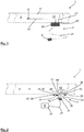
- the floor panel system 1' comprises a floor panel element 3', a temperature sensor device 5', and a connector device 7', and a control unit 9'.
- the floor panel element 3' comprises a panel structure 11' and a panel heater device 13'.
- the temperature sensor device 5' is provided inside the floor panel element 3' and connected to the connector device 7' by internal sensor wiring 15'.
- the panel heater device 13' is provided inside or in connection to the panel structure 11' and is connected to the connector device 7' by internal heater wiring 17'.
- the connector device 7' comprises a connector case 19' which is fixedly connected to the floor panel element 3' at its outside 20', and a power and data cable arrangement 21' connected to the connector case 19' at its one end and to the control unit 9' at its other end.
- FIG. 2 illustrates a heated floor panel system 1 for an aircraft according to the invention.
- the floor panel system 1 shown in Fig. 2 represents a more general embodiment that covers both alternative embodiments shown in Fig. 3 and Fig. 4 .
- the floor panel system 1 Similar to the prior art floor panel system 1' shown in Fig. 1 , the floor panel system 1 according to the invention and shown in Fig. 2 comprises a floor panel element 3, a temperature sensor device 5, a connector device 7, and a control unit 9.
- the floor panel element 3 includes a panel structure 11 for absorbing forces applied to the floor panel element 3, and a panel heater device 13 in the form of a heater layer included inside the panel structure 11.
- the temperature sensor device 5 is configured for detecting the temperature at a specific location of the floor panel element 3.
- the connector device 7 comprises a connector case 19 that is connected to the floor panel element 3 at its outside 20, and a power and data cable arrangement 21 connecting the connector case 19 to the control unit 9.
- the connector device 7 further comprises a power link 23 and a data link 25 both included in the connector case 19.
- the power link 23 provides an electric power connection from the panel heater device 13 to the power and data cable arrangement 21 and via the power and data cable arrangement 21 to an electric power supply 27 at the control unit 9.
- the data link 25 provides a data connection from the temperature sensor device 5 to the power and data cable arrangement 21 and via the power and data cable arrangement 21 to the control unit 9.
- the floor panel system 1 has the temperature sensor device 5 located in the connector device 7, in particular in the connector case 19, instead of in the floor panel element 3.
- the temperature sensor device 5 is connected to the floor panel element 3 via a thermal conductor element 29.
- the thermal conductor element 29 is formed as a metallic pin that conducts the heat from inside the floor panel element 3 to the temperature sensor device 5 in the connector case 19.
- the power and data cable arrangement 21 is removably connected to the connector case 19 via a cable connector 31 provided at the connector case 19.
- the connector case 19 is removably connected to the floor panel element 3 via a plug and socket connection 33.
- the connector case 19 comprises a flange portion 35 including a screw connection 37 for securing the connector case 19 to the floor panel element 3.
- the thermal conductor element 29 is fixedly connected to the floor panel element 3 and removably connected to the connector case 19.
- the floor panel element 3 comprises at its outside 20 a connector surface 39 providing an interface to the connector case 19.
- the thermal conductor element 29 comprises a panel portion 41 extending from the connector surface 39 to the inside 43 of the floor panel element 3, where it is fixed.
- the thermal conductor element 29 comprises a connector portion 45 projecting from the connector surface 39 away from the floor panel element 3.
- the connector case 19 comprises a thermal conductor recess 47 connected to the temperature sensor device 5 and removably receiving the connector portion 45 such that the connector portion 45 contacts the temperature sensor device 5. In such a way, the connector portion 45 functions as a plug and the thermal conductor recess 47 functions as a related socket.
- the floor panel element 3 comprises an electric conductor element 49 having an internal portion 51 extending from the connector surface 39 to the panel heater device 13 inside the floor panel element 3, where it is fixed.
- the electric conductor element 49 further has an external portion 53 projecting from the connector surface 39 away from the floor panel element 3.
- the connector case 19 comprises an electric conductor recess 55 connected to the power link 23 and removably receiving the external portion 53 such that the external portion 53 contacts the power link 23. In such a way, the external portion 53 functions as a plug and the electric conductor recess 55 functions as a related socket.
- the control unit 9 comprises the electric power supply 27 and is configured to control the electric power supplied by the electric power supply 27 via the power and data cable arrangement 21 and the power link 23 to the panel heater device 13, in dependence of temperature data received from the temperature sensor device 5 via the data link 25 and the power and data cable arrangement 21.
- the power and data cable arrangement 21 comprises a data cable 57 and a power cable 59, wherein via the cable connector 31 the data link 25 is connected to the data cable 57 and the power link 23 is connected to the power cable 59.
- the connector device 7 comprises a power line communication adapter unit 61 which connects the data link 25 to the power link 23, so that data, in particular temperature data from the temperature sensor device 5 provided by the data link 25, can be transferred via the electric power transferred through the power link 23.
- the power and data cable arrangement 21 comprises only a power cable 59, wherein the power link 23 is connected to the power cable 59 via the cable connector 31, and wherein the control unit 9 is adapted to receive data via the power cable 59.
- the power link 23 is connected to a Ground Fault Indicator Unit 63 provided in the connector case 19.
- the Ground Fault Indicator Unit 63 is configured to detect a fault current by comparing electric current in the power link 23 streaming to and back from the panel heater device 13.
- the Ground Fault Indicator Unit 63 comprises an overcurrent generator 65 configured to generate an overcurrent in the power link 23 upon detection of a fault current.
- the control unit 9 is configured to switch off the electric power supply 27 upon detection of the overcurrent.
- the Ground Fault Indicator Unit 63 comprises a fault signal generator 67 configured to generate a fault signal upon detection of a fault current, and send it to the control unit 9 via the power link 23 and the power cable 59. Further, the control unit 9 is configured to switch off the electric power supply 27 upon receipt of the fault signal.
Landscapes
- Engineering & Computer Science (AREA)
- Mechanical Engineering (AREA)
- Aviation & Aerospace Engineering (AREA)
- Physics & Mathematics (AREA)
- Thermal Sciences (AREA)
- Chemical & Material Sciences (AREA)
- Combustion & Propulsion (AREA)
- General Engineering & Computer Science (AREA)
- Central Heating Systems (AREA)
Description
- The present invention relates to a heated floor panel system for an aircraft, in particular for the cabin floor in the door or galley areas of an aircraft. Also disclosed is an aircraft, comprising the floor panel system according to any of the described embodiments, wherein the floor panel system is installed preferably in a door area or in a galley area of the aircraft.
- The floor panel system comprises a floor panel element, a temperature sensor device, and a connector device. The floor panel element includes a panel structure for transmitting forces applied to the floor panel, e.g. by passengers, and a panel heater device for heating the floor panel element. The panel heater device may be formed, e.g., as a heater layer, and may preferably be integrated into the panel structure. The temperature sensor device is configured for detecting the temperature at the floor panel element, in particular at one or more specific locations of the panel heater device and/or of the panel structure. The connector device is connected to the floor panel element, preferably from the outset of the floor panel element. The connector device comprises a power link for providing or supporting an electric power connection between the panel heater device and an electric power supply. Further, the connector device comprises a data link for providing or supporting a data connection between the temperature sensor device and a control unit, wherein data may be transferred analog or digitally. Preferably, the control unit relates to the Ice Protection Control Unit (IPCU).
- Such floor panel systems are known in the art and commonly used in passenger aircrafts, see for example
EP2679486 . The known floor panel systems comprise a temperature sensor device which is located inside the floor panel element. The connector device comprises a connector case which is fixedly connected to the floor panel element, and which is connected to the temperature sensor device via internal sensor wiring as well as to the panel heater device via internal heater wiring. The connector device further comprises a power and data cable at its one end fixedly connected to the connector case and at its other end removably connected to the Ice Protection Control Unit. However, such floor panel systems have a rather complicated construction which does not allow that the floor panel element and the connector device can be separated from one another and used independently. When one of the floor panel element and the connector device has to be replaced, e.g. due to a defect or maintenance, the entire floor panel system has to be replaced. - Therefore, the object of the present invention is to provide a floor panel system including a floor panel element which has a possibly simple construction and which can be used independently from the connector device.
- This object is achieved by the temperature sensor device being located in the connector device and connected to the floor panel element via a thermal conductor element. In such a way, the temperature of the floor panel element can be detected without the temperature sensor device being located in the floor panel element, simply by the thermal conductor element conducting the heat of the floor panel element out to the temperature sensor device provided in the connector device. Not only the temperature sensor device but also the internal sensor wiring can be removed from the floor panel element that way. The floor panel element has a much simpler construction and can much easier be produced and used, independently from the connector device.
- According to a preferred embodiment, the connector device is removably connected to the floor panel element. In particular, it is preferred that the connector device is connected to the floor panel element via a plug and socket connection. Such plug and socket connection preferably includes a female part which is arranged on one of the connector device and the floor panel element, and a male part which is arranged on the other of the connector device and the floor panel element, wherein the female and male parts are removably engaging one another. In such a way, the floor panel element and the connector device can easily be removed from one another, so that one of both can be exchanged without influencing the other. For example, when the connector device has a defect, it can simply be plugged out of the floor panel element and be removed or replaced without the floor panel element needing to be replaced, which can save a lot of work during maintenance of the aircraft. Also preferably, the connector device comprises a flange and a screw connection for securing the connector device to the floor panel element.
- According to another preferred embodiment the thermal conductor element is formed as a pin made of a thermally conductive material, preferably a metal, such as copper. Such a thermally conductive pin may reliably conduct the heat from the floor panel element to the temperature sensor device in the connector device, in order to sufficiently precise detect the temperature at the floor panel element. Further, such a pin-shaped thermal conductor element can simply be plugged in the connector device or in the floor panel element when a removable connection between the floor panel element and the connector device is intended.
- According to yet another preferred embodiment the thermal conductor element is fixedly connected to the floor panel element and removably connected to the connector device. In particular, the thermal conductor element at its one end extends inside the floor panel element in connection to the panel structure and/or the panel heater device, where it is fixedly connected, and at its other end extends inside the connector device in contact to the temperature sensor device, where it is removably connected. In such a way, the connector device does not comprise any projecting parts when it is removed from the floor panel element. However, the fixed and removable connection may also be reversed, so that the thermal conductor element is fixedly connected to the connector device and removably connected to the floor panel element.
- In particular, it is preferred that the floor panel element comprises at its outside a connector surface for providing an interface to the connector device. The thermal conductor element comprises a panel portion extending from the connector surface to the inside of the floor panel element, where it is preferably fixed, and a connector portion projecting from the connector surface away from the floor panel element. The connector device comprises a thermal conductor recess connected to the temperature sensor device and removably receiving the connector portion, such that the connector portion contacts the sensor device. In such a way, the connector portion is formed as a plug and the thermal conductor recess is formed as a socket, which together form a plug-and-socket connection. However, the connector portion and the thermal conductor recess might also be arranged reversely, so that the connector portion projects from the surface of the connector device into the thermal conductor recess provided in the connector surface of the floor panel element.
- Further particular, it is preferred that the floor panel element comprises an electric conductor element having an internal portion extending from the connector surface to the panel heater device, preferably inside the floor panel element, and an external portion projecting from the connector surface away from the floor panel element. Further, the connector device comprises an electric conductor recess connected to the power link and removably receiving the external portion, such that the external portion contacts the power link. In such a way, the external portion is formed as a plug and the electric conductor recess is formed as a socket, so that they together form a plug-and-socket connection. However, the external portion and the electric conductor recess might also be arranged reversely, so that the external portion projects away from the connector device and into the electric conductor recess provided in the connector surface of the floor panel element.
- According to a further preferred embodiment, the connector device comprises a connector case, wherein the temperature sensor device, the data link and the power link are arranged at least partially inside the connector case, and wherein the data link is connected to the temperature sensor device, preferably in the connector case. In such a manner, the connector case can be safely touched by a technician and easily be removed from the floor panel element or connected to the floor panel element. Also, the connector case can easily be replaced as such. Preferably, the connector case is removably connected to the floor panel element via a plug and socket connection.
- In particular, it is preferred that the connector device comprises a power and data cable arrangement for providing a data connection between the connector case and a control unit, and a power connection between the connector case and an electric power supply. The connector case comprises a cable connector connected to the power and data cable arrangement. Preferably, the power and data cable arrangement is removably connected to the cable connector, so that the connector case and the power and data cable arrangement can be treated as separate units and be replaced separately from one another.
- Further, it is preferred that the floor panel system comprises a control unit connected to the power and data cable arrangement and connected to the connector case via the power and data cable arrangement. The control unit comprises an electric power supply and is configured to control the electric power supplied by the electric power supply via the power and data cable arrangement and the power link to the panel heater device, in dependence of temperature data received from the temperature sensor device via the data link and the power and data cable arrangement. The control unit is preferably formed as the Ice Protection Control Unit (IPCU). By the control unit the electric power supplied to the panel heater device and thus the heat generated by the panel heater device can be controlled in dependence of the temperature in the floor panel element as detected by the temperature sensor device.
- It is also particularly preferred that the power and data cable arrangement comprises a data cable for transferring data, in particular temperature data, and a power cable for transferring electric power. Via the cable connector the data link is connected to the data cable and the power link is connected to the power cable. In such a way, the power and data cable arrangement provides two separate cables for the transfer of power and data between the control unit and the connector case.
- Alternatively, it is preferred that the connector device comprises a power line communication (PLC) adapter unit which connects the data link to the power link so that the data from the temperature sensor device provided by the data link can be transferred via the electric power transferred through the power link. The power line communication adapter unit is preferably arranged in the connector case and can be formed e.g. as a DLAN adapter. The power and data cable arrangement comprises a power cable for transferring electric power, and preferably does not comprise a separate data cable besides the power cable. The power link is connected to the power cable via the cable connector. In this embodiment, the control unit is preferably adapted to receive data via the power cable, e.g. by a related adapter configured to read the transferred data, in particular temperature data, out of the electric power transferred through the power cable. In such a way, no specific data cable is required and the power and data cable arrangement may comprise only one power cable transferring both power and data.
- According to a preferred embodiment the power link is connected to a Ground Fault Indicator (GFI) unit configured to detect a fault current in the power link by comparing electric current streaming to and back from the panel heater device. The Ground Fault Indicator Unit is preferably arranged in the connector case. By the Ground Fault Indicator Unit a fault current due to, e.g., a short circuit can be detected and indicated so that the electric power supply can be switched off.
- In the case that no power line communication adapter unit is provided, it is particularly preferred that the Ground Fault Indicator Unit comprises an overcurrent generator configured to generate an overcurrent in the power link, which is transferred to the control unit by the power cable, upon detection of a fault current. The control unit is configured to detect the overcurrent and switch off the electric power supply upon detection of the overcurrent. In such a way, the electric power supply can be switched off upon detection of a fault current in order to protect the floor panel system for the embodiment with no PLC adapter unit.
- Alternatively, when a power line communication adapter unit is provided, the Ground Fault Indicator Unit preferably comprises a fault signal generator configured to generate a fault signal upon detection of a fault current, and send the fault signal to the control unit via the power link and the power cable. The fault signal generator may thus preferably include a power line communication adapter for adapting the fault signal in order to be transferred via the electric current in the power cable. The control unit is configured to receive the fault signal and switch off the electric power supply upon receipt of the fault signal. In such a way, the electric power supply can be switched off upon detection of a fault current in order to protect the floor panel system, for the embodiment where a PLC adapter unit is provided.
- In the following, preferred embodiments of the invention are explained in further detail by means of a drawing. The drawing shows in
- Fig. 1
- a floor panel system as known in the art,
- Fig. 2
- a schematic diagram of a more general embodiment of the floor panel system according to the present invention,
- Fig. 3
- a detailed schematic diagram of a first alternative embodiment of the floor panel system as shown in
Fig. 2 , and - Fig. 4
- a detailed schematic diagram of a second alternative embodiment of the floor panel system as shown in
Fig. 2 . - In
Fig. 1 a prior art heated floor panel system 1' for an aircraft is illustrated. The floor panel system 1' comprises a floor panel element 3', a temperature sensor device 5', and a connector device 7', and a control unit 9'. The floor panel element 3' comprises a panel structure 11' and a panel heater device 13'. The temperature sensor device 5' is provided inside the floor panel element 3' and connected to the connector device 7' by internal sensor wiring 15'. The panel heater device 13' is provided inside or in connection to the panel structure 11' and is connected to the connector device 7' by internal heater wiring 17'. The connector device 7' comprises a connector case 19' which is fixedly connected to the floor panel element 3' at its outside 20', and a power and data cable arrangement 21' connected to the connector case 19' at its one end and to the control unit 9' at its other end. - In contrast,
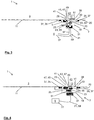
Fig. 2 illustrates a heatedfloor panel system 1 for an aircraft according to the invention. Thefloor panel system 1 shown inFig. 2 represents a more general embodiment that covers both alternative embodiments shown inFig. 3 and Fig. 4 . - Similar to the prior art floor panel system 1' shown in
Fig. 1 , thefloor panel system 1 according to the invention and shown inFig. 2 comprises afloor panel element 3, atemperature sensor device 5, aconnector device 7, and acontrol unit 9. Thefloor panel element 3 includes apanel structure 11 for absorbing forces applied to thefloor panel element 3, and apanel heater device 13 in the form of a heater layer included inside thepanel structure 11. Thetemperature sensor device 5 is configured for detecting the temperature at a specific location of thefloor panel element 3. Theconnector device 7 comprises aconnector case 19 that is connected to thefloor panel element 3 at its outside 20, and a power anddata cable arrangement 21 connecting theconnector case 19 to thecontrol unit 9. Theconnector device 7 further comprises apower link 23 and adata link 25 both included in theconnector case 19. Thepower link 23 provides an electric power connection from thepanel heater device 13 to the power anddata cable arrangement 21 and via the power anddata cable arrangement 21 to anelectric power supply 27 at thecontrol unit 9. The data link 25 provides a data connection from thetemperature sensor device 5 to the power anddata cable arrangement 21 and via the power anddata cable arrangement 21 to thecontrol unit 9. - In contrast to the prior art floor panel system 1', the
floor panel system 1 according to the invention has thetemperature sensor device 5 located in theconnector device 7, in particular in theconnector case 19, instead of in thefloor panel element 3. Thetemperature sensor device 5 is connected to thefloor panel element 3 via athermal conductor element 29. Thethermal conductor element 29 is formed as a metallic pin that conducts the heat from inside thefloor panel element 3 to thetemperature sensor device 5 in theconnector case 19. The power anddata cable arrangement 21 is removably connected to theconnector case 19 via acable connector 31 provided at theconnector case 19. Theconnector case 19 is removably connected to thefloor panel element 3 via a plug andsocket connection 33. Theconnector case 19 comprises a flange portion 35 including a screw connection 37 for securing theconnector case 19 to thefloor panel element 3. - The
thermal conductor element 29 is fixedly connected to thefloor panel element 3 and removably connected to theconnector case 19. Thefloor panel element 3 comprises at its outside 20 aconnector surface 39 providing an interface to theconnector case 19. Thethermal conductor element 29 comprises apanel portion 41 extending from theconnector surface 39 to the inside 43 of thefloor panel element 3, where it is fixed. Further, thethermal conductor element 29 comprises a connector portion 45 projecting from theconnector surface 39 away from thefloor panel element 3. Theconnector case 19 comprises a thermal conductor recess 47 connected to thetemperature sensor device 5 and removably receiving the connector portion 45 such that the connector portion 45 contacts thetemperature sensor device 5. In such a way, the connector portion 45 functions as a plug and the thermal conductor recess 47 functions as a related socket. - Further, the
floor panel element 3 comprises anelectric conductor element 49 having aninternal portion 51 extending from theconnector surface 39 to thepanel heater device 13 inside thefloor panel element 3, where it is fixed. Theelectric conductor element 49 further has an external portion 53 projecting from theconnector surface 39 away from thefloor panel element 3. Theconnector case 19 comprises an electric conductor recess 55 connected to thepower link 23 and removably receiving the external portion 53 such that the external portion 53 contacts thepower link 23. In such a way, the external portion 53 functions as a plug and the electric conductor recess 55 functions as a related socket. - The
control unit 9 comprises theelectric power supply 27 and is configured to control the electric power supplied by theelectric power supply 27 via the power anddata cable arrangement 21 and thepower link 23 to thepanel heater device 13, in dependence of temperature data received from thetemperature sensor device 5 via thedata link 25 and the power anddata cable arrangement 21. - In
Figs. 3 and 4 two alternative embodiments of thefloor panel system 1 ofFig. 2 are illustrated. In the embodiment shown inFig. 3 the power anddata cable arrangement 21 comprises adata cable 57 and apower cable 59, wherein via thecable connector 31 thedata link 25 is connected to thedata cable 57 and thepower link 23 is connected to thepower cable 59. Alternatively, in the embodiment shown inFig. 4 theconnector device 7 comprises a power linecommunication adapter unit 61 which connects thedata link 25 to thepower link 23, so that data, in particular temperature data from thetemperature sensor device 5 provided by thedata link 25, can be transferred via the electric power transferred through thepower link 23. The power anddata cable arrangement 21 comprises only apower cable 59, wherein thepower link 23 is connected to thepower cable 59 via thecable connector 31, and wherein thecontrol unit 9 is adapted to receive data via thepower cable 59. - In both the embodiment shown in
Fig. 3 and the embodiment shown inFig. 4 , thepower link 23 is connected to a Ground Fault Indicator Unit 63 provided in theconnector case 19. The Ground Fault Indicator Unit 63 is configured to detect a fault current by comparing electric current in thepower link 23 streaming to and back from thepanel heater device 13. In the embodiment shown inFig. 3 the Ground Fault Indicator Unit 63 comprises an overcurrent generator 65 configured to generate an overcurrent in thepower link 23 upon detection of a fault current. Further, thecontrol unit 9 is configured to switch off theelectric power supply 27 upon detection of the overcurrent. Alternatively, in the embodiment shown inFig. 4 the Ground Fault Indicator Unit 63 comprises a fault signal generator 67 configured to generate a fault signal upon detection of a fault current, and send it to thecontrol unit 9 via thepower link 23 and thepower cable 59. Further, thecontrol unit 9 is configured to switch off theelectric power supply 27 upon receipt of the fault signal.
Claims (15)
- A heated floor panel system (1) for an aircraft, said floor panel system (1) comprising
a floor panel element (3) including a panel structure (11) for transmitting forces applied to the floor panel element (3), and a panel heater device (13) for heating the floor panel element (3),
a temperature sensor device (5) for detecting the temperature at the floor panel element (3), and
a connector device (7) connected to the floor panel element (3), wherein the connector device (7) comprises a power link (23) for providing an electric power connection between the panel heater device (13) and an electric power supply (27), and a data link (25) for providing a data connection between the temperature sensor device (5) and a control unit (9),
characterized in that
the temperature sensor device (5) is located in the connector device (7) and connected to the floor panel element (3) via a thermal conductor element (29). - The floor panel system according to claim 1, wherein the connector device (7) is removably connected to the floor panel element (3).
- The floor panel system according to claim 2, wherein the connector device (7) is connected to the floor panel element (3) via a plug and socket connection (33).
- The floor panel system according to any of claims 1 to 3, wherein the thermal conductor element (29) is formed as a pin made of thermally conductive material.
- The floor panel system according to any of claims 1 to 4, wherein the thermal conductor element (29) is fixedly connected to the floor panel element (3) and removably connected to the connector device (7).
- The floor panel system according to claim 5, wherein the floor panel element (3) comprises at its outside (20) a connector surface (39),
wherein the thermal conductor element (29) comprises a panel portion (41) extending from the connector surface (39) to the inside (43) of the floor panel element (3), and a connector portion (45) projecting from the connector surface (39) away from the floor panel element (3), and
wherein the connector device (7) comprises a thermal conductor recess (47) connected to the temperature sensor device (5) and removably receiving the connector portion (45). - The floor panel system according to claim 6, wherein the floor panel element (3) comprises an electric conductor element (49) having an internal portion (51) extending from the connector surface (39) to the panel heater device (13), and an external portion (53) projecting from the connector surface (39) away from the floor panel element (3), and
wherein the connector device (7) comprises an electric conductor recess (55) connected to the power link (23) and removably receiving the external portion (53). - The floor panel system according to any of claims 1 to 7, wherein the connector device (7) comprises a connector case (19), and
wherein the data link (25) and the power link (23) are arranged inside the connector case (19). - The floor panel system according to claim 8, wherein the connector device (7) comprises a power and data cable arrangement (21), and
wherein the connector case (19) comprises a cable connector (31) connected to the power and data cable arrangement (21). - The floor panel system according to claim 9, further comprising a control unit (9) connected to the power and data cable arrangement (21),
wherein the control unit (9) comprises an electric power supply (27), and
wherein the control unit (9) is configured to control the electric power supplied by the electric power supply (27) via the power and data cable arrangement (21) and the power link (23) to the panel heater device (13), in dependence of temperature data received from the temperature sensor device (5) via the data link (25) and the power and data cable arrangement (21). - The floor panel system according to claim 9 or 10, wherein the power and data cable arrangement (21) comprises a data cable (57) and a power cable (59), and
wherein via the cable connector (31) the data link (25) is connected to the data cable (57) and the power link (23) is connected to the power cable (59). - The floor panel system according to claim 9 or 10, wherein the connector device (7) comprises a power line communication adapter (61) unit which connects the data link (25) to the power link (23),
wherein the power and data cable arrangement (21) comprises a power cable (59), and
wherein the power link (23) is connected to the power cable (59) via the cable connector (31). - The floor panel system according to any of claims 1 to 12, wherein the power link (23) is connected to a Ground Fault Indicator unit (63) configured to detect a fault current by comparing electric current streaming to and back from the panel heater device (13).
- The floor panel system according to claim 13 when depending from claims 10 and 11, wherein the Ground Fault Indicator unit (63) comprises an overcurrent generator (65) configured to generate an overcurrent in the power link (23) upon detection of a fault current, and
wherein the control unit (9) is configured to detect the overcurrent and switch off the electric power supply (27) upon detection of the overcurrent. - The floor panel system according to claim 13 when depending from claims 10 and 12, wherein the Ground Fault Indicator unit (63) comprises a fault signal generator (67) configured to generate a fault signal upon detection of a fault current, and send it to the control unit (9) via the power link (23) and the power cable (59), and
wherein the control unit (9) is configured to receive the fault signal and switch off the electric power supply (27) upon receipt of the fault signal.
Priority Applications (2)
| Application Number | Priority Date | Filing Date | Title |
|---|---|---|---|
| EP15189160.3A EP3153402B1 (en) | 2015-10-09 | 2015-10-09 | A heated floor panel system for an aircraft |
| US15/288,347 US10750575B2 (en) | 2015-10-09 | 2016-10-07 | Heated floor panel system for an aircraft |
Applications Claiming Priority (1)
| Application Number | Priority Date | Filing Date | Title |
|---|---|---|---|
| EP15189160.3A EP3153402B1 (en) | 2015-10-09 | 2015-10-09 | A heated floor panel system for an aircraft |
Publications (2)
| Publication Number | Publication Date |
|---|---|
| EP3153402A1 EP3153402A1 (en) | 2017-04-12 |
| EP3153402B1 true EP3153402B1 (en) | 2018-04-25 |
Family
ID=54292690
Family Applications (1)
| Application Number | Title | Priority Date | Filing Date |
|---|---|---|---|
| EP15189160.3A Active EP3153402B1 (en) | 2015-10-09 | 2015-10-09 | A heated floor panel system for an aircraft |
Country Status (2)
| Country | Link |
|---|---|
| US (1) | US10750575B2 (en) |
| EP (1) | EP3153402B1 (en) |
Families Citing this family (5)
| Publication number | Priority date | Publication date | Assignee | Title |
|---|---|---|---|---|
| US20180298611A1 (en) * | 2017-04-17 | 2018-10-18 | David R. Hall | Configurable Hydronic Structural Panel |
| DE102019133312A1 (en) * | 2019-12-06 | 2021-06-10 | Airbus Operations Gmbh | Heatable floor panel system for an aircraft, method for producing a heated floor panel, and aircraft |
| EP4305653A1 (en) | 2021-03-12 | 2024-01-17 | Essex Industries, Inc. | Rocker switch |
| WO2022197730A1 (en) | 2021-03-15 | 2022-09-22 | Essex Industries, Inc. | Five-position switch |
| DE102021112827A1 (en) * | 2021-05-18 | 2022-11-24 | Ke Kelit Kunststoffwerk Gmbh | Electric surface heating with an additional function not related to heating, and method of operation |
Family Cites Families (21)
| Publication number | Priority date | Publication date | Assignee | Title |
|---|---|---|---|---|
| US4055777A (en) * | 1976-11-02 | 1977-10-25 | The United States Of America As Represented By The Administrator Of The National Aeronautics And Space Administration | Window comparator |
| US4581522A (en) * | 1981-10-07 | 1986-04-08 | Intermountain Thermafloor, Inc. | Electrical heating system including a mesh heating element |
| US4633061A (en) * | 1982-11-18 | 1986-12-30 | Matsushita Electric Industrial Co., Ltd. | Thermostatically controlled electric seat heaters for vehicles |
| JPS6033783U (en) * | 1983-08-12 | 1985-03-07 | 松下電器産業株式会社 | electric floor heating equipment |
| US6072152A (en) * | 1994-11-16 | 2000-06-06 | Fleetheet Llc | Heater control device |
| US5835322A (en) * | 1997-07-07 | 1998-11-10 | Donald E. Smith | Ground fault interrupt circuit apparatus for 400-Hz aircraft electrical systems |
| US6403935B2 (en) * | 1999-05-11 | 2002-06-11 | Thermosoft International Corporation | Soft heating element and method of its electrical termination |
| US6834159B1 (en) * | 1999-09-10 | 2004-12-21 | Goodrich Corporation | Aircraft heated floor panel |
| US6691923B2 (en) * | 2001-05-31 | 2004-02-17 | Goodrich Corporation | Low noise solid-state thermostat |
| US6697757B2 (en) * | 2001-09-19 | 2004-02-24 | Leviton Manufacturing Co., Ltd. | Local network based multiple sensor device with electrical load control means and with temperature sensor and heat detector that is exposed to ambient air by diffusion |
| US6737610B1 (en) * | 2003-01-08 | 2004-05-18 | Dekko Technologies, Inc. | Stranded heater wire with sensor |
| US20070053188A1 (en) * | 2005-09-06 | 2007-03-08 | Luminator Holding, L.P. | LED ultraviolet air sanitizer light fixture |
| US8371526B2 (en) * | 2006-01-12 | 2013-02-12 | Goodrich Corporation | Aircraft heater floor panel |
| US7557330B2 (en) * | 2006-05-12 | 2009-07-07 | Goodrich Corporation | Heated floor panel with integrated controller having ground fault interrupt circuit |
| US20080083720A1 (en) * | 2006-10-04 | 2008-04-10 | T-Ink, Inc. | Method of heating an article |
| US8285127B2 (en) * | 2007-09-05 | 2012-10-09 | Tpi Corporation | In-line duct supplemental heating and cooling device and method |
| US8749928B2 (en) * | 2009-12-23 | 2014-06-10 | Goodrich Corporation | Aircraft electrical appliance |
| US9046899B2 (en) * | 2011-11-01 | 2015-06-02 | Goodrich Corporation | Aircraft heating system |
| EP2679486A1 (en) * | 2012-06-29 | 2014-01-01 | Airbus Operations GmbH | Heated floor panel for an aircraft and aircraft having a heated floor panel |
| EP2719623B1 (en) * | 2012-10-10 | 2019-06-26 | Airbus Operations GmbH | Heating control unit comprising a sensor, ice protection system and method for controlling a heater |
| US10356847B2 (en) * | 2015-03-12 | 2019-07-16 | The Boeing Company | Composite panel with integrated heater system and associated methods for manufacturing |
-
2015
- 2015-10-09 EP EP15189160.3A patent/EP3153402B1/en active Active
-
2016
- 2016-10-07 US US15/288,347 patent/US10750575B2/en active Active
Non-Patent Citations (1)
| Title |
|---|
| None * |
Also Published As
| Publication number | Publication date |
|---|---|
| US20170105245A1 (en) | 2017-04-13 |
| US10750575B2 (en) | 2020-08-18 |
| EP3153402A1 (en) | 2017-04-12 |
Similar Documents
| Publication | Publication Date | Title |
|---|---|---|
| EP3153402B1 (en) | A heated floor panel system for an aircraft | |
| US10439336B2 (en) | Plug connector part having a temperature sensor device | |
| US20160039297A1 (en) | Charging plug, charging cable and charging method for an electric vehicle | |
| CN106575842B (en) | Plug-in connector with temperature sensor | |
| US11203264B2 (en) | Charging socket for an electrically driven vehicle | |
| CN107534255B (en) | Connector component with temperature monitoring device | |
| US11117479B2 (en) | Temperature-monitored charging system for transmitting electric charge currents | |
| US11845348B2 (en) | Charging plug for a motor vehicle, and load contact module for a charging plug | |
| US11529881B2 (en) | Temperature-monitored load contact module and cooled charging plug | |
| US10682916B2 (en) | Thermal management of electric vehicle coupler contacts | |
| EP2719623B1 (en) | Heating control unit comprising a sensor, ice protection system and method for controlling a heater | |
| CN107454877B (en) | Thermally monitored charging device | |
| US10985549B2 (en) | Fault current protection device for monitoring an electric load for a vehicle, and method for carrying out a self-test of a fault current sensor | |
| US20170334300A1 (en) | Charging System with Temperature Sensor | |
| CN102638025A (en) | Thermal protection system for electrical device | |
| US11465525B2 (en) | Measuring apparatus and method for capturing electrical energy transferred from a charging station | |
| AU2020247076B2 (en) | Circuit board for an electric vehicle charging station | |
| EP2752951B1 (en) | Device and Method for Preventing Arc Flashes | |
| CN104520129B (en) | For forbidding and allow the method and system of electric motor vehicle control module | |
| WO2014001304A1 (en) | Heated floor panel for an aircraft and aircraft having a heated floor panel | |
| US20220376525A1 (en) | Temperature monitored charging connector part | |
| CN111108653A (en) | High-voltage plug connection for a high-voltage plug connector of a motor vehicle, high-voltage on-board electrical system and motor vehicle | |
| EP3396863B1 (en) | Secured power and data communications for aircraft coupled to ground systems | |
| JP5949394B2 (en) | Local cleaning equipment | |
| ZA200904201B (en) | Railway jumper cable connector system |
Legal Events
| Date | Code | Title | Description |
|---|---|---|---|
| PUAI | Public reference made under article 153(3) epc to a published international application that has entered the european phase |
Free format text: ORIGINAL CODE: 0009012 |
|
| AK | Designated contracting states |
Kind code of ref document: A1 Designated state(s): AL AT BE BG CH CY CZ DE DK EE ES FI FR GB GR HR HU IE IS IT LI LT LU LV MC MK MT NL NO PL PT RO RS SE SI SK SM TR |
|
| AX | Request for extension of the european patent |
Extension state: BA ME |
|
| 17P | Request for examination filed |
Effective date: 20170926 |
|
| RBV | Designated contracting states (corrected) |
Designated state(s): AL AT BE BG CH CY CZ DE DK EE ES FI FR GB GR HR HU IE IS IT LI LT LU LV MC MK MT NL NO PL PT RO RS SE SI SK SM TR |
|
| GRAP | Despatch of communication of intention to grant a patent |
Free format text: ORIGINAL CODE: EPIDOSNIGR1 |
|
| INTG | Intention to grant announced |
Effective date: 20171108 |
|
| GRAA | (expected) grant |
Free format text: ORIGINAL CODE: 0009210 |
|
| GRAS | Grant fee paid |
Free format text: ORIGINAL CODE: EPIDOSNIGR3 |
|
| AK | Designated contracting states |
Kind code of ref document: B1 Designated state(s): AL AT BE BG CH CY CZ DE DK EE ES FI FR GB GR HR HU IE IS IT LI LT LU LV MC MK MT NL NO PL PT RO RS SE SI SK SM TR |
|
| REG | Reference to a national code |
Ref country code: GB Ref legal event code: FG4D |
|
| REG | Reference to a national code |
Ref country code: CH Ref legal event code: EP |
|
| REG | Reference to a national code |
Ref country code: AT Ref legal event code: REF Ref document number: 992584 Country of ref document: AT Kind code of ref document: T Effective date: 20180515 |
|
| REG | Reference to a national code |
Ref country code: IE Ref legal event code: FG4D |
|
| REG | Reference to a national code |
Ref country code: DE Ref legal event code: R096 Ref document number: 602015010347 Country of ref document: DE |
|
| REG | Reference to a national code |
Ref country code: NL Ref legal event code: MP Effective date: 20180425 |
|
| REG | Reference to a national code |
Ref country code: LT Ref legal event code: MG4D |
|
| PG25 | Lapsed in a contracting state [announced via postgrant information from national office to epo] |
Ref country code: NL Free format text: LAPSE BECAUSE OF FAILURE TO SUBMIT A TRANSLATION OF THE DESCRIPTION OR TO PAY THE FEE WITHIN THE PRESCRIBED TIME-LIMIT Effective date: 20180425 |
|
| REG | Reference to a national code |
Ref country code: FR Ref legal event code: PLFP Year of fee payment: 4 |
|
| PG25 | Lapsed in a contracting state [announced via postgrant information from national office to epo] |
Ref country code: ES Free format text: LAPSE BECAUSE OF FAILURE TO SUBMIT A TRANSLATION OF THE DESCRIPTION OR TO PAY THE FEE WITHIN THE PRESCRIBED TIME-LIMIT Effective date: 20180425 Ref country code: PL Free format text: LAPSE BECAUSE OF FAILURE TO SUBMIT A TRANSLATION OF THE DESCRIPTION OR TO PAY THE FEE WITHIN THE PRESCRIBED TIME-LIMIT Effective date: 20180425 Ref country code: LT Free format text: LAPSE BECAUSE OF FAILURE TO SUBMIT A TRANSLATION OF THE DESCRIPTION OR TO PAY THE FEE WITHIN THE PRESCRIBED TIME-LIMIT Effective date: 20180425 Ref country code: BG Free format text: LAPSE BECAUSE OF FAILURE TO SUBMIT A TRANSLATION OF THE DESCRIPTION OR TO PAY THE FEE WITHIN THE PRESCRIBED TIME-LIMIT Effective date: 20180725 Ref country code: FI Free format text: LAPSE BECAUSE OF FAILURE TO SUBMIT A TRANSLATION OF THE DESCRIPTION OR TO PAY THE FEE WITHIN THE PRESCRIBED TIME-LIMIT Effective date: 20180425 Ref country code: SE Free format text: LAPSE BECAUSE OF FAILURE TO SUBMIT A TRANSLATION OF THE DESCRIPTION OR TO PAY THE FEE WITHIN THE PRESCRIBED TIME-LIMIT Effective date: 20180425 Ref country code: NO Free format text: LAPSE BECAUSE OF FAILURE TO SUBMIT A TRANSLATION OF THE DESCRIPTION OR TO PAY THE FEE WITHIN THE PRESCRIBED TIME-LIMIT Effective date: 20180725 |
|
| PG25 | Lapsed in a contracting state [announced via postgrant information from national office to epo] |
Ref country code: GR Free format text: LAPSE BECAUSE OF FAILURE TO SUBMIT A TRANSLATION OF THE DESCRIPTION OR TO PAY THE FEE WITHIN THE PRESCRIBED TIME-LIMIT Effective date: 20180726 Ref country code: HR Free format text: LAPSE BECAUSE OF FAILURE TO SUBMIT A TRANSLATION OF THE DESCRIPTION OR TO PAY THE FEE WITHIN THE PRESCRIBED TIME-LIMIT Effective date: 20180425 Ref country code: RS Free format text: LAPSE BECAUSE OF FAILURE TO SUBMIT A TRANSLATION OF THE DESCRIPTION OR TO PAY THE FEE WITHIN THE PRESCRIBED TIME-LIMIT Effective date: 20180425 Ref country code: LV Free format text: LAPSE BECAUSE OF FAILURE TO SUBMIT A TRANSLATION OF THE DESCRIPTION OR TO PAY THE FEE WITHIN THE PRESCRIBED TIME-LIMIT Effective date: 20180425 |
|
| REG | Reference to a national code |
Ref country code: AT Ref legal event code: MK05 Ref document number: 992584 Country of ref document: AT Kind code of ref document: T Effective date: 20180425 |
|
| PG25 | Lapsed in a contracting state [announced via postgrant information from national office to epo] |
Ref country code: PT Free format text: LAPSE BECAUSE OF FAILURE TO SUBMIT A TRANSLATION OF THE DESCRIPTION OR TO PAY THE FEE WITHIN THE PRESCRIBED TIME-LIMIT Effective date: 20180827 |
|
| REG | Reference to a national code |
Ref country code: DE Ref legal event code: R097 Ref document number: 602015010347 Country of ref document: DE |
|
| PG25 | Lapsed in a contracting state [announced via postgrant information from national office to epo] |
Ref country code: SK Free format text: LAPSE BECAUSE OF FAILURE TO SUBMIT A TRANSLATION OF THE DESCRIPTION OR TO PAY THE FEE WITHIN THE PRESCRIBED TIME-LIMIT Effective date: 20180425 Ref country code: CZ Free format text: LAPSE BECAUSE OF FAILURE TO SUBMIT A TRANSLATION OF THE DESCRIPTION OR TO PAY THE FEE WITHIN THE PRESCRIBED TIME-LIMIT Effective date: 20180425 Ref country code: RO Free format text: LAPSE BECAUSE OF FAILURE TO SUBMIT A TRANSLATION OF THE DESCRIPTION OR TO PAY THE FEE WITHIN THE PRESCRIBED TIME-LIMIT Effective date: 20180425 Ref country code: EE Free format text: LAPSE BECAUSE OF FAILURE TO SUBMIT A TRANSLATION OF THE DESCRIPTION OR TO PAY THE FEE WITHIN THE PRESCRIBED TIME-LIMIT Effective date: 20180425 Ref country code: DK Free format text: LAPSE BECAUSE OF FAILURE TO SUBMIT A TRANSLATION OF THE DESCRIPTION OR TO PAY THE FEE WITHIN THE PRESCRIBED TIME-LIMIT Effective date: 20180425 Ref country code: AT Free format text: LAPSE BECAUSE OF FAILURE TO SUBMIT A TRANSLATION OF THE DESCRIPTION OR TO PAY THE FEE WITHIN THE PRESCRIBED TIME-LIMIT Effective date: 20180425 |
|
| PG25 | Lapsed in a contracting state [announced via postgrant information from national office to epo] |
Ref country code: IT Free format text: LAPSE BECAUSE OF FAILURE TO SUBMIT A TRANSLATION OF THE DESCRIPTION OR TO PAY THE FEE WITHIN THE PRESCRIBED TIME-LIMIT Effective date: 20180425 Ref country code: SM Free format text: LAPSE BECAUSE OF FAILURE TO SUBMIT A TRANSLATION OF THE DESCRIPTION OR TO PAY THE FEE WITHIN THE PRESCRIBED TIME-LIMIT Effective date: 20180425 |
|
| PLBE | No opposition filed within time limit |
Free format text: ORIGINAL CODE: 0009261 |
|
| STAA | Information on the status of an ep patent application or granted ep patent |
Free format text: STATUS: NO OPPOSITION FILED WITHIN TIME LIMIT |
|
| 26N | No opposition filed |
Effective date: 20190128 |
|
| PG25 | Lapsed in a contracting state [announced via postgrant information from national office to epo] |
Ref country code: SI Free format text: LAPSE BECAUSE OF FAILURE TO SUBMIT A TRANSLATION OF THE DESCRIPTION OR TO PAY THE FEE WITHIN THE PRESCRIBED TIME-LIMIT Effective date: 20180425 |
|
| REG | Reference to a national code |
Ref country code: CH Ref legal event code: PL |
|
| REG | Reference to a national code |
Ref country code: BE Ref legal event code: MM Effective date: 20181031 |
|
| PG25 | Lapsed in a contracting state [announced via postgrant information from national office to epo] |
Ref country code: LU Free format text: LAPSE BECAUSE OF NON-PAYMENT OF DUE FEES Effective date: 20181009 Ref country code: MC Free format text: LAPSE BECAUSE OF FAILURE TO SUBMIT A TRANSLATION OF THE DESCRIPTION OR TO PAY THE FEE WITHIN THE PRESCRIBED TIME-LIMIT Effective date: 20180425 |
|
| REG | Reference to a national code |
Ref country code: IE Ref legal event code: MM4A |
|
| PG25 | Lapsed in a contracting state [announced via postgrant information from national office to epo] |
Ref country code: LI Free format text: LAPSE BECAUSE OF NON-PAYMENT OF DUE FEES Effective date: 20181031 Ref country code: CH Free format text: LAPSE BECAUSE OF NON-PAYMENT OF DUE FEES Effective date: 20181031 Ref country code: BE Free format text: LAPSE BECAUSE OF NON-PAYMENT OF DUE FEES Effective date: 20181031 |
|
| PG25 | Lapsed in a contracting state [announced via postgrant information from national office to epo] |
Ref country code: IE Free format text: LAPSE BECAUSE OF NON-PAYMENT OF DUE FEES Effective date: 20181009 |
|
| PG25 | Lapsed in a contracting state [announced via postgrant information from national office to epo] |
Ref country code: AL Free format text: LAPSE BECAUSE OF FAILURE TO SUBMIT A TRANSLATION OF THE DESCRIPTION OR TO PAY THE FEE WITHIN THE PRESCRIBED TIME-LIMIT Effective date: 20180425 |
|
| PG25 | Lapsed in a contracting state [announced via postgrant information from national office to epo] |
Ref country code: MT Free format text: LAPSE BECAUSE OF NON-PAYMENT OF DUE FEES Effective date: 20181009 |
|
| PG25 | Lapsed in a contracting state [announced via postgrant information from national office to epo] |
Ref country code: TR Free format text: LAPSE BECAUSE OF FAILURE TO SUBMIT A TRANSLATION OF THE DESCRIPTION OR TO PAY THE FEE WITHIN THE PRESCRIBED TIME-LIMIT Effective date: 20180425 |
|
| PG25 | Lapsed in a contracting state [announced via postgrant information from national office to epo] |
Ref country code: HU Free format text: LAPSE BECAUSE OF FAILURE TO SUBMIT A TRANSLATION OF THE DESCRIPTION OR TO PAY THE FEE WITHIN THE PRESCRIBED TIME-LIMIT; INVALID AB INITIO Effective date: 20151009 Ref country code: MK Free format text: LAPSE BECAUSE OF NON-PAYMENT OF DUE FEES Effective date: 20180425 Ref country code: CY Free format text: LAPSE BECAUSE OF FAILURE TO SUBMIT A TRANSLATION OF THE DESCRIPTION OR TO PAY THE FEE WITHIN THE PRESCRIBED TIME-LIMIT Effective date: 20180425 |
|
| PG25 | Lapsed in a contracting state [announced via postgrant information from national office to epo] |
Ref country code: IS Free format text: LAPSE BECAUSE OF FAILURE TO SUBMIT A TRANSLATION OF THE DESCRIPTION OR TO PAY THE FEE WITHIN THE PRESCRIBED TIME-LIMIT Effective date: 20180825 |
|
| PGFP | Annual fee paid to national office [announced via postgrant information from national office to epo] |
Ref country code: GB Payment date: 20231020 Year of fee payment: 9 |
|
| PGFP | Annual fee paid to national office [announced via postgrant information from national office to epo] |
Ref country code: FR Payment date: 20231026 Year of fee payment: 9 Ref country code: DE Payment date: 20231020 Year of fee payment: 9 |