EP3153397A1 - A hybrid wire winch - Google Patents
A hybrid wire winch Download PDFInfo
- Publication number
- EP3153397A1 EP3153397A1 EP16200012.9A EP16200012A EP3153397A1 EP 3153397 A1 EP3153397 A1 EP 3153397A1 EP 16200012 A EP16200012 A EP 16200012A EP 3153397 A1 EP3153397 A1 EP 3153397A1
- Authority
- EP
- European Patent Office
- Prior art keywords
- winch
- hybrid drive
- drive wire
- wire winch
- hydraulic
- Prior art date
- Legal status (The legal status is an assumption and is not a legal conclusion. Google has not performed a legal analysis and makes no representation as to the accuracy of the status listed.)
- Granted
Links
Images



Classifications
-
- B—PERFORMING OPERATIONS; TRANSPORTING
- B66—HOISTING; LIFTING; HAULING
- B66C—CRANES; LOAD-ENGAGING ELEMENTS OR DEVICES FOR CRANES, CAPSTANS, WINCHES, OR TACKLES
- B66C23/00—Cranes comprising essentially a beam, boom, or triangular structure acting as a cantilever and mounted for translatory of swinging movements in vertical or horizontal planes or a combination of such movements, e.g. jib-cranes, derricks, tower cranes
- B66C23/18—Cranes comprising essentially a beam, boom, or triangular structure acting as a cantilever and mounted for translatory of swinging movements in vertical or horizontal planes or a combination of such movements, e.g. jib-cranes, derricks, tower cranes specially adapted for use in particular purposes
- B66C23/36—Cranes comprising essentially a beam, boom, or triangular structure acting as a cantilever and mounted for translatory of swinging movements in vertical or horizontal planes or a combination of such movements, e.g. jib-cranes, derricks, tower cranes specially adapted for use in particular purposes mounted on road or rail vehicles; Manually-movable jib-cranes for use in workshops; Floating cranes
- B66C23/52—Floating cranes
-
- B—PERFORMING OPERATIONS; TRANSPORTING
- B63—SHIPS OR OTHER WATERBORNE VESSELS; RELATED EQUIPMENT
- B63B—SHIPS OR OTHER WATERBORNE VESSELS; EQUIPMENT FOR SHIPPING
- B63B27/00—Arrangement of ship-based loading or unloading equipment for cargo or passengers
- B63B27/10—Arrangement of ship-based loading or unloading equipment for cargo or passengers of cranes
-
- B—PERFORMING OPERATIONS; TRANSPORTING
- B63—SHIPS OR OTHER WATERBORNE VESSELS; RELATED EQUIPMENT
- B63B—SHIPS OR OTHER WATERBORNE VESSELS; EQUIPMENT FOR SHIPPING
- B63B27/00—Arrangement of ship-based loading or unloading equipment for cargo or passengers
- B63B27/30—Arrangement of ship-based loading or unloading equipment for transfer at sea between ships or between ships and off-shore structures
-
- B—PERFORMING OPERATIONS; TRANSPORTING
- B66—HOISTING; LIFTING; HAULING
- B66C—CRANES; LOAD-ENGAGING ELEMENTS OR DEVICES FOR CRANES, CAPSTANS, WINCHES, OR TACKLES
- B66C13/00—Other constructional features or details
- B66C13/52—Details of compartments for driving engines or motors or of operator's stands or cabins
- B66C13/54—Operator's stands or cabins
-
- B—PERFORMING OPERATIONS; TRANSPORTING
- B66—HOISTING; LIFTING; HAULING
- B66C—CRANES; LOAD-ENGAGING ELEMENTS OR DEVICES FOR CRANES, CAPSTANS, WINCHES, OR TACKLES
- B66C23/00—Cranes comprising essentially a beam, boom, or triangular structure acting as a cantilever and mounted for translatory of swinging movements in vertical or horizontal planes or a combination of such movements, e.g. jib-cranes, derricks, tower cranes
- B66C23/16—Cranes comprising essentially a beam, boom, or triangular structure acting as a cantilever and mounted for translatory of swinging movements in vertical or horizontal planes or a combination of such movements, e.g. jib-cranes, derricks, tower cranes with jibs supported by columns, e.g. towers having their lower end mounted for slewing movements
- B66C23/163—Cranes comprising essentially a beam, boom, or triangular structure acting as a cantilever and mounted for translatory of swinging movements in vertical or horizontal planes or a combination of such movements, e.g. jib-cranes, derricks, tower cranes with jibs supported by columns, e.g. towers having their lower end mounted for slewing movements where only part of the column rotates, i.e. at least the bottom part is fixed
-
- B—PERFORMING OPERATIONS; TRANSPORTING
- B66—HOISTING; LIFTING; HAULING
- B66C—CRANES; LOAD-ENGAGING ELEMENTS OR DEVICES FOR CRANES, CAPSTANS, WINCHES, OR TACKLES
- B66C23/00—Cranes comprising essentially a beam, boom, or triangular structure acting as a cantilever and mounted for translatory of swinging movements in vertical or horizontal planes or a combination of such movements, e.g. jib-cranes, derricks, tower cranes
- B66C23/18—Cranes comprising essentially a beam, boom, or triangular structure acting as a cantilever and mounted for translatory of swinging movements in vertical or horizontal planes or a combination of such movements, e.g. jib-cranes, derricks, tower cranes specially adapted for use in particular purposes
- B66C23/36—Cranes comprising essentially a beam, boom, or triangular structure acting as a cantilever and mounted for translatory of swinging movements in vertical or horizontal planes or a combination of such movements, e.g. jib-cranes, derricks, tower cranes specially adapted for use in particular purposes mounted on road or rail vehicles; Manually-movable jib-cranes for use in workshops; Floating cranes
- B66C23/52—Floating cranes
- B66C23/53—Floating cranes including counterweight or means to compensate for list, trim, or skew of the vessel or platform
-
- B—PERFORMING OPERATIONS; TRANSPORTING
- B66—HOISTING; LIFTING; HAULING
- B66C—CRANES; LOAD-ENGAGING ELEMENTS OR DEVICES FOR CRANES, CAPSTANS, WINCHES, OR TACKLES
- B66C23/00—Cranes comprising essentially a beam, boom, or triangular structure acting as a cantilever and mounted for translatory of swinging movements in vertical or horizontal planes or a combination of such movements, e.g. jib-cranes, derricks, tower cranes
- B66C23/54—Cranes comprising essentially a beam, boom, or triangular structure acting as a cantilever and mounted for translatory of swinging movements in vertical or horizontal planes or a combination of such movements, e.g. jib-cranes, derricks, tower cranes with pneumatic or hydraulic motors, e.g. for actuating jib-cranes on tractors
-
- B—PERFORMING OPERATIONS; TRANSPORTING
- B66—HOISTING; LIFTING; HAULING
- B66C—CRANES; LOAD-ENGAGING ELEMENTS OR DEVICES FOR CRANES, CAPSTANS, WINCHES, OR TACKLES
- B66C23/00—Cranes comprising essentially a beam, boom, or triangular structure acting as a cantilever and mounted for translatory of swinging movements in vertical or horizontal planes or a combination of such movements, e.g. jib-cranes, derricks, tower cranes
- B66C23/62—Constructional features or details
- B66C23/64—Jibs
- B66C23/68—Jibs foldable or otherwise adjustable in configuration
-
- B—PERFORMING OPERATIONS; TRANSPORTING
- B66—HOISTING; LIFTING; HAULING
- B66D—CAPSTANS; WINCHES; TACKLES, e.g. PULLEY BLOCKS; HOISTS
- B66D1/00—Rope, cable, or chain winding mechanisms; Capstans
- B66D1/02—Driving gear
- B66D1/08—Driving gear incorporating fluid motors
-
- B—PERFORMING OPERATIONS; TRANSPORTING
- B66—HOISTING; LIFTING; HAULING
- B66D—CAPSTANS; WINCHES; TACKLES, e.g. PULLEY BLOCKS; HOISTS
- B66D1/00—Rope, cable, or chain winding mechanisms; Capstans
- B66D1/02—Driving gear
- B66D1/12—Driving gear incorporating electric motors
-
- B—PERFORMING OPERATIONS; TRANSPORTING
- B66—HOISTING; LIFTING; HAULING
- B66D—CAPSTANS; WINCHES; TACKLES, e.g. PULLEY BLOCKS; HOISTS
- B66D1/00—Rope, cable, or chain winding mechanisms; Capstans
- B66D1/28—Other constructional details
- B66D1/40—Control devices
- B66D1/48—Control devices automatic
- B66D1/52—Control devices automatic for varying rope or cable tension, e.g. when recovering craft from water
- B66D1/525—Control devices automatic for varying rope or cable tension, e.g. when recovering craft from water electrical
Definitions
- This invention relates to cranes and particularly to cranes located on the deck of a vessel.
- the present invention relates to a hybrid drive wire winch adapted for operation with a knuckle boom crane.
- cranes for on-ship/deck operation such as rotary jib cranes with or without telescopic boom, rotary boom cranes and knuckle boom cranes.
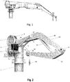
- knuckle boom cranes consist of a pedestal for interface with the deck, slewing bearings which provides rotation to a tower, the tower is engaged with a first main boom which is pivotally hinged to the tower, whilst the other end of the main boom is pivotally connected to the knuckle boom ( fig. 1 ).
- the knuckle boom is provided with one or more sheaves.
- Adjacent to the top of the tower and the pivot hinge of the main boom a winch Adjacent to the top of the tower and the pivot hinge of the main boom a winch is provided and optionally an operators cabin. Wire is fed from the winch via several sheaves to the sheave arranged at the extreme end of the knuckle boom and at its end the wire will typically be provided with a hook. Rotation of the winch will feed or hoist the hook at the end of the wire.
- the knuckle boom may be of a fixed type or a telescopic type.
- the knuckle boom design is well suited for use on ship as it provides good control of the payload as the main boom and the knuckle boom as well as the wire can be operated simultaneously. This means that the booms can be lowered so as to reduce the pendulum length of the hook and thereby reduce pendulum movements of the payload.
- Knuckle boom cranes suffers from some drawbacks the wire will have to travel over a numbers of sheaves which makes threading of the wire difficult, it means that there are several service points on the top of the booms which are not easily accessed as shown in a crane of the prior art in figure 1 .
- Knuckle boom cranes are usually hydraulic driven cranes, and the interface between the ship and the crane includes several hydraulic high pressure hoses in addition to this if the crane includes an operators cabin the interface will include electric power for feeding the control system in the operators' cabin.
- heave compensation is important for on-ship operation, and that knuckle boom cranes are particularly suited for heave compensation.
- the crane is of knuckle boom design which gives the operator the opportunity to place the load very precisely down in nearly any position within the area of the cranes working radius.
- the load can be transferred either by operating the winch or the booms or a combination of both.
- the crane structural system consists of pedestal, tower, machine house, operator's cabin and booms were the tower is the rotating part of the crane mounted on a slewing bearing on top of the pedestal.
- the main winch is equipped with active heave compensation and it has all required functionality for safe and efficient lifting operations.
- the crane has one hydraulic power unit supplying all the consumers with oil. Electric power is fed from the vessel.
- hybrid drive wire winch adapted for operation with a knuckle boom crane, where the hybrid drive wire winch at least comprises:
- the control system can be configured to provide automatic heave compensation signals to the frequency controller and the hydraulic power unit so as to provide for an active heave compensated winch.
- the hybrid drive wire winch further comprises a manual overload protection.
- the hybrid drive wire winch further comprises fail safe brakes.
- the fail safe brakes are spring applied and hydraulic released.
- the fail safe brakes are provided as two independent brakes, one on the hybrid drive wire winch drives and one directly on the drum.
- the hybrid drive wire winch further comprises a motion limiter.
- the motion limiter is provided as an encoder for calculation of an actual hook position.
- the frequency converter further is connected to the control system and to a second electric motor, where the second electric motor is in operational engagement with a variable hydraulic displacement pump, the hydraulic power unit includes the variable hydraulic displacement pump and the second motor.
- sheaves and pulleys operators house, operators cabin, crane cabin, crane house; boom cylinders and hydraulic cylinders
- a crane system basically consists of the following main components:
- Hydraulic power unit HPU
- the ship delivers electric power supply to the crane.
- the operation of the crane is electro hydraulic (hybrid system) and the hydraulic system is independent of any external to the crane hydraulic system i.e. being a self contained system. This provides for a neat and simple interface between the crane and the deck to which the crane is mounted.
- At least one electric pump builds up the pressure for the hydraulic system; the hydraulic system also includes a reservoir for the hydraulic fluid.
- electro hydraulic system The idea of an electro hydraulic system is that the "heavy work" is carried out by the hydraulics whilst acceleration and fine movements are controlled and carried out by electric motors/actuators. Further description of the electro hydraulic system, the hydraulic system, the electric system and control thereof is described below.
- a tower 2 is a tubular shaped member which is at its lower end arranged vertically on a pedestal. At its upper end an operator cabin 4 is fixed to the tower 2.
- a machine house 3 is arranged adjacent to the operator cabin 4.
- a winch 5 is rotatably arranged between two support plates +which extend out from an upper side of the tower 2 opposite of a main boom 14.
- the winch 5 is of an electro hydraulic type, thus heave compensation and movements with high acceleration are carried out by the electric motor internal of the winch whereas the movements with low acceleration are controlled by hydraulic motors.
- the winch is arranged external to the crane and a sheave is arranged where the winch 5 is arranged in the first embodiment of the invention described above.
- the crane control system is based on an Industrial Controller (IC), control cabinets and sensors.
- IC Industrial Controller
- the IC reads physical parameters such as boom angles, wire length on winch and crane load.
- the parameters are provided by sensors.
- Crane functions are controlled by joysticks, switches and an operator panel inside the cabin 4.
- the joysticks control the winch 5, slew and booms 12, 14.
- the response on joystick movement can be tuned.
- Interfaces between operator controls, sensors and actuators are based upon a distributed I/O system communicating via Bus.
- All sensor signals are routed to the industrial controller. Based on these signals the IC controls the crane, evaluates safety measures, activates alarms and presents necessary information on an operator display in the cabin 4.
- SWL safe working load
- the load measurement is performed by a load cell bolt, mounted in the wire sheave 10 at the second end of the knuckle boom.
- the load cell amplifier gives an analogue input signal to the IC.
- Encoders control the hook stop function of the winches 5.
- the encoder signals are input to the IC, which counts pulses from the sensors and also detect the direction of the motion. Via the operator display it is possible to reset the counting to zero and set span for the motion. The display will continuously show the actual wire paid out on the winch (from hook stop upper position).
- the Motion Reference Unit measures the vessels movements (roll, pitch, heave and heave acceleration). Based on the MRU signals and the crane position related to the vessel, the IC calculates the actual movement of the boom tip/second end of knuckle boom 12. During active heave compensation the MRU generates a reference/feedback signal to the control system in order to compensate for the boom tip movement.
- the operator can select the required system mode. Please note that the control system, under certain conditions, automatically will select one of the below modes.
- the main winch 5 can change between the modes shown in the figure 4 . Arrows indicate possible transitions.
- Table 1 Standby This is the default mode for the winch 5 when the control system is ON Normal In this mode the winch 5 is run from the joystick, the brakes are engaged during deck lift and disengaged during subsea lift.
- AHC This mode is used to compensate the ship movement caused by waves. AHC operation mode will keep the distance between the seabed and load constant.
- the AHC controller gets its set point from a MRU.
- the joystick may be used to both hoist and lower the payload while in AHC, but the sum of speed signals will never exceed the winch capacity.
- CT In this mode the unit gets its speed set point from a Constant Tension controller detecting rope tension variations, thereby keeping the rope tension near constant.
- the set point may be changed by the operator at any time. Detection of rope tension is carried out by a sensor. AOPS Automatic overload protection system (see safety functions for details) MOPS Manual overload protection system (see safety functions for details) Error Fault in the system, as example drive unit error, software communication failure or load drop.
- Table 2 Normal crane operation Functions Slewing (joysticks on operators chair) Main boom 14 Knuckle boom 12 Main winch 5 Armrest / operator panel Instrumentation / activators Emergency stop System on/off Joystick on/off MOPS main winch Emergency operation (emergency panel) Functions Slewing Main boom Knuckle boom Main winch
- the operational chair is according to one embodiment equipped with a joystick on each armrest, in addition there can be display with graphical user interface were system components can be selected. Each main component can be provided with its own page on the GUI were required information is available. Obviously other design with joysticks arranged on a pad with a gooseneck which facilitates movement of the pad is an alternative design.
- the GUI is microprocessor controlled hence the GUI scales well and it might be upgraded and reprogrammed.
- the armrest controls on the operators chair are:
- All joysticks may have two axes with spring return to zero.
- the operational speed is proportional to the handle movement but it is limited by the control system to give approximately constant power.
- the operator display provides interaction between the operator and the control system in order to assure safe operation of the crane in all modes. From the GUI, different systems components can be selected. These system components have a common GUI platform and the alternative window based screen images are of similar design.
- An operator panel can be located next to the operator's chair.
- the operator's panel contains buttons and switches for safety measures and operation of auxiliary equipment such as window wipers and washer, stereo and optionally for UHF/VHF.
- the emergency operation panel and its base unit are located in the operator cabin 4. There is one common panel for operation of all the crane functions.
- the emergency operation panel is portable and it is equipped with a cable for connection to the base unit. As there is no emergency stop button on the panel, it must be used within immediate reach of one. It is recommended that the emergency operation panel is used while seated in the operator chair.
- the handles on the emergency operation panel is “hold to run” type and their function is clearly marked.
- Table 3 Main winch MOPS, Manual overload protection
- the system can be activated at all time and at any configuration, including after emergency stop and power failure. When activated the system will maintain a retaining force of approx. 20% of maximum rated capacity. All other functions are overridden during activation.
- the valves to be activated are powered by UPS.
- Fail safe brake The Fail-Safe brakes are spring applied and hydraulic released, this means that it starts to brake when the oil pressure to the brake disappears. As this system is fitted with handling of personnel the winch has two independent brakes, one on the winch drives and one directly on the drum.
- AOPS Automatic overload protection The system continuously monitors the loads and load moment on the crane.
- Motion limiter An encoder is fitted to calculate the actual hook position. End stop is programmed in upper position and a bitter end is set (5 turns left with wire on the drum) Crane Main boom / knuckle boom Load holding valve and sensors for reduction of speed at end positions. Slewing Load holding valve and fail safe brake Hydraulic system Relief valves All hydraulic pressure lines are equipped with relief valves to prevent excessive pressure in the system. Electric system Overload protection The system is equipped with circuit breakers and the frequency drive has internal safety measures in case of over current, hot motor, communication error etc. Complete system Emergency stop When activated the unit will stop. (Hydraulic and electric energy will be cut off). Note: control system will still be operational.
- the crane can be designed as a self-contained unit without any hydraulic interface to the vessel.
- Hydraulic power unit drives and accumulator system which is dimensioned to allow operation at nominal speed and AHC capacities in accordance with industry standard regulations.
- the hydraulic system basically consist of the following components Hydraulic power unit (HPU)
- HPU Hydraulic power unit
- a combination of hydraulic and electrical motors is according to one embodiment provided for operation of the machinery.
- the winch 5 is a 150 Te winch for crane:
- At least one hydraulic motor such as Variable displacement hydraulic motor A6VM 1000 cm3.
- the number and combinations off drive units will vary depending on size and requirements for the equipment it is installed on.
- the hydraulic motors are mainly for load holding while the electric motors provide speed and acceleration.
- a manually operated emergency stop system leading to shut-down and stop of the crane movements is fitted. Simultaneously, the brakes are engaged in a progressive and safe manner. The emergency stop maintains its function regardless of any fault in the control system.
- the arrangement of the emergency stop system is designed so that no single failure will cause loss of duplicated essential or important equipment.
- the wire to be used is compact and rotation resistant. • The slewing speed is reduced at high loads.
Landscapes
- Engineering & Computer Science (AREA)
- Mechanical Engineering (AREA)
- Chemical & Material Sciences (AREA)
- Combustion & Propulsion (AREA)
- Ocean & Marine Engineering (AREA)
- Jib Cranes (AREA)
- Control And Safety Of Cranes (AREA)
Abstract
Description
- This invention relates to cranes and particularly to cranes located on the deck of a vessel. In particular the present invention relates to a hybrid drive wire winch adapted for operation with a knuckle boom crane.
- There are numerous types of cranes for on-ship/deck operation such as rotary jib cranes with or without telescopic boom, rotary boom cranes and knuckle boom cranes.
- Traditional knuckle boom cranes consist of a pedestal for interface with the deck, slewing bearings which provides rotation to a tower, the tower is engaged with a first main boom which is pivotally hinged to the tower, whilst the other end of the main boom is pivotally connected to the knuckle boom (
fig. 1 ). At its extreme other end the knuckle boom is provided with one or more sheaves. Adjacent to the top of the tower and the pivot hinge of the main boom a winch is provided and optionally an operators cabin. Wire is fed from the winch via several sheaves to the sheave arranged at the extreme end of the knuckle boom and at its end the wire will typically be provided with a hook. Rotation of the winch will feed or hoist the hook at the end of the wire. The knuckle boom may be of a fixed type or a telescopic type. - The knuckle boom design is well suited for use on ship as it provides good control of the payload as the main boom and the knuckle boom as well as the wire can be operated simultaneously. This means that the booms can be lowered so as to reduce the pendulum length of the hook and thereby reduce pendulum movements of the payload.
- Knuckle boom cranes suffers from some drawbacks the wire will have to travel over a numbers of sheaves which makes threading of the wire difficult, it means that there are several service points on the top of the booms which are not easily accessed as shown in a crane of the prior art in
figure 1 . - Knuckle boom cranes are usually hydraulic driven cranes, and the interface between the ship and the crane includes several hydraulic high pressure hoses in addition to this if the crane includes an operators cabin the interface will include electric power for feeding the control system in the operators' cabin.
- It shall also be mentioned that heave compensation is important for on-ship operation, and that knuckle boom cranes are particularly suited for heave compensation.
- It is an object according to the present invention to provide a wire winch adapted for operation with a knuckle boom crane that does not suffer from the disadvantages above.
- According to the present invention it is provided a wire winch adapted for operation with a knuckle boom crane that does not suffer from the drawbacks indicated above.
- Special attention has been given to ease access for service and maintenance. The crane is of knuckle boom design which gives the operator the opportunity to place the load very precisely down in nearly any position within the area of the cranes working radius. The load can be transferred either by operating the winch or the booms or a combination of both.
- The crane structural system consists of pedestal, tower, machine house, operator's cabin and booms were the tower is the rotating part of the crane mounted on a slewing bearing on top of the pedestal.
- The main winch is equipped with active heave compensation and it has all required functionality for safe and efficient lifting operations.
- Normal operation of the crane is performed from an operator chair located in the crane cabin. Emergency operation is performed through an emergency panel or by use of valve levers located in the crane. The crane has one hydraulic power unit supplying all the consumers with oil. Electric power is fed from the vessel.
- According to one embodiment it is provided:
- a) a winch with a wire positioned at an upper end of the tower so that the upper rim of the reel of the winch protrudes above the top of the tower; or a wire routing with a winch with a wire arranged external to the crane where the wire is fed to a first sheave arranged at an upper end of the tower so that the upper rim of the sheave protrudes above the top of the tower.
- A according to an aspect of the invention it is provided a hybrid drive wire winch adapted for operation with a knuckle boom crane, where the hybrid drive wire winch at least comprises:
- a) at least one electric motor and at least one hydraulic motor for operation of the winch;
- b) a control system;
- c) a frequency converter for speed and directional adjustment of the at least one electric motor and;
- d) a hydraulic power unit in operational engagement with a directional valve, where the directional valve controls the rotary direction of the winch.
- The control system can be configured to provide automatic heave compensation signals to the frequency controller and the hydraulic power unit so as to provide for an active heave compensated winch.
- In one aspect of the invention the hybrid drive wire winch further comprises a manual overload protection.
- In yet an aspect of the invention the hybrid drive wire winch further comprises fail safe brakes. In one aspect the fail safe brakes are spring applied and hydraulic released. In another aspect the fail safe brakes are provided as two independent brakes, one on the hybrid drive wire winch drives and one directly on the drum.
- In yet an aspect of the invention the hybrid drive wire winch further comprises a motion limiter. In one aspect of the invention the motion limiter is provided as an encoder for calculation of an actual hook position.
- In one aspect of the invention the the frequency converter further is connected to the control system and to a second electric motor, where the second electric motor is in operational engagement with a variable hydraulic displacement pump, the hydraulic power unit includes the variable hydraulic displacement pump and the second motor.
- Other features will be apparent from the appending claims.
- In order to make the invention more readily understandable, the discussion that follows will refer to the accompanying drawings, in which
-
Fig. 1 a shows a prior art knuckle boom crane; -
Fig 2 shows a knuckle boom crane; -
Fig 3 shows examples of modes of operation that can be selected by an operator; -
Fig 4 shows examples of modes for themain winch 5 according to one embodiment of the invention; -
Fig 5 shows an operator cabin; -
Fig 6 shows an example of a hybrid drive for the main winch according to one embodiment of the present invention; -
Fig 7 shows a circuit diagram for a hybrid drive of the main winch according to one embodiment of the present invention; -
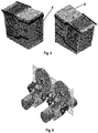
Fig 8 shows a winch according to one embodiment of the present invention; -
Fig 9 shows a winch according to the embodiment infigure 8 seen from another angle; - ;
-
Fig. 10 shows emergency operations, and -
Fig. 11 shows the ranking of the safety system. - In the following discussion it will be adhered to the accompanying drawings; however the drawings are not necessarily to scale nor are all features shown in the drawings mandatory, also some of the features may be excluded. The drawings are meant to ease understanding of the present invention.
- In the following discussion the following word may be used interchangeably; sheaves and pulleys, operators house, operators cabin, crane cabin, crane house; boom cylinders and hydraulic cylinders
- A crane system basically consists of the following main components:
-
- Provides foundation and routing for
winches 5 and serves as the interface towards the ship. It consists of a pedestal, slewing bearing,tower 2,booms cabin 4. -
- Lift and lower payloads.
-
- Provide hydraulic power to consumers fitted on the crane.
-
- Storing and releasing energy in combination with the hydraulic power unit.
-
- Station for normal operation of the crane.
- The ship delivers electric power supply to the crane. According to one embodiment of the invention the operation of the crane is electro hydraulic (hybrid system) and the hydraulic system is independent of any external to the crane hydraulic system i.e. being a self contained system. This provides for a neat and simple interface between the crane and the deck to which the crane is mounted. At least one electric pump builds up the pressure for the hydraulic system; the hydraulic system also includes a reservoir for the hydraulic fluid.
- The idea of an electro hydraulic system is that the "heavy work" is carried out by the hydraulics whilst acceleration and fine movements are controlled and carried out by electric motors/actuators. Further description of the electro hydraulic system, the hydraulic system, the electric system and control thereof is described below.
- A
tower 2 is a tubular shaped member which is at its lower end arranged vertically on a pedestal. At its upper end anoperator cabin 4 is fixed to thetower 2. Amachine house 3 is arranged adjacent to theoperator cabin 4. According to a first embodiment of the invention awinch 5 is rotatably arranged between two support plates +which extend out from an upper side of thetower 2 opposite of amain boom 14. Thewinch 5 is of an electro hydraulic type, thus heave compensation and movements with high acceleration are carried out by the electric motor internal of the winch whereas the movements with low acceleration are controlled by hydraulic motors. - In a second embodiment the winch is arranged external to the crane and a sheave is arranged where the
winch 5 is arranged in the first embodiment of the invention described above. - The crane control system is based on an Industrial Controller (IC), control cabinets and sensors. The IC reads physical parameters such as boom angles, wire length on winch and crane load. The parameters are provided by sensors.
- Crane functions are controlled by joysticks, switches and an operator panel inside the
cabin 4. The joysticks control thewinch 5, slew andbooms - All sensor signals are routed to the industrial controller. Based on these signals the IC controls the crane, evaluates safety measures, activates alarms and presents necessary information on an operator display in the
cabin 4. - The actual working radius and allowable safe working load (SWL) are calculated in the control system, these values are presented in the operator display. The operator is naturally responsible for safe operation of the crane, but the calculated values are also used as a safety measure to reduce the boom speeds in the end-positions for the
boom cylinders - The load measurement is performed by a load cell bolt, mounted in the
wire sheave 10 at the second end of the knuckle boom. The load cell amplifier gives an analogue input signal to the IC. - On the HPU several sensors/transmitters are installed, feedback on temperature, pressure from each pump and filter indication is available for the operator at all times. For instance are high oil temperature alarms and start / stop of oil coolers controlled by the IC-based on the input from the temperature transmitter on the HPU.
- Encoders control the hook stop function of the
winches 5. The encoder signals are input to the IC, which counts pulses from the sensors and also detect the direction of the motion. Via the operator display it is possible to reset the counting to zero and set span for the motion. The display will continuously show the actual wire paid out on the winch (from hook stop upper position). - The Motion Reference Unit, MRU, measures the vessels movements (roll, pitch, heave and heave acceleration). Based on the MRU signals and the crane position related to the vessel, the IC calculates the actual movement of the boom tip/second end of
knuckle boom 12. During active heave compensation the MRU generates a reference/feedback signal to the control system in order to compensate for the boom tip movement. - Depending on the task to be performed, the operator can select the required system mode. Please note that the control system, under certain conditions, automatically will select one of the below modes.
- The
main winch 5 can change between the modes shown in thefigure 4 . Arrows indicate possible transitions.Table 1 Standby This is the default mode for the winch 5 when the control system is ONNormal In this mode the winch 5 is run from the joystick, the brakes are engaged during deck lift and disengaged during subsea lift.AHC This mode is used to compensate the ship movement caused by waves. AHC operation mode will keep the distance between the seabed and load constant. The AHC controller gets its set point from a MRU. The joystick may be used to both hoist and lower the payload while in AHC, but the sum of speed signals will never exceed the winch capacity. CT In this mode the unit gets its speed set point from a Constant Tension controller detecting rope tension variations, thereby keeping the rope tension near constant. The set point may be changed by the operator at any time. Detection of rope tension is carried out by a sensor. AOPS Automatic overload protection system (see safety functions for details) MOPS Manual overload protection system (see safety functions for details) Error Fault in the system, as example drive unit error, software communication failure or load drop. -
Table 2 Normal crane operation Functions Slewing (joysticks on operators chair) Main boom 14Knuckle boom 12Main winch 5Armrest / operator panel Instrumentation / activators Emergency stop System on/off Joystick on/off MOPS main winch Emergency operation (emergency panel) Functions Slewing Main boom Knuckle boom Main winch - The operational chair is according to one embodiment equipped with a joystick on each armrest, in addition there can be display with graphical user interface were system components can be selected. Each main component can be provided with its own page on the GUI were required information is available. Obviously other design with joysticks arranged on a pad with a gooseneck which facilitates movement of the pad is an alternative design. The GUI is microprocessor controlled hence the GUI scales well and it might be upgraded and reprogrammed. In one embodiment the armrest controls on the operators chair are:
-
- Main winch (Y-axis)
- Elbow boom (X-axis)
- Speaker (push button).
-
- Main boom (Y-axis)
- Slewing (X-axis)
- Horn (push button).
- All joysticks may have two axes with spring return to zero. The operational speed is proportional to the handle movement but it is limited by the control system to give approximately constant power.
- The operator display provides interaction between the operator and the control system in order to assure safe operation of the crane in all modes. From the GUI, different systems components can be selected. These system components have a common GUI platform and the alternative window based screen images are of similar design.
-
- Component selection
- Mode selection
- ∘ Type of lift (Internal/Harbour lift, external)
- ∘ AHC
- ∘ CT
- ∘ Ship to ship
- Load indication with allowable load / radius information.
- Sub component info
- ∘ Drive unit
- ∘ Brakes
- ∘ Hydraulic pressure and temperature
- ∘ Filter status.
- An operator panel can be located next to the operator's chair. The operator's panel contains buttons and switches for safety measures and operation of auxiliary equipment such as window wipers and washer, stereo and optionally for UHF/VHF.
- Main equipment / functions:
- Emergency stop
- Mushroom type push button.
- ∘ MOPS main winch
- Push button w/cover to avoid unintended activation.
- ∘ Key switch, handling of personnel Off/On
- ∘ Key switch, system Off/On
- ∘ Key switch, joystick Off/On
- There are two types of emergency operation panels on this crane. One type for operating the crane and winches, the other is emergency start/stop of the pumps on the HPU. The activators for emergency start/stop of HPU are located on the starter cabinets.
- The emergency operation panel and its base unit are located in the
operator cabin 4. There is one common panel for operation of all the crane functions. - The emergency operation panel is portable and it is equipped with a cable for connection to the base unit. As there is no emergency stop button on the panel, it must be used within immediate reach of one. It is recommended that the emergency operation panel is used while seated in the operator chair.
- The handles on the emergency operation panel is "hold to run" type and their function is clearly marked.
-
Table 3 Main winch MOPS, Manual overload protection The system can be activated at all time and at any configuration, including after emergency stop and power failure. When activated the system will maintain a retaining force of approx. 20% of maximum rated capacity. All other functions are overridden during activation. The valves to be activated are powered by UPS. Fail safe brake The Fail-Safe brakes are spring applied and hydraulic released, this means that it starts to brake when the oil pressure to the brake disappears. As this system is fitted with handling of personnel the winch has two independent brakes, one on the winch drives and one directly on the drum. AOPS, Automatic overload protection The system continuously monitors the loads and load moment on the crane. Load increasing above the set point for activation will make the winch pay out automatically to avoid damage to the crane and its components Motion limiter An encoder is fitted to calculate the actual hook position. End stop is programmed in upper position and a bitter end is set (5 turns left with wire on the drum) Crane Main boom / knuckle boom Load holding valve and sensors for reduction of speed at end positions. Slewing Load holding valve and fail safe brake Hydraulic system Relief valves All hydraulic pressure lines are equipped with relief valves to prevent excessive pressure in the system. Electric system Overload protection The system is equipped with circuit breakers and the frequency drive has internal safety measures in case of over current, hot motor, communication error etc. Complete system Emergency stop When activated the unit will stop. (Hydraulic and electric energy will be cut off). Note: control system will still be operational. - In
figure 11 the order of precedence of the safety measures are shown. In case of conflicting functions the measures at a higher level shall have priority. Emergency stop / MOPS shall have equal priority. - The crane can be designed as a self-contained unit without any hydraulic interface to the vessel.
- Hydraulic power unit, drives and accumulator system which is dimensioned to allow operation at nominal speed and AHC capacities in accordance with industry standard regulations.
- The hydraulic system basically consist of the following components Hydraulic power unit (HPU)
- Provides hydraulic energy to the different consumers. It stores, cools and filtrates the hydraulic oil in the system.
-
- The hydraulic accumulator is a storage reservoir in which a non-compressible hydraulic fluid is held under pressure by nitrogen. The main reasons for use of accumulators in the hydraulic system are to reduce the size of the pump without reducing capacity during extremes of demand. It also aids the supply circuit to respond quickly to any temporary demand and to smooth pulsations in the system.
-
- Consumer of hydraulic oil such as a
winch 5, slewing gear or luffing cylinders. -
- The hydraulic manifold is a component which regulates fluid flow between pumps and actuators and other components in a hydraulic system. It is like a switchboard in an electrical circuit because it lets the operator control how much fluid flows between which components of a hydraulic machinery.
-
- This includes pipes
- A combination of hydraulic and electrical motors is according to one embodiment provided for operation of the machinery.
- In one example of design the
winch 5 is a 150 Te winch for crane: - With at least one electrical motors (approx 500 kW each)
- At least one hydraulic motor such as Variable displacement hydraulic motor A6VM 1000 cm3.
- The number and combinations off drive units will vary depending on size and requirements for the equipment it is installed on.
- The hydraulic motors are mainly for load holding while the electric motors provide speed and acceleration.
- Electrical power can be regenerated to the vessel.
- Flexible solution with regards to available speed at different loads.
- Reduced complexity on hydraulic power unit.
- Reduced complexity on hydraulic motors.
- Reduced installation time.
- The electro installation is completed on the crane, ready for termination on the slip ring in the pedestal. The slip ring is a typical electric interface to the ship.
Table 4 Power section Item no Description Voltage (AC) Power (kW) Comment 1 2 x main pump motors 690V / 60 Hz 260 kW S1-100% 2 2 x aux pump motors 690V / 60 Hz 18 kW S1-100% 3 1 x filtration unit pump motor 690V / 60 Hz 15 kW S1-100% 4 2 x cooler motors (return oil) 690V / 60 Hz 10 kW S1-100% 5 1 x cooler motors (gear) 690V / 60 Hz 3.5 kW S1-100% 6 1 x ventilation motor 690V / 60 Hz 6 kW S1-100% 7 1 x Emergency motor 690V / 60 Hz 45 kW S1-100% 8 1 x Ground / PE 9 Control system supply 230V / 60 Hz (conn. to vessel UPS) 10 Lights and heating 230V / 60 Hz 11 Spare 230V / 60 Hz - A manually operated emergency stop system, leading to shut-down and stop of the crane movements is fitted. Simultaneously, the brakes are engaged in a progressive and safe manner. The emergency stop maintains its function regardless of any fault in the control system.
- Emergency stop actuators are located at convenient locations for immediate use:
- One inside
crane cabin 4. - One inside
tower 2. - One outside of the pedestal (deck level).
- One on the HPU starter cabinet door (in machinery house 3)
- The arrangement of the emergency stop system is designed so that no single failure will cause loss of duplicated essential or important equipment.
- In one embodiment the wire to be used is compact and rotation resistant. • The slewing speed is reduced at high loads.
AHC Active heave compensation HPU Hydraulic power unit IC Industrial Controller SWL safe working load MRU Motion Reference Unit ROV Remotely operated vehicle GUI Graphical user interface
Claims (9)
- A hybrid drive wire winch (5) adapted for operation with a knuckle boom crane, where the hybrid drive wire winch (5) at least comprises:a) at least one electric motor and at least one hydraulic motor for operation of the winch;b) a control system;c) a frequency converter for speed and directional adjustment of the at least one electric motor and;d) a hydraulic power unit in operational engagement with a directional valve, where the directional valve controls the rotary direction of the winch (5).
- A hybrid drive wire winch (5) according to claim 1, where the control system is configured to provide automatic heave compensation signals to the frequency controller and the hydraulic power unit so as to provide for an active heave compensated winch (5).
- A hybrid drive wire winch (5) according to claim 1 or 2, where the hybrid drive wire winch (5) further comprises a manual overload protection.
- A hybrid drive wire winch (5) and a hybrid drive for the wire winch according to any of the previous claims, where the hybrid drive wire winch further comprises fail safe brakes.
- A hybrid drive wire winch (5) according to claim 4, where the fail safe brakes are spring applied and hydraulic released.
- A hybrid drive wire winch (5) according to claim 5, where the fail safe brakes are provided as two independent brakes, one on the hybrid drive wire winch (5) drives and one directly on the drum.
- A hybrid drive wire winch (5) according to any of the previous claims, where the hybrid drive wire winch (5) further comprises a motion limiter.
- A hybrid drive wire winch (5) assembly according to claim 7, where the motion limiter is provided as an encoder for calculation of an actual hook position.
- A hybrid drive wire winch (5) according to any of the previous claims where the frequency converter further is connected to the control system and to a second electric motor, where the second electric motor is in operational engagement with a variable hydraulic displacement pump, the hydraulic power unit includes the variable hydraulic displacement pump and the second motor.
Priority Applications (1)
| Application Number | Priority Date | Filing Date | Title |
|---|---|---|---|
| PL16200012T PL3153397T3 (en) | 2012-06-06 | 2013-06-06 | A hybrid wire winch |
Applications Claiming Priority (3)
| Application Number | Priority Date | Filing Date | Title |
|---|---|---|---|
| US201261656098P | 2012-06-06 | 2012-06-06 | |
| EP13886748.6A EP2858889B1 (en) | 2012-06-06 | 2013-06-06 | Hybrid crane |
| PCT/NO2013/050101 WO2014200354A1 (en) | 2012-06-06 | 2013-06-06 | Hybrid crane |
Related Parent Applications (2)
| Application Number | Title | Priority Date | Filing Date |
|---|---|---|---|
| EP13886748.6A Division-Into EP2858889B1 (en) | 2012-06-06 | 2013-06-06 | Hybrid crane |
| EP13886748.6A Division EP2858889B1 (en) | 2012-06-06 | 2013-06-06 | Hybrid crane |
Publications (2)
| Publication Number | Publication Date |
|---|---|
| EP3153397A1 true EP3153397A1 (en) | 2017-04-12 |
| EP3153397B1 EP3153397B1 (en) | 2018-12-12 |
Family
ID=52022526
Family Applications (3)
| Application Number | Title | Priority Date | Filing Date |
|---|---|---|---|
| EP13886748.6A Active EP2858889B1 (en) | 2012-06-06 | 2013-06-06 | Hybrid crane |
| EP16199995.8A Active EP3153396B1 (en) | 2012-06-06 | 2013-06-06 | A main boom and a knuckle boom |
| EP16200012.9A Active EP3153397B1 (en) | 2012-06-06 | 2013-06-06 | A hybrid wire winch |
Family Applications Before (2)
| Application Number | Title | Priority Date | Filing Date |
|---|---|---|---|
| EP13886748.6A Active EP2858889B1 (en) | 2012-06-06 | 2013-06-06 | Hybrid crane |
| EP16199995.8A Active EP3153396B1 (en) | 2012-06-06 | 2013-06-06 | A main boom and a knuckle boom |
Country Status (7)
| Country | Link |
|---|---|
| US (1) | US10259692B2 (en) |
| EP (3) | EP2858889B1 (en) |
| BR (1) | BR112014030447B1 (en) |
| MX (1) | MX357680B (en) |
| NO (1) | NO2948365T3 (en) |
| PL (3) | PL3153396T3 (en) |
| WO (1) | WO2014200354A1 (en) |
Cited By (1)
| Publication number | Priority date | Publication date | Assignee | Title |
|---|---|---|---|---|
| US11894788B2 (en) | 2020-11-04 | 2024-02-06 | Builtrite, LLC | Variable frequency drive electric hydraulic material handler |
Families Citing this family (21)
| Publication number | Priority date | Publication date | Assignee | Title |
|---|---|---|---|---|
| DK178120B1 (en) * | 2013-04-18 | 2015-06-01 | A P Møller Mærsk As | An Offshore Floating Vessel and a Method of Operating the Same |
| NO343495B1 (en) | 2015-07-14 | 2019-03-25 | Mhwirth As | A hybrid winch system |
| US9790070B2 (en) * | 2015-11-03 | 2017-10-17 | Cameron International Corporation | Rope hoisting system |
| NL2016444B1 (en) * | 2016-03-04 | 2017-09-19 | U-Sea Beheer B V | Disturbance compensating telescopic knuckle boom crane, ship provided therewith and method therefor |
| NO20160977A1 (en) * | 2016-06-07 | 2017-11-06 | Rolls Royce Marine As | Knuckle boom crane |
| EP3318530B1 (en) * | 2016-11-03 | 2020-04-01 | National Oilwell Varco Norway AS | Method of upgrading a knuckle-boom crane and a heave-compensating crane |
| CN110382346B (en) * | 2017-01-16 | 2021-10-01 | 伊特里克公司 | Deep water lifting system and method |
| NO343566B1 (en) * | 2017-05-16 | 2019-04-08 | Kvaerner As | Low build electric luffing crane |
| CN108163725B (en) * | 2018-03-19 | 2019-06-28 | 中国能源建设集团东北电力第二工程有限公司 | A kind of power equipment hanging apparatus folded convenient for storage |
| NL2020664B1 (en) * | 2018-03-26 | 2019-10-07 | Barge Master Ip B V | Offshore crane |
| US11014791B2 (en) * | 2018-04-05 | 2021-05-25 | Vermeer Manufacturing Company | Self-raising winch boom and control systems and methods associated therewith |
| US10766579B1 (en) * | 2018-04-09 | 2020-09-08 | The United States Of America As Represented By The Secretary Of The Navy | Passive heave compensated davit |
| EP3956974A1 (en) * | 2019-04-17 | 2022-02-23 | MetisMotion GmbH | Stroke transmitter for an actuator device |
| US11235957B2 (en) * | 2019-08-23 | 2022-02-01 | Oceaneering International, Inc. | Motion arresting and dampening device |
| FR3105200B1 (en) | 2019-12-24 | 2021-12-03 | Reel | Knuckle boom crane, for offshore application |
| EP4008679B1 (en) * | 2020-12-03 | 2024-10-23 | Reel | Articulated boom crane, for offshore application |
| FR3117099B1 (en) * | 2020-12-03 | 2022-11-25 | Reel | Articulated jib crane, for offshore application |
| NO348348B1 (en) * | 2021-06-11 | 2024-12-02 | Seaonics As | A crane for a ship |
| CN114104995B (en) * | 2021-11-17 | 2024-07-30 | 大连海事大学 | A movable ring-track type tandem mechanical arm anti-sway device |
| US12091138B1 (en) | 2023-03-14 | 2024-09-17 | Ralph E. Matlack | Ammonia bunker delivery system for transferring of ammonia bunker fuel |
| CN116588819A (en) * | 2023-04-26 | 2023-08-15 | 中国一冶集团有限公司 | A hoisting device for a glass curtain wall plate and its construction method |
Citations (2)
| Publication number | Priority date | Publication date | Assignee | Title |
|---|---|---|---|---|
| WO2006008052A1 (en) * | 2004-07-19 | 2006-01-26 | Bosch Rexroth Ag | Winch |
| WO2009036456A2 (en) * | 2007-09-14 | 2009-03-19 | Goodcrane Corporation | Motion compensation system |
Family Cites Families (14)
| Publication number | Priority date | Publication date | Assignee | Title |
|---|---|---|---|---|
| US3117686A (en) * | 1960-08-01 | 1964-01-14 | American Hoist & Derrick Co | Back hoe excavator |
| US3279632A (en) * | 1964-11-27 | 1966-10-18 | Lorenz H Kramlich | Back hoe excavator |
| GB1529331A (en) | 1976-03-02 | 1978-10-18 | Clarke Chapman Ltd | Winding mechanism |
| JPS5939015B2 (en) * | 1981-12-18 | 1984-09-20 | 近畿イシコ株式会社 | Lifting method using a hydraulic excavator |
| KR100294480B1 (en) * | 1996-06-04 | 2001-09-17 | 세구치 류이치 | Operator attachment machine |
| DE20005890U1 (en) * | 2000-03-30 | 2000-08-24 | Haas, Franz-Alfred, 87541 Hindelang | Winch construction |
| EP1477450B1 (en) | 2003-04-30 | 2006-09-06 | Hiab Ab | A crane |
| AT10273U1 (en) | 2007-05-03 | 2008-12-15 | Palfinger Ag | ADJUSTMENT MECHANISM FOR A WINCH |
| US8783478B2 (en) * | 2007-10-11 | 2014-07-22 | Itrec B.V. | Hoisting crane and offshore vessel |
| NO333202B1 (en) | 2009-02-16 | 2013-04-08 | Nat Oilwell Varco Norway As | Method and apparatus for hoisting a package from a crane |
| KR101115367B1 (en) * | 2010-05-13 | 2012-02-15 | (주)엠씨티이엔지 | Oscillation Compensation Device for Knuckle Crane for Offshore Ships |
| KR101027583B1 (en) * | 2010-07-08 | 2011-04-06 | (주)해안기계산업 | Vertical swing compensation system for ship crane |
| NO336245B1 (en) * | 2010-09-21 | 2015-06-29 | Rolls Royce Marine As | HIV compensated crane |
| US8863966B2 (en) * | 2011-03-21 | 2014-10-21 | Dynaking Crane, Llc | Kingpost crane apparatus and method |
-
2013
- 2013-06-06 MX MX2014014939A patent/MX357680B/en active IP Right Grant
- 2013-06-06 EP EP13886748.6A patent/EP2858889B1/en active Active
- 2013-06-06 EP EP16199995.8A patent/EP3153396B1/en active Active
- 2013-06-06 WO PCT/NO2013/050101 patent/WO2014200354A1/en not_active Ceased
- 2013-06-06 US US14/405,829 patent/US10259692B2/en active Active
- 2013-06-06 PL PL16199995T patent/PL3153396T3/en unknown
- 2013-06-06 BR BR112014030447-5A patent/BR112014030447B1/en active IP Right Grant
- 2013-06-06 PL PL16200012T patent/PL3153397T3/en unknown
- 2013-06-06 EP EP16200012.9A patent/EP3153397B1/en active Active
- 2013-06-06 PL PL13886748T patent/PL2858889T3/en unknown
-
2014
- 2014-01-27 NO NO14743759A patent/NO2948365T3/no unknown
Patent Citations (2)
| Publication number | Priority date | Publication date | Assignee | Title |
|---|---|---|---|---|
| WO2006008052A1 (en) * | 2004-07-19 | 2006-01-26 | Bosch Rexroth Ag | Winch |
| WO2009036456A2 (en) * | 2007-09-14 | 2009-03-19 | Goodcrane Corporation | Motion compensation system |
Cited By (1)
| Publication number | Priority date | Publication date | Assignee | Title |
|---|---|---|---|---|
| US11894788B2 (en) | 2020-11-04 | 2024-02-06 | Builtrite, LLC | Variable frequency drive electric hydraulic material handler |
Also Published As
| Publication number | Publication date |
|---|---|
| BR112014030447B1 (en) | 2022-04-19 |
| EP2858889B1 (en) | 2017-08-09 |
| MX2014014939A (en) | 2015-07-09 |
| NO2948365T3 (en) | 2018-05-19 |
| EP3153396A1 (en) | 2017-04-12 |
| PL3153397T3 (en) | 2019-07-31 |
| EP2858889A1 (en) | 2015-04-15 |
| EP3153396B1 (en) | 2018-12-26 |
| EP2858889A4 (en) | 2016-05-11 |
| WO2014200354A1 (en) | 2014-12-18 |
| BR112014030447A2 (en) | 2017-08-22 |
| US20160152451A1 (en) | 2016-06-02 |
| US10259692B2 (en) | 2019-04-16 |
| EP3153397B1 (en) | 2018-12-12 |
| PL3153396T3 (en) | 2019-07-31 |
| PL2858889T3 (en) | 2018-03-30 |
| MX357680B (en) | 2018-07-19 |
Similar Documents
| Publication | Publication Date | Title |
|---|---|---|
| EP3153397B1 (en) | A hybrid wire winch | |
| US20220203146A1 (en) | Personal safety apparatus and system | |
| CN112224344B (en) | Submersible lifting system | |
| EP1914191B1 (en) | Hoisting crane and offshore vessel | |
| US8160786B2 (en) | Mobile crane and method for operating a mobile crane | |
| CA2504749C (en) | Electric winch | |
| US7490728B2 (en) | Crane | |
| EP2526042A1 (en) | A method for controlling the orientation of a load suspended from a bearing wire about said bearing wire and a winch arrangement | |
| US20070098504A1 (en) | Offshore Vessel | |
| JP2017186155A (en) | crane | |
| JP2018083713A (en) | Irregular winding preventing device for winch and crane | |
| WO2017216944A1 (en) | Mobile crane | |
| CN213735444U (en) | Submersible lifting system | |
| US10787345B2 (en) | Crane | |
| JP2673437B2 (en) | Operating device for cranes | |
| CN210559058U (en) | Wind power platform anchor mooring remote control system | |
| JP5156469B2 (en) | Winch equipment | |
| US11053100B1 (en) | Crane winch assembly stowage and mode detection system and method | |
| JP2021075918A (en) | Safety system for pile driver | |
| JPH1192098A (en) | Crane truck combined with aerial work vehicle | |
| CN115924773A (en) | A cable wind winch | |
| KR970007460B1 (en) | Hydraulic winch with remote control |
Legal Events
| Date | Code | Title | Description |
|---|---|---|---|
| PUAI | Public reference made under article 153(3) epc to a published international application that has entered the european phase |
Free format text: ORIGINAL CODE: 0009012 |
|
| STAA | Information on the status of an ep patent application or granted ep patent |
Free format text: STATUS: REQUEST FOR EXAMINATION WAS MADE |
|
| 17P | Request for examination filed |
Effective date: 20161124 |
|
| AC | Divisional application: reference to earlier application |
Ref document number: 2858889 Country of ref document: EP Kind code of ref document: P |
|
| AK | Designated contracting states |
Kind code of ref document: A1 Designated state(s): AL AT BE BG CH CY CZ DE DK EE ES FI FR GB GR HR HU IE IS IT LI LT LU LV MC MK MT NL NO PL PT RO RS SE SI SK SM TR |
|
| GRAP | Despatch of communication of intention to grant a patent |
Free format text: ORIGINAL CODE: EPIDOSNIGR1 |
|
| STAA | Information on the status of an ep patent application or granted ep patent |
Free format text: STATUS: GRANT OF PATENT IS INTENDED |
|
| INTG | Intention to grant announced |
Effective date: 20180711 |
|
| GRAS | Grant fee paid |
Free format text: ORIGINAL CODE: EPIDOSNIGR3 |
|
| GRAA | (expected) grant |
Free format text: ORIGINAL CODE: 0009210 |
|
| STAA | Information on the status of an ep patent application or granted ep patent |
Free format text: STATUS: THE PATENT HAS BEEN GRANTED |
|
| AC | Divisional application: reference to earlier application |
Ref document number: 2858889 Country of ref document: EP Kind code of ref document: P |
|
| AK | Designated contracting states |
Kind code of ref document: B1 Designated state(s): AL AT BE BG CH CY CZ DE DK EE ES FI FR GB GR HR HU IE IS IT LI LT LU LV MC MK MT NL NO PL PT RO RS SE SI SK SM TR |
|
| REG | Reference to a national code |
Ref country code: GB Ref legal event code: FG4D |
|
| REG | Reference to a national code |
Ref country code: CH Ref legal event code: EP |
|
| REG | Reference to a national code |
Ref country code: AT Ref legal event code: REF Ref document number: 1075611 Country of ref document: AT Kind code of ref document: T Effective date: 20181215 |
|
| REG | Reference to a national code |
Ref country code: DE Ref legal event code: R096 Ref document number: 602013048289 Country of ref document: DE |
|
| REG | Reference to a national code |
Ref country code: IE Ref legal event code: FG4D |
|
| REG | Reference to a national code |
Ref country code: NL Ref legal event code: FP |
|
| REG | Reference to a national code |
Ref country code: LT Ref legal event code: MG4D |
|
| PG25 | Lapsed in a contracting state [announced via postgrant information from national office to epo] |
Ref country code: FI Free format text: LAPSE BECAUSE OF FAILURE TO SUBMIT A TRANSLATION OF THE DESCRIPTION OR TO PAY THE FEE WITHIN THE PRESCRIBED TIME-LIMIT Effective date: 20181212 Ref country code: HR Free format text: LAPSE BECAUSE OF FAILURE TO SUBMIT A TRANSLATION OF THE DESCRIPTION OR TO PAY THE FEE WITHIN THE PRESCRIBED TIME-LIMIT Effective date: 20181212 Ref country code: LT Free format text: LAPSE BECAUSE OF FAILURE TO SUBMIT A TRANSLATION OF THE DESCRIPTION OR TO PAY THE FEE WITHIN THE PRESCRIBED TIME-LIMIT Effective date: 20181212 Ref country code: LV Free format text: LAPSE BECAUSE OF FAILURE TO SUBMIT A TRANSLATION OF THE DESCRIPTION OR TO PAY THE FEE WITHIN THE PRESCRIBED TIME-LIMIT Effective date: 20181212 Ref country code: ES Free format text: LAPSE BECAUSE OF FAILURE TO SUBMIT A TRANSLATION OF THE DESCRIPTION OR TO PAY THE FEE WITHIN THE PRESCRIBED TIME-LIMIT Effective date: 20181212 Ref country code: BG Free format text: LAPSE BECAUSE OF FAILURE TO SUBMIT A TRANSLATION OF THE DESCRIPTION OR TO PAY THE FEE WITHIN THE PRESCRIBED TIME-LIMIT Effective date: 20190312 |
|
| REG | Reference to a national code |
Ref country code: NO Ref legal event code: T2 Effective date: 20181212 |
|
| REG | Reference to a national code |
Ref country code: AT Ref legal event code: MK05 Ref document number: 1075611 Country of ref document: AT Kind code of ref document: T Effective date: 20181212 |
|
| PG25 | Lapsed in a contracting state [announced via postgrant information from national office to epo] |
Ref country code: AL Free format text: LAPSE BECAUSE OF FAILURE TO SUBMIT A TRANSLATION OF THE DESCRIPTION OR TO PAY THE FEE WITHIN THE PRESCRIBED TIME-LIMIT Effective date: 20181212 Ref country code: SE Free format text: LAPSE BECAUSE OF FAILURE TO SUBMIT A TRANSLATION OF THE DESCRIPTION OR TO PAY THE FEE WITHIN THE PRESCRIBED TIME-LIMIT Effective date: 20181212 Ref country code: GR Free format text: LAPSE BECAUSE OF FAILURE TO SUBMIT A TRANSLATION OF THE DESCRIPTION OR TO PAY THE FEE WITHIN THE PRESCRIBED TIME-LIMIT Effective date: 20190313 Ref country code: RS Free format text: LAPSE BECAUSE OF FAILURE TO SUBMIT A TRANSLATION OF THE DESCRIPTION OR TO PAY THE FEE WITHIN THE PRESCRIBED TIME-LIMIT Effective date: 20181212 |
|
| PG25 | Lapsed in a contracting state [announced via postgrant information from national office to epo] |
Ref country code: CZ Free format text: LAPSE BECAUSE OF FAILURE TO SUBMIT A TRANSLATION OF THE DESCRIPTION OR TO PAY THE FEE WITHIN THE PRESCRIBED TIME-LIMIT Effective date: 20181212 Ref country code: PT Free format text: LAPSE BECAUSE OF FAILURE TO SUBMIT A TRANSLATION OF THE DESCRIPTION OR TO PAY THE FEE WITHIN THE PRESCRIBED TIME-LIMIT Effective date: 20190412 Ref country code: IT Free format text: LAPSE BECAUSE OF FAILURE TO SUBMIT A TRANSLATION OF THE DESCRIPTION OR TO PAY THE FEE WITHIN THE PRESCRIBED TIME-LIMIT Effective date: 20181212 |
|
| PG25 | Lapsed in a contracting state [announced via postgrant information from national office to epo] |
Ref country code: EE Free format text: LAPSE BECAUSE OF FAILURE TO SUBMIT A TRANSLATION OF THE DESCRIPTION OR TO PAY THE FEE WITHIN THE PRESCRIBED TIME-LIMIT Effective date: 20181212 Ref country code: IS Free format text: LAPSE BECAUSE OF FAILURE TO SUBMIT A TRANSLATION OF THE DESCRIPTION OR TO PAY THE FEE WITHIN THE PRESCRIBED TIME-LIMIT Effective date: 20190412 Ref country code: SM Free format text: LAPSE BECAUSE OF FAILURE TO SUBMIT A TRANSLATION OF THE DESCRIPTION OR TO PAY THE FEE WITHIN THE PRESCRIBED TIME-LIMIT Effective date: 20181212 Ref country code: RO Free format text: LAPSE BECAUSE OF FAILURE TO SUBMIT A TRANSLATION OF THE DESCRIPTION OR TO PAY THE FEE WITHIN THE PRESCRIBED TIME-LIMIT Effective date: 20181212 Ref country code: SK Free format text: LAPSE BECAUSE OF FAILURE TO SUBMIT A TRANSLATION OF THE DESCRIPTION OR TO PAY THE FEE WITHIN THE PRESCRIBED TIME-LIMIT Effective date: 20181212 |
|
| REG | Reference to a national code |
Ref country code: DE Ref legal event code: R097 Ref document number: 602013048289 Country of ref document: DE |
|
| PLBE | No opposition filed within time limit |
Free format text: ORIGINAL CODE: 0009261 |
|
| STAA | Information on the status of an ep patent application or granted ep patent |
Free format text: STATUS: NO OPPOSITION FILED WITHIN TIME LIMIT |
|
| PG25 | Lapsed in a contracting state [announced via postgrant information from national office to epo] |
Ref country code: DK Free format text: LAPSE BECAUSE OF FAILURE TO SUBMIT A TRANSLATION OF THE DESCRIPTION OR TO PAY THE FEE WITHIN THE PRESCRIBED TIME-LIMIT Effective date: 20181212 Ref country code: AT Free format text: LAPSE BECAUSE OF FAILURE TO SUBMIT A TRANSLATION OF THE DESCRIPTION OR TO PAY THE FEE WITHIN THE PRESCRIBED TIME-LIMIT Effective date: 20181212 Ref country code: SI Free format text: LAPSE BECAUSE OF FAILURE TO SUBMIT A TRANSLATION OF THE DESCRIPTION OR TO PAY THE FEE WITHIN THE PRESCRIBED TIME-LIMIT Effective date: 20181212 |
|
| 26N | No opposition filed |
Effective date: 20190913 |
|
| PG25 | Lapsed in a contracting state [announced via postgrant information from national office to epo] |
Ref country code: MC Free format text: LAPSE BECAUSE OF FAILURE TO SUBMIT A TRANSLATION OF THE DESCRIPTION OR TO PAY THE FEE WITHIN THE PRESCRIBED TIME-LIMIT Effective date: 20181212 |
|
| REG | Reference to a national code |
Ref country code: CH Ref legal event code: PL |
|
| REG | Reference to a national code |
Ref country code: BE Ref legal event code: MM Effective date: 20190630 |
|
| PG25 | Lapsed in a contracting state [announced via postgrant information from national office to epo] |
Ref country code: TR Free format text: LAPSE BECAUSE OF FAILURE TO SUBMIT A TRANSLATION OF THE DESCRIPTION OR TO PAY THE FEE WITHIN THE PRESCRIBED TIME-LIMIT Effective date: 20181212 |
|
| PG25 | Lapsed in a contracting state [announced via postgrant information from national office to epo] |
Ref country code: IE Free format text: LAPSE BECAUSE OF NON-PAYMENT OF DUE FEES Effective date: 20190606 |
|
| PG25 | Lapsed in a contracting state [announced via postgrant information from national office to epo] |
Ref country code: LU Free format text: LAPSE BECAUSE OF NON-PAYMENT OF DUE FEES Effective date: 20190606 Ref country code: BE Free format text: LAPSE BECAUSE OF NON-PAYMENT OF DUE FEES Effective date: 20190630 Ref country code: LI Free format text: LAPSE BECAUSE OF NON-PAYMENT OF DUE FEES Effective date: 20190630 Ref country code: CH Free format text: LAPSE BECAUSE OF NON-PAYMENT OF DUE FEES Effective date: 20190630 |
|
| PG25 | Lapsed in a contracting state [announced via postgrant information from national office to epo] |
Ref country code: FR Free format text: LAPSE BECAUSE OF NON-PAYMENT OF DUE FEES Effective date: 20190630 |
|
| PG25 | Lapsed in a contracting state [announced via postgrant information from national office to epo] |
Ref country code: PL Free format text: LAPSE BECAUSE OF NON-PAYMENT OF DUE FEES Effective date: 20190606 |
|
| PG25 | Lapsed in a contracting state [announced via postgrant information from national office to epo] |
Ref country code: CY Free format text: LAPSE BECAUSE OF FAILURE TO SUBMIT A TRANSLATION OF THE DESCRIPTION OR TO PAY THE FEE WITHIN THE PRESCRIBED TIME-LIMIT Effective date: 20181212 |
|
| PG25 | Lapsed in a contracting state [announced via postgrant information from national office to epo] |
Ref country code: HU Free format text: LAPSE BECAUSE OF FAILURE TO SUBMIT A TRANSLATION OF THE DESCRIPTION OR TO PAY THE FEE WITHIN THE PRESCRIBED TIME-LIMIT; INVALID AB INITIO Effective date: 20130606 Ref country code: MT Free format text: LAPSE BECAUSE OF FAILURE TO SUBMIT A TRANSLATION OF THE DESCRIPTION OR TO PAY THE FEE WITHIN THE PRESCRIBED TIME-LIMIT Effective date: 20181212 |
|
| PG25 | Lapsed in a contracting state [announced via postgrant information from national office to epo] |
Ref country code: MK Free format text: LAPSE BECAUSE OF FAILURE TO SUBMIT A TRANSLATION OF THE DESCRIPTION OR TO PAY THE FEE WITHIN THE PRESCRIBED TIME-LIMIT Effective date: 20181212 |
|
| PGFP | Annual fee paid to national office [announced via postgrant information from national office to epo] |
Ref country code: DE Payment date: 20250618 Year of fee payment: 13 |
|
| PGFP | Annual fee paid to national office [announced via postgrant information from national office to epo] |
Ref country code: GB Payment date: 20250618 Year of fee payment: 13 |
|
| PGFP | Annual fee paid to national office [announced via postgrant information from national office to epo] |
Ref country code: NO Payment date: 20250618 Year of fee payment: 13 |
|
| PGFP | Annual fee paid to national office [announced via postgrant information from national office to epo] |
Ref country code: NL Payment date: 20250618 Year of fee payment: 13 |