EP3153297A1 - Manufacturing apparatus for film of non-uniform thickness and manufacturing method for film of non-uniform thickness - Google Patents
Manufacturing apparatus for film of non-uniform thickness and manufacturing method for film of non-uniform thickness Download PDFInfo
- Publication number
- EP3153297A1 EP3153297A1 EP15803272.2A EP15803272A EP3153297A1 EP 3153297 A1 EP3153297 A1 EP 3153297A1 EP 15803272 A EP15803272 A EP 15803272A EP 3153297 A1 EP3153297 A1 EP 3153297A1
- Authority
- EP
- European Patent Office
- Prior art keywords
- roller
- manufacturing apparatus
- shaped portion
- truncated
- cone
- Prior art date
- Legal status (The legal status is an assumption and is not a legal conclusion. Google has not performed a legal analysis and makes no representation as to the accuracy of the status listed.)
- Granted
Links
Images



Classifications
-
- B—PERFORMING OPERATIONS; TRANSPORTING
- B29—WORKING OF PLASTICS; WORKING OF SUBSTANCES IN A PLASTIC STATE IN GENERAL
- B29C—SHAPING OR JOINING OF PLASTICS; SHAPING OF MATERIAL IN A PLASTIC STATE, NOT OTHERWISE PROVIDED FOR; AFTER-TREATMENT OF THE SHAPED PRODUCTS, e.g. REPAIRING
- B29C43/00—Compression moulding, i.e. applying external pressure to flow the moulding material; Apparatus therefor
- B29C43/32—Component parts, details or accessories; Auxiliary operations
- B29C43/44—Compression means for making articles of indefinite length
- B29C43/46—Rollers
-
- B—PERFORMING OPERATIONS; TRANSPORTING
- B29—WORKING OF PLASTICS; WORKING OF SUBSTANCES IN A PLASTIC STATE IN GENERAL
- B29C—SHAPING OR JOINING OF PLASTICS; SHAPING OF MATERIAL IN A PLASTIC STATE, NOT OTHERWISE PROVIDED FOR; AFTER-TREATMENT OF THE SHAPED PRODUCTS, e.g. REPAIRING
- B29C48/00—Extrusion moulding, i.e. expressing the moulding material through a die or nozzle which imparts the desired form; Apparatus therefor
- B29C48/001—Combinations of extrusion moulding with other shaping operations
- B29C48/0011—Combinations of extrusion moulding with other shaping operations combined with compression moulding
-
- B—PERFORMING OPERATIONS; TRANSPORTING
- B29—WORKING OF PLASTICS; WORKING OF SUBSTANCES IN A PLASTIC STATE IN GENERAL
- B29C—SHAPING OR JOINING OF PLASTICS; SHAPING OF MATERIAL IN A PLASTIC STATE, NOT OTHERWISE PROVIDED FOR; AFTER-TREATMENT OF THE SHAPED PRODUCTS, e.g. REPAIRING
- B29C48/00—Extrusion moulding, i.e. expressing the moulding material through a die or nozzle which imparts the desired form; Apparatus therefor
- B29C48/03—Extrusion moulding, i.e. expressing the moulding material through a die or nozzle which imparts the desired form; Apparatus therefor characterised by the shape of the extruded material at extrusion
- B29C48/07—Flat, e.g. panels
- B29C48/08—Flat, e.g. panels flexible, e.g. films
-
- B—PERFORMING OPERATIONS; TRANSPORTING
- B29—WORKING OF PLASTICS; WORKING OF SUBSTANCES IN A PLASTIC STATE IN GENERAL
- B29C—SHAPING OR JOINING OF PLASTICS; SHAPING OF MATERIAL IN A PLASTIC STATE, NOT OTHERWISE PROVIDED FOR; AFTER-TREATMENT OF THE SHAPED PRODUCTS, e.g. REPAIRING
- B29C48/00—Extrusion moulding, i.e. expressing the moulding material through a die or nozzle which imparts the desired form; Apparatus therefor
- B29C48/03—Extrusion moulding, i.e. expressing the moulding material through a die or nozzle which imparts the desired form; Apparatus therefor characterised by the shape of the extruded material at extrusion
- B29C48/12—Articles with an irregular circumference when viewed in cross-section, e.g. window profiles
-
- B—PERFORMING OPERATIONS; TRANSPORTING
- B29—WORKING OF PLASTICS; WORKING OF SUBSTANCES IN A PLASTIC STATE IN GENERAL
- B29C—SHAPING OR JOINING OF PLASTICS; SHAPING OF MATERIAL IN A PLASTIC STATE, NOT OTHERWISE PROVIDED FOR; AFTER-TREATMENT OF THE SHAPED PRODUCTS, e.g. REPAIRING
- B29C48/00—Extrusion moulding, i.e. expressing the moulding material through a die or nozzle which imparts the desired form; Apparatus therefor
- B29C48/25—Component parts, details or accessories; Auxiliary operations
- B29C48/30—Extrusion nozzles or dies
-
- B—PERFORMING OPERATIONS; TRANSPORTING
- B29—WORKING OF PLASTICS; WORKING OF SUBSTANCES IN A PLASTIC STATE IN GENERAL
- B29C—SHAPING OR JOINING OF PLASTICS; SHAPING OF MATERIAL IN A PLASTIC STATE, NOT OTHERWISE PROVIDED FOR; AFTER-TREATMENT OF THE SHAPED PRODUCTS, e.g. REPAIRING
- B29C48/00—Extrusion moulding, i.e. expressing the moulding material through a die or nozzle which imparts the desired form; Apparatus therefor
- B29C48/25—Component parts, details or accessories; Auxiliary operations
- B29C48/30—Extrusion nozzles or dies
- B29C48/305—Extrusion nozzles or dies having a wide opening, e.g. for forming sheets
-
- B—PERFORMING OPERATIONS; TRANSPORTING
- B29—WORKING OF PLASTICS; WORKING OF SUBSTANCES IN A PLASTIC STATE IN GENERAL
- B29C—SHAPING OR JOINING OF PLASTICS; SHAPING OF MATERIAL IN A PLASTIC STATE, NOT OTHERWISE PROVIDED FOR; AFTER-TREATMENT OF THE SHAPED PRODUCTS, e.g. REPAIRING
- B29C48/00—Extrusion moulding, i.e. expressing the moulding material through a die or nozzle which imparts the desired form; Apparatus therefor
- B29C48/25—Component parts, details or accessories; Auxiliary operations
- B29C48/30—Extrusion nozzles or dies
- B29C48/35—Extrusion nozzles or dies with rollers
-
- B—PERFORMING OPERATIONS; TRANSPORTING
- B29—WORKING OF PLASTICS; WORKING OF SUBSTANCES IN A PLASTIC STATE IN GENERAL
- B29C—SHAPING OR JOINING OF PLASTICS; SHAPING OF MATERIAL IN A PLASTIC STATE, NOT OTHERWISE PROVIDED FOR; AFTER-TREATMENT OF THE SHAPED PRODUCTS, e.g. REPAIRING
- B29C48/00—Extrusion moulding, i.e. expressing the moulding material through a die or nozzle which imparts the desired form; Apparatus therefor
- B29C48/25—Component parts, details or accessories; Auxiliary operations
- B29C48/88—Thermal treatment of the stream of extruded material, e.g. cooling
-
- B—PERFORMING OPERATIONS; TRANSPORTING
- B29—WORKING OF PLASTICS; WORKING OF SUBSTANCES IN A PLASTIC STATE IN GENERAL
- B29C—SHAPING OR JOINING OF PLASTICS; SHAPING OF MATERIAL IN A PLASTIC STATE, NOT OTHERWISE PROVIDED FOR; AFTER-TREATMENT OF THE SHAPED PRODUCTS, e.g. REPAIRING
- B29C48/00—Extrusion moulding, i.e. expressing the moulding material through a die or nozzle which imparts the desired form; Apparatus therefor
- B29C48/25—Component parts, details or accessories; Auxiliary operations
- B29C48/88—Thermal treatment of the stream of extruded material, e.g. cooling
- B29C48/90—Thermal treatment of the stream of extruded material, e.g. cooling with calibration or sizing, i.e. combined with fixing or setting of the final dimensions of the extruded article
-
- B—PERFORMING OPERATIONS; TRANSPORTING
- B29—WORKING OF PLASTICS; WORKING OF SUBSTANCES IN A PLASTIC STATE IN GENERAL
- B29C—SHAPING OR JOINING OF PLASTICS; SHAPING OF MATERIAL IN A PLASTIC STATE, NOT OTHERWISE PROVIDED FOR; AFTER-TREATMENT OF THE SHAPED PRODUCTS, e.g. REPAIRING
- B29C69/00—Combinations of shaping techniques not provided for in a single one of main groups B29C39/00 - B29C67/00, e.g. associations of moulding and joining techniques; Apparatus therefore
- B29C69/02—Combinations of shaping techniques not provided for in a single one of main groups B29C39/00 - B29C67/00, e.g. associations of moulding and joining techniques; Apparatus therefore of moulding techniques only
-
- B—PERFORMING OPERATIONS; TRANSPORTING
- B29—WORKING OF PLASTICS; WORKING OF SUBSTANCES IN A PLASTIC STATE IN GENERAL
- B29D—PRODUCING PARTICULAR ARTICLES FROM PLASTICS OR FROM SUBSTANCES IN A PLASTIC STATE
- B29D11/00—Producing optical elements, e.g. lenses or prisms
- B29D11/00663—Production of light guides
-
- F—MECHANICAL ENGINEERING; LIGHTING; HEATING; WEAPONS; BLASTING
- F21—LIGHTING
- F21K—NON-ELECTRIC LIGHT SOURCES USING LUMINESCENCE; LIGHT SOURCES USING ELECTROCHEMILUMINESCENCE; LIGHT SOURCES USING CHARGES OF COMBUSTIBLE MATERIAL; LIGHT SOURCES USING SEMICONDUCTOR DEVICES AS LIGHT-GENERATING ELEMENTS; LIGHT SOURCES NOT OTHERWISE PROVIDED FOR
- F21K2/00—Non-electric light sources using luminescence; Light sources using electrochemiluminescence
-
- F—MECHANICAL ENGINEERING; LIGHTING; HEATING; WEAPONS; BLASTING
- F21—LIGHTING
- F21S—NON-PORTABLE LIGHTING DEVICES; SYSTEMS THEREOF; VEHICLE LIGHTING DEVICES SPECIALLY ADAPTED FOR VEHICLE EXTERIORS
- F21S2/00—Systems of lighting devices, not provided for in main groups F21S4/00 - F21S10/00 or F21S19/00, e.g. of modular construction
-
- B—PERFORMING OPERATIONS; TRANSPORTING
- B29—WORKING OF PLASTICS; WORKING OF SUBSTANCES IN A PLASTIC STATE IN GENERAL
- B29C—SHAPING OR JOINING OF PLASTICS; SHAPING OF MATERIAL IN A PLASTIC STATE, NOT OTHERWISE PROVIDED FOR; AFTER-TREATMENT OF THE SHAPED PRODUCTS, e.g. REPAIRING
- B29C43/00—Compression moulding, i.e. applying external pressure to flow the moulding material; Apparatus therefor
- B29C43/32—Component parts, details or accessories; Auxiliary operations
- B29C43/44—Compression means for making articles of indefinite length
- B29C43/46—Rollers
- B29C2043/466—Rollers the rollers having specific shape, e.g. non cylindrical rollers, conical rollers
-
- B—PERFORMING OPERATIONS; TRANSPORTING
- B29—WORKING OF PLASTICS; WORKING OF SUBSTANCES IN A PLASTIC STATE IN GENERAL
- B29C—SHAPING OR JOINING OF PLASTICS; SHAPING OF MATERIAL IN A PLASTIC STATE, NOT OTHERWISE PROVIDED FOR; AFTER-TREATMENT OF THE SHAPED PRODUCTS, e.g. REPAIRING
- B29C48/00—Extrusion moulding, i.e. expressing the moulding material through a die or nozzle which imparts the desired form; Apparatus therefor
- B29C48/25—Component parts, details or accessories; Auxiliary operations
- B29C48/30—Extrusion nozzles or dies
- B29C48/305—Extrusion nozzles or dies having a wide opening, e.g. for forming sheets
- B29C48/31—Extrusion nozzles or dies having a wide opening, e.g. for forming sheets being adjustable, i.e. having adjustable exit sections
-
- B—PERFORMING OPERATIONS; TRANSPORTING
- B29—WORKING OF PLASTICS; WORKING OF SUBSTANCES IN A PLASTIC STATE IN GENERAL
- B29C—SHAPING OR JOINING OF PLASTICS; SHAPING OF MATERIAL IN A PLASTIC STATE, NOT OTHERWISE PROVIDED FOR; AFTER-TREATMENT OF THE SHAPED PRODUCTS, e.g. REPAIRING
- B29C48/00—Extrusion moulding, i.e. expressing the moulding material through a die or nozzle which imparts the desired form; Apparatus therefor
- B29C48/25—Component parts, details or accessories; Auxiliary operations
- B29C48/88—Thermal treatment of the stream of extruded material, e.g. cooling
- B29C48/885—External treatment, e.g. by using air rings for cooling tubular films
-
- B—PERFORMING OPERATIONS; TRANSPORTING
- B29—WORKING OF PLASTICS; WORKING OF SUBSTANCES IN A PLASTIC STATE IN GENERAL
- B29C—SHAPING OR JOINING OF PLASTICS; SHAPING OF MATERIAL IN A PLASTIC STATE, NOT OTHERWISE PROVIDED FOR; AFTER-TREATMENT OF THE SHAPED PRODUCTS, e.g. REPAIRING
- B29C48/00—Extrusion moulding, i.e. expressing the moulding material through a die or nozzle which imparts the desired form; Apparatus therefor
- B29C48/25—Component parts, details or accessories; Auxiliary operations
- B29C48/88—Thermal treatment of the stream of extruded material, e.g. cooling
- B29C48/90—Thermal treatment of the stream of extruded material, e.g. cooling with calibration or sizing, i.e. combined with fixing or setting of the final dimensions of the extruded article
- B29C48/906—Thermal treatment of the stream of extruded material, e.g. cooling with calibration or sizing, i.e. combined with fixing or setting of the final dimensions of the extruded article using roller calibration
-
- B—PERFORMING OPERATIONS; TRANSPORTING
- B29—WORKING OF PLASTICS; WORKING OF SUBSTANCES IN A PLASTIC STATE IN GENERAL
- B29C—SHAPING OR JOINING OF PLASTICS; SHAPING OF MATERIAL IN A PLASTIC STATE, NOT OTHERWISE PROVIDED FOR; AFTER-TREATMENT OF THE SHAPED PRODUCTS, e.g. REPAIRING
- B29C48/00—Extrusion moulding, i.e. expressing the moulding material through a die or nozzle which imparts the desired form; Apparatus therefor
- B29C48/25—Component parts, details or accessories; Auxiliary operations
- B29C48/88—Thermal treatment of the stream of extruded material, e.g. cooling
- B29C48/911—Cooling
- B29C48/9135—Cooling of flat articles, e.g. using specially adapted supporting means
- B29C48/914—Cooling drums
-
- B—PERFORMING OPERATIONS; TRANSPORTING
- B29—WORKING OF PLASTICS; WORKING OF SUBSTANCES IN A PLASTIC STATE IN GENERAL
- B29K—INDEXING SCHEME ASSOCIATED WITH SUBCLASSES B29B, B29C OR B29D, RELATING TO MOULDING MATERIALS OR TO MATERIALS FOR MOULDS, REINFORCEMENTS, FILLERS OR PREFORMED PARTS, e.g. INSERTS
- B29K2033/00—Use of polymers of unsaturated acids or derivatives thereof as moulding material
- B29K2033/04—Polymers of esters
- B29K2033/08—Polymers of acrylic acid esters, e.g. PMA, i.e. polymethylacrylate
-
- B—PERFORMING OPERATIONS; TRANSPORTING
- B29—WORKING OF PLASTICS; WORKING OF SUBSTANCES IN A PLASTIC STATE IN GENERAL
- B29K—INDEXING SCHEME ASSOCIATED WITH SUBCLASSES B29B, B29C OR B29D, RELATING TO MOULDING MATERIALS OR TO MATERIALS FOR MOULDS, REINFORCEMENTS, FILLERS OR PREFORMED PARTS, e.g. INSERTS
- B29K2069/00—Use of PC, i.e. polycarbonates or derivatives thereof, as moulding material
-
- B—PERFORMING OPERATIONS; TRANSPORTING
- B29—WORKING OF PLASTICS; WORKING OF SUBSTANCES IN A PLASTIC STATE IN GENERAL
- B29K—INDEXING SCHEME ASSOCIATED WITH SUBCLASSES B29B, B29C OR B29D, RELATING TO MOULDING MATERIALS OR TO MATERIALS FOR MOULDS, REINFORCEMENTS, FILLERS OR PREFORMED PARTS, e.g. INSERTS
- B29K2995/00—Properties of moulding materials, reinforcements, fillers, preformed parts or moulds
- B29K2995/0018—Properties of moulding materials, reinforcements, fillers, preformed parts or moulds having particular optical properties, e.g. fluorescent or phosphorescent
- B29K2995/0026—Transparent
-
- B—PERFORMING OPERATIONS; TRANSPORTING
- B29—WORKING OF PLASTICS; WORKING OF SUBSTANCES IN A PLASTIC STATE IN GENERAL
- B29L—INDEXING SCHEME ASSOCIATED WITH SUBCLASS B29C, RELATING TO PARTICULAR ARTICLES
- B29L2007/00—Flat articles, e.g. films or sheets
- B29L2007/008—Wide strips, e.g. films, webs
-
- B—PERFORMING OPERATIONS; TRANSPORTING
- B29—WORKING OF PLASTICS; WORKING OF SUBSTANCES IN A PLASTIC STATE IN GENERAL
- B29L—INDEXING SCHEME ASSOCIATED WITH SUBCLASS B29C, RELATING TO PARTICULAR ARTICLES
- B29L2011/00—Optical elements, e.g. lenses, prisms
- B29L2011/0075—Light guides, optical cables
Definitions
- the present invention relates to an apparatus and a method for manufacturing a non-uniform-thickness film made of a synthetic resin, for example, a non-uniform-thickness film that is used as a light guide plate incorporated in a backlighting device of a liquid crystal display device.
- a liquid crystal display device such as a tablet PC, a smartphone or the like employs a light guide plate (light guide film) of a edge-lit type as a back lighting device.
- An edge-lit-type light guide plate emits light incident on one edge (light incident surface) of the transparent square plate from its surface (light emitting surface).
- a back lighting device has a light source arranged on at least one edge of the light guide plate.
- the surface opposing the light emitting surface of the light guide plate (light-reflecting surface) is provided with an element for changing the advancing angle of the light transmitting inside the light guide plate (hereinafter, referred to as a "polarizing element").
- the light guide plate is provided with a polarizing element whose density distribution and shape are determined such that the brightness of the light is uniform over the entire light emitting surface.
- a method for manufacturing such a light guide plate is generally an injection molding method like the method disclosed in Japanese Unexamined Patent Application Publication No. Heisei 9-222514 .
- a light guide plate manufactured by an injection molding method is restricted in thinning the plate thickness due to limitations in fluidity, moldability and the like, and thus the thinner side of the plate thickness is 0.3-0.4 mm at the thinnest.
- the size of the light guide plate is increased along with the increase in the size of the liquid crystal screens, a larger injection molding machine is necessary, which is associated with problems such as an increase in the manufacturing cost, requirements of excessive pressure, relatively long pressurizing time and cooling time to ensure the transfer accuracy, and the like.
- the present invention was made considering the above-described circumstances.
- the present invention has an objective of providing an apparatus for manufacturing a non-uniform-thickness film, which is capable of efficiently manufacturing the non-uniform-thickness film.
- the present invention has an objective of providing an apparatus and a method for manufacturing a non-uniform-thickness film, wherein a light guide film can easily be made only by dividing (cutting) the manufactured non-uniform-thickness film in a direction substantially vertical to the extruding direction.
- the present invention is constituted as follows.
- An apparatus for manufacturing a non-uniform-thickness film comprising a die for extruding a resin plate, and a first roller and a second roller for molding the resin plate, wherein the apparatus comprises a preliminary molding section provided on the die side in order to mold an uneven portion to the resin plate, the uneven portion being uneven in thickness, and a main molding section provided on the first roller and/or the second roller in order to mold a non-uniform-thickness portion from the uneven portion.
- Aspect 2 The manufacturing apparatus according to Aspect 1, wherein the preliminary molding section divides and extrudes the resin plate in the die.
- Aspect 3 The manufacturing apparatus according to Aspect 2, wherein the preliminary molding section is provided with one or more deckels on the die side.
- Aspect 4 The manufacturing apparatus according to Aspect 1, wherein the preliminary molding section comprises the die and a second die for extruding a second resin plate whose width differs from that of the resin plate.
- Aspect 5 The manufacturing apparatus according to Aspect 4, wherein the die and the second die are arranged side by side such that the resin plate extruded from the die and the second resin plate extruded from the second die join to form a resin plate having the uneven portion.
- Aspect 6 The manufacturing apparatus according to either one of Aspects 4 and 5, wherein the preliminary molding section comprises an inner deckel in the second die in order to narrow a resin flow path in the second die.
- Aspect 7 The manufacturing apparatus according to Aspect 1, wherein the preliminary molding section has one or more notched portions provided at a lip section of an extrusion port of the die.
- Aspect 8 The manufacturing apparatus according to Aspect 7, wherein the notched portion is semicircular, semi-elliptic, dorm-shaped or polygonal.
- Aspect 9) The manufacturing apparatus according to Aspect 8, wherein the polygonal shape is a triangle, a rectangle or a trapezoid.
- Aspect 10 The manufacturing apparatus according to any one of Aspects 1-9, wherein the main molding section comprises a truncated-cone-shaped portion provided on the first roller and a column-shaped portion provided on the second roller.
- Aspect 11 The manufacturing apparatus according to any one of Aspects 1-9, wherein the main molding section comprises a truncated-cone-shaped portion and a disc-shaped portion provided on the first roller, and a column-shaped portion provided on the second roller, where the diameter of the disc-shaped portion is larger than the diameter of the larger-diameter face of the truncated-cone-shaped portion.
- Aspect 12 The manufacturing apparatus according to Aspect 11, wherein the manufacturing apparatus forms and provides a thick portion to a molded body of the non-uniform-thickness film between the truncated-cone-shaped portion of the first roller and the column-shaped portion of the second roller, and forms and provides a thin connecting portion to the molded body between the disc-shaped portion of the first roller and the column-shaped portion of the second roller.
- Aspect 13 The manufacturing apparatus according to either one of Aspects 11 and 12, wherein the truncated-cone-shaped portion is a pair of truncated-cone-shaped portions, which are symmetrically arranged to sandwich the disc-shaped portion.
- Aspect 14 The manufacturing apparatus according to any one of Aspects 10-13, wherein the respective portions configuring the first roller are integrally arranged on the same axis.
- Aspect 15 The manufacturing apparatus according to any one of Aspects 10-14, wherein the disc-shaped portion is connected with the smaller-diameter face of the truncated-cone-shaped portion.
- Aspect 16 The manufacturing apparatus according to any one of Aspects 10-15, wherein the first roller further comprises a column-shaped portion.
- Aspect 17 The manufacturing apparatus according to Aspect 16, wherein the column-shaped portion of the first roller is connected with the larger-diameter face of the truncated-cone-shaped portion of the first roller.
- Aspect 18 The manufacturing apparatus according to any one of Aspects 1-9, wherein the main molding section comprises: a column-shaped portion and a disc-shaped portion provided on the first roller; and a truncated-cone-shaped portion and a small-diameter portion provided on the second roller, wherein the small-diameter portion is smoothly connected with the smaller-diameter face of the truncated-cone-shaped portion.
- Aspect 19 The manufacturing apparatus according to Aspect 18, wherein the manufacturing apparatus forms a non-uniform-thickness portion to a molded body of the non-uniform-thickness film between the column-shaped portion of the first roller and the truncated-cone-shaped portion of the second roller, and forms a thin connecting portion to the molded body between the disc-shaped portion of the first roller and the small-diameter portion of the second roller.
- Aspect 20 The manufacturing apparatus according to either one of Aspects 18 and 19, wherein the truncated-cone-shaped portion is a pair of truncated-cone-shaped portions, which are symmetrically arranged to sandwich the small-diameter portion.
- Aspect 21 The manufacturing apparatus according to any one of Aspects 18-20, wherein the respective portions configuring the first roller or the second roller are integrally arranged on the same axis.
- Aspect 22 The manufacturing apparatus according to any one of Aspects 9-12, wherein the small-diameter portion is connected with the smaller-diameter face of the truncated-cone-shaped portion.
- Aspect 23 The manufacturing apparatus according to any one of Aspects 18-22, wherein the second roller further comprises a column-shaped portion.
- Aspect 24 The manufacturing apparatus according to Aspect 23, wherein the column-shaped portion of the second roller is connected with the larger-diameter face of the truncated-cone-shaped portion of the second roller.
- Aspect 25 The manufacturing apparatus according to either one of Aspects 12 and 19, wherein the non-uniform-thickness portion of the molded body is formed such that the thickness thereof changes from one side part to the other side part that are parallel to the extruding direction.
- Aspect 26 The manufacturing apparatus according to any one of Aspects 10-25, wherein the surface of the truncated-cone-shaped portion is provided with a dot pattern.
- Aspect 27 The manufacturing apparatus according to any one of Aspects 10-26, comprising a cutter section for cutting the molded body molded with the first roller and the second roller.
- Aspect 28 The manufacturing apparatus according to any one of Aspects 12, 19 and 25, wherein the molded body of the non-uniform-thickness film comprises multiple molded sub-bodies, which are connected via the connecting portion.
- a method for manufacturing a non-uniform-thickness film where the non-uniform-thickness film is molded using a die for extruding a resin plate and a first roller and a second roller for molding the resin plate comprising: preliminarily molding an uneven portion being uneven in thickness to the resin plate by using a preliminary molding section provided on the die side; and mainly molding a non-uniform-thickness portion from the uneven portion by using a main molding section provided on the first roller and/or the second roller.
- a resin plate that is preliminarily molded by a preliminary molding section can further be molded by a main molding section so that a non-uniform-thickness film that can easily be divided can be manufactured continuously.
- a resin plate is extruded while dividing the resin with a deckel provided in a die so that thick portions are preliminarily molded at the ends of the divided resin plate and then a non-uniform-thickness portion is fully molded and provided to the resin plate with first and the second rollers.
- Figure 1 is a cross-sectional view of a molded body of a non-uniform-thickness film extruded by the manufacturing apparatus and method of the first embodiment, shown in a direction vertical to the extruding (longitudinal) direction.
- the molded body 120 consists of two molded sub-bodies 120'.
- the molded sub-body 120' is provided with a flat portion 122 that has a uniform film thickness, a non-uniform-thickness portion 124 whose film thickness changes, and a connecting portion 128 whose film thickness is thinner than the flat portion 122.
- the top surface of the molded body 120' is formed to rise on the non-uniform-thickness portion 124 side while the bottom surface of the molded body 120' is formed to be flat.
- the thickness (film thickness) of the non-uniform-thickness portion 124 decreases from the first side part 126 on the connecting portion 128 side towards the second side part 130 on the flat portion 122 side.
- the side parts 126 of the two non-uniform-thickness portions 124 oppose to each other via the connecting portion 128.
- the connecting portion 128 is formed on the bottom surface side of the molded bodies 120'.
- Figure 2 is a perspective view showing a molded sub-body 120' obtained by cutting the molded body 120 of the non-uniform-thickness film shown in Figure 1 .
- the molded sub-body 120' is cut along the cut plane 128a of the connecting portion 128 parallel to the extruding direction, and also cut along two cut planes 132 that are vertical to the extruding direction.
- the two molded sub-bodies 120' are integrally molded to be symmetrically arranged side by side such that the side parts 126 thereof oppose to each other as shown in Figure 1 .
- multiple molded bodies including these two molded sub-bodies 120' may integrally be molded to be arranged side by side by connecting the side parts 130 via connecting portions.
- the entire connecting portion 128 is cut off from the molded sub-body 120' to use the resultant as a light guide film.
- the side part 126 serves as a light incident surface
- the side part 130 serves as an end face
- the sloped surface 124a of the non-uniform-thickness portion 124 serves as a light-reflecting surface
- the upper planar surface of the flat portion 122 serves as a light emitting surface.
- the sloped surface 124a as the light-reflecting surface is formed with a dot pattern that reflects light as will be described later.
- FIG 3 is a part perspective view of a manufacturing apparatus 200 for molding the molded body of the non-uniform-thickness film shown in Figure 1 .
- the manufacturing apparatus 200 is provided with a die 201 for accommodating and extruding a resin, a rectangular-shaped extrusion port 202 formed in the die 201, a first roller 230 and a second roller 240.
- the first and second rollers 230 and 240 are arranged beneath the extrusion port 202 to sandwich a pre-molded resin plate 110 extruded from the extrusion port 202.
- the die 201 is provided with a manifold section 203 inside which a resin flows, and an inner deckel 205 arranged within the manifold section 203 and ahead of the extrusion port 202 (a preliminary molding section).
- a resin that flows inside the manifold section 203 is divided into two streams by the inner deckel 205 and extruded from the extrusion port 202.
- an outer deckel may be provided at the extrusion port, instead of the inner deckel 205.
- one inner deckel 205 is provided but the number thereof is not limited thereto and multiple inner deckels may be provided inside the manifold section 203.
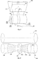
- the first roller 230 comprises a disc-shaped portion 232, a pair of truncated-cone-shaped portions 234 that sandwich the disc-shaped portion 232, and a pair of column-shaped portions 236 arranged outside the respective pair of truncated-cone-shaped portions 234.
- the respective portions of the first roller 230 are integrally arranged such that their rotation centers are positioned along the same axis.
- the pair of truncated-cone-shaped portions 234 are symmetrically arranged with respect to the disc-shaped portion 232 with the smaller-diameter faces 234a facing inside and the larger-diameter faces 234b facing outside.
- the diameter of the disc-shaped portion 232 is larger than the diameter of the larger-diameter face 234a of the truncated-cone-shaped portion 234.
- the second roller 240 is a column-shaped portion as a whole, where the rotation center axis lines of the first and second rollers 230 and 240 are arranged to be parallel to each other.
- the first roller 230 and the second roller 240 in Figures 3 and 4 may be arranged reversely.
- the entire surface of the truncated-cone-shaped portion 234 is provided with a dot pattern 234c, by which a light-reflecting surface is formed on the non-uniform-thickness portion 124.
- the second roller 240 has a smooth surface.
- the manufacturing apparatus 200 heats a resin as a material of a light guide film to a temperature that allows the resin to have a low viscosity with a heating means (not shown).
- This resin is divided into two by the inner deckel 205 inside the manifold section 203 of the die 201, and extruded as two resin plates 110 from the extrusion port 202 of the die 201.
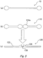
- Figure 5(a) shows a cross-sectional shape of a resin plate 10 of a comparative example without the inner deckel 205.
- FIG. 5(b) is a cross section of the resin plates 110 cut along line A1-A1 shown in Figure 3 .
- the resin plates 110 extruded from the extrusion port 202 have been divided into two by the inner deckel 205, and each of them has thick portions (uneven portions) 114a at both ends.
- Figure 5(c) is a cross section of the molded body 120 cut along line B1-B1 shown in Figure 3 .
- the preliminary-molded resin plates 110 shown in Figure 5(b) are guided to the two-stage rollers (main molding section) including the first and second rollers 230 and 240.
- the first and second rollers 230 and 240 shape the resin plates 110 to make a molded body 120. Specifically, as the resin plates 110 pass through the first and second rollers 230 and 240, the two thick portions 114a formed by the inner deckel 205 are guided to the disc-shaped portion 232 and the column-shaped portion 236 of the first roller 230.
- the connecting portion 128 is formed from parts of the thick portions 114a of the resin plates 110 between the disc-shaped portion 232 of the first roller 230 and the second roller 240, the non-uniform-thickness portion 124 is formed from the thick portions 114a of the resin plates 110 between the truncated-cone-shaped portion 234 of the first roller 230 and the second roller 240, and the flat portion 122 is formed between the column-shaped portion 236 of the first roller 230 and the second roller 240.
- the dot pattern 234c of the truncated-cone-shaped portion 234 forms a dot pattern for light reflection on the resin plate.
- a third roller may be added to provide triple rollers.
- the third roller is controlled to have a temperature that is lower than the glass-transition temperature of the resin that forms the molded body 120. Accordingly, at least the surface of the molded body 120 is solidified when the molded body 120 leaves the triple rollers.
- the molded body 120 that left the triple rollers continues to advance while being further cooled in the air, is divided in the longitudinal direction at a cutter section (not shown) with a slitter, an edge knife or the like, and is further divided and cut in the plate width direction with a push-cutter or the like, thereby forming a light guide film.
- dots can be formed simultaneously with the molding of the plastic panel (molded body 120).
- dividing in the longitudinal direction may be omitted, in which case the molded body may be split to make light guide films at the stage of assembling the light guide film into a product.
- the disc-shaped portion 232 shown in Figure 4 may be omitted. In this case, the thick center part of the molded body 120 of the non-uniform-thickness film can be cut to make light guide films.
- first and second rollers 330 and 340 shown in Figure 8 are used instead of the first and second rollers 230 and 240 of the first embodiment.
- Figure 6 is a cross-sectional view of a molded body of a non-uniform-thickness film extruded by the manufacturing apparatus and method of the second embodiment, shown in a direction vertical to the extruding direction.
- the molded body 220 consists of two molded sub-bodies 220'.
- the molded sub-body 220' is provided with a flat portion 222 that has a uniform film thickness, a non-uniform-thickness portion 224 whose film thickness changes, and a connecting portion 228 whose film thickness is thinner than the flat portion 222.
- the top surface of the molded body 220' is formed to rise on the non-uniform-thickness portion 224 side while the bottom surface of the molded body 220' is formed to be flat.
- the thickness (film thickness) of the non-uniform-thickness portion 224 decreases from the first side part 226 on the connecting portion 228 side towards the second side part 230 on the flat portion 232 side.
- the side parts 226 of the two non-uniform-thickness portions 224 oppose to each other via the connecting portion 228.
- the connecting portion 228 is formed on the top surface side of the rising molded body 120'.
- Figure 7 is a perspective view showing the molded sub-body 220' obtained by cutting the molded body 220 of the non-uniform-thickness film shown in Figure 6 .
- the molded sub-bodies 220' are cut along a cut plane 228a of the connecting portion 228 that is parallel to the extruding direction, and also cut along two cut planes 232 that are vertical to the extruding direction.
- the two molded sub-bodies 220' are integrally molded to be symmetrically arranged side by side such that both side parts 226 thereof oppose to each other as shown in Figure 6 .
- multiple molded bodies including these two molded sub-bodies 220' may integrally be molded to be arranged side by side by connecting the side parts 230 via connecting portions. The entire connecting portion 228 is cut off from the molded sub-body 220' to use the resultant as a light guide film.
- the side part 226 serves as a light incident surface
- the side part 230 serves as an end face
- the sloped surface 224a of the non-uniform-thickness portion 224 serves as a light-reflecting surface
- the upper planar surface of the flat portion 232 serves as a light emitting surface 232a.
- the sloped surface 224a as the light-reflecting surface is formed with a dot pattern.
- a manufacturing apparatus for molding a molded body of a non-uniform-thickness film is similar to the manufacturing apparatus 200 of the first embodiment ( Figure 3 ). Only the first roller and the second roller of the manufacturing apparatus of the second embodiment have structures different from those of the manufacturing apparatus 200. Hereinafter, the first roller 330 and the second roller 340 used in the manufacturing apparatus of the second embodiment will be described.
- the first roller 330 consists of a disc-shaped portion 332, and a pair of column-shaped portions 334 that sandwich the disc-shaped portion 332.
- the respective portions of the first roller 330 are integrally arranged such that their rotation centers are positioned along the same axis.
- the diameter of the disc-shaped portion 332 is larger than the diameter of the column-shaped portion 334.
- the second roller 340 consists of a small-diameter portion 342, a pair of truncated-cone-shaped portions 344 sandwiching the small-diameter portion 342, and a pair of column-shaped portions 346 arranged outside the pair of truncated-cone-shaped portions 344, respectively.
- the pair of truncated-cone-shaped portions 334 are symmetrically arranged to sandwich the small-diameter portion 342 with the smaller-diameter faces 334a facing inside and the larger-diameter faces 334b facing outside.
- the diameter of the smaller-diameter face 344a of the truncated-cone-shaped portion 344 is the same as the diameter of the small-diameter portion 342.
- the small-diameter portion 342 is smoothly connected with the truncated-cone-shaped portion 344 on the smaller-diameter face 344a side.
- the diameter of the larger-diameter face 344b of the truncated-cone-shaped portion 344 is the same as the diameter of the column-shaped portion 346.
- the first roller 330 and the second roller 340 may be arranged reversely. Although it is not shown, the entire surface of the truncated-cone-shaped portion 334 is provided with a dot pattern.
- the first roller 330 has a smooth surface.
- Steps for molding a molded body of a non-uniform-thickness film according to the second embodiment will be described. Steps that are the same as the molding steps of the first embodiment will be omitted.
- the preliminary-molded resin plates 110 extruded from the extrusion port 202 of the die 201 are guided to the two-stage rollers (main molding section) including the first and second rollers 330 and 340.
- a connecting portion 228 is formed from the thick portions 114a of the resin plate 110 between the disc-shaped portion 332 of the first roller 340 and the small-diameter portion 342 of the second roller 340
- a non-uniform-thickness portion 224 is formed from the thick portions 114a of the resin plate 110 between the inner part of the column-shaped portion 334 of the first roller 330 and the truncated-cone-shaped portion 344 of the second roller 340
- a flat portion 222 is formed between the outer part of the column-shaped portion 334 of the first roller 330 and the column-shaped portion 346 of the second roller 340.
- the dot pattern of the truncated-cone-shaped portion 344 forms a dot pattern for light reflection on the resin plate.
- the disc-shaped portion 332 shown in Figure 7 may be omitted.
- the thick center part of the molded body 120 of the non-uniform-thickness film can be cut to make light guide films.
- a tandem machine comprising a first die 201 A and a second die 201B is used to mold and provide a thick portion to a resin plate.
- the first die 201A and the second die 201B composing a preliminary molding section is arranged above and parallel to the first roller 230 (330) and the second roller 240 (340).
- the first die 201A has the same structure as the die 201 shown in Figure 3 except that the first die 201A differs from the die 201 in that it is not provided with a center deckel 205. Accordingly, a wide resin plate 110A is extruded from the extrusion port 202A of the die 201 A.
- the second die 201B also has a similar structure to the die 201 shown in Figure 3 except that the second die 201 B is not provided with a center deckel 205 but provided with a pair of inner deckels 205B inside a manifold section 203B.
- the pair of inner deckels 205B are brought inwardly and arranged such that the resin flow path within the manifold section 203B is narrowed. This arrangement allows a width of a resin plate 110B extruded from the extrusion port 202B to be narrower than a width of a resin plate 110A.
- the manufacturing apparatus 200B heats a resin as a material of a light guide film to a temperature that allows the resin to have a low viscosity with a heating means (not shown).
- This resin is extruded as a wide resin plate 110A from the extrusion port 202A of the first die 201A and also as a narrow resin plate 110B from the extrusion port 202B of the second die 201B.
- These resin plates 110A and 110B travel downward while approaching each other and are integrated to form a joined resin plate 115, which is guided and molded between the first roller 230 and the second roller 240.
- Figure 10 (a) is a cross section of the joined resin plate 115 cut along line A2-A2 shown in Figure 9.
- Figure 10 (b) is a cross section of the molded body 120 cut along line B2-B2 shown in Figure 9 .
- the joined resin plate 115 comprises a flat portion 115a that has a thickness corresponding to that of the resin plate 110A and a thick portion (uneven portion) 115b that has a thickness corresponding to those of the resin plate 110A and the resin plate 110B.
- a main molding section comprising the first and second rollers 230 (330) and 240 (340) shown in Figure 4 shapes the joined resin plate 115 to make a molded body 120 (220). Specifically, as the thick portion 115b of the joined resin plate 115 passes through the first and second rollers 230 and 240, it is guided between the disc-shaped portion 232 of the first roller 230 and the column-shaped second roller 240.
- the connecting portion 128 is formed from a part of the thick portion 115b of the joined resin plate 115 between the disc-shaped portion 232 of the first roller 230 and the second roller 240, the non-uniform-thickness portion 124 is formed from the thick portion 115b of the joined resin plate 115 between the truncated-cone-shaped portion 234 of the first roller 230 and the second roller 240, and the flat portion 122 is formed from the flat portion 115a of the joined resin plate 115 between the column-shaped portion 236 of the first roller 230 and the second roller 240.
- FIG. 11 (a) shows a manufacturing apparatus 20 of a comparative example, which is a conventional film manufacturing apparatus that is not used for manufacturing a non-uniform-thickness film.
- a die 21 of the manufacturing apparatus 20 is provided with a lip section 29 with a rectangular-shaped opening as an extrusion port, and extrudes a resin plate 10 with a flat rectangular-shaped cross section.
- a lip section 209 of a die 201C of the manufacturing apparatus 200C of the fourth embodiment is provided with notched portions 209C (a preliminary molding section) as shown in Figure 11(b) .
- the notched portions 209C are shown to have rectangular shapes, they are not limited thereto, and the notched portions 209C may be formed to have polygonal (triangular, rectangular or trapezoidal), semicircular or semi-elliptic shapes or the like.
- the number, the size and the arrangement of the notched portions 209C may suitably be altered according to the position and/or the shape of the thick portion of the molded body 120.
- the manufacturing apparatus 200C heats a resin as a material of a light guide film to a temperature that allows the resin to have a low viscosity with a heating means (not shown).
- This resin is extruded as an uneven resin plate 110C from the lip section 209 provided at the extrusion port of the die 201C.
- the uneven resin plate 110C is guided to and fully molded between the first roller 230 (330) and the second roller 240 (340) to form a molded body 120.
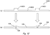
- Figure 12(a) is a cross section of the uneven resin plate 110C cut along line A3-A3 shown in Figure 11 .
- Figure 12(b) is a cross section of the molded body 120 cut along line B3-B3 shown in Figure 11 .
- the uneven resin plate 110C comprises thick portions (uneven portions) 110C1 corresponding to the notched portions 209C and a flat portion 110C2.
- a main molding section comprising the first and second rollers 230 and 240 shown in Figure 4 shapes the uneven resin plate 110C to make a molded body 120. Specifically, as the thick portions 110C1 of the uneven resin plate 110C pass through the first and second rollers 230 and 240, they are guided to the disc-shaped portion 232 and the column-shaped portion 236 of the first roller 230.
- the connecting portion 128 is formed from parts of the thick portions 110C1 of the uneven resin plate 110C between the disc-shaped portion 232 of the first roller 230 and the second roller 240, the non-uniform-thickness portions 124 are formed from the thick portions 115b of the uneven resin plate 110C between the truncated-cone-shaped portions 234 of the first roller 230 and the second roller 240, and the flat portion 122 is formed from the flat portion 110C2 of the uneven resin plate 110C between the column-shaped portion 236 of the first roller 230 and the second roller 240.
- rollers are not limited to two, and may be three, i.e., the first, second and third rollers, or four or more.
- a transparent resin such as an acrylic resin, a polycarbonate resin or the like is used as a non-uniform-thickness film that is used for manufacturing a light guide film.
- a polarizing element may be embossed onto the bottom surface of the molded body 120 or 220 using an indented embossing surface.
- the first and second rollers 230 and 240 are interchangeable with the first and second rollers 330 and 340.
- the present invention is capable of continuously and inexpensively manufacturing a non-uniform-thickness film as a molded body having a shape with an uneven-cross-section as typified by a wedge-shaped light guide film.
Landscapes
- Engineering & Computer Science (AREA)
- Mechanical Engineering (AREA)
- Manufacturing & Machinery (AREA)
- Physics & Mathematics (AREA)
- Thermal Sciences (AREA)
- General Engineering & Computer Science (AREA)
- Health & Medical Sciences (AREA)
- Ophthalmology & Optometry (AREA)
- Electromagnetism (AREA)
- Extrusion Moulding Of Plastics Or The Like (AREA)
- Shaping Of Tube Ends By Bending Or Straightening (AREA)
- Liquid Crystal (AREA)
- Casting Or Compression Moulding Of Plastics Or The Like (AREA)
Abstract
Description
- The present invention relates to an apparatus and a method for manufacturing a non-uniform-thickness film made of a synthetic resin, for example, a non-uniform-thickness film that is used as a light guide plate incorporated in a backlighting device of a liquid crystal display device.
- A liquid crystal display device such as a tablet PC, a smartphone or the like employs a light guide plate (light guide film) of a edge-lit type as a back lighting device. An edge-lit-type light guide plate emits light incident on one edge (light incident surface) of the transparent square plate from its surface (light emitting surface). A back lighting device has a light source arranged on at least one edge of the light guide plate. The surface opposing the light emitting surface of the light guide plate (light-reflecting surface) is provided with an element for changing the advancing angle of the light transmitting inside the light guide plate (hereinafter, referred to as a "polarizing element"). Light incident on the light incident surface of the light guide plate is reflected by the light-reflecting surface, by which the advancing direction of the light is changed and the light propagates within the light guide plate and is emitted from the light emitting surface. In general, the light guide plate is provided with a polarizing element whose density distribution and shape are determined such that the brightness of the light is uniform over the entire light emitting surface.
- A method for manufacturing such a light guide plate is generally an injection molding method like the method disclosed in Japanese Unexamined Patent Application Publication No.
Heisei 9-222514 - As a method for solving such problems, a method for manufacturing a non-uniform-thickness film with an extruder has been proposed, in which at least two non-uniform-thickness films are extruded to be integrally molded such that they are symmetrically arranged side by side, like the method disclosed in Japanese Unexamined Patent Application Publication No.
2004-82359 -
- Patent Document 1: Japanese Unexamined Patent Application Publication No.
Heisei 9-222514 - Patent Document 2: Japanese Unexamined Patent Application Publication No.
2004-82359 - However, in order to obtain a light guide film by the manufacturing method disclosed in Japanese Unexamined Patent Application Publication No.
2004-82359 - The present invention was made considering the above-described circumstances. The present invention has an objective of providing an apparatus for manufacturing a non-uniform-thickness film, which is capable of efficiently manufacturing the non-uniform-thickness film. In addition, the present invention has an objective of providing an apparatus and a method for manufacturing a non-uniform-thickness film, wherein a light guide film can easily be made only by dividing (cutting) the manufactured non-uniform-thickness film in a direction substantially vertical to the extruding direction.
- In order to solve the above-described problem, the present invention is constituted as follows.
- (Aspect 1) An apparatus for manufacturing a non-uniform-thickness film comprising a die for extruding a resin plate, and a first roller and a second roller for molding the resin plate, wherein the apparatus comprises a preliminary molding section provided on the die side in order to mold an uneven portion to the resin plate, the uneven portion being uneven in thickness, and a main molding section provided on the first roller and/or the second roller in order to mold a non-uniform-thickness portion from the uneven portion.
- (Aspect 2) The manufacturing apparatus according to
Aspect 1, wherein the preliminary molding section divides and extrudes the resin plate in the die. (Aspect 3) The manufacturing apparatus according to Aspect 2, wherein the preliminary molding section is provided with one or more deckels on the die side. (Aspect 4) The manufacturing apparatus according toAspect 1, wherein the preliminary molding section comprises the die and a second die for extruding a second resin plate whose width differs from that of the resin plate. (Aspect 5) The manufacturing apparatus according to Aspect 4, wherein the die and the second die are arranged side by side such that the resin plate extruded from the die and the second resin plate extruded from the second die join to form a resin plate having the uneven portion. - (Aspect 6) The manufacturing apparatus according to either one of Aspects 4 and 5, wherein the preliminary molding section comprises an inner deckel in the second die in order to narrow a resin flow path in the second die. (Aspect 7) The manufacturing apparatus according to
Aspect 1, wherein the preliminary molding section has one or more notched portions provided at a lip section of an extrusion port of the die. (Aspect 8) The manufacturing apparatus according to Aspect 7, wherein the notched portion is semicircular, semi-elliptic, dorm-shaped or polygonal. (Aspect 9) The manufacturing apparatus according to Aspect 8, wherein the polygonal shape is a triangle, a rectangle or a trapezoid. (Aspect 10) The manufacturing apparatus according to any one of Aspects 1-9, wherein the main molding section comprises a truncated-cone-shaped portion provided on the first roller and a column-shaped portion provided on the second roller. (Aspect 11) The manufacturing apparatus according to any one of Aspects 1-9, wherein the main molding section comprises a truncated-cone-shaped portion and a disc-shaped portion provided on the first roller, and a column-shaped portion provided on the second roller, where the diameter of the disc-shaped portion is larger than the diameter of the larger-diameter face of the truncated-cone-shaped portion. - (Aspect 12) The manufacturing apparatus according to Aspect 11, wherein the manufacturing apparatus forms and provides a thick portion to a molded body of the non-uniform-thickness film between the truncated-cone-shaped portion of the first roller and the column-shaped portion of the second roller, and forms and provides a thin connecting portion to the molded body between the disc-shaped portion of the first roller and the column-shaped portion of the second roller. (Aspect 13) The manufacturing apparatus according to either one of Aspects 11 and 12, wherein the truncated-cone-shaped portion is a pair of truncated-cone-shaped portions, which are symmetrically arranged to sandwich the disc-shaped portion. (Aspect 14) The manufacturing apparatus according to any one of Aspects 10-13, wherein the respective portions configuring the first roller are integrally arranged on the same axis. (Aspect 15) The manufacturing apparatus according to any one of Aspects 10-14, wherein the disc-shaped portion is connected with the smaller-diameter face of the truncated-cone-shaped portion.
- (Aspect 16) The manufacturing apparatus according to any one of Aspects 10-15, wherein the first roller further comprises a column-shaped portion. (Aspect 17) The manufacturing apparatus according to Aspect 16, wherein the column-shaped portion of the first roller is connected with the larger-diameter face of the truncated-cone-shaped portion of the first roller. (Aspect 18) The manufacturing apparatus according to any one of Aspects 1-9, wherein the main molding section comprises: a column-shaped portion and a disc-shaped portion provided on the first roller; and a truncated-cone-shaped portion and a small-diameter portion provided on the second roller, wherein the small-diameter portion is smoothly connected with the smaller-diameter face of the truncated-cone-shaped portion. (Aspect 19) The manufacturing apparatus according to Aspect 18, wherein the manufacturing apparatus forms a non-uniform-thickness portion to a molded body of the non-uniform-thickness film between the column-shaped portion of the first roller and the truncated-cone-shaped portion of the second roller, and forms a thin connecting portion to the molded body between the disc-shaped portion of the first roller and the small-diameter portion of the second roller.
- (Aspect 20) The manufacturing apparatus according to either one of Aspects 18 and 19, wherein the truncated-cone-shaped portion is a pair of truncated-cone-shaped portions, which are symmetrically arranged to sandwich the small-diameter portion. (Aspect 21) The manufacturing apparatus according to any one of Aspects 18-20, wherein the respective portions configuring the first roller or the second roller are integrally arranged on the same axis. (Aspect 22) The manufacturing apparatus according to any one of Aspects 9-12, wherein the small-diameter portion is connected with the smaller-diameter face of the truncated-cone-shaped portion. (Aspect 23) The manufacturing apparatus according to any one of Aspects 18-22, wherein the second roller further comprises a column-shaped portion. (Aspect 24) The manufacturing apparatus according to Aspect 23, wherein the column-shaped portion of the second roller is connected with the larger-diameter face of the truncated-cone-shaped portion of the second roller.
- (Aspect 25) The manufacturing apparatus according to either one of Aspects 12 and 19, wherein the non-uniform-thickness portion of the molded body is formed such that the thickness thereof changes from one side part to the other side part that are parallel to the extruding direction. (Aspect 26) The manufacturing apparatus according to any one of Aspects 10-25, wherein the surface of the truncated-cone-shaped portion is provided with a dot pattern. (Aspect 27) The manufacturing apparatus according to any one of Aspects 10-26, comprising a cutter section for cutting the molded body molded with the first roller and the second roller. (Aspect 28) The manufacturing apparatus according to any one of Aspects 12, 19 and 25, wherein the molded body of the non-uniform-thickness film comprises multiple molded sub-bodies, which are connected via the connecting portion.
- (Aspect 29) A method for manufacturing a non-uniform-thickness film where the non-uniform-thickness film is molded using a die for extruding a resin plate and a first roller and a second roller for molding the resin plate, the method comprising: preliminarily molding an uneven portion being uneven in thickness to the resin plate by using a preliminary molding section provided on the die side; and mainly molding a non-uniform-thickness portion from the uneven portion by using a main molding section provided on the first roller and/or the second roller.
- According to the present invention, a resin plate that is preliminarily molded by a preliminary molding section can further be molded by a main molding section so that a non-uniform-thickness film that can easily be divided can be manufactured continuously.
-
- [
Figure 1 ] A cross-sectional view of a non-uniform-thickness film manufactured in a first embodiment of the present invention. - [
Figure 2 ] A perspective view showing a molded sub-body of the non-uniform-thickness film shown inFigure 1 . - [
Figure 3 ] A perspective view showing a manufacturing apparatus according to the first embodiment of the present invention. - [
Figure 4 ] A top perspective view showing first and second rollers of the manufacturing apparatus shown inFigure 3 . - [
Figure 5 ] A schematic view showing a molding process using the manufacturing apparatus ofFigure 3 . - [
Figure 6 ] A cross-sectional view of a non-uniform-thickness film manufactured in a second embodiment of the present invention. - [
Figure 7 ] A perspective view showing a molded sub-body of the non-uniform-thickness film shown inFigure 6 . - [
Figure 8 ] A top perspective view showing first and second rollers of the manufacturing apparatus according to the second embodiment of the present invention. - [
Figure 9 ] A perspective view showing a manufacturing apparatus according to a third embodiment of the present invention. - [
Figure 10 ] A schematic view showing a molding process using the manufacturing apparatus ofFigure 9 . - [
Figure 11 ] (a) A perspective view showing a manufacturing apparatus according to a comparative example and (b) a perspective view showing a manufacturing apparatus according to a fourth embodiment of the present invention. - [
Figure 12 ] A schematic view showing a molding process using the manufacturing apparatus ofFigure 11(b) . - Embodiments of an apparatus and a method for manufacturing a non-uniform-thickness film of the present invention will be described with reference to the drawings. In each figure, like parts are denoted by like reference numerals and the description thereof is omitted.
- A manufacturing apparatus and method according to a first embodiment of the present invention will be described with reference to
Figures 1-5 . In the first embodiment, a resin plate is extruded while dividing the resin with a deckel provided in a die so that thick portions are preliminarily molded at the ends of the divided resin plate and then a non-uniform-thickness portion is fully molded and provided to the resin plate with first and the second rollers. -
Figure 1 is a cross-sectional view of a molded body of a non-uniform-thickness film extruded by the manufacturing apparatus and method of the first embodiment, shown in a direction vertical to the extruding (longitudinal) direction. The moldedbody 120 consists of two molded sub-bodies 120'. The molded sub-body 120' is provided with aflat portion 122 that has a uniform film thickness, a non-uniform-thickness portion 124 whose film thickness changes, and a connectingportion 128 whose film thickness is thinner than theflat portion 122. The top surface of the molded body 120' is formed to rise on the non-uniform-thickness portion 124 side while the bottom surface of the molded body 120' is formed to be flat. The thickness (film thickness) of the non-uniform-thickness portion 124 decreases from thefirst side part 126 on the connectingportion 128 side towards thesecond side part 130 on theflat portion 122 side. Theside parts 126 of the two non-uniform-thickness portions 124 oppose to each other via the connectingportion 128. The connectingportion 128 is formed on the bottom surface side of the molded bodies 120'. -
Figure 2 is a perspective view showing a molded sub-body 120' obtained by cutting the moldedbody 120 of the non-uniform-thickness film shown inFigure 1 . The molded sub-body 120' is cut along the cut plane 128a of the connectingportion 128 parallel to the extruding direction, and also cut along two cutplanes 132 that are vertical to the extruding direction. - According to the first embodiment, the two molded sub-bodies 120' are integrally molded to be symmetrically arranged side by side such that the
side parts 126 thereof oppose to each other as shown inFigure 1 . Alternatively, multiple molded bodies including these two molded sub-bodies 120' may integrally be molded to be arranged side by side by connecting theside parts 130 via connecting portions. The entire connectingportion 128 is cut off from the molded sub-body 120' to use the resultant as a light guide film. - Referring to
Figure 2 , theside part 126 serves as a light incident surface, theside part 130 serves as an end face, the slopedsurface 124a of the non-uniform-thickness portion 124 serves as a light-reflecting surface, and the upper planar surface of theflat portion 122 serves as a light emitting surface. The slopedsurface 124a as the light-reflecting surface is formed with a dot pattern that reflects light as will be described later. -
Figure 3 is a part perspective view of amanufacturing apparatus 200 for molding the molded body of the non-uniform-thickness film shown inFigure 1 . Themanufacturing apparatus 200 is provided with adie 201 for accommodating and extruding a resin, a rectangular-shapedextrusion port 202 formed in thedie 201, afirst roller 230 and asecond roller 240. The first andsecond rollers extrusion port 202 to sandwich apre-molded resin plate 110 extruded from theextrusion port 202. - The
die 201 is provided with amanifold section 203 inside which a resin flows, and aninner deckel 205 arranged within themanifold section 203 and ahead of the extrusion port 202 (a preliminary molding section). A resin that flows inside themanifold section 203 is divided into two streams by theinner deckel 205 and extruded from theextrusion port 202. Alternatively, an outer deckel may be provided at the extrusion port, instead of theinner deckel 205. InFigure 3 , oneinner deckel 205 is provided but the number thereof is not limited thereto and multiple inner deckels may be provided inside themanifold section 203. - With reference to
Figure 4 , the structure of the main molding section comprising thefirst roller 230 and thesecond roller 240 will be described. Thefirst roller 230 comprises a disc-shapedportion 232, a pair of truncated-cone-shapedportions 234 that sandwich the disc-shapedportion 232, and a pair of column-shapedportions 236 arranged outside the respective pair of truncated-cone-shapedportions 234. The respective portions of thefirst roller 230 are integrally arranged such that their rotation centers are positioned along the same axis. The pair of truncated-cone-shapedportions 234 are symmetrically arranged with respect to the disc-shapedportion 232 with the smaller-diameter faces 234a facing inside and the larger-diameter faces 234b facing outside. The diameter of the disc-shapedportion 232 is larger than the diameter of the larger-diameter face 234a of the truncated-cone-shapedportion 234. Thesecond roller 240 is a column-shaped portion as a whole, where the rotation center axis lines of the first andsecond rollers first roller 230 and thesecond roller 240 inFigures 3 and 4 may be arranged reversely. As shown inFigure 4 , the entire surface of the truncated-cone-shapedportion 234 is provided with adot pattern 234c, by which a light-reflecting surface is formed on the non-uniform-thickness portion 124. Thesecond roller 240 has a smooth surface. - Steps for molding a molded body of a non-uniform-thickness film with the
manufacturing apparatus 200 will be described. Themanufacturing apparatus 200 heats a resin as a material of a light guide film to a temperature that allows the resin to have a low viscosity with a heating means (not shown). This resin is divided into two by theinner deckel 205 inside themanifold section 203 of thedie 201, and extruded as tworesin plates 110 from theextrusion port 202 of thedie 201.Figure 5(a) shows a cross-sectional shape of aresin plate 10 of a comparative example without theinner deckel 205. Theresin plate 10 has ball-shaped thick portions at both endsFigure 5(b) is a cross section of theresin plates 110 cut along line A1-A1 shown inFigure 3 . As shown inFigure 5(b) , theresin plates 110 extruded from theextrusion port 202 have been divided into two by theinner deckel 205, and each of them has thick portions (uneven portions) 114a at both ends.Figure 5(c) is a cross section of the moldedbody 120 cut along line B1-B1 shown inFigure 3 . - The preliminary-molded
resin plates 110 shown inFigure 5(b) are guided to the two-stage rollers (main molding section) including the first andsecond rollers second rollers resin plates 110 to make a moldedbody 120. Specifically, as theresin plates 110 pass through the first andsecond rollers thick portions 114a formed by theinner deckel 205 are guided to the disc-shapedportion 232 and the column-shapedportion 236 of thefirst roller 230. Then, the connectingportion 128 is formed from parts of thethick portions 114a of theresin plates 110 between the disc-shapedportion 232 of thefirst roller 230 and thesecond roller 240, the non-uniform-thickness portion 124 is formed from thethick portions 114a of theresin plates 110 between the truncated-cone-shapedportion 234 of thefirst roller 230 and thesecond roller 240, and theflat portion 122 is formed between the column-shapedportion 236 of thefirst roller 230 and thesecond roller 240. Thedot pattern 234c of the truncated-cone-shapedportion 234 forms a dot pattern for light reflection on the resin plate. - Although it is not shown in
Figure 3 , a third roller may be added to provide triple rollers. Usually, the third roller is controlled to have a temperature that is lower than the glass-transition temperature of the resin that forms the moldedbody 120. Accordingly, at least the surface of the moldedbody 120 is solidified when the moldedbody 120 leaves the triple rollers. The moldedbody 120 that left the triple rollers continues to advance while being further cooled in the air, is divided in the longitudinal direction at a cutter section (not shown) with a slitter, an edge knife or the like, and is further divided and cut in the plate width direction with a push-cutter or the like, thereby forming a light guide film. Thus dots can be formed simultaneously with the molding of the plastic panel (molded body 120). Depending on the thickness or the width of the connectingportion 128 of the thin film shown inFigure 1 , dividing in the longitudinal direction may be omitted, in which case the molded body may be split to make light guide films at the stage of assembling the light guide film into a product. Furthermore, in the first embodiment, the disc-shapedportion 232 shown inFigure 4 may be omitted. In this case, the thick center part of the moldedbody 120 of the non-uniform-thickness film can be cut to make light guide films. - A manufacturing apparatus and method of a second embodiment of the present invention will be described with reference to
Figures 6-8 . In the second embodiment, first andsecond rollers Figure 8 are used instead of the first andsecond rollers -
Figure 6 is a cross-sectional view of a molded body of a non-uniform-thickness film extruded by the manufacturing apparatus and method of the second embodiment, shown in a direction vertical to the extruding direction. The moldedbody 220 consists of two molded sub-bodies 220'. The molded sub-body 220' is provided with aflat portion 222 that has a uniform film thickness, a non-uniform-thickness portion 224 whose film thickness changes, and a connectingportion 228 whose film thickness is thinner than theflat portion 222. The top surface of the molded body 220' is formed to rise on the non-uniform-thickness portion 224 side while the bottom surface of the molded body 220' is formed to be flat. The thickness (film thickness) of the non-uniform-thickness portion 224 decreases from thefirst side part 226 on the connectingportion 228 side towards thesecond side part 230 on theflat portion 232 side. Theside parts 226 of the two non-uniform-thickness portions 224 oppose to each other via the connectingportion 228. The connectingportion 228 is formed on the top surface side of the rising molded body 120'. -
Figure 7 is a perspective view showing the molded sub-body 220' obtained by cutting the moldedbody 220 of the non-uniform-thickness film shown inFigure 6 . The molded sub-bodies 220' are cut along acut plane 228a of the connectingportion 228 that is parallel to the extruding direction, and also cut along two cutplanes 232 that are vertical to the extruding direction. - According to the second embodiment, the two molded sub-bodies 220' are integrally molded to be symmetrically arranged side by side such that both
side parts 226 thereof oppose to each other as shown inFigure 6 . Alternatively, multiple molded bodies including these two molded sub-bodies 220' may integrally be molded to be arranged side by side by connecting theside parts 230 via connecting portions. The entire connectingportion 228 is cut off from the molded sub-body 220' to use the resultant as a light guide film. - Referring to
Figure 7 , theside part 226 serves as a light incident surface, theside part 230 serves as an end face, the slopedsurface 224a of the non-uniform-thickness portion 224 serves as a light-reflecting surface, and the upper planar surface of theflat portion 232 serves as a light emitting surface 232a. The slopedsurface 224a as the light-reflecting surface is formed with a dot pattern. - In the second embodiment, a manufacturing apparatus for molding a molded body of a non-uniform-thickness film is similar to the
manufacturing apparatus 200 of the first embodiment (Figure 3 ). Only the first roller and the second roller of the manufacturing apparatus of the second embodiment have structures different from those of themanufacturing apparatus 200. Hereinafter, thefirst roller 330 and thesecond roller 340 used in the manufacturing apparatus of the second embodiment will be described. - As shown in
Figure 8 , thefirst roller 330 consists of a disc-shapedportion 332, and a pair of column-shapedportions 334 that sandwich the disc-shapedportion 332. The respective portions of thefirst roller 330 are integrally arranged such that their rotation centers are positioned along the same axis. The diameter of the disc-shapedportion 332 is larger than the diameter of the column-shapedportion 334. Thesecond roller 340 consists of a small-diameter portion 342, a pair of truncated-cone-shapedportions 344 sandwiching the small-diameter portion 342, and a pair of column-shapedportions 346 arranged outside the pair of truncated-cone-shapedportions 344, respectively. The pair of truncated-cone-shapedportions 334 are symmetrically arranged to sandwich the small-diameter portion 342 with the smaller-diameter faces 334a facing inside and the larger-diameter faces 334b facing outside. The diameter of the smaller-diameter face 344a of the truncated-cone-shapedportion 344 is the same as the diameter of the small-diameter portion 342. The small-diameter portion 342 is smoothly connected with the truncated-cone-shapedportion 344 on the smaller-diameter face 344a side. The diameter of the larger-diameter face 344b of the truncated-cone-shapedportion 344 is the same as the diameter of the column-shapedportion 346. Alternatively, thefirst roller 330 and thesecond roller 340 may be arranged reversely. Although it is not shown, the entire surface of the truncated-cone-shapedportion 334 is provided with a dot pattern. Thefirst roller 330 has a smooth surface. - Steps for molding a molded body of a non-uniform-thickness film according to the second embodiment will be described. Steps that are the same as the molding steps of the first embodiment will be omitted. The preliminary-molded
resin plates 110 extruded from theextrusion port 202 of thedie 201 are guided to the two-stage rollers (main molding section) including the first andsecond rollers resin plates 110 pass through the first andsecond rollers portion 228 is formed from thethick portions 114a of theresin plate 110 between the disc-shapedportion 332 of thefirst roller 340 and the small-diameter portion 342 of thesecond roller 340, a non-uniform-thickness portion 224 is formed from thethick portions 114a of theresin plate 110 between the inner part of the column-shapedportion 334 of thefirst roller 330 and the truncated-cone-shapedportion 344 of thesecond roller 340, and aflat portion 222 is formed between the outer part of the column-shapedportion 334 of thefirst roller 330 and the column-shapedportion 346 of thesecond roller 340. The dot pattern of the truncated-cone-shapedportion 344 forms a dot pattern for light reflection on the resin plate. In the second embodiment, the disc-shapedportion 332 shown inFigure 7 may be omitted. In this case, the thick center part of the moldedbody 120 of the non-uniform-thickness film can be cut to make light guide films. - An apparatus and a method for manufacturing a non-uniform-thickness film according to a third embodiment of the present invention will be described with reference to
Figures 9 and 10 . In amanufacturing apparatus 200B of the third embodiment, a tandem machine comprising afirst die 201 A and asecond die 201B is used to mold and provide a thick portion to a resin plate. Thefirst die 201A and thesecond die 201B composing a preliminary molding section is arranged above and parallel to the first roller 230 (330) and the second roller 240 (340). - The
first die 201A has the same structure as thedie 201 shown inFigure 3 except that thefirst die 201A differs from thedie 201 in that it is not provided with acenter deckel 205. Accordingly, awide resin plate 110A is extruded from theextrusion port 202A of thedie 201 A. Thesecond die 201B also has a similar structure to the die 201 shown inFigure 3 except that thesecond die 201 B is not provided with acenter deckel 205 but provided with a pair ofinner deckels 205B inside amanifold section 203B. The pair ofinner deckels 205B are brought inwardly and arranged such that the resin flow path within themanifold section 203B is narrowed. This arrangement allows a width of aresin plate 110B extruded from theextrusion port 202B to be narrower than a width of aresin plate 110A. - Steps for molding a molded body of a non-uniform-thickness film with the
manufacturing apparatus 200B will be described. Themanufacturing apparatus 200B heats a resin as a material of a light guide film to a temperature that allows the resin to have a low viscosity with a heating means (not shown). This resin is extruded as awide resin plate 110A from theextrusion port 202A of thefirst die 201A and also as anarrow resin plate 110B from theextrusion port 202B of thesecond die 201B. Theseresin plates resin plate 115, which is guided and molded between thefirst roller 230 and thesecond roller 240. -
Figure 10 (a) is a cross section of the joinedresin plate 115 cut along line A2-A2 shown inFigure 9. Figure 10 (b) is a cross section of the moldedbody 120 cut along line B2-B2 shown inFigure 9 . As can be appreciated fromFigure 10 (a) , the joinedresin plate 115 comprises aflat portion 115a that has a thickness corresponding to that of theresin plate 110A and a thick portion (uneven portion) 115b that has a thickness corresponding to those of theresin plate 110A and theresin plate 110B. - A main molding section comprising the first and second rollers 230 (330) and 240 (340) shown in
Figure 4 shapes the joinedresin plate 115 to make a molded body 120 (220). Specifically, as thethick portion 115b of the joinedresin plate 115 passes through the first andsecond rollers portion 232 of thefirst roller 230 and the column-shapedsecond roller 240. Then, the connectingportion 128 is formed from a part of thethick portion 115b of the joinedresin plate 115 between the disc-shapedportion 232 of thefirst roller 230 and thesecond roller 240, the non-uniform-thickness portion 124 is formed from thethick portion 115b of the joinedresin plate 115 between the truncated-cone-shapedportion 234 of thefirst roller 230 and thesecond roller 240, and theflat portion 122 is formed from theflat portion 115a of the joinedresin plate 115 between the column-shapedportion 236 of thefirst roller 230 and thesecond roller 240. - An apparatus and a method for manufacturing a non-uniform-thickness film of a fourth embodiment of the present invention will be described with reference to
Figures 11 and12 . Amanufacturing apparatus 200C of the fourth embodiment forms a thick portion by making a lip section of the die to have an uneven shape.Figure 11 (a) shows amanufacturing apparatus 20 of a comparative example, which is a conventional film manufacturing apparatus that is not used for manufacturing a non-uniform-thickness film. A die 21 of themanufacturing apparatus 20 is provided with alip section 29 with a rectangular-shaped opening as an extrusion port, and extrudes aresin plate 10 with a flat rectangular-shaped cross section. - On the other hand, a
lip section 209 of adie 201C of themanufacturing apparatus 200C of the fourth embodiment is provided with notchedportions 209C (a preliminary molding section) as shown inFigure 11(b) . Although the notchedportions 209C are shown to have rectangular shapes, they are not limited thereto, and the notchedportions 209C may be formed to have polygonal (triangular, rectangular or trapezoidal), semicircular or semi-elliptic shapes or the like. Moreover, the number, the size and the arrangement of the notchedportions 209C may suitably be altered according to the position and/or the shape of the thick portion of the moldedbody 120. - Steps for molding a molded body of a non-uniform-thickness film with the
manufacturing apparatus 200C will be described. Themanufacturing apparatus 200C heats a resin as a material of a light guide film to a temperature that allows the resin to have a low viscosity with a heating means (not shown). This resin is extruded as anuneven resin plate 110C from thelip section 209 provided at the extrusion port of thedie 201C. Theuneven resin plate 110C is guided to and fully molded between the first roller 230 (330) and the second roller 240 (340) to form a moldedbody 120. -
Figure 12(a) is a cross section of theuneven resin plate 110C cut along line A3-A3 shown inFigure 11 .Figure 12(b) is a cross section of the moldedbody 120 cut along line B3-B3 shown inFigure 11 . As can be appreciated fromFigure 12(a) , theuneven resin plate 110C comprises thick portions (uneven portions) 110C1 corresponding to the notchedportions 209C and a flat portion 110C2. - A main molding section comprising the first and
second rollers Figure 4 shapes theuneven resin plate 110C to make a moldedbody 120. Specifically, as the thick portions 110C1 of theuneven resin plate 110C pass through the first andsecond rollers portion 232 and the column-shapedportion 236 of thefirst roller 230. Then, the connectingportion 128 is formed from parts of the thick portions 110C1 of theuneven resin plate 110C between the disc-shapedportion 232 of thefirst roller 230 and thesecond roller 240, the non-uniform-thickness portions 124 are formed from thethick portions 115b of theuneven resin plate 110C between the truncated-cone-shapedportions 234 of thefirst roller 230 and thesecond roller 240, and theflat portion 122 is formed from the flat portion 110C2 of theuneven resin plate 110C between the column-shapedportion 236 of thefirst roller 230 and thesecond roller 240. - Although each embodiment was described using two-stage rollers, the number of rollers is not limited to two, and may be three, i.e., the first, second and third rollers, or four or more. In each embodiment, a transparent resin such as an acrylic resin, a polycarbonate resin or the like is used as a non-uniform-thickness film that is used for manufacturing a light guide film. In each embodiment, a polarizing element may be embossed onto the bottom surface of the molded
body second rollers second rollers - As can be appreciated from the above description, the present invention is capable of continuously and inexpensively manufacturing a non-uniform-thickness film as a molded body having a shape with an uneven-cross-section as typified by a wedge-shaped light guide film.
-
- 110
- Resin plate
- 110A
- Resin plate
- 110B
- Resin plate
- 110C
- Resin plate
- 115
- Joined resin plate
- 120
- Molded body
- 124
- Non-uniform-thickness portion
- 122
- Flat portion
- 128
- Connecting portion
- 200
- Manufacturing apparatus
- 200B
- Manufacturing apparatus
- 200C
- Manufacturing apparatus
- 201
- Die
- 202
- Extrusion port
- 203
- Manifold section
- 205
- Center deckel
- 205B
- Inner deckel
- 209
- Lip section
- 209C
- Notched portion
- 230
- First roller
- 240
- Second roller
- 232
- Disc-shaped portion
- 234
- Truncated-cone-shaped portion
- 236
- Column-shaped portion
- 220
- Molded body
- 224
- Non-uniform-thickness portion
- 222
- Flat portion
- 228
- Connecting portion
- 330
- First roller
- 340
- Second roller
- 332
- Disc-shaped portion
- 334
- Column-shaped portion
- 342
- Small-diameter portion
- 344
- Truncated-cone-shaped portion
- 346
- Column-shaped portion
Claims (29)
- An apparatus for manufacturing a non-uniform-thickness film comprising a die for extruding a resin plate, and a first roller and a second roller for molding the resin plate, wherein the apparatus comprises:a preliminary molding section provided on the die side in order to mold an uneven portion to the resin plate, the uneven portion being uneven in thickness; anda main molding section provided on the first roller and/or the second roller in order to mold a non-uniform-thickness portion from the uneven portion.
- The manufacturing apparatus according to Claim 1, wherein the preliminary molding section divides and extrudes the resin plate on the die side.
- The manufacturing apparatus according to Claim 2, wherein the preliminary molding section is provided with one or more deckels in the die.
- The manufacturing apparatus according to Claim 1, wherein the preliminary molding section comprises the die and a second die for extruding a second resin plate whose width differs from that of the resin plate.
- The manufacturing apparatus according to Claim 4, wherein the die and the second die are arranged side by side such that the resin plate extruded from the die and the second resin plate extruded from the second die join to form a resin plate having the uneven portion.
- The manufacturing apparatus according to either one of Claims 4 and 5, wherein the preliminary molding section comprises an inner deckel in the second die in order to narrow a resin flow path in the second die.
- The manufacturing apparatus according to Claim 1, wherein the preliminary molding section has one or more notched portions provided at a lip section of an extrusion port of the die.
- The manufacturing apparatus according to Claim 7, wherein the notched portion is semicircular, semi-elliptic, dorm-shaped or polygonal.
- The manufacturing apparatus according to Claim 8, wherein the polygonal shape is a triangle, a rectangle or a trapezoid.
- The manufacturing apparatus according to any one of Claims 1-9, wherein the main molding section comprises a truncated-cone-shaped portion provided on the first roller and a column-shaped portion provided on the second roller.
- The manufacturing apparatus according to any one of Claims 1-9, wherein the main molding section comprises a truncated-cone-shaped portion and a disc-shaped portion provided on the first roller, and a column-shaped portion provided on the second roller, where the diameter of the disc-shaped portion is larger than the diameter of the larger-diameter face of the truncated-cone-shaped portion.
- The manufacturing apparatus according to Claim 11, wherein the manufacturing apparatus forms and provides a thick portion to a molded body of the non-uniform-thickness film between the truncated-cone-shaped portion of the first roller and the column-shaped portion of the second roller, and forms and provides a thin connecting portion to the molded body between the disc-shaped portion of the first roller and the column-shaped portion of the second roller.
- The manufacturing apparatus according to either one of Claims 11 and 12, wherein the truncated-cone-shaped portion is a pair of truncated-cone-shaped portions, which are symmetrically arranged to sandwich the disc-shaped portion.
- The manufacturing apparatus according to any one of Claims 10-13, wherein the respective portions configuring the first roller are integrally arranged on the same axis.
- The manufacturing apparatus according to any one of Claims 11-14, wherein the disc-shaped portion is connected with the smaller-diameter face of the truncated-cone-shaped portion.
- The manufacturing apparatus according to any one of Claims 10-15, wherein the first roller further comprises a column-shaped portion.
- The manufacturing apparatus according to Claim 16, wherein the column-shaped portion of the first roller is connected with the larger-diameter face of the truncated-cone-shaped portion of the first roller.
- The manufacturing apparatus according to any one of Claims 1-9, wherein the main molding section comprises: a column-shaped portion and a disc-shaped portion provided on the first roller; and a truncated-cone-shaped portion and a small-diameter portion provided on the second roller, wherein the small-diameter portion is smoothly connected with the smaller-diameter face of the truncated-cone-shaped portion.
- The manufacturing apparatus according to Claim 18, wherein the manufacturing apparatus forms and provides a non-uniform-thickness portion to a molded body of the non-uniform-thickness film between the column-shaped portion of the first roller and the truncated-cone-shaped portion of the second roller, and forms and provides a thin connecting portion to the molded body between the disc-shaped portion of the first roller and the small-diameter portion of the second roller.
- The manufacturing apparatus according to either one of Claims 18 and 19, wherein the truncated-cone-shaped portion is a pair of truncated-cone-shaped portions, which are symmetrically arranged to sandwich the small-diameter portion.
- The manufacturing apparatus according to any one of Claims 18-20, wherein the respective portions configuring the first roller or the second roller are integrally arranged on the same axis.
- The manufacturing apparatus according to any one of Claims 9-12, wherein the small-diameter portion is connected with the smaller-diameter face of the truncated-cone-shaped portion.
- The manufacturing apparatus according to any one of Claims 18-22, wherein the second roller further comprises a column-shaped portion.
- The manufacturing apparatus according to Claim 23, wherein the column-shaped portion of the second roller is connected with the larger-diameter face of the truncated-cone-shaped portion of the second roller.
- The manufacturing apparatus according to either one of Claims 12 and 19, wherein the non-uniform-thickness portion of the molded body is formed such that the thickness thereof changes from one side part to the other side part that are parallel to the extruding direction.
- The manufacturing apparatus according to any one of Claims 10-25, wherein the surface of the truncated-cone-shaped portion is provided with a dot pattern.
- The manufacturing apparatus according to any one of Claims 10-26, comprising a cutter section for cutting the molded body molded with the first roller and the second roller.
- The manufacturing apparatus according to any one of Claims 12, 19 and 25, wherein the molded body of the non-uniform-thickness film comprises multiple molded sub-bodies, which are connected via the connecting portion.
- A method for manufacturing a non-uniform-thickness film where the non-uniform-thickness film is molded using a die for extruding a resin plate and a first roller and a second roller for molding the resin plate, the method comprising:preliminarily molding an uneven portion being uneven in thickness to the resin plate by using a preliminary molding section provided on the die side; andmainly molding a non-uniform-thickness portion from the uneven portion by using a main molding section provided on the first roller and/or the second roller.
Applications Claiming Priority (2)
| Application Number | Priority Date | Filing Date | Title |
|---|---|---|---|
| JP2014115761 | 2014-06-04 | ||
| PCT/JP2015/058277 WO2015186408A1 (en) | 2014-06-04 | 2015-03-19 | Manufacturing apparatus for film of non-uniform thickness and manufacturing method for film of non-uniform thickness |
Publications (3)
| Publication Number | Publication Date |
|---|---|
| EP3153297A1 true EP3153297A1 (en) | 2017-04-12 |
| EP3153297A4 EP3153297A4 (en) | 2018-02-07 |
| EP3153297B1 EP3153297B1 (en) | 2020-07-01 |
Family
ID=54766489
Family Applications (1)
| Application Number | Title | Priority Date | Filing Date |
|---|---|---|---|
| EP15803272.2A Not-in-force EP3153297B1 (en) | 2014-06-04 | 2015-03-19 | Manufacturing apparatus for film of non-uniform thickness and manufacturing method for film of non-uniform thickness |
Country Status (7)
| Country | Link |
|---|---|
| US (1) | US10035289B2 (en) |
| EP (1) | EP3153297B1 (en) |
| JP (1) | JP6465879B2 (en) |
| KR (1) | KR20170013297A (en) |
| CN (1) | CN106414024B (en) |
| TW (1) | TWI674187B (en) |
| WO (1) | WO2015186408A1 (en) |
Families Citing this family (1)
| Publication number | Priority date | Publication date | Assignee | Title |
|---|---|---|---|---|
| EP3831568A1 (en) * | 2019-12-04 | 2021-06-09 | The Swatch Group Research and Development Ltd | Method for marking a decorative item |
Family Cites Families (28)
| Publication number | Priority date | Publication date | Assignee | Title |
|---|---|---|---|---|
| US2382177A (en) * | 1941-10-15 | 1945-08-14 | Goodrich Co B F | Apparatus for making composite strips |
| US3738790A (en) * | 1970-11-03 | 1973-06-12 | G Violette | Apparatus for extruding a film of thermoplastic material having predetermined zones of different film thickness |
| US4057385A (en) * | 1974-06-29 | 1977-11-08 | Mitsubishi Petrochemical Co., Ltd. | Deckle cooling means to prevent leakage |
| US4808450A (en) | 1983-09-12 | 1989-02-28 | Sterling Engineered Products Inc. | Side body molding for attachment to a vehicle body |
| US4600461A (en) | 1983-09-12 | 1986-07-15 | Lof Plastics Inc. | Method of extruding a foamed thermoplastic core and extruding and integrally sealing a non-porous skin thereon |
| JPS61146524A (en) | 1984-12-20 | 1986-07-04 | Nissan Shatai Co Ltd | Extrusion molding apparatus |
| US5232777A (en) * | 1987-12-23 | 1993-08-03 | Minnesota Mining And Manufacturing Company | Elastic strand construction |
| DE3806387A1 (en) | 1988-02-29 | 1989-09-07 | Troester Maschf Paul | METHOD AND DEVICE FOR PROCESSING ELASTOMERIC MEASURES, ESPECIALLY PLASTIC, RUBBER AND THEIR MIXTURES |
| US5030079A (en) * | 1989-10-27 | 1991-07-09 | The Goodyear Tire & Rubber Company | Roller die extrusion and calendering apparatus |
| US5478516A (en) * | 1991-11-05 | 1995-12-26 | The Standard Products Company | Method of forming strip products from thermoplastic materials |
| US5582670A (en) * | 1992-08-11 | 1996-12-10 | E. Khashoggi Industries | Methods for the manufacture of sheets having a highly inorganically filled organic polymer matrix |
| JP3410608B2 (en) | 1995-06-16 | 2003-05-26 | 株式会社クラレ | Manufacturing method of light guide |
| JP3352045B2 (en) * | 1999-03-04 | 2002-12-03 | 住友ゴム工業株式会社 | Rubber strip for forming tire rubber member, tire using the same, and rubber strip manufacturing apparatus |
| JP4589563B2 (en) * | 2001-05-11 | 2010-12-01 | 株式会社ブリヂストン | How to remove air intervening between raw tire and vulcanizing mold |
| JP2004082359A (en) * | 2002-08-23 | 2004-03-18 | Columbia Music Entertainment Inc | Manufacturing method for thickness irregular plate material using extruder |
| JP4426937B2 (en) * | 2004-09-14 | 2010-03-03 | 住友ゴム工業株式会社 | Rubber strip manufacturing equipment |
| CN100378526C (en) | 2004-09-14 | 2008-04-02 | 潘重华 | Apparatus for forming wedge-shaped plate |
| US7186110B2 (en) * | 2004-09-17 | 2007-03-06 | Francis Chung Hwa Pan | Apparatus of making wedged plates |
| JP2006088649A (en) * | 2004-09-27 | 2006-04-06 | Chung-Hua Pan | Wedge plate forming device |
| US20090071598A1 (en) | 2005-03-23 | 2009-03-19 | Fujifilm Corporation | Method of producing resin sheet |
| US20080057148A1 (en) * | 2006-08-29 | 2008-03-06 | Pitch Dale P | Extrusion die for forming polymeric foam sheets |
| US8123511B2 (en) * | 2007-05-03 | 2012-02-28 | Cloeren Incorporated | Decoupled transverse flow metering gap and lip gap |
| JP2009040009A (en) | 2007-08-10 | 2009-02-26 | Fujifilm Corp | Manufacturing method and apparatus for uneven thickness resin sheet |
| JP2009083309A (en) * | 2007-09-28 | 2009-04-23 | Fujifilm Corp | Small sheet manufacturing method |
| JP2010058437A (en) * | 2008-09-05 | 2010-03-18 | Fujifilm Corp | Method of manufacturing resin sheet |
| JP2010179489A (en) | 2009-02-03 | 2010-08-19 | Fujifilm Corp | Method and apparatus for producing uneven thickness resin sheet |
| BR112012024711A2 (en) * | 2010-03-30 | 2016-06-07 | 3M Innovative Properties Co | profiled extrusion replication |
| US20130126543A1 (en) * | 2011-11-22 | 2013-05-23 | Timothy H. Bohrer | Sheet with multiple thickness and methods for forming same |
-
2015
- 2015-03-19 EP EP15803272.2A patent/EP3153297B1/en not_active Not-in-force
- 2015-03-19 US US15/310,955 patent/US10035289B2/en active Active
- 2015-03-19 WO PCT/JP2015/058277 patent/WO2015186408A1/en not_active Ceased
- 2015-03-19 CN CN201580029204.0A patent/CN106414024B/en active Active
- 2015-03-19 KR KR1020167035604A patent/KR20170013297A/en not_active Withdrawn
- 2015-03-19 JP JP2016525719A patent/JP6465879B2/en active Active
- 2015-04-01 TW TW104110690A patent/TWI674187B/en not_active IP Right Cessation
Also Published As
| Publication number | Publication date |
|---|---|
| WO2015186408A1 (en) | 2015-12-10 |
| CN106414024B (en) | 2019-11-08 |
| JPWO2015186408A1 (en) | 2017-04-20 |
| EP3153297B1 (en) | 2020-07-01 |
| KR20170013297A (en) | 2017-02-06 |
| US20170087757A1 (en) | 2017-03-30 |
| US10035289B2 (en) | 2018-07-31 |
| EP3153297A4 (en) | 2018-02-07 |
| TW201601894A (en) | 2016-01-16 |
| JP6465879B2 (en) | 2019-02-06 |
| TWI674187B (en) | 2019-10-11 |
| CN106414024A (en) | 2017-02-15 |
Similar Documents
| Publication | Publication Date | Title |
|---|---|---|
| US10427335B2 (en) | Device for manufacturing uneven-thickness film, and method for manufacturing uneven-thickness film | |
| TWI428648B (en) | Light guiding film having light extraction features | |
| US11759989B2 (en) | Optical sheet forming device and optical sheet forming method | |
| JP2011222513A (en) | Laminated double-sided light guide plate | |
| JP2012068634A (en) | Optical sheet manufactured with patterned rollers | |
| JP2011222511A (en) | Double-sided light guide plate manufactured with patterned roller | |
| JP2011221532A (en) | Double-sided light guide plate | |
| US10035289B2 (en) | Manufacturing apparatus for film of non-uniform thickness and manufacturing method for film of non-uniform thickness | |
| JP2004082359A (en) | Manufacturing method for thickness irregular plate material using extruder | |
| CN102455447A (en) | Light diffusion plate and its manufacturing method, surface light source device and liquid crystal display device | |
| JP2012068633A (en) | Optical sheet having thin double-sided light guide plate | |
| JP5648075B2 (en) | Method for manufacturing shape transfer resin sheet and resin sheet | |
| JP2017001250A (en) | Light guide resin film | |
| KR101800820B1 (en) | Manufacturing Apparatus for Light Guide Plate | |
| JP2009206018A (en) | Lighting fixture and optical control board | |
| TW201309469A (en) | Optical sheet manufacturing method, pressing roll and optical sheet manufacturing device provided therewith | |
| JP2012195070A (en) | Optical sheet and method of manufacturing the same | |
| JP2014022278A (en) | Original plate for light guide plate |
Legal Events
| Date | Code | Title | Description |
|---|---|---|---|
| STAA | Information on the status of an ep patent application or granted ep patent |
Free format text: STATUS: THE INTERNATIONAL PUBLICATION HAS BEEN MADE |
|
| PUAI | Public reference made under article 153(3) epc to a published international application that has entered the european phase |
Free format text: ORIGINAL CODE: 0009012 |
|
| STAA | Information on the status of an ep patent application or granted ep patent |
Free format text: STATUS: REQUEST FOR EXAMINATION WAS MADE |
|
| 17P | Request for examination filed |
Effective date: 20161129 |
|
| AK | Designated contracting states |
Kind code of ref document: A1 Designated state(s): AL AT BE BG CH CY CZ DE DK EE ES FI FR GB GR HR HU IE IS IT LI LT LU LV MC MK MT NL NO PL PT RO RS SE SI SK SM TR |
|
| AX | Request for extension of the european patent |
Extension state: BA ME |
|
| DAV | Request for validation of the european patent (deleted) | ||
| DAX | Request for extension of the european patent (deleted) | ||
| A4 | Supplementary search report drawn up and despatched |
Effective date: 20180109 |
|
| RIC1 | Information provided on ipc code assigned before grant |
Ipc: B29C 43/46 20060101ALI20180103BHEP Ipc: F21S 2/00 20160101ALI20180103BHEP Ipc: B29C 47/14 20060101AFI20180103BHEP Ipc: F21V 8/00 20060101ALI20180103BHEP |
|
| STAA | Information on the status of an ep patent application or granted ep patent |
Free format text: STATUS: EXAMINATION IS IN PROGRESS |
|
| 17Q | First examination report despatched |
Effective date: 20190329 |
|
| RIC1 | Information provided on ipc code assigned before grant |
Ipc: B29C 48/30 20190101ALI20191029BHEP Ipc: F21S 2/00 20160101ALI20191029BHEP Ipc: B29L 7/00 20060101ALN20191029BHEP Ipc: B29C 69/02 20060101ALI20191029BHEP Ipc: B29C 48/00 20190101ALI20191029BHEP Ipc: B29C 43/46 20060101AFI20191029BHEP Ipc: B29C 48/08 20190101ALI20191029BHEP Ipc: B29C 48/305 20190101ALI20191029BHEP Ipc: B29C 48/90 20190101ALI20191029BHEP Ipc: B29C 48/88 20190101ALI20191029BHEP Ipc: B29L 11/00 20060101ALN20191029BHEP |
|
| GRAP | Despatch of communication of intention to grant a patent |
Free format text: ORIGINAL CODE: EPIDOSNIGR1 |
|
| GRAJ | Information related to disapproval of communication of intention to grant by the applicant or resumption of examination proceedings by the epo deleted |
Free format text: ORIGINAL CODE: EPIDOSDIGR1 |
|
| GRAP | Despatch of communication of intention to grant a patent |
Free format text: ORIGINAL CODE: EPIDOSNIGR1 |
|
| RIC1 | Information provided on ipc code assigned before grant |
Ipc: B29C 43/46 20060101AFI20191104BHEP Ipc: B29C 48/00 20190101ALI20191104BHEP Ipc: B29C 69/02 20060101ALI20191104BHEP Ipc: B29C 48/90 20190101ALI20191104BHEP Ipc: B29L 11/00 20060101ALN20191104BHEP Ipc: B29L 7/00 20060101ALN20191104BHEP Ipc: F21S 2/00 20160101ALI20191104BHEP Ipc: B29C 48/30 20190101ALI20191104BHEP Ipc: B29C 48/08 20190101ALI20191104BHEP Ipc: B29C 48/305 20190101ALI20191104BHEP Ipc: B29C 48/88 20190101ALI20191104BHEP |
|
| GRAP | Despatch of communication of intention to grant a patent |
Free format text: ORIGINAL CODE: EPIDOSNIGR1 |
|
| STAA | Information on the status of an ep patent application or granted ep patent |
Free format text: STATUS: GRANT OF PATENT IS INTENDED |
|
| RIC1 | Information provided on ipc code assigned before grant |
Ipc: B29C 48/30 20190101ALI20191202BHEP Ipc: B29C 48/08 20190101ALI20191202BHEP Ipc: B29C 48/88 20190101ALI20191202BHEP Ipc: F21S 2/00 20160101ALI20191202BHEP Ipc: B29L 7/00 20060101ALN20191202BHEP Ipc: B29C 43/46 20060101AFI20191202BHEP Ipc: B29L 11/00 20060101ALN20191202BHEP Ipc: B29C 69/02 20060101ALI20191202BHEP Ipc: B29C 48/90 20190101ALI20191202BHEP Ipc: B29C 48/00 20190101ALI20191202BHEP Ipc: B29C 48/305 20190101ALI20191202BHEP |
|
| INTG | Intention to grant announced |
Effective date: 20191218 |
|
| R17C | First examination report despatched (corrected) |
Effective date: 20190329 |
|
| GRAJ | Information related to disapproval of communication of intention to grant by the applicant or resumption of examination proceedings by the epo deleted |
Free format text: ORIGINAL CODE: EPIDOSDIGR1 |
|
| STAA | Information on the status of an ep patent application or granted ep patent |
Free format text: STATUS: EXAMINATION IS IN PROGRESS |
|
| REG | Reference to a national code |
Ref country code: DE Ref legal event code: R079 Ref document number: 602015055157 Country of ref document: DE Free format text: PREVIOUS MAIN CLASS: B29C0047880000 Ipc: B29C0043460000 |
|
| INTC | Intention to grant announced (deleted) | ||
| RIC1 | Information provided on ipc code assigned before grant |
Ipc: B29C 48/88 20190101ALI20200330BHEP Ipc: B29C 48/00 20190101ALI20200330BHEP Ipc: B29C 43/46 20060101AFI20200330BHEP Ipc: B29C 69/02 20060101ALI20200330BHEP Ipc: B29C 48/30 20190101ALI20200330BHEP Ipc: B29C 48/90 20190101ALI20200330BHEP Ipc: F21S 2/00 20160101ALI20200330BHEP Ipc: B29L 11/00 20060101ALN20200330BHEP Ipc: B29L 7/00 20060101ALN20200330BHEP Ipc: B29C 48/08 20190101ALI20200330BHEP Ipc: B29C 48/305 20190101ALI20200330BHEP |
|
| GRAR | Information related to intention to grant a patent recorded |
Free format text: ORIGINAL CODE: EPIDOSNIGR71 |
|
| GRAS | Grant fee paid |
Free format text: ORIGINAL CODE: EPIDOSNIGR3 |
|
| STAA | Information on the status of an ep patent application or granted ep patent |
Free format text: STATUS: GRANT OF PATENT IS INTENDED |
|
| GRAA | (expected) grant |
Free format text: ORIGINAL CODE: 0009210 |
|
| STAA | Information on the status of an ep patent application or granted ep patent |
Free format text: STATUS: THE PATENT HAS BEEN GRANTED |
|
| AK | Designated contracting states |
Kind code of ref document: B1 Designated state(s): AL AT BE BG CH CY CZ DE DK EE ES FI FR GB GR HR HU IE IS IT LI LT LU LV MC MK MT NL NO PL PT RO RS SE SI SK SM TR |
|
| INTG | Intention to grant announced |
Effective date: 20200525 |
|
| REG | Reference to a national code |
Ref country code: CH Ref legal event code: EP Ref country code: AT Ref legal event code: REF Ref document number: 1285747 Country of ref document: AT Kind code of ref document: T Effective date: 20200715 |
|
| REG | Reference to a national code |
Ref country code: IE Ref legal event code: FG4D |
|
| REG | Reference to a national code |
Ref country code: DE Ref legal event code: R096 Ref document number: 602015055157 Country of ref document: DE |
|
| REG | Reference to a national code |
Ref country code: LT Ref legal event code: MG4D |
|
| PG25 | Lapsed in a contracting state [announced via postgrant information from national office to epo] |
Ref country code: BG Free format text: LAPSE BECAUSE OF FAILURE TO SUBMIT A TRANSLATION OF THE DESCRIPTION OR TO PAY THE FEE WITHIN THE PRESCRIBED TIME-LIMIT Effective date: 20201001 |
|
| REG | Reference to a national code |
Ref country code: NL Ref legal event code: MP Effective date: 20200701 |
|
| REG | Reference to a national code |
Ref country code: AT Ref legal event code: MK05 Ref document number: 1285747 Country of ref document: AT Kind code of ref document: T Effective date: 20200701 |
|
| PG25 | Lapsed in a contracting state [announced via postgrant information from national office to epo] |
Ref country code: GR Free format text: LAPSE BECAUSE OF FAILURE TO SUBMIT A TRANSLATION OF THE DESCRIPTION OR TO PAY THE FEE WITHIN THE PRESCRIBED TIME-LIMIT Effective date: 20201002 Ref country code: ES Free format text: LAPSE BECAUSE OF FAILURE TO SUBMIT A TRANSLATION OF THE DESCRIPTION OR TO PAY THE FEE WITHIN THE PRESCRIBED TIME-LIMIT Effective date: 20200701 Ref country code: NO Free format text: LAPSE BECAUSE OF FAILURE TO SUBMIT A TRANSLATION OF THE DESCRIPTION OR TO PAY THE FEE WITHIN THE PRESCRIBED TIME-LIMIT Effective date: 20201001 Ref country code: PT Free format text: LAPSE BECAUSE OF FAILURE TO SUBMIT A TRANSLATION OF THE DESCRIPTION OR TO PAY THE FEE WITHIN THE PRESCRIBED TIME-LIMIT Effective date: 20201102 Ref country code: CZ Free format text: LAPSE BECAUSE OF FAILURE TO SUBMIT A TRANSLATION OF THE DESCRIPTION OR TO PAY THE FEE WITHIN THE PRESCRIBED TIME-LIMIT Effective date: 20200701 Ref country code: AT Free format text: LAPSE BECAUSE OF FAILURE TO SUBMIT A TRANSLATION OF THE DESCRIPTION OR TO PAY THE FEE WITHIN THE PRESCRIBED TIME-LIMIT Effective date: 20200701 Ref country code: LT Free format text: LAPSE BECAUSE OF FAILURE TO SUBMIT A TRANSLATION OF THE DESCRIPTION OR TO PAY THE FEE WITHIN THE PRESCRIBED TIME-LIMIT Effective date: 20200701 Ref country code: FI Free format text: LAPSE BECAUSE OF FAILURE TO SUBMIT A TRANSLATION OF THE DESCRIPTION OR TO PAY THE FEE WITHIN THE PRESCRIBED TIME-LIMIT Effective date: 20200701 Ref country code: HR Free format text: LAPSE BECAUSE OF FAILURE TO SUBMIT A TRANSLATION OF THE DESCRIPTION OR TO PAY THE FEE WITHIN THE PRESCRIBED TIME-LIMIT Effective date: 20200701 Ref country code: SE Free format text: LAPSE BECAUSE OF FAILURE TO SUBMIT A TRANSLATION OF THE DESCRIPTION OR TO PAY THE FEE WITHIN THE PRESCRIBED TIME-LIMIT Effective date: 20200701 |
|
| PG25 | Lapsed in a contracting state [announced via postgrant information from national office to epo] |
Ref country code: LV Free format text: LAPSE BECAUSE OF FAILURE TO SUBMIT A TRANSLATION OF THE DESCRIPTION OR TO PAY THE FEE WITHIN THE PRESCRIBED TIME-LIMIT Effective date: 20200701 Ref country code: RS Free format text: LAPSE BECAUSE OF FAILURE TO SUBMIT A TRANSLATION OF THE DESCRIPTION OR TO PAY THE FEE WITHIN THE PRESCRIBED TIME-LIMIT Effective date: 20200701 Ref country code: PL Free format text: LAPSE BECAUSE OF FAILURE TO SUBMIT A TRANSLATION OF THE DESCRIPTION OR TO PAY THE FEE WITHIN THE PRESCRIBED TIME-LIMIT Effective date: 20200701 Ref country code: IS Free format text: LAPSE BECAUSE OF FAILURE TO SUBMIT A TRANSLATION OF THE DESCRIPTION OR TO PAY THE FEE WITHIN THE PRESCRIBED TIME-LIMIT Effective date: 20201101 |
|
| PG25 | Lapsed in a contracting state [announced via postgrant information from national office to epo] |
Ref country code: NL Free format text: LAPSE BECAUSE OF FAILURE TO SUBMIT A TRANSLATION OF THE DESCRIPTION OR TO PAY THE FEE WITHIN THE PRESCRIBED TIME-LIMIT Effective date: 20200701 |
|
| REG | Reference to a national code |
Ref country code: DE Ref legal event code: R097 Ref document number: 602015055157 Country of ref document: DE |
|
| PG25 | Lapsed in a contracting state [announced via postgrant information from national office to epo] |
Ref country code: RO Free format text: LAPSE BECAUSE OF FAILURE TO SUBMIT A TRANSLATION OF THE DESCRIPTION OR TO PAY THE FEE WITHIN THE PRESCRIBED TIME-LIMIT Effective date: 20200701 Ref country code: SM Free format text: LAPSE BECAUSE OF FAILURE TO SUBMIT A TRANSLATION OF THE DESCRIPTION OR TO PAY THE FEE WITHIN THE PRESCRIBED TIME-LIMIT Effective date: 20200701 Ref country code: EE Free format text: LAPSE BECAUSE OF FAILURE TO SUBMIT A TRANSLATION OF THE DESCRIPTION OR TO PAY THE FEE WITHIN THE PRESCRIBED TIME-LIMIT Effective date: 20200701 Ref country code: IT Free format text: LAPSE BECAUSE OF FAILURE TO SUBMIT A TRANSLATION OF THE DESCRIPTION OR TO PAY THE FEE WITHIN THE PRESCRIBED TIME-LIMIT Effective date: 20200701 Ref country code: DK Free format text: LAPSE BECAUSE OF FAILURE TO SUBMIT A TRANSLATION OF THE DESCRIPTION OR TO PAY THE FEE WITHIN THE PRESCRIBED TIME-LIMIT Effective date: 20200701 |
|
| PLBE | No opposition filed within time limit |
Free format text: ORIGINAL CODE: 0009261 |
|
| STAA | Information on the status of an ep patent application or granted ep patent |
Free format text: STATUS: NO OPPOSITION FILED WITHIN TIME LIMIT |
|
| PG25 | Lapsed in a contracting state [announced via postgrant information from national office to epo] |
Ref country code: AL Free format text: LAPSE BECAUSE OF FAILURE TO SUBMIT A TRANSLATION OF THE DESCRIPTION OR TO PAY THE FEE WITHIN THE PRESCRIBED TIME-LIMIT Effective date: 20200701 |
|
| 26N | No opposition filed |
Effective date: 20210406 |
|
| PG25 | Lapsed in a contracting state [announced via postgrant information from national office to epo] |
Ref country code: SK Free format text: LAPSE BECAUSE OF FAILURE TO SUBMIT A TRANSLATION OF THE DESCRIPTION OR TO PAY THE FEE WITHIN THE PRESCRIBED TIME-LIMIT Effective date: 20200701 |
|
| PG25 | Lapsed in a contracting state [announced via postgrant information from national office to epo] |
Ref country code: SI Free format text: LAPSE BECAUSE OF FAILURE TO SUBMIT A TRANSLATION OF THE DESCRIPTION OR TO PAY THE FEE WITHIN THE PRESCRIBED TIME-LIMIT Effective date: 20200701 |
|
| PG25 | Lapsed in a contracting state [announced via postgrant information from national office to epo] |
Ref country code: MC Free format text: LAPSE BECAUSE OF FAILURE TO SUBMIT A TRANSLATION OF THE DESCRIPTION OR TO PAY THE FEE WITHIN THE PRESCRIBED TIME-LIMIT Effective date: 20200701 |
|
| REG | Reference to a national code |
Ref country code: CH Ref legal event code: PL |
|
| GBPC | Gb: european patent ceased through non-payment of renewal fee |
Effective date: 20210319 |
|
| REG | Reference to a national code |
Ref country code: BE Ref legal event code: MM Effective date: 20210331 |
|
| PG25 | Lapsed in a contracting state [announced via postgrant information from national office to epo] |
Ref country code: FR Free format text: LAPSE BECAUSE OF NON-PAYMENT OF DUE FEES Effective date: 20210331 Ref country code: IE Free format text: LAPSE BECAUSE OF NON-PAYMENT OF DUE FEES Effective date: 20210319 Ref country code: GB Free format text: LAPSE BECAUSE OF NON-PAYMENT OF DUE FEES Effective date: 20210319 Ref country code: CH Free format text: LAPSE BECAUSE OF NON-PAYMENT OF DUE FEES Effective date: 20210331 Ref country code: LI Free format text: LAPSE BECAUSE OF NON-PAYMENT OF DUE FEES Effective date: 20210331 Ref country code: LU Free format text: LAPSE BECAUSE OF NON-PAYMENT OF DUE FEES Effective date: 20210319 |
|
| PG25 | Lapsed in a contracting state [announced via postgrant information from national office to epo] |
Ref country code: BE Free format text: LAPSE BECAUSE OF NON-PAYMENT OF DUE FEES Effective date: 20210331 |
|
| PG25 | Lapsed in a contracting state [announced via postgrant information from national office to epo] |
Ref country code: HU Free format text: LAPSE BECAUSE OF FAILURE TO SUBMIT A TRANSLATION OF THE DESCRIPTION OR TO PAY THE FEE WITHIN THE PRESCRIBED TIME-LIMIT; INVALID AB INITIO Effective date: 20150319 |
|
| PG25 | Lapsed in a contracting state [announced via postgrant information from national office to epo] |
Ref country code: CY Free format text: LAPSE BECAUSE OF FAILURE TO SUBMIT A TRANSLATION OF THE DESCRIPTION OR TO PAY THE FEE WITHIN THE PRESCRIBED TIME-LIMIT Effective date: 20200701 |
|
| PG25 | Lapsed in a contracting state [announced via postgrant information from national office to epo] |
Ref country code: MK Free format text: LAPSE BECAUSE OF FAILURE TO SUBMIT A TRANSLATION OF THE DESCRIPTION OR TO PAY THE FEE WITHIN THE PRESCRIBED TIME-LIMIT Effective date: 20200701 |
|
| PGFP | Annual fee paid to national office [announced via postgrant information from national office to epo] |
Ref country code: DE Payment date: 20240130 Year of fee payment: 10 |
|
| PG25 | Lapsed in a contracting state [announced via postgrant information from national office to epo] |
Ref country code: TR Free format text: LAPSE BECAUSE OF FAILURE TO SUBMIT A TRANSLATION OF THE DESCRIPTION OR TO PAY THE FEE WITHIN THE PRESCRIBED TIME-LIMIT Effective date: 20200701 |
|
| PG25 | Lapsed in a contracting state [announced via postgrant information from national office to epo] |
Ref country code: MT Free format text: LAPSE BECAUSE OF FAILURE TO SUBMIT A TRANSLATION OF THE DESCRIPTION OR TO PAY THE FEE WITHIN THE PRESCRIBED TIME-LIMIT Effective date: 20200701 |
|
| REG | Reference to a national code |
Ref country code: DE Ref legal event code: R119 Ref document number: 602015055157 Country of ref document: DE |
|
| PG25 | Lapsed in a contracting state [announced via postgrant information from national office to epo] |
Ref country code: DE Free format text: LAPSE BECAUSE OF NON-PAYMENT OF DUE FEES Effective date: 20251001 |