EP3153198A1 - Medical injector with pen needle assembly - Google Patents
Medical injector with pen needle assembly Download PDFInfo
- Publication number
- EP3153198A1 EP3153198A1 EP16190660.7A EP16190660A EP3153198A1 EP 3153198 A1 EP3153198 A1 EP 3153198A1 EP 16190660 A EP16190660 A EP 16190660A EP 3153198 A1 EP3153198 A1 EP 3153198A1
- Authority
- EP
- European Patent Office
- Prior art keywords
- track
- hub
- guide key
- injector
- injector body
- Prior art date
- Legal status (The legal status is an assumption and is not a legal conclusion. Google has not performed a legal analysis and makes no representation as to the accuracy of the status listed.)
- Granted
Links
Images







Classifications
-
- A—HUMAN NECESSITIES
- A61—MEDICAL OR VETERINARY SCIENCE; HYGIENE
- A61M—DEVICES FOR INTRODUCING MEDIA INTO, OR ONTO, THE BODY; DEVICES FOR TRANSDUCING BODY MEDIA OR FOR TAKING MEDIA FROM THE BODY; DEVICES FOR PRODUCING OR ENDING SLEEP OR STUPOR
- A61M5/00—Devices for bringing media into the body in a subcutaneous, intra-vascular or intramuscular way; Accessories therefor, e.g. filling or cleaning devices, arm-rests
- A61M5/178—Syringes
- A61M5/24—Ampoule syringes, i.e. syringes with needle for use in combination with replaceable ampoules or carpules, e.g. automatic
- A61M5/2455—Ampoule syringes, i.e. syringes with needle for use in combination with replaceable ampoules or carpules, e.g. automatic with sealing means to be broken or opened
- A61M5/2466—Ampoule syringes, i.e. syringes with needle for use in combination with replaceable ampoules or carpules, e.g. automatic with sealing means to be broken or opened by piercing without internal pressure increase
-
- A—HUMAN NECESSITIES
- A61—MEDICAL OR VETERINARY SCIENCE; HYGIENE
- A61M—DEVICES FOR INTRODUCING MEDIA INTO, OR ONTO, THE BODY; DEVICES FOR TRANSDUCING BODY MEDIA OR FOR TAKING MEDIA FROM THE BODY; DEVICES FOR PRODUCING OR ENDING SLEEP OR STUPOR
- A61M5/00—Devices for bringing media into the body in a subcutaneous, intra-vascular or intramuscular way; Accessories therefor, e.g. filling or cleaning devices, arm-rests
- A61M5/178—Syringes
- A61M5/31—Details
- A61M5/32—Needles; Details of needles pertaining to their connection with syringe or hub; Accessories for bringing the needle into, or holding the needle on, the body; Devices for protection of needles
- A61M5/34—Constructions for connecting the needle, e.g. to syringe nozzle or needle hub
- A61M5/347—Constructions for connecting the needle, e.g. to syringe nozzle or needle hub rotatable, e.g. bayonet or screw
-
- A—HUMAN NECESSITIES
- A61—MEDICAL OR VETERINARY SCIENCE; HYGIENE
- A61M—DEVICES FOR INTRODUCING MEDIA INTO, OR ONTO, THE BODY; DEVICES FOR TRANSDUCING BODY MEDIA OR FOR TAKING MEDIA FROM THE BODY; DEVICES FOR PRODUCING OR ENDING SLEEP OR STUPOR
- A61M5/00—Devices for bringing media into the body in a subcutaneous, intra-vascular or intramuscular way; Accessories therefor, e.g. filling or cleaning devices, arm-rests
- A61M5/178—Syringes
- A61M5/24—Ampoule syringes, i.e. syringes with needle for use in combination with replaceable ampoules or carpules, e.g. automatic
- A61M5/2455—Ampoule syringes, i.e. syringes with needle for use in combination with replaceable ampoules or carpules, e.g. automatic with sealing means to be broken or opened
- A61M5/2466—Ampoule syringes, i.e. syringes with needle for use in combination with replaceable ampoules or carpules, e.g. automatic with sealing means to be broken or opened by piercing without internal pressure increase
- A61M2005/2474—Ampoule syringes, i.e. syringes with needle for use in combination with replaceable ampoules or carpules, e.g. automatic with sealing means to be broken or opened by piercing without internal pressure increase with movable piercing means, e.g. ampoule remains fixed or steady
-
- A—HUMAN NECESSITIES
- A61—MEDICAL OR VETERINARY SCIENCE; HYGIENE
- A61M—DEVICES FOR INTRODUCING MEDIA INTO, OR ONTO, THE BODY; DEVICES FOR TRANSDUCING BODY MEDIA OR FOR TAKING MEDIA FROM THE BODY; DEVICES FOR PRODUCING OR ENDING SLEEP OR STUPOR
- A61M2205/00—General characteristics of the apparatus
- A61M2205/19—Constructional features of carpules, syringes or blisters
- A61M2205/192—Avoiding coring, e.g. preventing formation of particles during puncture
-
- A—HUMAN NECESSITIES
- A61—MEDICAL OR VETERINARY SCIENCE; HYGIENE
- A61M—DEVICES FOR INTRODUCING MEDIA INTO, OR ONTO, THE BODY; DEVICES FOR TRANSDUCING BODY MEDIA OR FOR TAKING MEDIA FROM THE BODY; DEVICES FOR PRODUCING OR ENDING SLEEP OR STUPOR
- A61M5/00—Devices for bringing media into the body in a subcutaneous, intra-vascular or intramuscular way; Accessories therefor, e.g. filling or cleaning devices, arm-rests
- A61M5/178—Syringes
- A61M5/28—Syringe ampoules or carpules, i.e. ampoules or carpules provided with a needle
- A61M5/285—Syringe ampoules or carpules, i.e. ampoules or carpules provided with a needle with sealing means to be broken or opened
- A61M5/288—Syringe ampoules or carpules, i.e. ampoules or carpules provided with a needle with sealing means to be broken or opened by piercing without internal pressure increase
Definitions
- This invention relates to pen needle assemblies for pen injectors.
- Pen needle assemblies are known in the prior art for use with pen injectors. Pen needle assemblies are individually provided for a pen injector and include a hub attached to a needle. Typically, the assemblies are formed to be removably mounted to the pen injector and disposed after use. With multiple-dose pen injectors, a plurality of pen needle assemblies are mounted and removed from the injector.
- the needles used with pen needle assemblies are of limited length.
- the needles must have sufficient proximal length to pierce a septum of a medicament reservoir and have sufficient distal length to be inserted into a patient for a medical injection.
- Prior art pen assembly designs have been found to cause "tenting" of a drug reservoir septum when the proximal part of the needle does not sufficiently pass through the septum. As such, the septum may not be fully penetrated or the septum is distorted resulting in possible incorrect drug administration.
- An overly-sized proximal portion of the needle may be used to avoid “tenting.” However, an excessively long needle in the proximal direction may not efficiently convey medicament from low levels in a drug reservoir.
- pen needle assemblies are typically attached to the pen injector by rotating the needle, while inserting the needle into the septum of a medicament reservoir.
- the combined rotating and traversing motion of the needle may cause coring of the septum.
- the septum is formed to be resealable upon removable of the pen needle assembly. With a cored septum, a portion of the septum may not be resealable, resulting in the need to dispose of the reservoir.
- a pen needle assembly is provided herein for use with a medical injector.
- the pen needle assembly includes a hub and a needle fixed to the hub.
- the needle has a distal end, formed for insertion into a patient, and a proximal end.
- the medical injector further includes an injector body being tubular in shape with a distal end and a proximal end and a reservoir sealed by a septum encased in the injector body.
- the hub is formed to be telescopingly mounted onto the distal end of the injector body using a track that accommodates a guide key.
- a first portion of the track is configured to receive the guide key and to guide the guide key in a straight line across sufficient distance to permit the proximal end of the needle to fully pierce through the septum, without rotation of the needle and with the proximal end of the needle being guided to a location proximal of the septum.
- a second portion of the track is configured to permit the pen needle assembly to be turned with the guide key being received in the second portion of the track with the proximal end of the needle being located proximally of the septum.
- a medical injector 10 is provided herein.
- the medical injector 10 may be of various injector configurations.
- the present invention is well-suited with the medical injector 10 being a pen injector.
- the medical injector 10 generally includes: a pen needle assembly 12; an injector body 14, including a distal end 15 and a proximal end 17; and a reservoir 16 for medicament sealed by a septum 18.
- the reservoir 16 is encased within the injector body 14 and may be defined by the injector body 14 or defined by a separate component contained within the injector body 14 (e.g., a cartridge).
- the pen needle assembly 12 further includes a needle 20 and a hub 22.
- the needle 20 includes a distal end 19, formed for insertion into a patient, and a proximal end 21.
- the assembly 12 is configured to guide the needle 20 in a straight line to permit the proximal end 21 of the needle 20 to fully pierce through the septum 18 without rotation of the needle 20.
- a guide key 24 is provided on one of the hub 22 or the injector body 14 with a track 26 being defined on the other of the hub 22 or the injector body 14. It is preferred that the guide key 24 be formed on the hub 22 and that the track 26 be defined on the injector body 14.
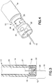
- Figure 3 shows the pen needle assembly 12 attached to the injector body 14 with the needle 20 inserted into the reservoir 16 at a location above the septum 18.
- the track 26 may be formed with two portions. With reference to Figure 4 , the injector body 14 with the track 26 having two portions is shown on a distal end 15 of the injector body 14. A first portion 28 of the track 26 extends proximally from the distal end 15 of the injector body 14, and a second portion 30 of the track 26 is disposed transversely to the first portion 28.
- Figure 4 further shows the pen needle assembly 12 containing the hub 22 with the needle 20 and the guide key 24 along an inner portion of the hub 22.
- the guide key 24 is a flange of limited length, which may be located on various portions of the hub 22. More particularly, the present invention contemplates the guide key 24 being located on the inner portion of the hub 22, as illustrated in Figure 4 , or on an outer portion of the hub 22, as illustrated in Figure 20 .
- the injector body 14 of Figure 4 is configured to enable the guide key 24 to be inserted into the first portion 28 of the track 26 and guided through the second portion 30 of the track 26. As shown in Figure 4 , more than one of the guide keys 24 may be provided, e.g., two, with a corresponding number of tracks 26 being provided.
- the guide keys 24 are discontinuous and evenly spaced.
- the pen needle assembly 12 is first inserted into the injector body 14 with the guide key 24 being accommodated in the first portion 28 of the track 26.
- the pen needle assembly 12 is guided in a straight line across a sufficient distance to permit the proximal end 21 of the needle 20 to fully pierce the septum 18 without rotation of the needle 20.
- the guide key 24 is received by the second portion 30 of the track 26.
- the second portion 30 of the track 26 is configured to permit the pen needle assembly 12 to be turned, while keeping the proximal end 21 of the needle 20 proximal to the septum 18.
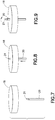
- Figures 7-9 further illustrate the phases of the needle 20 piercing the septum 18, as the pen needle assembly 12 is mounted onto the injector body 14 (described in Figures 5-6 ).
- Figure 7 shows the needle 20 and the septum 18 prior to the pen needle assembly 12 being mounted to the injector body 14.
- the needle 20 is first guided in a straight line across a sufficient distance to permit the proximal end 21 of the needle 20 to fully pierce the septum 18.
- the needle 20 is rotated, as shown in Figure 9 .
- the needle 20 is only rotated after the needle 20 fully pierces the septum 18 to prevent the sharp proximal 21 end of the needle 20 from coring the septum 18.
- the pen needle assembly as shown in Figures 1-9 may be placed on and off an injector freely.
- the medical injector 10 may contain a locking configuration 32 for locking the pen needle assembly 12 to the injector body 14.
- the locking configuration 32 may be releasable or permanent depending on the medical injector.
- Figure 10 shows a releasable lock 34 in the track 26 that enables the pen needle assembly 12 to be releasably locked to the injector body 14.
- the releasable lock 34 may include a ridge 33, preferably angled on both sides, creating a locking recess 35 in the second portion 30 of the track 26.
- the ridge 33 is located at the juncture between the first portion 28 and the second portion 30 of the track 26.
- the ridge 33 is formed such that the guide key 24 can move over both sides of the ridge 33 in moving in and out of the locking recess 35.
- the ridge 33 provides an obstruction, and thus provides a locking effect to the guide key 24 moving out from the locking recess 35.
- the hub 22 being of resilient material, deflection of the hub 22 permits the guide key 24 to traverse the ridge 33.
- the pen needle assembly 12 may be provided with an optional third portion 38 of the track 26.
- the third portion 38 of the track 26 traverses the second portion 30 of the track 26 and is designed to allow the needle 20 to move distally upon sufficient movement through the second portion 30.
- the third portion 38 is formed of limited length to ensure that the proximal end 21 of the needle 20 remains located proximally of the septum 18.
- Figure 13 shows the pen needle assembly 12 mounted with the guide key 24 in the optional third portion 38 of the track 26.
- a wall 29 is disposed between the first and third portions 28, 38 of the track 26 which prevents the guide key 24 from migrating to the first portion 26.
- the guide key 24 may be released from the third portion 38 by passage through the second portion 30 and traversal of the releasable lock 34.
- the third portion 38 may be used without the releasable lock 34 or other bodily arrangements.
- Figure 14 provides a further embodiment of the present invention with a tab 37 used to form a permanent tab lock 36 instead of the releasable lock 34 used in Figure 10 .
- the permanent tab lock 36 includes a tab 37 with an angled side 39 and an adjacent side 41 that is generally perpendicular to the track 26, with a locking recess 35 being defined on the adjacent side of the tab 37.
- Such a design enables the guide key 24 to be guided over the angled side 39 of the tab 37 engaging the permanent tab lock 36, but prevents the guide key 24 from moving back over the adjacent side 41 after being locked into the locking recess 35.
- the present invention also contemplates associating clicking noises with the locking configuration 32. More particularly, each releasable lock 34 or permanent tab lock 36 may create a clicking noise when engaged. Clicking noises with the locking configuration 32 may be a desirable feature because the clicking noise may provide assurance to the user that the pen needle 12 and injector body 14 are properly mounted and locked together. The clicking action may also provide tactile assurance of proper locking.
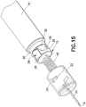
- Figure 15 shows a further embodiment of the medical injector 10 with an injector body 14 including a spring 40 and the third portion 38 of the track 26.
- This embodiment is similar to the arrangement shown in Figures 11-13 .
- manual movement is utilized to displace the guide key 24 in the third portion 38; and in this arrangement, the spring 40 provides a biasing force for urging the guide key 24 into the third portion 38.
- a locking arrangement (releasable or permanent) may be optionally utilized.
- Figures 16-17 show partial cross-sectional views of the embodiment of Figure 15 with the needle 20 in the second portion 30 of the track 26 ( Figure 16 ) and with the needle 20 in the third portion 38 of the track 26 ( Figure 17 ).
- the spring 40 causes the hub 22 to be displaced distally once the guide key 24 clears the wall 29, i.e., more sufficiently through the second portion 30.
- the spring 40 provides resistance against proximal movement of the hub 22 and, thus, enhances the locking effect applied to the hub 22.
- the guide key 24 located on an inner portion of the hub 22. As shown in Figures 18-26 , the guide key 24 may also be located on an outer portion of the hub 22. With the guide key 24 being on an outer portion of the hub 22, the injector body 14 may be formed to at least partially encase the hub 22.
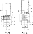
- Figures 18-20 show an embodiment similar to that shown in Figures 15-17 , except that the guide key 24 is located on the outer portion of the hub 22 and that the injector body 14 defines the track 26 exteriorly of the hub 22. More specifically, Figures 18-19 show partial cross-sectional views of the pen needle assembly 12 with the guide key 24 located on the outer portion of the hub 22.
- Figures 16 and 18 show the present invention after the proximal end 21 of the needle 20 fully pierces the septum 18 on the first portion 28 of the track 26. Afterwards the needle 20 is rotated and then moved distally along the third portion 38 of the track 26, with the proximal end 21 of the needle 20 remaining proximal to the septum 18, as shown in Figures 17 and 19 .
- Figures 20-25 show the pen needle assembly 12 of the present invention with the guide key 24 disposed on an outer portion of the hub 22 prior to being mounted onto the distal end 15 of the injector body 14.
- the injector body 14 may be formed to have the track 26 defined externally and the guide key 24 may be located on the outer portion of the hub 22.
- the track 26 may be formed as a channel of limited depth, as shown in previous figures or be a through hole through the injector body 14, as shown in Figures 20-26 .
- the track 26 may be configured using a combination of the arrangements provided herein.
- Figures 21-22 the guide key 24 and the track 26 are aligned such that the first portion 28 of the track 26 receives the guide key 24.
- Figure 23 shows the guide key 24 and track 26 after the pen needle assembly 12 is partially guided through the second portion 30 of the track 26. Then, in Figure 24 , the guide key 24 is in the third portion 38 of the track 26. Finally, Figure 25 shows the guide key 24 in a locked position in the third portion 38 with the wall 29 separating the guide key 24 from the first portion 28.
- the spring 40 may be utilized, as described above, to bias the pen needle assembly 12 distally.
- the second portion 30 of the track 26 may be angularly disposed relative to the first portion 28 of the track 26.
- the second portion 30 of the track 26 is generally perpendicular to the first portion 28 of the track 26.
- the guide key 24 is rotated after the guide key 24 sufficiently traverses the first portion 28 of the track 26 to reach the second portion 30 of the track 26.
- the guide key 24 is forced to rotate as it traverses the second portion 30 of the track 26. Therefore, the first portion 28 of the track 26 must be provided with sufficient length to ensure that the proximal end 21 of the needle 20 completely pierces the septum 18 before entering the second portion 30 of the track 26 and being rotated.
- the second portion 30 may also be angularly disposed (perpendicular or at some other transverse position) to the third portion 38 of the track 26.
- the first portion 28 of the track 26 and the third portion 38 of the track 26 are generally parallel.
- a deflectable latch 42 may be utilized which is by-passed by the guide key 24 as traversing through the third portion 38 of the track 26.
- the latch 42 may be formed to be by-passed in both directions along the third portion 38 by the guide key 24 (i.e., in and out of the locking portion) in providing a releasable locking arrangement, or may be formed to be by-passed only in one direction (i.e., into the locking position) in providing a permanent one-time locking arrangement.
- Figure 26 provides a further feature of the present invention with the track 26 located on the hub 22, instead of the injector body 14, and the guide key 24 located on the injector body 14, instead of the hub 22.
- the locking configuration 32 would allow the locking configuration 32 to include the track 26 and the locking recess 35 located on the hub 22 and the guide key 24 located on the injector body 14.
- a cap 44 to accommodate the pen needle assembly 12 before and/or after use is shown.
- the cap 44 is designed to cover both the proximal and distal ends 19, 21 of the needle 20 in the pen needle assembly 12 and may be used with, but is not limited to the embodiments disclosed herein.
- the cap 44 is provided with an opening 46 for receiving the pen needle assembly 12. Before use, and to maintain an internal sterile environment, the opening 46 may be covered by a closure (not shown), which may be a rigid cap or flexible backing.
- the closure may be applied using standard techniques, such as a mechanical connector (e.g., threads, interference fit) or adherent connection.
Landscapes
- Health & Medical Sciences (AREA)
- Vascular Medicine (AREA)
- Engineering & Computer Science (AREA)
- Anesthesiology (AREA)
- Biomedical Technology (AREA)
- Heart & Thoracic Surgery (AREA)
- Hematology (AREA)
- Life Sciences & Earth Sciences (AREA)
- Animal Behavior & Ethology (AREA)
- General Health & Medical Sciences (AREA)
- Public Health (AREA)
- Veterinary Medicine (AREA)
- Infusion, Injection, And Reservoir Apparatuses (AREA)
Abstract
Description
- This invention relates to pen needle assemblies for pen injectors.
- Pen needle assemblies are known in the prior art for use with pen injectors. Pen needle assemblies are individually provided for a pen injector and include a hub attached to a needle. Typically, the assemblies are formed to be removably mounted to the pen injector and disposed after use. With multiple-dose pen injectors, a plurality of pen needle assemblies are mounted and removed from the injector.
- The needles used with pen needle assemblies are of limited length. The needles must have sufficient proximal length to pierce a septum of a medicament reservoir and have sufficient distal length to be inserted into a patient for a medical injection. Prior art pen assembly designs have been found to cause "tenting" of a drug reservoir septum when the proximal part of the needle does not sufficiently pass through the septum. As such, the septum may not be fully penetrated or the septum is distorted resulting in possible incorrect drug administration. An overly-sized proximal portion of the needle may be used to avoid "tenting." However, an excessively long needle in the proximal direction may not efficiently convey medicament from low levels in a drug reservoir.
- Additionally, pen needle assemblies are typically attached to the pen injector by rotating the needle, while inserting the needle into the septum of a medicament reservoir. The combined rotating and traversing motion of the needle may cause coring of the septum. The septum is formed to be resealable upon removable of the pen needle assembly. With a cored septum, a portion of the septum may not be resealable, resulting in the need to dispose of the reservoir.
- A pen needle assembly is provided herein for use with a medical injector. The pen needle assembly includes a hub and a needle fixed to the hub. The needle has a distal end, formed for insertion into a patient, and a proximal end. The medical injector further includes an injector body being tubular in shape with a distal end and a proximal end and a reservoir sealed by a septum encased in the injector body. The hub is formed to be telescopingly mounted onto the distal end of the injector body using a track that accommodates a guide key. When mounting the pen needle assembly onto the injector body, a first portion of the track is configured to receive the guide key and to guide the guide key in a straight line across sufficient distance to permit the proximal end of the needle to fully pierce through the septum, without rotation of the needle and with the proximal end of the needle being guided to a location proximal of the septum. A second portion of the track is configured to permit the pen needle assembly to be turned with the guide key being received in the second portion of the track with the proximal end of the needle being located proximally of the septum. Advantageously, with the arrangement of the subject invention, coring of a drug cartridge septum may be generally avoided with repeated mounting of pen needle assemblies onto the medical injector.
- These and other features of the invention will be better understood through a study of the following detailed description and accompanying drawings.
-
-
Figure 1 depicts an exploded view of a medical injector formed in accordance with the present invention; -
Figure 2 depicts an assembled view of a medical injector formed in accordance with the present invention; -
Figure 3 depicts a partial cross-section of a medical injector of a first embodiment of a pen needle assembly of the present invention; -
Figures 4-6 depict different stages of a pen needle assembly being mounted to an injector body; -
Figures 7-9 depict a needle of the pen needle assembly formed in accordance with the subject invention prior to, during, and after piercing the septum; -
Figures 10-14 depict a pen needle assembly of the first embodiment of the present invention with various locking configurations; -
Figures 15-17 depict a pen needle assembly of a second embodiment of the present invention; -
Figures 18-26 depict a variation of the second embodiment of the present invention with a guide key fixed to an outer portion of a hub; and -
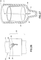
Figure 27 depicts a pen needle assembly of the present invention with a cap surrounding the assembly. - With reference to the Figures, a
medical injector 10 is provided herein. Themedical injector 10 may be of various injector configurations. The present invention is well-suited with themedical injector 10 being a pen injector. - As shown in
Figures 1-3 , themedical injector 10 generally includes: apen needle assembly 12; aninjector body 14, including adistal end 15 and aproximal end 17; and areservoir 16 for medicament sealed by aseptum 18. Thereservoir 16 is encased within theinjector body 14 and may be defined by theinjector body 14 or defined by a separate component contained within the injector body 14 (e.g., a cartridge). - The
pen needle assembly 12 further includes aneedle 20 and ahub 22. Theneedle 20 includes adistal end 19, formed for insertion into a patient, and aproximal end 21. Theassembly 12 is configured to guide theneedle 20 in a straight line to permit theproximal end 21 of theneedle 20 to fully pierce through theseptum 18 without rotation of theneedle 20. To obtain this configuration, aguide key 24 is provided on one of thehub 22 or theinjector body 14 with atrack 26 being defined on the other of thehub 22 or theinjector body 14. It is preferred that theguide key 24 be formed on thehub 22 and that thetrack 26 be defined on theinjector body 14. -
Figure 3 shows thepen needle assembly 12 attached to theinjector body 14 with theneedle 20 inserted into thereservoir 16 at a location above theseptum 18. - The
track 26 may be formed with two portions. With reference toFigure 4 , theinjector body 14 with thetrack 26 having two portions is shown on adistal end 15 of theinjector body 14. Afirst portion 28 of thetrack 26 extends proximally from thedistal end 15 of theinjector body 14, and asecond portion 30 of thetrack 26 is disposed transversely to thefirst portion 28. -
Figure 4 further shows thepen needle assembly 12 containing thehub 22 with theneedle 20 and theguide key 24 along an inner portion of thehub 22. Theguide key 24 is a flange of limited length, which may be located on various portions of thehub 22. More particularly, the present invention contemplates theguide key 24 being located on the inner portion of thehub 22, as illustrated inFigure 4 , or on an outer portion of thehub 22, as illustrated inFigure 20 . Theinjector body 14 ofFigure 4 is configured to enable theguide key 24 to be inserted into thefirst portion 28 of thetrack 26 and guided through thesecond portion 30 of thetrack 26. As shown inFigure 4 , more than one of theguide keys 24 may be provided, e.g., two, with a corresponding number oftracks 26 being provided. Theguide keys 24 are discontinuous and evenly spaced. - With reference to
Figures 5-6 , during use, thepen needle assembly 12 is first inserted into theinjector body 14 with theguide key 24 being accommodated in thefirst portion 28 of thetrack 26. As thefirst portion 28 of thetrack 26 receives theguide key 24, thepen needle assembly 12 is guided in a straight line across a sufficient distance to permit theproximal end 21 of theneedle 20 to fully pierce theseptum 18 without rotation of theneedle 20. Once theproximal end 21 of theneedle 20 is guided a sufficient distance proximal to theseptum 18, theguide key 24 is received by thesecond portion 30 of thetrack 26. Thesecond portion 30 of thetrack 26 is configured to permit thepen needle assembly 12 to be turned, while keeping theproximal end 21 of theneedle 20 proximal to theseptum 18. -
Figures 7-9 further illustrate the phases of theneedle 20 piercing theseptum 18, as thepen needle assembly 12 is mounted onto the injector body 14 (described inFigures 5-6 ).Figure 7 shows theneedle 20 and theseptum 18 prior to thepen needle assembly 12 being mounted to theinjector body 14. With reference toFigure 8 , when piercing theseptum 18, theneedle 20 is first guided in a straight line across a sufficient distance to permit theproximal end 21 of theneedle 20 to fully pierce theseptum 18. Then, after theneedle 20 fully pierces theseptum 18, theneedle 20 is rotated, as shown inFigure 9 . Theneedle 20 is only rotated after theneedle 20 fully pierces theseptum 18 to prevent the sharp proximal 21 end of theneedle 20 from coring theseptum 18. - The pen needle assembly as shown in
Figures 1-9 may be placed on and off an injector freely. - With reference to
Figures 10-14 , themedical injector 10 may contain a lockingconfiguration 32 for locking thepen needle assembly 12 to theinjector body 14. The lockingconfiguration 32 may be releasable or permanent depending on the medical injector.Figure 10 shows areleasable lock 34 in thetrack 26 that enables thepen needle assembly 12 to be releasably locked to theinjector body 14. Thereleasable lock 34 may include aridge 33, preferably angled on both sides, creating a lockingrecess 35 in thesecond portion 30 of thetrack 26. Preferably, theridge 33 is located at the juncture between thefirst portion 28 and thesecond portion 30 of thetrack 26. Theridge 33 is formed such that the guide key 24 can move over both sides of theridge 33 in moving in and out of the lockingrecess 35. Theridge 33 provides an obstruction, and thus provides a locking effect to theguide key 24 moving out from the lockingrecess 35. With thehub 22 being of resilient material, deflection of thehub 22 permits the guide key 24 to traverse theridge 33. - To further enhance the locking effect, as illustrated in
Figures 11-13 , thepen needle assembly 12 may be provided with an optionalthird portion 38 of thetrack 26. Thethird portion 38 of thetrack 26 traverses thesecond portion 30 of thetrack 26 and is designed to allow theneedle 20 to move distally upon sufficient movement through thesecond portion 30. Thethird portion 38 is formed of limited length to ensure that theproximal end 21 of theneedle 20 remains located proximally of theseptum 18. - During use, after the
guide key 24 is received by thefirst portion 28, as shown inFigure 11 , thepen needle assembly 12 is rotated along thesecond portion 30 of thetrack 26 until thereleasable lock 34 is engaged, as shown inFigure 12 . To further enhance the locking effect,Figure 13 shows thepen needle assembly 12 mounted with the guide key 24 in the optionalthird portion 38 of thetrack 26. Awall 29 is disposed between the first andthird portions track 26 which prevents the guide key 24 from migrating to thefirst portion 26. Theguide key 24 may be released from thethird portion 38 by passage through thesecond portion 30 and traversal of thereleasable lock 34. As will be appreciated by those skilled in the art, thethird portion 38 may be used without thereleasable lock 34 or other bodily arrangements. -
Figure 14 provides a further embodiment of the present invention with atab 37 used to form apermanent tab lock 36 instead of thereleasable lock 34 used inFigure 10 . Thepermanent tab lock 36 includes atab 37 with anangled side 39 and anadjacent side 41 that is generally perpendicular to thetrack 26, with a lockingrecess 35 being defined on the adjacent side of thetab 37. Such a design enables the guide key 24 to be guided over theangled side 39 of thetab 37 engaging thepermanent tab lock 36, but prevents the guide key 24 from moving back over theadjacent side 41 after being locked into the lockingrecess 35. - The present invention also contemplates associating clicking noises with the locking
configuration 32. More particularly, eachreleasable lock 34 orpermanent tab lock 36 may create a clicking noise when engaged. Clicking noises with the lockingconfiguration 32 may be a desirable feature because the clicking noise may provide assurance to the user that thepen needle 12 andinjector body 14 are properly mounted and locked together. The clicking action may also provide tactile assurance of proper locking. -
Figure 15 shows a further embodiment of themedical injector 10 with aninjector body 14 including aspring 40 and thethird portion 38 of thetrack 26. This embodiment is similar to the arrangement shown inFigures 11-13 . With the embodiment ofFigures 11-13 , manual movement is utilized to displace the guide key 24 in thethird portion 38; and in this arrangement, thespring 40 provides a biasing force for urging the guide key 24 into thethird portion 38. A locking arrangement (releasable or permanent) may be optionally utilized. -
Figures 16-17 show partial cross-sectional views of the embodiment ofFigure 15 with theneedle 20 in thesecond portion 30 of the track 26 (Figure 16 ) and with theneedle 20 in thethird portion 38 of the track 26 (Figure 17 ). Thespring 40 causes thehub 22 to be displaced distally once theguide key 24 clears thewall 29, i.e., more sufficiently through thesecond portion 30. Thespring 40 provides resistance against proximal movement of thehub 22 and, thus, enhances the locking effect applied to thehub 22. - The previous figures show the guide key 24 located on an inner portion of the
hub 22. As shown inFigures 18-26 , theguide key 24 may also be located on an outer portion of thehub 22. With theguide key 24 being on an outer portion of thehub 22, theinjector body 14 may be formed to at least partially encase thehub 22. -
Figures 18-20 show an embodiment similar to that shown inFigures 15-17 , except that theguide key 24 is located on the outer portion of thehub 22 and that theinjector body 14 defines thetrack 26 exteriorly of thehub 22. More specifically,Figures 18-19 show partial cross-sectional views of thepen needle assembly 12 with the guide key 24 located on the outer portion of thehub 22.Figures 16 and18 show the present invention after theproximal end 21 of theneedle 20 fully pierces theseptum 18 on thefirst portion 28 of thetrack 26. Afterwards theneedle 20 is rotated and then moved distally along thethird portion 38 of thetrack 26, with theproximal end 21 of theneedle 20 remaining proximal to theseptum 18, as shown inFigures 17 and 19 . -
Figures 20-25 show thepen needle assembly 12 of the present invention with the guide key 24 disposed on an outer portion of thehub 22 prior to being mounted onto thedistal end 15 of theinjector body 14. Here, theinjector body 14 may be formed to have thetrack 26 defined externally and theguide key 24 may be located on the outer portion of thehub 22. Thetrack 26 may be formed as a channel of limited depth, as shown in previous figures or be a through hole through theinjector body 14, as shown inFigures 20-26 . As one skilled in the art would appreciate, thetrack 26 may be configured using a combination of the arrangements provided herein. - In
Figures 21-22 , theguide key 24 and thetrack 26 are aligned such that thefirst portion 28 of thetrack 26 receives theguide key 24.Figure 23 shows theguide key 24 andtrack 26 after thepen needle assembly 12 is partially guided through thesecond portion 30 of thetrack 26. Then, inFigure 24 , theguide key 24 is in thethird portion 38 of thetrack 26. Finally,Figure 25 shows the guide key 24 in a locked position in thethird portion 38 with thewall 29 separating the guide key 24 from thefirst portion 28. Optionally, thespring 40 may be utilized, as described above, to bias thepen needle assembly 12 distally. - As shown in the figures, the
second portion 30 of thetrack 26 may be angularly disposed relative to thefirst portion 28 of thetrack 26. With the arrangement ofFigure 24 , thesecond portion 30 of thetrack 26 is generally perpendicular to thefirst portion 28 of thetrack 26. As such, theguide key 24 is rotated after the guide key 24 sufficiently traverses thefirst portion 28 of thetrack 26 to reach thesecond portion 30 of thetrack 26. With the angled arrangement ofFigure 25 , theguide key 24 is forced to rotate as it traverses thesecond portion 30 of thetrack 26. Therefore, thefirst portion 28 of thetrack 26 must be provided with sufficient length to ensure that theproximal end 21 of theneedle 20 completely pierces theseptum 18 before entering thesecond portion 30 of thetrack 26 and being rotated. - The
second portion 30 may also be angularly disposed (perpendicular or at some other transverse position) to thethird portion 38 of thetrack 26. In a preferred arrangement, thefirst portion 28 of thetrack 26 and thethird portion 38 of thetrack 26 are generally parallel. - As shown in
Figure 25 , various forms of the lockingconfigurations 32 may be utilized. For example, adeflectable latch 42 may be utilized which is by-passed by the guide key 24 as traversing through thethird portion 38 of thetrack 26. As appreciated by those skilled in the art, thelatch 42 may be formed to be by-passed in both directions along thethird portion 38 by the guide key 24 (i.e., in and out of the locking portion) in providing a releasable locking arrangement, or may be formed to be by-passed only in one direction (i.e., into the locking position) in providing a permanent one-time locking arrangement. -
Figure 26 provides a further feature of the present invention with thetrack 26 located on thehub 22, instead of theinjector body 14, and the guide key 24 located on theinjector body 14, instead of thehub 22. As one skilled in the art will appreciate, all configurations and features discussed above are useable with this arrangement. For example, an alternative configuration would allow the lockingconfiguration 32 to include thetrack 26 and the lockingrecess 35 located on thehub 22 and the guide key 24 located on theinjector body 14. - With reference to
Figure 27 , acap 44 to accommodate thepen needle assembly 12 before and/or after use is shown. Thecap 44 is designed to cover both the proximal and distal ends 19, 21 of theneedle 20 in thepen needle assembly 12 and may be used with, but is not limited to the embodiments disclosed herein. Thecap 44 is provided with anopening 46 for receiving thepen needle assembly 12. Before use, and to maintain an internal sterile environment, theopening 46 may be covered by a closure (not shown), which may be a rigid cap or flexible backing. The closure may be applied using standard techniques, such as a mechanical connector (e.g., threads, interference fit) or adherent connection.
Claims (15)
- A medical injector comprising:a pen needle (20) assembly (12) including:a hub (22);a needle (20) fixed to said hub (22), said needle (20) having a distal end (19), formed for insertion into a patient, and a proximal end (21);an injector body (14) being tubular in shape with a distal end (15) and a proximal end (17); anda reservoir (16) for medicament sealed by a septum (18), said reservoir (16) being encased in said injector body;wherein, a guide key (24) is fixed to one of said hub (22) or said injector body (14), a track (26) being defined on the other of said hub (22) or said injector body (14), said track (26) having a first portion (28) extending parallel to a longitudinal axis of said injector body (14) and a second portion (30) disposed at an angle to said first portion (28); and, wherein, said hub (22) is formed to be telescopingly mounted onto said distal end (15) of said injector body (14) with said guide key (24) being accommodated in said track (26), and wherein, with mounting said hub (22) of said pen needle (20) assembly (12) onto said injector body, said first portion (28) of said track (26) being configured to receive said guide key (24) and to guide said guide key (24) in a straight line across sufficient distance to permit said proximal end (21) of said needle (20) to fully pierce through said septum (18) without rotation of said needle (20), said proximal end (21) of said needle (20) being guided to a location proximal of said septum (18), and said second portion (30) of said track (26) being configured to permit said pen needle (20) assembly (12) to be turned with said guide key (24) being received in said second portion (30) of said track (26) with said proximal end (21) of said needle (20) being located proximally of said septum (18).
- A medical injector of claim 1, wherein said track (26) is located on said hub (22).
- A medical injector of claim 1, wherein said track (26) is located on said injector body (14).
- A medical injector of claim 3, wherein said first portion (28) of said track (26) extends proximally from said distal end (15) of said injector body (14).
- A medical injector of claim 1, wherein said track (26) further having a third portion (38) disposed at an angle to said second portion (30) of said track.
- A medical injector of claim 5, further comprising a spring (40) disposed between said injector body (14) and said hub (22), said spring (40) configured to bias said hub (22) distally away from said injector body, whereas said spring (40) urges said guide key (24) into said third portion (38) of said track (26) with said guide key (24) being sufficiently moved through said second portion (30) of said track (26).
- A medical injector of claim 1 further comprising a locking means for locking said guide key (24) in said track (26).
- A medical injector of claim 7, wherein said locking means includes at least one locking recess (35) and said guide key (24) is formed to be received and secured in said locking recess.
- A medical injector of claim 8, wherein said locking recess (35) is formed in said track (26) of said hub (22) and said guide key (24) is formed on said injector body (14).
- A medical injector of claim 8, wherein said locking recess (35) is formed in said track (26) of said injector body (14) and said guide key (24) is formed on said hub (22).
- A medical injector of claim 7, wherein said locking means comprises a releasable lock (34) comprising:a ridge (33) having two angled sides and being located in said track (26); andsaid guide key (24),wherein said guide key (24) is configured to slide over one of said angled sides of said ridge (33) when said hub (22) and said injector body (14) are connected, and wherein said guide key (24) is configured to slide over the other of said angled side of said ridge (33) when said hub (22) and said injector body (14) are disconnected.
- A medical injector of claim 7, wherein said locking means comprises a permanent lock (36) comprising:a tab (37) being located in said track (26) and comprising an angled side (39) and an adjacent side (41) that is generally perpendicular to said track (26); andsaid guide key (24),wherein said guide key (24) is configured to be guided over said angled side (39) of said tab (37) when said hub (22) and said injector body (14) are connected, and wherein said adjacent side (41) of said tab (37) prevents said guide key from passing thereover, and prevents said hub (22) from being disconnected from said injector body (14).
- A medical injector of claim 11 or claim 12, wherein said locking means provides an audible and/or tactile indication of locking.
- A medical injector of claim 1, wherein the injector comprises a plurality of guide keys (24) and a corresponding number of tracks (26).
- A kit comprising:a medical injector, as set forth in claim 1; anda cap formed to accommodate said pen needle (20) assembly (12).
Applications Claiming Priority (3)
| Application Number | Priority Date | Filing Date | Title |
|---|---|---|---|
| US1113608P | 2008-01-15 | 2008-01-15 | |
| PCT/US2009/030798 WO2009091707A1 (en) | 2008-01-15 | 2009-01-13 | Medical injector with pen needle assembly |
| EP09702236.2A EP2240225B1 (en) | 2008-01-15 | 2009-01-13 | Medical injector with pen needle assembly |
Related Parent Applications (2)
| Application Number | Title | Priority Date | Filing Date |
|---|---|---|---|
| EP09702236.2A Division-Into EP2240225B1 (en) | 2008-01-15 | 2009-01-13 | Medical injector with pen needle assembly |
| EP09702236.2A Division EP2240225B1 (en) | 2008-01-15 | 2009-01-13 | Medical injector with pen needle assembly |
Publications (3)
| Publication Number | Publication Date |
|---|---|
| EP3153198A1 true EP3153198A1 (en) | 2017-04-12 |
| EP3153198C0 EP3153198C0 (en) | 2024-04-17 |
| EP3153198B1 EP3153198B1 (en) | 2024-04-17 |
Family
ID=40524598
Family Applications (2)
| Application Number | Title | Priority Date | Filing Date |
|---|---|---|---|
| EP09702236.2A Active EP2240225B1 (en) | 2008-01-15 | 2009-01-13 | Medical injector with pen needle assembly |
| EP16190660.7A Active EP3153198B1 (en) | 2008-01-15 | 2009-01-13 | Medical injector with pen needle assembly |
Family Applications Before (1)
| Application Number | Title | Priority Date | Filing Date |
|---|---|---|---|
| EP09702236.2A Active EP2240225B1 (en) | 2008-01-15 | 2009-01-13 | Medical injector with pen needle assembly |
Country Status (6)
| Country | Link |
|---|---|
| US (1) | US8241257B2 (en) |
| EP (2) | EP2240225B1 (en) |
| JP (1) | JP5451638B2 (en) |
| CN (1) | CN101945681B (en) |
| ES (1) | ES2618360T3 (en) |
| WO (1) | WO2009091707A1 (en) |
Families Citing this family (30)
| Publication number | Priority date | Publication date | Assignee | Title |
|---|---|---|---|---|
| US7654986B2 (en) | 2002-07-03 | 2010-02-02 | Novo Nordisk A/S | Needle mounting system and a method for mounting a needle assembly |
| US7871397B2 (en) | 2006-12-26 | 2011-01-18 | Stat Medical Devices, Inc. | Pen needle tip |
| USD675316S1 (en) | 2007-08-22 | 2013-01-29 | Novo Nordisk A/S | Needle hub |
| CN102413858B (en) * | 2009-03-03 | 2017-03-01 | 贝克顿·迪金森公司 | For transmitting the pen type needle assembly of drug solution |
| US20110023281A1 (en) * | 2009-04-30 | 2011-02-03 | Stat Medical Devices, Inc. | Pen injection device cap with integral pen needle quick release and/or removal system |
| US9700681B2 (en) * | 2009-05-15 | 2017-07-11 | Stat Medical Devices, Inc. | Pen needle with quick release and/or removal system |
| JP5843870B2 (en) * | 2010-10-01 | 2016-01-13 | サノフィ−アベンティス・ドイチュラント・ゲゼルシャフト・ミット・ベシュレンクテル・ハフツング | Needle assembly with release mechanism |
| US10463803B2 (en) | 2010-11-12 | 2019-11-05 | Stat Medical Devices, Inc. | Pen needle with quick release and/or removal system |
| US8961470B2 (en) | 2011-02-17 | 2015-02-24 | Steven Schraga | Pen needle with safety shield system |
| JP2014516703A (en) * | 2011-05-25 | 2014-07-17 | サノフィ−アベンティス・ドイチュラント・ゲゼルシャフト・ミット・ベシュレンクテル・ハフツング | Eject button for drug delivery device |
| US9078978B2 (en) | 2011-12-28 | 2015-07-14 | Stat Medical Devices, Inc. | Needle assembly with safety system for a syringe or fluid sampling device and method of making and using the same |
| CN102520076B (en) * | 2011-12-31 | 2013-07-17 | 青岛普仁仪器有限公司 | Automatic sample injector |
| MX2014008747A (en) | 2012-01-20 | 2014-08-27 | Lk Medical Co Ltd | Disposable syringe. |
| CN104519928B (en) * | 2012-04-05 | 2017-09-22 | 赛诺菲-安万特德国有限公司 | pen-type injector |
| US10517519B2 (en) * | 2012-08-31 | 2019-12-31 | Terumo Kabushiki Kaisha | Blood sampling device and blood bag system |
| USD770043S1 (en) * | 2013-10-29 | 2016-10-25 | Htl-Strefa Spolka Akcyjna | Needle hub |
| JP6282441B2 (en) * | 2013-11-05 | 2018-02-21 | 大成化工株式会社 | Nozzle replaceable drug injector |
| WO2015160600A1 (en) * | 2014-04-15 | 2015-10-22 | Min Wei | Medication delivery device |
| US10118000B2 (en) | 2014-04-21 | 2018-11-06 | Stat Medical Devices, Inc. | Pen needle installation and removal safety cover and pen needle assembly utilizing the same |
| US10155091B2 (en) | 2014-07-11 | 2018-12-18 | Stat Medical Devices, Inc. | Pen needle tip and method of making and using the same |
| US11033683B2 (en) | 2015-11-27 | 2021-06-15 | Sanofi-Aventis Deutschland Gmbh | Medicament injection device |
| JP6924756B2 (en) | 2015-11-27 | 2021-08-25 | サノフィ−アベンティス・ドイチュラント・ゲゼルシャフト・ミット・ベシュレンクテル・ハフツング | Drug delivery device with cap |
| USD787054S1 (en) | 2016-04-14 | 2017-05-16 | Becton, Dickinson And Company | Pen needle hub |
| WO2017189172A1 (en) * | 2016-04-28 | 2017-11-02 | Becton, Dickinson And Company | Needle storage magazine assembly |
| CN109196569A (en) * | 2016-06-08 | 2019-01-11 | 艾斯曲尔医疗公司 | Drug administration mechanism for medicament conveying training device |
| WO2020112113A1 (en) * | 2018-11-29 | 2020-06-04 | Becton, Dickinson And Company | Pen and pen needle adapter with feature to improve access to packaged needle assembly |
| EP3958933A4 (en) * | 2019-04-26 | 2022-11-23 | Embecta Corp. | PIN ARRANGEMENT |
| EP4606404A3 (en) * | 2019-09-11 | 2025-11-05 | Eli Lilly and Company | Medication delivery device with needle carrier |
| CN113288141B (en) * | 2021-06-28 | 2022-07-01 | 吉林大学第一医院 | Lancet device capable of separating a lancet |
| US20240148986A1 (en) * | 2022-11-07 | 2024-05-09 | Becton, Dickinson And Company | Reuse Prevention Flush Syringe |
Citations (11)
| Publication number | Priority date | Publication date | Assignee | Title |
|---|---|---|---|---|
| GB836278A (en) * | 1957-05-02 | 1960-06-01 | American Home Prod | Cartridge needle unit |
| US4449539A (en) * | 1980-12-30 | 1984-05-22 | Walter Sarstedt Kunstoff-Spritzgusswerk | Blood extraction device |
| US4731059A (en) * | 1986-10-14 | 1988-03-15 | Medical Safety Products, Inc. | Combination needle shield/needle guard device positively locked onto detachable needle assemblies for an evacuated blood collection system and a hypodermic syringe |
| EP0704225A2 (en) * | 1994-09-28 | 1996-04-03 | Becton, Dickinson and Company | Retractable needle syringe |
| WO1996011028A1 (en) * | 1994-10-11 | 1996-04-18 | Ian Marshall Moore | Single use syringe |
| US6200296B1 (en) * | 1996-09-26 | 2001-03-13 | Becton Dickinson And Company | 5mm injection needle |
| WO2001091837A1 (en) * | 2000-05-31 | 2001-12-06 | Novo Nordisk A/S | A disposable double pointed injection needle, and an insulin injection system comprising a disposable double pointed injection needle |
| US20040147855A1 (en) * | 2003-01-23 | 2004-07-29 | Becton, Dickinson And Company | Coupling device for blood collection assembly |
| US20050113750A1 (en) * | 2003-11-21 | 2005-05-26 | Targell David J. | Safety needle |
| WO2006103074A1 (en) * | 2005-03-31 | 2006-10-05 | Covidien Ag | Connector for medical applications |
| FR2884723A1 (en) * | 2005-04-20 | 2006-10-27 | Becton Dickinson France Soc Pa | Injection needle protector with support, sleeve and spring has axial guides to prevent sleeve from rotating as it moves axially relative to support |
Family Cites Families (17)
| Publication number | Priority date | Publication date | Assignee | Title |
|---|---|---|---|---|
| US836278A (en) * | 1905-02-27 | 1906-11-20 | George H D Ross | Ditch-dam. |
| US2828742A (en) * | 1957-05-02 | 1958-04-01 | American Home Prod | Cartridge-needle unit |
| US5505694A (en) * | 1990-08-22 | 1996-04-09 | Tcnl Technologies, Inc. | Apparatus and method for raising a skin wheal |
| US5829589A (en) * | 1997-09-12 | 1998-11-03 | Becton Dickinson And Company | Pen needle magazine dispenser |
| US5941857A (en) * | 1997-09-12 | 1999-08-24 | Becton Dickinson And Company | Disposable pen needle |
| US5873462A (en) * | 1997-09-12 | 1999-02-23 | Becton Dickinson And Company | Pen needle dispenser |
| US5931817A (en) * | 1997-09-12 | 1999-08-03 | Becton Dickinson And Company | Pen needle assembly |
| US5944700A (en) * | 1997-09-26 | 1999-08-31 | Becton, Dickinson And Company | Adjustable injection length pen needle |
| US6017331A (en) * | 1998-02-20 | 2000-01-25 | Becton Dickinson And Company | Threaded medication cartridge |
| US6346094B2 (en) * | 1998-09-28 | 2002-02-12 | Becton, Dickinson And Company | Pen needle magazine |
| US6986760B2 (en) * | 2000-08-02 | 2006-01-17 | Becton, Dickinson And Company | Pen needle and safety shield system |
| US6595960B2 (en) * | 2001-04-12 | 2003-07-22 | Becton, Dickinson And Company | Flexible needle assembly |
| US7540858B2 (en) * | 2007-01-23 | 2009-06-02 | Becton, Dickinson And Company | Retracting safety pen needle |
| US7462169B2 (en) * | 2007-01-23 | 2008-12-09 | Becton, Dickinson And Company | Safety shield system for an injection pen needle |
| US7462168B2 (en) * | 2007-01-23 | 2008-12-09 | Becton, Dickinson And Company | Safety pen needle with passive safety shield system |
| CA2639320C (en) * | 2007-09-07 | 2016-10-25 | Becton, Dickinson And Company | Pen-needle assembly for preventing under-torquing and over-torquing of pen-needle |
| CN101945680B (en) * | 2008-01-15 | 2013-08-21 | 贝克顿·迪金森公司 | Pen needle assembly with needle insertion mechanism |
-
2009
- 2009-01-13 US US12/863,093 patent/US8241257B2/en active Active
- 2009-01-13 EP EP09702236.2A patent/EP2240225B1/en active Active
- 2009-01-13 JP JP2010543180A patent/JP5451638B2/en active Active
- 2009-01-13 ES ES09702236.2T patent/ES2618360T3/en active Active
- 2009-01-13 CN CN2009801054612A patent/CN101945681B/en active Active
- 2009-01-13 WO PCT/US2009/030798 patent/WO2009091707A1/en not_active Ceased
- 2009-01-13 EP EP16190660.7A patent/EP3153198B1/en active Active
Patent Citations (11)
| Publication number | Priority date | Publication date | Assignee | Title |
|---|---|---|---|---|
| GB836278A (en) * | 1957-05-02 | 1960-06-01 | American Home Prod | Cartridge needle unit |
| US4449539A (en) * | 1980-12-30 | 1984-05-22 | Walter Sarstedt Kunstoff-Spritzgusswerk | Blood extraction device |
| US4731059A (en) * | 1986-10-14 | 1988-03-15 | Medical Safety Products, Inc. | Combination needle shield/needle guard device positively locked onto detachable needle assemblies for an evacuated blood collection system and a hypodermic syringe |
| EP0704225A2 (en) * | 1994-09-28 | 1996-04-03 | Becton, Dickinson and Company | Retractable needle syringe |
| WO1996011028A1 (en) * | 1994-10-11 | 1996-04-18 | Ian Marshall Moore | Single use syringe |
| US6200296B1 (en) * | 1996-09-26 | 2001-03-13 | Becton Dickinson And Company | 5mm injection needle |
| WO2001091837A1 (en) * | 2000-05-31 | 2001-12-06 | Novo Nordisk A/S | A disposable double pointed injection needle, and an insulin injection system comprising a disposable double pointed injection needle |
| US20040147855A1 (en) * | 2003-01-23 | 2004-07-29 | Becton, Dickinson And Company | Coupling device for blood collection assembly |
| US20050113750A1 (en) * | 2003-11-21 | 2005-05-26 | Targell David J. | Safety needle |
| WO2006103074A1 (en) * | 2005-03-31 | 2006-10-05 | Covidien Ag | Connector for medical applications |
| FR2884723A1 (en) * | 2005-04-20 | 2006-10-27 | Becton Dickinson France Soc Pa | Injection needle protector with support, sleeve and spring has axial guides to prevent sleeve from rotating as it moves axially relative to support |
Also Published As
| Publication number | Publication date |
|---|---|
| US20110106016A1 (en) | 2011-05-05 |
| EP3153198C0 (en) | 2024-04-17 |
| US8241257B2 (en) | 2012-08-14 |
| CN101945681A (en) | 2011-01-12 |
| CN101945681B (en) | 2013-08-07 |
| EP2240225B1 (en) | 2016-12-07 |
| ES2618360T3 (en) | 2017-06-21 |
| WO2009091707A1 (en) | 2009-07-23 |
| JP5451638B2 (en) | 2014-03-26 |
| EP3153198B1 (en) | 2024-04-17 |
| EP2240225A1 (en) | 2010-10-20 |
| JP2011509754A (en) | 2011-03-31 |
Similar Documents
| Publication | Publication Date | Title |
|---|---|---|
| EP3153198B1 (en) | Medical injector with pen needle assembly | |
| JP3464220B2 (en) | Syringe and method of use | |
| CN103025374B (en) | Safety device for a pre-filled syringe, injection device and injection kit | |
| US8287501B2 (en) | Pen needle assembly | |
| JP6140922B2 (en) | Pen needle assembly with needle cannulas of different gauges | |
| US10335554B2 (en) | Needle cover | |
| US11246996B2 (en) | Pen needle assembly | |
| US20080103458A1 (en) | Collection needle | |
| CN102470235B (en) | Safety catheter | |
| JPWO1994011042A1 (en) | Injection device and its use | |
| AU2002331760A1 (en) | Collection needle | |
| KR20210013093A (en) | Syringe needle insertion and retraction assembly | |
| US20210244893A1 (en) | Pen needle magazine | |
| EP2732835A1 (en) | Needle assembly magazine | |
| US20250205434A1 (en) | Variable length injection syringe | |
| US12447283B2 (en) | Needle shielding device | |
| RU2761079C1 (en) | Safe catheter protected from reusing | |
| KR102422131B1 (en) | Endoscope syringe with improved needle connection method |
Legal Events
| Date | Code | Title | Description |
|---|---|---|---|
| PUAI | Public reference made under article 153(3) epc to a published international application that has entered the european phase |
Free format text: ORIGINAL CODE: 0009012 |
|
| STAA | Information on the status of an ep patent application or granted ep patent |
Free format text: STATUS: THE APPLICATION HAS BEEN PUBLISHED |
|
| AC | Divisional application: reference to earlier application |
Ref document number: 2240225 Country of ref document: EP Kind code of ref document: P |
|
| AK | Designated contracting states |
Kind code of ref document: A1 Designated state(s): AT BE BG CH CY CZ DE DK EE ES FI FR GB GR HR HU IE IS IT LI LT LU LV MC MK MT NL NO PL PT RO SE SI SK TR |
|
| RIN1 | Information on inventor provided before grant (corrected) |
Inventor name: WEI, MIN |
|
| STAA | Information on the status of an ep patent application or granted ep patent |
Free format text: STATUS: REQUEST FOR EXAMINATION WAS MADE |
|
| 17P | Request for examination filed |
Effective date: 20171011 |
|
| RBV | Designated contracting states (corrected) |
Designated state(s): AT BE BG CH CY CZ DE DK EE ES FI FR GB GR HR HU IE IS IT LI LT LU LV MC MK MT NL NO PL PT RO SE SI SK TR |
|
| STAA | Information on the status of an ep patent application or granted ep patent |
Free format text: STATUS: EXAMINATION IS IN PROGRESS |
|
| 17Q | First examination report despatched |
Effective date: 20190520 |
|
| REG | Reference to a national code |
Ref country code: DE Ref legal event code: R079 Free format text: PREVIOUS MAIN CLASS: A61M0005340000 Ipc: A61M0005240000 Ref country code: DE Ref legal event code: R079 Ref document number: 602009065235 Country of ref document: DE Free format text: PREVIOUS MAIN CLASS: A61M0005340000 Ipc: A61M0005240000 |
|
| RIC1 | Information provided on ipc code assigned before grant |
Ipc: A61M 5/28 20060101ALN20230921BHEP Ipc: A61M 5/34 20060101ALI20230921BHEP Ipc: A61M 5/24 20060101AFI20230921BHEP |
|
| GRAP | Despatch of communication of intention to grant a patent |
Free format text: ORIGINAL CODE: EPIDOSNIGR1 |
|
| STAA | Information on the status of an ep patent application or granted ep patent |
Free format text: STATUS: GRANT OF PATENT IS INTENDED |
|
| RIC1 | Information provided on ipc code assigned before grant |
Ipc: A61M 5/28 20060101ALN20230925BHEP Ipc: A61M 5/34 20060101ALI20230925BHEP Ipc: A61M 5/24 20060101AFI20230925BHEP |
|
| INTG | Intention to grant announced |
Effective date: 20231031 |
|
| GRAS | Grant fee paid |
Free format text: ORIGINAL CODE: EPIDOSNIGR3 |
|
| GRAA | (expected) grant |
Free format text: ORIGINAL CODE: 0009210 |
|
| STAA | Information on the status of an ep patent application or granted ep patent |
Free format text: STATUS: THE PATENT HAS BEEN GRANTED |
|
| AC | Divisional application: reference to earlier application |
Ref document number: 2240225 Country of ref document: EP Kind code of ref document: P |
|
| AK | Designated contracting states |
Kind code of ref document: B1 Designated state(s): AT BE BG CH CY CZ DE DK EE ES FI FR GB GR HR HU IE IS IT LI LT LU LV MC MK MT NL NO PL PT RO SE SI SK TR |
|
| REG | Reference to a national code |
Ref country code: GB Ref legal event code: FG4D |
|
| REG | Reference to a national code |
Ref country code: CH Ref legal event code: EP |
|
| REG | Reference to a national code |
Ref country code: DE Ref legal event code: R096 Ref document number: 602009065235 Country of ref document: DE |
|
| REG | Reference to a national code |
Ref country code: IE Ref legal event code: FG4D |
|
| U01 | Request for unitary effect filed |
Effective date: 20240517 |
|
| U07 | Unitary effect registered |
Designated state(s): AT BE BG DE DK EE FI FR IT LT LU LV MT NL PT SE SI Effective date: 20240527 |
|
| PG25 | Lapsed in a contracting state [announced via postgrant information from national office to epo] |
Ref country code: IS Free format text: LAPSE BECAUSE OF FAILURE TO SUBMIT A TRANSLATION OF THE DESCRIPTION OR TO PAY THE FEE WITHIN THE PRESCRIBED TIME-LIMIT Effective date: 20240817 |
|
| PG25 | Lapsed in a contracting state [announced via postgrant information from national office to epo] |
Ref country code: HR Free format text: LAPSE BECAUSE OF FAILURE TO SUBMIT A TRANSLATION OF THE DESCRIPTION OR TO PAY THE FEE WITHIN THE PRESCRIBED TIME-LIMIT Effective date: 20240417 |
|
| PG25 | Lapsed in a contracting state [announced via postgrant information from national office to epo] |
Ref country code: GR Free format text: LAPSE BECAUSE OF FAILURE TO SUBMIT A TRANSLATION OF THE DESCRIPTION OR TO PAY THE FEE WITHIN THE PRESCRIBED TIME-LIMIT Effective date: 20240718 |
|
| PG25 | Lapsed in a contracting state [announced via postgrant information from national office to epo] |
Ref country code: ES Free format text: LAPSE BECAUSE OF FAILURE TO SUBMIT A TRANSLATION OF THE DESCRIPTION OR TO PAY THE FEE WITHIN THE PRESCRIBED TIME-LIMIT Effective date: 20240417 |
|
| PG25 | Lapsed in a contracting state [announced via postgrant information from national office to epo] |
Ref country code: PL Free format text: LAPSE BECAUSE OF FAILURE TO SUBMIT A TRANSLATION OF THE DESCRIPTION OR TO PAY THE FEE WITHIN THE PRESCRIBED TIME-LIMIT Effective date: 20240417 |
|
| PG25 | Lapsed in a contracting state [announced via postgrant information from national office to epo] |
Ref country code: PL Free format text: LAPSE BECAUSE OF FAILURE TO SUBMIT A TRANSLATION OF THE DESCRIPTION OR TO PAY THE FEE WITHIN THE PRESCRIBED TIME-LIMIT Effective date: 20240417 Ref country code: NO Free format text: LAPSE BECAUSE OF FAILURE TO SUBMIT A TRANSLATION OF THE DESCRIPTION OR TO PAY THE FEE WITHIN THE PRESCRIBED TIME-LIMIT Effective date: 20240717 Ref country code: IS Free format text: LAPSE BECAUSE OF FAILURE TO SUBMIT A TRANSLATION OF THE DESCRIPTION OR TO PAY THE FEE WITHIN THE PRESCRIBED TIME-LIMIT Effective date: 20240817 Ref country code: HR Free format text: LAPSE BECAUSE OF FAILURE TO SUBMIT A TRANSLATION OF THE DESCRIPTION OR TO PAY THE FEE WITHIN THE PRESCRIBED TIME-LIMIT Effective date: 20240417 Ref country code: GR Free format text: LAPSE BECAUSE OF FAILURE TO SUBMIT A TRANSLATION OF THE DESCRIPTION OR TO PAY THE FEE WITHIN THE PRESCRIBED TIME-LIMIT Effective date: 20240718 Ref country code: ES Free format text: LAPSE BECAUSE OF FAILURE TO SUBMIT A TRANSLATION OF THE DESCRIPTION OR TO PAY THE FEE WITHIN THE PRESCRIBED TIME-LIMIT Effective date: 20240417 |
|
| REG | Reference to a national code |
Ref country code: DE Ref legal event code: R097 Ref document number: 602009065235 Country of ref document: DE |
|
| U20 | Renewal fee for the european patent with unitary effect paid |
Year of fee payment: 17 Effective date: 20241218 |
|
| PG25 | Lapsed in a contracting state [announced via postgrant information from national office to epo] |
Ref country code: CZ Free format text: LAPSE BECAUSE OF FAILURE TO SUBMIT A TRANSLATION OF THE DESCRIPTION OR TO PAY THE FEE WITHIN THE PRESCRIBED TIME-LIMIT Effective date: 20240417 |
|
| PG25 | Lapsed in a contracting state [announced via postgrant information from national office to epo] |
Ref country code: SK Free format text: LAPSE BECAUSE OF FAILURE TO SUBMIT A TRANSLATION OF THE DESCRIPTION OR TO PAY THE FEE WITHIN THE PRESCRIBED TIME-LIMIT Effective date: 20240417 Ref country code: RO Free format text: LAPSE BECAUSE OF FAILURE TO SUBMIT A TRANSLATION OF THE DESCRIPTION OR TO PAY THE FEE WITHIN THE PRESCRIBED TIME-LIMIT Effective date: 20240417 |
|
| PG25 | Lapsed in a contracting state [announced via postgrant information from national office to epo] |
Ref country code: SK Free format text: LAPSE BECAUSE OF FAILURE TO SUBMIT A TRANSLATION OF THE DESCRIPTION OR TO PAY THE FEE WITHIN THE PRESCRIBED TIME-LIMIT Effective date: 20240417 Ref country code: RO Free format text: LAPSE BECAUSE OF FAILURE TO SUBMIT A TRANSLATION OF THE DESCRIPTION OR TO PAY THE FEE WITHIN THE PRESCRIBED TIME-LIMIT Effective date: 20240417 Ref country code: CZ Free format text: LAPSE BECAUSE OF FAILURE TO SUBMIT A TRANSLATION OF THE DESCRIPTION OR TO PAY THE FEE WITHIN THE PRESCRIBED TIME-LIMIT Effective date: 20240417 |
|
| PLBE | No opposition filed within time limit |
Free format text: ORIGINAL CODE: 0009261 |
|
| STAA | Information on the status of an ep patent application or granted ep patent |
Free format text: STATUS: NO OPPOSITION FILED WITHIN TIME LIMIT |
|
| 26N | No opposition filed |
Effective date: 20250120 |
|
| REG | Reference to a national code |
Ref country code: CH Ref legal event code: PL |
|
| PG25 | Lapsed in a contracting state [announced via postgrant information from national office to epo] |
Ref country code: MC Free format text: LAPSE BECAUSE OF FAILURE TO SUBMIT A TRANSLATION OF THE DESCRIPTION OR TO PAY THE FEE WITHIN THE PRESCRIBED TIME-LIMIT Effective date: 20240417 |
|
| PG25 | Lapsed in a contracting state [announced via postgrant information from national office to epo] |
Ref country code: CH Free format text: LAPSE BECAUSE OF NON-PAYMENT OF DUE FEES Effective date: 20250131 |
|
| PGFP | Annual fee paid to national office [announced via postgrant information from national office to epo] |
Ref country code: GB Payment date: 20251220 Year of fee payment: 18 |
|
| PG25 | Lapsed in a contracting state [announced via postgrant information from national office to epo] |
Ref country code: IE Free format text: LAPSE BECAUSE OF NON-PAYMENT OF DUE FEES Effective date: 20250113 |
|
| U20 | Renewal fee for the european patent with unitary effect paid |
Year of fee payment: 18 Effective date: 20251217 |