EP3152149B1 - Container loader / unloader - Google Patents
Container loader / unloader Download PDFInfo
- Publication number
- EP3152149B1 EP3152149B1 EP14730122.0A EP14730122A EP3152149B1 EP 3152149 B1 EP3152149 B1 EP 3152149B1 EP 14730122 A EP14730122 A EP 14730122A EP 3152149 B1 EP3152149 B1 EP 3152149B1
- Authority
- EP
- European Patent Office
- Prior art keywords
- chassis
- lift truck
- arms
- optionally
- lift
- Prior art date
- Legal status (The legal status is an assumption and is not a legal conclusion. Google has not performed a legal analysis and makes no representation as to the accuracy of the status listed.)
- Active
Links
- 230000003028 elevating effect Effects 0.000 claims description 5
- 238000000034 method Methods 0.000 description 5
- 238000004519 manufacturing process Methods 0.000 description 3
- 230000005484 gravity Effects 0.000 description 2
- 229910000831 Steel Inorganic materials 0.000 description 1
- 238000010276 construction Methods 0.000 description 1
- 238000001125 extrusion Methods 0.000 description 1
- 239000000446 fuel Substances 0.000 description 1
- 239000000463 material Substances 0.000 description 1
- 230000000116 mitigating effect Effects 0.000 description 1
- 230000004048 modification Effects 0.000 description 1
- 238000012986 modification Methods 0.000 description 1
- 238000004904 shortening Methods 0.000 description 1
- 239000010959 steel Substances 0.000 description 1
Images

Classifications
-
- B—PERFORMING OPERATIONS; TRANSPORTING
- B66—HOISTING; LIFTING; HAULING
- B66F—HOISTING, LIFTING, HAULING OR PUSHING, NOT OTHERWISE PROVIDED FOR, e.g. DEVICES WHICH APPLY A LIFTING OR PUSHING FORCE DIRECTLY TO THE SURFACE OF A LOAD
- B66F9/00—Devices for lifting or lowering bulky or heavy goods for loading or unloading purposes
- B66F9/06—Devices for lifting or lowering bulky or heavy goods for loading or unloading purposes movable, with their loads, on wheels or the like, e.g. fork-lift trucks
Definitions
- This invention relates to a lift truck for loading and unloading goods into and out of shipping containers.
- FIG. 1 The basic function of a lift truck is to lift, move and place materials.
- Lift trucks operate on the simple law of the lever principle - two weights on opposite sides of a fulcrum.
- W1 x L1 weight of the load
- W2 weight of the lift truck
- L1 distance from the centre of gravity (COG) of the load to the fulcrum point (F)
- L2 distance from the COG of the lift truck to the fulcrum point (F).
- Figure 2 shows a lift truck in the process of lifting/placing a load at the front end of a 20ft container, i.e.
- the present invention has been developed with a view to mitigating the above-mentioned problems.
- the present invention provides a lift truck according to features of the claims.
- the lift truck comprising a chassis and a lifting mechanism mounted on the chassis, the chassis comprising first and second front ground wheels and at least one rear ground wheel, the chassis further comprising first and second spaced-apart arms with the first front ground wheel being mounted on the first arm and the second ground wheel mounted on the second arm, and wherein the arms are sufficiently spaced apart to allow, in use, the arms of the chassis to straddle a width of a shipping container.
- the front ground wheels can thereby provide a pair of fulcrum points spaced apart from one another, straddling the width of a shipping container. In this way the container is received between the spaced apart arms and the fulcrum line (between the front wheels) is advanced forward along the length of the container.
- the arms can also straddle and receive between them a truck body or chassis on which the container may be mounted, or a railcar, etc.
- the arms of the chassis are substantially parallel to each other.
- the arms of the chassis are substantially parallel to the ground.
- each arm of the chassis comprises first and second opposing ends.
- the front ground wheels of the lift truck are respectively mounted at or adjacent the first end of each spaced-apart arm.
- the chassis comprises a transverse portion arranged perpendicular to the two spaced-apart arms.
- the chassis is substantially U-shaped comprising a transverse portion arranged perpendicular to the two spaced-apart arms.
- the transverse portion is connected to the arms of the chassis proximate to the second end of each arm.
- the transverse portion is connected to the arms of the chassis proximate to the second end of each arm opposing the first end of said each arm to which the front ground wheels are respectively mounted.
- the at least one rear ground wheel is mounted to the transverse portion of the chassis.
- the at least one rear ground wheel is a driven wheel.
- the at least one rear ground wheel is a driven, steerable wheel.
- the two front ground wheels are driven wheels.
- the two front ground wheels are driven, steerable wheels.
- the lifting mechanism is attached to the transverse portion of the chassis.
- the lifting mechanism is attached to the chassis rearwardly of the front ground wheels.
- the lifting mechanism is attached to the chassis rearwardly of the front ground wheels and forwardly, or rearwardly, of the at least one rear ground wheel.
- the lifting mechanism comprises a conventional lifting mast and one or more lift forks.
- the lifting mechanism comprises a boom.
- the boom further comprises means for engaging a load.
- the lift truck comprises one or more lift forks.
- the lift truck further comprises elevating means for raising and lowering the boom relative to the chassis.
- the elevating means comprise at least one ram for raising and lowering the boom relative to the chassis.
- the or each ram is a hydraulic ram.
- the boom is extendable and/or retractable. Further optionally, the boom is telescopic.
- the chassis comprises a cab from which an operator can control the lift truck.
- the cab is located on the transverse portion of the chassis.
- the cab is located proximate to an end of the transverse portion.
- the cab is located proximate to an end of the transverse portion at or adjacent the second end of an arm of the chassis.
- the cab is located proximate to an end of the transverse portion such that, in use, the operator's field of vision simultaneously includes the interior of an open shipping container and the exterior of the shipping container when the arms of the chassis straddle the width of the container.
- the arms of the chassis are sufficiently spaced apart to straddle a width of a standard shipping container.
- the arm may be sufficiently spaced apart to straddle a width of standard container, such as 20, 30, 40 or 45 foot containers.
- the arms of the chassis are spaced apart such that the distance between the arms is at least 1.5 m, 1.75 m, 2 m, 2.25 m, 2.5 m, 2.75 m, 3 m or more.
- the arms of the chassis are sufficiently spaced apart to straddle a container width of 2.44 m (i.e. 8 feet).
- the arms of the chassis are sufficiently spaced apart to allow for clearance at either side of a container, such as a container having a width of 2.44 m, when the arms of the chassis straddle the width of the container.
- the arms of the chassis may be spaced apart such that the distance between the arms is at least 2.5 m, optionally at least 2.8 m, optionally at least 3 m or more.
- a lift truck (10) of the invention comprises a chassis (12) and a lifting mechanism (14), the chassis comprising left and right front ground wheels (20L, 20R, respectively) and a single rear ground wheel (22) disposed centrally between, but rearwardly displaced, relative to the front ground wheels.
- the chassis (12) may comprise more than one rear ground wheel (22).
- the chassis (12) may comprise left and right rear ground wheels which may be substantially aligned with, and/or rearwardly displaced from, the left and right front ground wheels (20L, 20R), respectively.
- the chassis (12) further comprises two spaced-apart left and right arms (16L, 16R, respectively) to each of which a respective one of said front ground wheels (20L, 20R) is respectively mounted, and wherein the arms (16L, 16R) are sufficiently spaced-apart to allow, in use, the arms of the chassis to straddle a width of a shipping container (C).
- the arms (16L, 16R) of the chassis may be spaced-apart and disposed substantially parallel to each other.
- the front ground wheels (20L, 20R) act as the fulcrum point (F) when the lift truck (10) is used to lift/place a load.
- the front ground wheels (20L, 20R) of the lift truck (10) of the invention can be positioned closer to the load to be lifted/placed since the arms (16L, 16R) are sufficiently spaced apart to allow the arms to straddle the width of a shipping container containing the load (see Figures 3 and 4 ).
- the distance from the load to the fulcrum point (F) designated L5 in Figure 3
- (W5 x L5) must be less than (W6 x L6).
- the front ground wheels (20L, 20R) may be respectively mounted adjacent a first end of the spaced-apart arms (16L, 16R).
- the chassis may also comprise a transverse portion (18) arranged perpendicular to the two spaced-apart arms (16L, 16R).
- the chassis (12) may be seen to be substantially U-shaped comprising the transverse portion (18) arranged perpendicular to the two spaced-apart arms (16L, 16R), wherein the transverse portion (18) is connected at the second end of each arm (16L, 16R) opposing the first ends to which the front ground wheels (20L, 20R) are mounted.
- the rear ground wheel (22) may be mounted to the transverse portion (18) of the chassis (12), and thus may be rearwardly displaced relative to the front ground wheels (20L, 20R).
- the rear ground wheel (22) may be a driven wheel and/or may be steerable by an operator (O).
- the front ground wheels (20L, 20R) may alternatively, or additionally, be driven wheels and/or may be steerable by the operator (O).
- the lift truck (10) may comprise more than one rear ground wheel (22) which may be driven and/or steerable, and which may be mounted to the transverse portion (18) of the chassis (12), or to the arms (16L, 16R), rearwardly of the front ground wheels (20L, 20R).
- the lift truck (10) may further comprise means to control and/or synchronise the rotation and direction of each wheel (not shown).
- the lift truck (10) of the invention also comprises a lifting mechanism (14) attached to the chassis (12), optionally to the transverse portion (18) of the chassis (12).
- the lifting mechanism (14) is attached to the chassis (12) rearwardly of the front ground wheels (20L, 20R), thus contributing to moving the COG of the lift truck (10) away from the fulcrum point (P).
- the lifting mechanism (14) is attached to the chassis rearwardly of the front ground wheels (20L, 20R).
- the lifting mechanism (14) may comprise a conventional lifting mast and lift forks.
- the lifting mechanism (14) comprises a boom (24), which may further comprise a set of lift forks (26), as depicted in Figure 3 .
- the boom (24) is particularly useful to allow the lift truck (10) to reach into a shipping container (C) to lift/place a load at the far end of the container, i.e. the end of the container distal to the opening.
- the boom (24) may be extendable and/or retractable so that when the lift truck (10) is positioned at the opening of a shipping container (C), the boom (24) may be extended/retracted to lift/place a load at the far end of the container.
- the boom (24) may be telescopic.
- the lift truck (10) may also comprise elevating means for raising and lowering the boom (24) relative to the chassis (12) and/or relative to the ground on which the lift truck (10) is positioned.
- Suitable elevating means include a ram (28), such as a hydraulic ram.
- the ram (28) may be located between the chassis (12) and the boom (24). Operation of the ram (28) may cause the boom (24) to by raised/lowered relative to the chassis (12).
- the lift truck (10) may comprise pushing means (not shown) for extending and/or retracting the extendable/retractable boom (24).
- Suitable pushing means include a ram, such as a hydraulic ram.
- the lift truck (10) of the invention may further comprise a cab (30), that is, an operator's cabin, located on the chassis (12).
- An operator (O) may control the operation of the lift truck (10) from the cab (30), including the operation of the driven wheel(s) and the lifting mechanism (14).
- the cab (30) may be located on the transverse portion (18) of the chassis (12) proximate to an end of the transverse portion. In other words, the cab (30) may be located to one side of the chassis (12).
- this arrangement allows the operator's field of vision (V) to simultaneously include the interior of an open shipping container (C) and the exterior of the shipping container (C) when the operator (O) is operating the lift truck (10) to lift/place a load out of/into the shipping container (C).
- This allows for safer and more accurate control of the lift truck (10) and the loading/unloading process.
- a container (C) can be off-loaded while being on a transport vehicle or positioned at ground level.
- the operator's cab (30) may be removed and the lift truck (10) controlled remotely.
- the arms (16L, 16R) of the chassis (12) are sufficiently spaced apart to straddle a width of a standard shipping container (C).
- Conventional standard shipping containers include 20, 30, 40 or 45 foot containers.
- the width of shipping containers may vary and so the distance between the arms (16L, 16R) of the chassis (12) may depend on the width of the container (C) in respect of which the lift truck (10) of the invention is to be used. Therefore, the distance between the arms (16L, 16R) may be at least 1.5 m, 1.75 m, 2 m, 2.25 m, 2.5 m, 2.75 m, 3 m or more.
- the width of commonly used shipping containers is typically 2.44 m (i.e. 8 feet).
- the arms (16L, 16R) of the chassis (12) may be sufficiently spaced apart to straddle a container width of 2.438 m.
- the arms (16L, 16R) of the chassis (12) may sufficiently spaced apart to allow for clearance at either side of a container (C) when the arms (16L, 16R) of the chassis (12) are positioned to straddle the width of the container.
- Such clearance may be necessary to allow the arms (16L, 16R) to straddle a container located on a transport vehicle, i.e. to straddle the container and the transport vehicle, and to take account of the transport vehicle having a greater width than the container.
- the chassis of the transport vehicle, or features or appendages of the transport vehicle e.g.
- the arms (16L, 16R) of the chassis (12) may be spaced apart such that the distance between the arms is at least 2.5 m, optionally at least 2.8 m, optionally at least 3 m, or more.
Landscapes
- Engineering & Computer Science (AREA)
- Transportation (AREA)
- Structural Engineering (AREA)
- Civil Engineering (AREA)
- Life Sciences & Earth Sciences (AREA)
- Geology (AREA)
- Mechanical Engineering (AREA)
- Loading Or Unloading Of Vehicles (AREA)
Description
- This invention relates to a lift truck for loading and unloading goods into and out of shipping containers.
- Large heavy products are transported in closed top shipping containers from, for example, suppliers to manufacturing plants. Examples of these products include steel coils and billets which may be transported from a foundry to an extrusion plant. Many companies dealing in heavy products transport their products using open top shipping containers so that the heavy products can be off-loaded using a crane. Open top containers are much more expensive than closed top containers, and so the use of closed top containers is often more desirable. However, the removal of heavy loads from closed top shipping containers requires high capacity lift trucks. Such a lift truck is known from
DE 44 27 901 A1 . - The basic function of a lift truck is to lift, move and place materials. Lift trucks operate on the simple law of the lever principle - two weights on opposite sides of a fulcrum. As shown in
Figure 1 , in order for the lift truck to lift and move the load W1 safely, (W1 x L1) must be less than (W2 x L2), wherein W1 = weight of the load; W2 = weight of the lift truck; L1 = distance from the centre of gravity (COG) of the load to the fulcrum point (F); L2 = distance from the COG of the lift truck to the fulcrum point (F).Figure 2 shows a lift truck in the process of lifting/placing a load at the front end of a 20ft container, i.e. at the end of the container distal to the opening. In order to lift the load, the forks or lifting arm need to be long enough to reach the load. As a result, the L3 dimension is quite large and therefore the lift truck must have a high capacity and be very heavy so that (W3 x L3) is less than (W4 x L4), wherein W3 = weight of the load; W4 = weight of the lift truck; L3 = distance from the COG of the load to the fulcrum point (F); L4 = distance from the COG of the lift truck to the fulcrum point (F). Consequently, the lift truck must be quite large and heavy so as to be able to lift/place heavy loads in a container, particularly at the far end of the container distal to the opening. However, such lift trucks can be cumbersome and impractical for use in confined spaces in, for example, the confined spaces of shipping yards and warehouses, and can be expensive to manufacture and maintain. - Therefore, the present invention has been developed with a view to mitigating the above-mentioned problems.
- Accordingly, the present invention provides a lift truck according to features of the claims. The lift truck comprising a chassis and a lifting mechanism mounted on the chassis, the chassis comprising first and second front ground wheels and at least one rear ground wheel,
the chassis further comprising first and second spaced-apart arms with the first front ground wheel being mounted on the first arm and the second ground wheel mounted on the second arm, and wherein the arms are sufficiently spaced apart to allow, in use, the arms of the chassis to straddle a width of a shipping container. - The front ground wheels can thereby provide a pair of fulcrum points spaced apart from one another, straddling the width of a shipping container. In this way the container is received between the spaced apart arms and the fulcrum line (between the front wheels) is advanced forward along the length of the container. Apart from straddling a container, the arms can also straddle and receive between them a truck body or chassis on which the container may be mounted, or a railcar, etc.
- Thus, in contrast to conventional lift trucks which are driven up to the door of a container and reach into the container, so that the fulcrum axis is adjacent to the back door of the container, The load (particularly when the load is near the far end of the container) is therefore separated from the fulcrum by a longer distance in conventional trucks than in the trucks of the invention,
- Optionally, the arms of the chassis are substantially parallel to each other. Optionally, in use, the arms of the chassis are substantially parallel to the ground.
- Optionally, each arm of the chassis comprises first and second opposing ends. Optionally, the front ground wheels of the lift truck are respectively mounted at or adjacent the first end of each spaced-apart arm.
- Optionally, the chassis comprises a transverse portion arranged perpendicular to the two spaced-apart arms. Optionally, the chassis is substantially U-shaped comprising a transverse portion arranged perpendicular to the two spaced-apart arms. Optionally, the transverse portion is connected to the arms of the chassis proximate to the second end of each arm. Optionally, the transverse portion is connected to the arms of the chassis proximate to the second end of each arm opposing the first end of said each arm to which the front ground wheels are respectively mounted.
- Optionally, the at least one rear ground wheel is mounted to the transverse portion of the chassis. Optionally, the at least one rear ground wheel is a driven wheel. Optionally, the at least one rear ground wheel is a driven, steerable wheel. Optionally, or additionally, the two front ground wheels are driven wheels. Optionally, or additionally, the two front ground wheels are driven, steerable wheels.
- Optionally, the lifting mechanism is attached to the transverse portion of the chassis. Optionally, the lifting mechanism is attached to the chassis rearwardly of the front ground wheels. Optionally, the lifting mechanism is attached to the chassis rearwardly of the front ground wheels and forwardly, or rearwardly, of the at least one rear ground wheel.
- Optionally, the lifting mechanism comprises a conventional lifting mast and one or more lift forks. Optionally, or additionally, the lifting mechanism comprises a boom. Optionally, the boom further comprises means for engaging a load. Optionally, the lift truck comprises one or more lift forks. Optionally, the lift truck further comprises elevating means for raising and lowering the boom relative to the chassis. Optionally, the elevating means comprise at least one ram for raising and lowering the boom relative to the chassis. Optionally, the or each ram is a hydraulic ram. Optionally, the boom is extendable and/or retractable. Further optionally, the boom is telescopic.
- The chassis comprises a cab from which an operator can control the lift truck. Optionally, the cab is located on the transverse portion of the chassis. Optionally, the cab is located proximate to an end of the transverse portion. Optionally, the cab is located proximate to an end of the transverse portion at or adjacent the second end of an arm of the chassis. The cab is located proximate to an end of the transverse portion such that, in use, the operator's field of vision simultaneously includes the interior of an open shipping container and the exterior of the shipping container when the arms of the chassis straddle the width of the container.
- Optionally, the arms of the chassis are sufficiently spaced apart to straddle a width of a standard shipping container. Thus, the arm may be sufficiently spaced apart to straddle a width of standard container, such as 20, 30, 40 or 45 foot containers. Optionally, the arms of the chassis are spaced apart such that the distance between the arms is at least 1.5 m, 1.75 m, 2 m, 2.25 m, 2.5 m, 2.75 m, 3 m or more. Optionally, the arms of the chassis are sufficiently spaced apart to straddle a container width of 2.44 m (i.e. 8 feet). Optionally, the arms of the chassis are sufficiently spaced apart to allow for clearance at either side of a container, such as a container having a width of 2.44 m, when the arms of the chassis straddle the width of the container. For example, the arms of the chassis may be spaced apart such that the distance between the arms is at least 2.5 m, optionally at least 2.8 m, optionally at least 3 m or more.
- An embodiment of the present invention will now be described, by way of example, with reference to the accompanying drawings, in which:
-
FIG 1 is a side view of a lift truck of the art, in which the centre of gravity of each of the load and lift truck is depicted by a circle with four quadrants; -
FIG 2 is a side view of a lift truck of the art, in which the lift truck is in the process of lifting/placing a load out of/into a shipping container on a transport vehicle; -
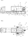
FIG 3 is a side view of a lift truck of the present invention, in which the lift truck is in the process of lifting/placing a load out of/into a shipping container on a transport vehicle; and -
FIG 4 is a top view of a lift truck of the present invention, in which the lift truck of the present invention is in the process of lifting/placing a load out of/into a shipping container on a transport vehicle, and in which the arms of the chassis can be seen to straddle the width of the shipping container. - With reference to
Figure 3 , a lift truck (10) of the invention comprises a chassis (12) and a lifting mechanism (14), the chassis comprising left and right front ground wheels (20L, 20R, respectively) and a single rear ground wheel (22) disposed centrally between, but rearwardly displaced, relative to the front ground wheels. In some embodiments, the chassis (12) may comprise more than one rear ground wheel (22). For example, the chassis (12) may comprise left and right rear ground wheels which may be substantially aligned with, and/or rearwardly displaced from, the left and right front ground wheels (20L, 20R), respectively. The chassis (12) further comprises two spaced-apart left and right arms (16L, 16R, respectively) to each of which a respective one of said front ground wheels (20L, 20R) is respectively mounted, and wherein the arms (16L, 16R) are sufficiently spaced-apart to allow, in use, the arms of the chassis to straddle a width of a shipping container (C). As illustrated inFigure 4 , the arms (16L, 16R) of the chassis may be spaced-apart and disposed substantially parallel to each other. - The front ground wheels (20L, 20R) act as the fulcrum point (F) when the lift truck (10) is used to lift/place a load. In use, the front ground wheels (20L, 20R) of the lift truck (10) of the invention can be positioned closer to the load to be lifted/placed since the arms (16L, 16R) are sufficiently spaced apart to allow the arms to straddle the width of a shipping container containing the load (see
Figures 3 and 4 ). As a result of this configuration, the distance from the load to the fulcrum point (F), designated L5 inFigure 3 , is reduced for the lift truck (10) of the present invention. Based on the principle of the lever, (W5 x L5) must be less than (W6 x L6). (W5 = weight of the load; L5 = distance from the COG of the load to the fulcrum point (F); W6 = weight of the lift truck; L6 = distance from the COG of the lift truck to fulcrum point (F).) Since W6 and L6 are fixed, the weight of the load to be lifted (W5) may be greater as a result of the shortening of the L5 distance. Consequently, the lift truck (10) of the present invention can lift relatively heavier loads than conventional lift trucks of a similar size but without the innovative design of the present lift truck (10). - As illustrated in
Figure 3 , the front ground wheels (20L, 20R) may be respectively mounted adjacent a first end of the spaced-apart arms (16L, 16R). The chassis may also comprise a transverse portion (18) arranged perpendicular to the two spaced-apart arms (16L, 16R). In a plan view of the lift truck of the invention (Figure 4 ), the chassis (12) may be seen to be substantially U-shaped comprising the transverse portion (18) arranged perpendicular to the two spaced-apart arms (16L, 16R), wherein the transverse portion (18) is connected at the second end of each arm (16L, 16R) opposing the first ends to which the front ground wheels (20L, 20R) are mounted. - The rear ground wheel (22) may be mounted to the transverse portion (18) of the chassis (12), and thus may be rearwardly displaced relative to the front ground wheels (20L, 20R). The rear ground wheel (22) may be a driven wheel and/or may be steerable by an operator (O). In embodiments of the invention, the front ground wheels (20L, 20R) may alternatively, or additionally, be driven wheels and/or may be steerable by the operator (O). In other embodiments, the lift truck (10) may comprise more than one rear ground wheel (22) which may be driven and/or steerable, and which may be mounted to the transverse portion (18) of the chassis (12), or to the arms (16L, 16R), rearwardly of the front ground wheels (20L, 20R). The lift truck (10) may further comprise means to control and/or synchronise the rotation and direction of each wheel (not shown).
- As depicted in
Figure 3 , the lift truck (10) of the invention also comprises a lifting mechanism (14) attached to the chassis (12), optionally to the transverse portion (18) of the chassis (12). Advantageously, the lifting mechanism (14) is attached to the chassis (12) rearwardly of the front ground wheels (20L, 20R), thus contributing to moving the COG of the lift truck (10) away from the fulcrum point (P). In some embodiments, the lifting mechanism (14) is attached to the chassis rearwardly of the front ground wheels (20L, 20R). The lifting mechanism (14) may comprise a conventional lifting mast and lift forks. Advantageously, the lifting mechanism (14) comprises a boom (24), which may further comprise a set of lift forks (26), as depicted inFigure 3 . The boom (24) is particularly useful to allow the lift truck (10) to reach into a shipping container (C) to lift/place a load at the far end of the container, i.e. the end of the container distal to the opening. In this regard, the boom (24) may be extendable and/or retractable so that when the lift truck (10) is positioned at the opening of a shipping container (C), the boom (24) may be extended/retracted to lift/place a load at the far end of the container. In some embodiments of the invention, the boom (24) may be telescopic. - The lift truck (10) may also comprise elevating means for raising and lowering the boom (24) relative to the chassis (12) and/or relative to the ground on which the lift truck (10) is positioned. Suitable elevating means include a ram (28), such as a hydraulic ram. The ram (28) may be located between the chassis (12) and the boom (24). Operation of the ram (28) may cause the boom (24) to by raised/lowered relative to the chassis (12). Alternatively, or additionally, the lift truck (10) may comprise pushing means (not shown) for extending and/or retracting the extendable/retractable boom (24). Suitable pushing means include a ram, such as a hydraulic ram.
- The lift truck (10) of the invention may further comprise a cab (30), that is, an operator's cabin, located on the chassis (12). An operator (O) may control the operation of the lift truck (10) from the cab (30), including the operation of the driven wheel(s) and the lifting mechanism (14). As depicted in
Figure 3 , the cab (30) may be located on the transverse portion (18) of the chassis (12) proximate to an end of the transverse portion. In other words, the cab (30) may be located to one side of the chassis (12). Advantageously, this arrangement allows the operator's field of vision (V) to simultaneously include the interior of an open shipping container (C) and the exterior of the shipping container (C) when the operator (O) is operating the lift truck (10) to lift/place a load out of/into the shipping container (C). This allows for safer and more accurate control of the lift truck (10) and the loading/unloading process. It will further be appreciated that a container (C) can be off-loaded while being on a transport vehicle or positioned at ground level. In a further modification of the lift truck (10), the operator's cab (30) may be removed and the lift truck (10) controlled remotely. - As will be understood from the present description, the arms (16L, 16R) of the chassis (12) are sufficiently spaced apart to straddle a width of a standard shipping container (C). Conventional standard shipping containers include 20, 30, 40 or 45 foot containers. The width of shipping containers may vary and so the distance between the arms (16L, 16R) of the chassis (12) may depend on the width of the container (C) in respect of which the lift truck (10) of the invention is to be used. Therefore, the distance between the arms (16L, 16R) may be at least 1.5 m, 1.75 m, 2 m, 2.25 m, 2.5 m, 2.75 m, 3 m or more. The width of commonly used shipping containers is typically 2.44 m (i.e. 8 feet). Therefore, the arms (16L, 16R) of the chassis (12) may be sufficiently spaced apart to straddle a container width of 2.438 m. In some embodiments, the arms (16L, 16R) of the chassis (12) may sufficiently spaced apart to allow for clearance at either side of a container (C) when the arms (16L, 16R) of the chassis (12) are positioned to straddle the width of the container. Such clearance may be necessary to allow the arms (16L, 16R) to straddle a container located on a transport vehicle, i.e. to straddle the container and the transport vehicle, and to take account of the transport vehicle having a greater width than the container. For example, the chassis of the transport vehicle, or features or appendages of the transport vehicle, e.g. side marking lights, may protrude past the width of the container when positioned on the transport vehicle. Therefore, the arms (16L, 16R) of the chassis (12) may be spaced apart such that the distance between the arms is at least 2.5 m, optionally at least 2.8 m, optionally at least 3 m, or more.
- The advantages of the lift truck (10) described above include:
- 1. The lift truck (10) can be lighter than conventional lift trucks for a particular load weight that is required to be lifted.
- 2. The lift truck (10) is more compact and manoeuvrable than conventional lift trucks as a result of it being smaller and lighter.
- 3. The ground pressure at the fulcrum point is lower for the lift truck (10) of the invention.
- 4. The lift truck (10) is more economical to manufacture than conventional lift trucks due its lighter weight.
- 5. The lift truck (10) has lower fuel consumption than conventional lift trucks due to the overall construction being lighter and, as a consequence, a smaller power unit may be used.
- 6. The lift truck (10) can off-load / load a container while the container is on a transport vehicle.
- 7. Loading docks/bays are not required by the lift truck (10) to off-load / load a container.
- The invention is not limited to the embodiment described herein but can be amended or modified without departing from the scope of the present invention as defined by the appended claims.
Claims (15)
- A lift truck (10) comprising a chassis (12) and a lifting mechanism (14) mounted on the chassis, the chassis comprising first and second front ground wheels (20L, 20R) and at least one rear ground wheel (22), the chassis further comprising first and second spaced-apart arms (16L, 16R) with the first front ground wheel being mounted on the first arm and the second ground wheel mounted on the second arm, and wherein the arms are sufficiently spaced apart to allow, in use, the arms of the chassis to straddle a width of a shipping container (C), characterised in that the chassis further comprises a cab (30) from which an operator (O) can control the lift truck (10) and in use, the operator's field of vision simultaneously includes the interior of an open shipping container (C) and the exterior of the shipping container (C) when the arms of the chassis (12) straddle the width of the container (C).
- The lift truck (10) of Claim 1, wherein the arms (20L, 20R) of the chassis (12) are spaced apart and substantially parallel to each other.
- The lift truck (10) of Claim 1 or 2, wherein, in use, the arms (20L, 20R) of the chassis (12) are substantially parallel to the ground.
- The lift truck of (10) any one of Claims 1 to 3, wherein each arm of the chassis (12) has first and second opposing ends, and wherein the front ground wheels (16L, 16R) are respectively mounted at or adjacent the first end of each spaced-apart arm (20L, 20R).
- The lift truck (10) of any one of Claims 1 to 4, wherein the chassis (12) comprises a transverse portion (18) arranged perpendicular to the two spaced-apart arms (20L, 20R).
- The lift truck (10) of Claim 5, wherein the transverse portion (18) is connected to the arms proximate to the second end of each spaced-apart arm.
- The lift truck (10) of claim 5 or 6, wherein the at least one rear ground wheel (22) is mounted to the transverse portion of the chassis.
- The lift truck (10) of any one of the preceding claims, wherein the at least one rear ground wheel (22) is a driven wheel, optionally, a driven, steerable wheel, optionally wherein the two front ground wheels (16L, 16R) are driven wheels, optionally, driven, steerable wheels.
- The lift truck (10) of any one of Claims 5 to 8, wherein the lifting mechanism is attached to the transverse portion (18) of the chassis (12).
- The lift truck (10) of any one of the preceding claims, wherein the lifting mechanism is attached to the chassis (12) rearwardly of the front ground wheels (16L, 16R).
- The lift truck (10) of any one of the preceding claims, wherein the lifting mechanism comprises a conventional lifting mast and one or more lift forks.
- The lift truck (10) of any one of the preceding claims, wherein the lifting mechanism comprises a boom (24).
- The lift truck (10) of Claim 12, wherein the boom (24) further comprises means for engaging a load.
- The lift truck (10) of Claim 13, wherein lift truck further comprises elevating means for raising and lowering the boom relative to the chassis (12).
- The lift truck (10) of Claim 1, wherein the cab is located on the transverse portion of the chassis, optionally wherein the cab (30) is located proximate to an end of the transverse portion (18), optionally, proximate to an end of the transverse portion (18) at or adjacent the second end of an arm of the chassis (12).
Applications Claiming Priority (1)
| Application Number | Priority Date | Filing Date | Title |
|---|---|---|---|
| PCT/EP2014/061750 WO2015185146A1 (en) | 2014-06-05 | 2014-06-05 | Container loader / unloader |
Publications (2)
| Publication Number | Publication Date |
|---|---|
| EP3152149A1 EP3152149A1 (en) | 2017-04-12 |
| EP3152149B1 true EP3152149B1 (en) | 2018-11-28 |
Family
ID=50942674
Family Applications (1)
| Application Number | Title | Priority Date | Filing Date |
|---|---|---|---|
| EP14730122.0A Active EP3152149B1 (en) | 2014-06-05 | 2014-06-05 | Container loader / unloader |
Country Status (2)
| Country | Link |
|---|---|
| EP (1) | EP3152149B1 (en) |
| WO (1) | WO2015185146A1 (en) |
Family Cites Families (3)
| Publication number | Priority date | Publication date | Assignee | Title |
|---|---|---|---|---|
| DE4427901C2 (en) * | 1994-08-06 | 1996-06-05 | Kaup Gmbh & Co Kg | Device for loading containers |
| EP0701963B2 (en) * | 1994-09-14 | 2004-08-18 | Manitou Bf | Motorised lift truck with telescopic arm |
| EP2155533A4 (en) * | 2007-05-07 | 2013-01-30 | Princeton Delivery Systems Inc | Four-way forklift with outwardly pivoting wheel arms |
-
2014
- 2014-06-05 EP EP14730122.0A patent/EP3152149B1/en active Active
- 2014-06-05 WO PCT/EP2014/061750 patent/WO2015185146A1/en active Application Filing
Non-Patent Citations (1)
| Title |
|---|
| None * |
Also Published As
| Publication number | Publication date |
|---|---|
| EP3152149A1 (en) | 2017-04-12 |
| WO2015185146A1 (en) | 2015-12-10 |
Similar Documents
| Publication | Publication Date | Title |
|---|---|---|
| EP1871641B1 (en) | Apparatus for lifting, handling and transporting a container | |
| US8528700B2 (en) | Industrial truck with a lifting device and a towing device | |
| US9248774B2 (en) | System for adjusting over-axle weight of a vacuum tank truck | |
| EP1792869B1 (en) | A forklift loading support | |
| EP2045207B1 (en) | Load controlled stabilizer system | |
| JP2007169062A (en) | Improved straddle carrier | |
| US7428940B2 (en) | Steerable transport trolley | |
| US10131264B2 (en) | Hooklift trailer | |
| CN103601107A (en) | Forklift with liftable driving cab | |
| EP3114073B1 (en) | Equipment attaching device for vehicles | |
| EP3521236B1 (en) | Material handling vehicle | |
| EP3152149B1 (en) | Container loader / unloader | |
| US4390314A (en) | Container truck for lifting and carrying away a container | |
| AU2006319069B2 (en) | Tool for handling of loads | |
| CN202784914U (en) | Rolling-over type unloading machine | |
| EP3835239B1 (en) | Material handling equipment | |
| US11459193B1 (en) | Material handling equipment | |
| US3669290A (en) | Container handling vehicle | |
| US10221049B1 (en) | Lift attachment apparatus | |
| JP2005096967A (en) | Reach stacker | |
| CN102815644A (en) | Extension-type straddle device of lorry-mounted cargo loading and unloading operation device | |
| EP2377806B1 (en) | Forklift truck | |
| SE539034C2 (en) | Hoist | |
| EP3362402B1 (en) | A truck mounted forklift | |
| EP2634042A1 (en) | End-dump discharging device for a receptable |
Legal Events
| Date | Code | Title | Description |
|---|---|---|---|
| STAA | Information on the status of an ep patent application or granted ep patent |
Free format text: STATUS: THE INTERNATIONAL PUBLICATION HAS BEEN MADE |
|
| PUAI | Public reference made under article 153(3) epc to a published international application that has entered the european phase |
Free format text: ORIGINAL CODE: 0009012 |
|
| STAA | Information on the status of an ep patent application or granted ep patent |
Free format text: STATUS: REQUEST FOR EXAMINATION WAS MADE |
|
| 17P | Request for examination filed |
Effective date: 20161223 |
|
| AK | Designated contracting states |
Kind code of ref document: A1 Designated state(s): AL AT BE BG CH CY CZ DE DK EE ES FI FR GB GR HR HU IE IS IT LI LT LU LV MC MK MT NL NO PL PT RO RS SE SI SK SM TR |
|
| AX | Request for extension of the european patent |
Extension state: BA ME |
|
| DAX | Request for extension of the european patent (deleted) | ||
| GRAP | Despatch of communication of intention to grant a patent |
Free format text: ORIGINAL CODE: EPIDOSNIGR1 |
|
| STAA | Information on the status of an ep patent application or granted ep patent |
Free format text: STATUS: GRANT OF PATENT IS INTENDED |
|
| INTG | Intention to grant announced |
Effective date: 20180620 |
|
| GRAS | Grant fee paid |
Free format text: ORIGINAL CODE: EPIDOSNIGR3 |
|
| GRAA | (expected) grant |
Free format text: ORIGINAL CODE: 0009210 |
|
| STAA | Information on the status of an ep patent application or granted ep patent |
Free format text: STATUS: THE PATENT HAS BEEN GRANTED |
|
| AK | Designated contracting states |
Kind code of ref document: B1 Designated state(s): AL AT BE BG CH CY CZ DE DK EE ES FI FR GB GR HR HU IE IS IT LI LT LU LV MC MK MT NL NO PL PT RO RS SE SI SK SM TR |
|
| REG | Reference to a national code |
Ref country code: CH Ref legal event code: EP |
|
| REG | Reference to a national code |
Ref country code: AT Ref legal event code: REF Ref document number: 1070001 Country of ref document: AT Kind code of ref document: T Effective date: 20181215 |
|
| REG | Reference to a national code |
Ref country code: DE Ref legal event code: R096 Ref document number: 602014036917 Country of ref document: DE |
|
| REG | Reference to a national code |
Ref country code: IE Ref legal event code: FG4D |
|
| REG | Reference to a national code |
Ref country code: NL Ref legal event code: MP Effective date: 20181128 |
|
| REG | Reference to a national code |
Ref country code: LT Ref legal event code: MG4D |
|
| REG | Reference to a national code |
Ref country code: AT Ref legal event code: MK05 Ref document number: 1070001 Country of ref document: AT Kind code of ref document: T Effective date: 20181128 |
|
| PG25 | Lapsed in a contracting state [announced via postgrant information from national office to epo] |
Ref country code: NO Free format text: LAPSE BECAUSE OF FAILURE TO SUBMIT A TRANSLATION OF THE DESCRIPTION OR TO PAY THE FEE WITHIN THE PRESCRIBED TIME-LIMIT Effective date: 20190228 Ref country code: BG Free format text: LAPSE BECAUSE OF FAILURE TO SUBMIT A TRANSLATION OF THE DESCRIPTION OR TO PAY THE FEE WITHIN THE PRESCRIBED TIME-LIMIT Effective date: 20190228 Ref country code: IS Free format text: LAPSE BECAUSE OF FAILURE TO SUBMIT A TRANSLATION OF THE DESCRIPTION OR TO PAY THE FEE WITHIN THE PRESCRIBED TIME-LIMIT Effective date: 20190328 Ref country code: FI Free format text: LAPSE BECAUSE OF FAILURE TO SUBMIT A TRANSLATION OF THE DESCRIPTION OR TO PAY THE FEE WITHIN THE PRESCRIBED TIME-LIMIT Effective date: 20181128 Ref country code: LT Free format text: LAPSE BECAUSE OF FAILURE TO SUBMIT A TRANSLATION OF THE DESCRIPTION OR TO PAY THE FEE WITHIN THE PRESCRIBED TIME-LIMIT Effective date: 20181128 Ref country code: LV Free format text: LAPSE BECAUSE OF FAILURE TO SUBMIT A TRANSLATION OF THE DESCRIPTION OR TO PAY THE FEE WITHIN THE PRESCRIBED TIME-LIMIT Effective date: 20181128 Ref country code: HR Free format text: LAPSE BECAUSE OF FAILURE TO SUBMIT A TRANSLATION OF THE DESCRIPTION OR TO PAY THE FEE WITHIN THE PRESCRIBED TIME-LIMIT Effective date: 20181128 Ref country code: ES Free format text: LAPSE BECAUSE OF FAILURE TO SUBMIT A TRANSLATION OF THE DESCRIPTION OR TO PAY THE FEE WITHIN THE PRESCRIBED TIME-LIMIT Effective date: 20181128 Ref country code: AT Free format text: LAPSE BECAUSE OF FAILURE TO SUBMIT A TRANSLATION OF THE DESCRIPTION OR TO PAY THE FEE WITHIN THE PRESCRIBED TIME-LIMIT Effective date: 20181128 |
|
| PG25 | Lapsed in a contracting state [announced via postgrant information from national office to epo] |
Ref country code: GR Free format text: LAPSE BECAUSE OF FAILURE TO SUBMIT A TRANSLATION OF THE DESCRIPTION OR TO PAY THE FEE WITHIN THE PRESCRIBED TIME-LIMIT Effective date: 20190301 Ref country code: PT Free format text: LAPSE BECAUSE OF FAILURE TO SUBMIT A TRANSLATION OF THE DESCRIPTION OR TO PAY THE FEE WITHIN THE PRESCRIBED TIME-LIMIT Effective date: 20190328 Ref country code: SE Free format text: LAPSE BECAUSE OF FAILURE TO SUBMIT A TRANSLATION OF THE DESCRIPTION OR TO PAY THE FEE WITHIN THE PRESCRIBED TIME-LIMIT Effective date: 20181128 Ref country code: RS Free format text: LAPSE BECAUSE OF FAILURE TO SUBMIT A TRANSLATION OF THE DESCRIPTION OR TO PAY THE FEE WITHIN THE PRESCRIBED TIME-LIMIT Effective date: 20181128 Ref country code: AL Free format text: LAPSE BECAUSE OF FAILURE TO SUBMIT A TRANSLATION OF THE DESCRIPTION OR TO PAY THE FEE WITHIN THE PRESCRIBED TIME-LIMIT Effective date: 20181128 |
|
| PG25 | Lapsed in a contracting state [announced via postgrant information from national office to epo] |
Ref country code: NL Free format text: LAPSE BECAUSE OF FAILURE TO SUBMIT A TRANSLATION OF THE DESCRIPTION OR TO PAY THE FEE WITHIN THE PRESCRIBED TIME-LIMIT Effective date: 20181128 |
|
| PG25 | Lapsed in a contracting state [announced via postgrant information from national office to epo] |
Ref country code: DK Free format text: LAPSE BECAUSE OF FAILURE TO SUBMIT A TRANSLATION OF THE DESCRIPTION OR TO PAY THE FEE WITHIN THE PRESCRIBED TIME-LIMIT Effective date: 20181128 Ref country code: CZ Free format text: LAPSE BECAUSE OF FAILURE TO SUBMIT A TRANSLATION OF THE DESCRIPTION OR TO PAY THE FEE WITHIN THE PRESCRIBED TIME-LIMIT Effective date: 20181128 Ref country code: PL Free format text: LAPSE BECAUSE OF FAILURE TO SUBMIT A TRANSLATION OF THE DESCRIPTION OR TO PAY THE FEE WITHIN THE PRESCRIBED TIME-LIMIT Effective date: 20181128 |
|
| REG | Reference to a national code |
Ref country code: DE Ref legal event code: R097 Ref document number: 602014036917 Country of ref document: DE |
|
| PG25 | Lapsed in a contracting state [announced via postgrant information from national office to epo] |
Ref country code: SK Free format text: LAPSE BECAUSE OF FAILURE TO SUBMIT A TRANSLATION OF THE DESCRIPTION OR TO PAY THE FEE WITHIN THE PRESCRIBED TIME-LIMIT Effective date: 20181128 Ref country code: EE Free format text: LAPSE BECAUSE OF FAILURE TO SUBMIT A TRANSLATION OF THE DESCRIPTION OR TO PAY THE FEE WITHIN THE PRESCRIBED TIME-LIMIT Effective date: 20181128 Ref country code: RO Free format text: LAPSE BECAUSE OF FAILURE TO SUBMIT A TRANSLATION OF THE DESCRIPTION OR TO PAY THE FEE WITHIN THE PRESCRIBED TIME-LIMIT Effective date: 20181128 Ref country code: SM Free format text: LAPSE BECAUSE OF FAILURE TO SUBMIT A TRANSLATION OF THE DESCRIPTION OR TO PAY THE FEE WITHIN THE PRESCRIBED TIME-LIMIT Effective date: 20181128 |
|
| PLBE | No opposition filed within time limit |
Free format text: ORIGINAL CODE: 0009261 |
|
| STAA | Information on the status of an ep patent application or granted ep patent |
Free format text: STATUS: NO OPPOSITION FILED WITHIN TIME LIMIT |
|
| PG25 | Lapsed in a contracting state [announced via postgrant information from national office to epo] |
Ref country code: SI Free format text: LAPSE BECAUSE OF FAILURE TO SUBMIT A TRANSLATION OF THE DESCRIPTION OR TO PAY THE FEE WITHIN THE PRESCRIBED TIME-LIMIT Effective date: 20181128 |
|
| 26N | No opposition filed |
Effective date: 20190829 |
|
| PG25 | Lapsed in a contracting state [announced via postgrant information from national office to epo] |
Ref country code: MC Free format text: LAPSE BECAUSE OF FAILURE TO SUBMIT A TRANSLATION OF THE DESCRIPTION OR TO PAY THE FEE WITHIN THE PRESCRIBED TIME-LIMIT Effective date: 20181128 |
|
| REG | Reference to a national code |
Ref country code: CH Ref legal event code: PL |
|
| GBPC | Gb: european patent ceased through non-payment of renewal fee |
Effective date: 20190605 |
|
| REG | Reference to a national code |
Ref country code: BE Ref legal event code: MM Effective date: 20190630 |
|
| PG25 | Lapsed in a contracting state [announced via postgrant information from national office to epo] |
Ref country code: TR Free format text: LAPSE BECAUSE OF FAILURE TO SUBMIT A TRANSLATION OF THE DESCRIPTION OR TO PAY THE FEE WITHIN THE PRESCRIBED TIME-LIMIT Effective date: 20181128 |
|
| PG25 | Lapsed in a contracting state [announced via postgrant information from national office to epo] |
Ref country code: IE Free format text: LAPSE BECAUSE OF NON-PAYMENT OF DUE FEES Effective date: 20190605 Ref country code: GB Free format text: LAPSE BECAUSE OF NON-PAYMENT OF DUE FEES Effective date: 20190605 |
|
| PG25 | Lapsed in a contracting state [announced via postgrant information from national office to epo] |
Ref country code: LU Free format text: LAPSE BECAUSE OF NON-PAYMENT OF DUE FEES Effective date: 20190605 Ref country code: BE Free format text: LAPSE BECAUSE OF NON-PAYMENT OF DUE FEES Effective date: 20190630 Ref country code: CH Free format text: LAPSE BECAUSE OF NON-PAYMENT OF DUE FEES Effective date: 20190630 Ref country code: LI Free format text: LAPSE BECAUSE OF NON-PAYMENT OF DUE FEES Effective date: 20190630 |
|
| PG25 | Lapsed in a contracting state [announced via postgrant information from national office to epo] |
Ref country code: FR Free format text: LAPSE BECAUSE OF NON-PAYMENT OF DUE FEES Effective date: 20190630 |
|
| PG25 | Lapsed in a contracting state [announced via postgrant information from national office to epo] |
Ref country code: CY Free format text: LAPSE BECAUSE OF FAILURE TO SUBMIT A TRANSLATION OF THE DESCRIPTION OR TO PAY THE FEE WITHIN THE PRESCRIBED TIME-LIMIT Effective date: 20181128 |
|
| PG25 | Lapsed in a contracting state [announced via postgrant information from national office to epo] |
Ref country code: HU Free format text: LAPSE BECAUSE OF FAILURE TO SUBMIT A TRANSLATION OF THE DESCRIPTION OR TO PAY THE FEE WITHIN THE PRESCRIBED TIME-LIMIT; INVALID AB INITIO Effective date: 20140605 Ref country code: MT Free format text: LAPSE BECAUSE OF FAILURE TO SUBMIT A TRANSLATION OF THE DESCRIPTION OR TO PAY THE FEE WITHIN THE PRESCRIBED TIME-LIMIT Effective date: 20181128 |
|
| PG25 | Lapsed in a contracting state [announced via postgrant information from national office to epo] |
Ref country code: MK Free format text: LAPSE BECAUSE OF FAILURE TO SUBMIT A TRANSLATION OF THE DESCRIPTION OR TO PAY THE FEE WITHIN THE PRESCRIBED TIME-LIMIT Effective date: 20181128 |
|
| PGFP | Annual fee paid to national office [announced via postgrant information from national office to epo] |
Ref country code: DE Payment date: 20240617 Year of fee payment: 11 |
|
| PGFP | Annual fee paid to national office [announced via postgrant information from national office to epo] |
Ref country code: IT Payment date: 20240628 Year of fee payment: 11 |