EP3151880B1 - Logging device for drug delivery device - Google Patents
Logging device for drug delivery device Download PDFInfo
- Publication number
- EP3151880B1 EP3151880B1 EP15726194.2A EP15726194A EP3151880B1 EP 3151880 B1 EP3151880 B1 EP 3151880B1 EP 15726194 A EP15726194 A EP 15726194A EP 3151880 B1 EP3151880 B1 EP 3151880B1
- Authority
- EP
- European Patent Office
- Prior art keywords
- drug
- dose
- turned
- drug delivery
- amount
- Prior art date
- Legal status (The legal status is an assumption and is not a legal conclusion. Google has not performed a legal analysis and makes no representation as to the accuracy of the status listed.)
- Active
Links
Images


Classifications
-
- G—PHYSICS
- G16—INFORMATION AND COMMUNICATION TECHNOLOGY [ICT] SPECIALLY ADAPTED FOR SPECIFIC APPLICATION FIELDS
- G16H—HEALTHCARE INFORMATICS, i.e. INFORMATION AND COMMUNICATION TECHNOLOGY [ICT] SPECIALLY ADAPTED FOR THE HANDLING OR PROCESSING OF MEDICAL OR HEALTHCARE DATA
- G16H20/00—ICT specially adapted for therapies or health-improving plans, e.g. for handling prescriptions, for steering therapy or for monitoring patient compliance
- G16H20/10—ICT specially adapted for therapies or health-improving plans, e.g. for handling prescriptions, for steering therapy or for monitoring patient compliance relating to drugs or medications, e.g. for ensuring correct administration to patients
- G16H20/13—ICT specially adapted for therapies or health-improving plans, e.g. for handling prescriptions, for steering therapy or for monitoring patient compliance relating to drugs or medications, e.g. for ensuring correct administration to patients delivered from dispensers
-
- A—HUMAN NECESSITIES
- A61—MEDICAL OR VETERINARY SCIENCE; HYGIENE
- A61M—DEVICES FOR INTRODUCING MEDIA INTO, OR ONTO, THE BODY; DEVICES FOR TRANSDUCING BODY MEDIA OR FOR TAKING MEDIA FROM THE BODY; DEVICES FOR PRODUCING OR ENDING SLEEP OR STUPOR
- A61M5/00—Devices for bringing media into the body in a subcutaneous, intra-vascular or intramuscular way; Accessories therefor, e.g. filling or cleaning devices, arm-rests
- A61M5/178—Syringes
- A61M5/20—Automatic syringes, e.g. with automatically actuated piston rod, with automatic needle injection, filling automatically
-
- A—HUMAN NECESSITIES
- A61—MEDICAL OR VETERINARY SCIENCE; HYGIENE
- A61M—DEVICES FOR INTRODUCING MEDIA INTO, OR ONTO, THE BODY; DEVICES FOR TRANSDUCING BODY MEDIA OR FOR TAKING MEDIA FROM THE BODY; DEVICES FOR PRODUCING OR ENDING SLEEP OR STUPOR
- A61M5/00—Devices for bringing media into the body in a subcutaneous, intra-vascular or intramuscular way; Accessories therefor, e.g. filling or cleaning devices, arm-rests
- A61M5/178—Syringes
- A61M5/24—Ampoule syringes, i.e. syringes with needle for use in combination with replaceable ampoules or carpules, e.g. automatic
-
- A—HUMAN NECESSITIES
- A61—MEDICAL OR VETERINARY SCIENCE; HYGIENE
- A61M—DEVICES FOR INTRODUCING MEDIA INTO, OR ONTO, THE BODY; DEVICES FOR TRANSDUCING BODY MEDIA OR FOR TAKING MEDIA FROM THE BODY; DEVICES FOR PRODUCING OR ENDING SLEEP OR STUPOR
- A61M5/00—Devices for bringing media into the body in a subcutaneous, intra-vascular or intramuscular way; Accessories therefor, e.g. filling or cleaning devices, arm-rests
- A61M5/178—Syringes
- A61M5/31—Details
- A61M5/315—Pistons; Piston-rods; Guiding, blocking or restricting the movement of the rod or piston; Appliances on the rod for facilitating dosing ; Dosing mechanisms
- A61M5/31533—Dosing mechanisms, i.e. setting a dose
- A61M5/31545—Setting modes for dosing
- A61M5/31546—Electrically operated dose setting, e.g. input via touch screen or plus/minus buttons
-
- A—HUMAN NECESSITIES
- A61—MEDICAL OR VETERINARY SCIENCE; HYGIENE
- A61M—DEVICES FOR INTRODUCING MEDIA INTO, OR ONTO, THE BODY; DEVICES FOR TRANSDUCING BODY MEDIA OR FOR TAKING MEDIA FROM THE BODY; DEVICES FOR PRODUCING OR ENDING SLEEP OR STUPOR
- A61M5/00—Devices for bringing media into the body in a subcutaneous, intra-vascular or intramuscular way; Accessories therefor, e.g. filling or cleaning devices, arm-rests
- A61M5/178—Syringes
- A61M5/31—Details
- A61M5/315—Pistons; Piston-rods; Guiding, blocking or restricting the movement of the rod or piston; Appliances on the rod for facilitating dosing ; Dosing mechanisms
- A61M5/31565—Administration mechanisms, i.e. constructional features, modes of administering a dose
-
- A—HUMAN NECESSITIES
- A61—MEDICAL OR VETERINARY SCIENCE; HYGIENE
- A61M—DEVICES FOR INTRODUCING MEDIA INTO, OR ONTO, THE BODY; DEVICES FOR TRANSDUCING BODY MEDIA OR FOR TAKING MEDIA FROM THE BODY; DEVICES FOR PRODUCING OR ENDING SLEEP OR STUPOR
- A61M5/00—Devices for bringing media into the body in a subcutaneous, intra-vascular or intramuscular way; Accessories therefor, e.g. filling or cleaning devices, arm-rests
- A61M5/178—Syringes
- A61M5/31—Details
- A61M5/32—Needles; Details of needles pertaining to their connection with syringe or hub; Accessories for bringing the needle into, or holding the needle on, the body; Devices for protection of needles
- A61M5/3202—Devices for protection of the needle before use, e.g. caps
-
- G—PHYSICS
- G16—INFORMATION AND COMMUNICATION TECHNOLOGY [ICT] SPECIALLY ADAPTED FOR SPECIFIC APPLICATION FIELDS
- G16H—HEALTHCARE INFORMATICS, i.e. INFORMATION AND COMMUNICATION TECHNOLOGY [ICT] SPECIALLY ADAPTED FOR THE HANDLING OR PROCESSING OF MEDICAL OR HEALTHCARE DATA
- G16H20/00—ICT specially adapted for therapies or health-improving plans, e.g. for handling prescriptions, for steering therapy or for monitoring patient compliance
- G16H20/10—ICT specially adapted for therapies or health-improving plans, e.g. for handling prescriptions, for steering therapy or for monitoring patient compliance relating to drugs or medications, e.g. for ensuring correct administration to patients
- G16H20/17—ICT specially adapted for therapies or health-improving plans, e.g. for handling prescriptions, for steering therapy or for monitoring patient compliance relating to drugs or medications, e.g. for ensuring correct administration to patients delivered via infusion or injection
-
- G—PHYSICS
- G16—INFORMATION AND COMMUNICATION TECHNOLOGY [ICT] SPECIALLY ADAPTED FOR SPECIFIC APPLICATION FIELDS
- G16H—HEALTHCARE INFORMATICS, i.e. INFORMATION AND COMMUNICATION TECHNOLOGY [ICT] SPECIALLY ADAPTED FOR THE HANDLING OR PROCESSING OF MEDICAL OR HEALTHCARE DATA
- G16H40/00—ICT specially adapted for the management or administration of healthcare resources or facilities; ICT specially adapted for the management or operation of medical equipment or devices
- G16H40/60—ICT specially adapted for the management or administration of healthcare resources or facilities; ICT specially adapted for the management or operation of medical equipment or devices for the operation of medical equipment or devices
- G16H40/63—ICT specially adapted for the management or administration of healthcare resources or facilities; ICT specially adapted for the management or operation of medical equipment or devices for the operation of medical equipment or devices for local operation
-
- G—PHYSICS
- G16—INFORMATION AND COMMUNICATION TECHNOLOGY [ICT] SPECIALLY ADAPTED FOR SPECIFIC APPLICATION FIELDS
- G16Z—INFORMATION AND COMMUNICATION TECHNOLOGY [ICT] SPECIALLY ADAPTED FOR SPECIFIC APPLICATION FIELDS, NOT OTHERWISE PROVIDED FOR
- G16Z99/00—Subject matter not provided for in other main groups of this subclass
-
- A—HUMAN NECESSITIES
- A61—MEDICAL OR VETERINARY SCIENCE; HYGIENE
- A61M—DEVICES FOR INTRODUCING MEDIA INTO, OR ONTO, THE BODY; DEVICES FOR TRANSDUCING BODY MEDIA OR FOR TAKING MEDIA FROM THE BODY; DEVICES FOR PRODUCING OR ENDING SLEEP OR STUPOR
- A61M5/00—Devices for bringing media into the body in a subcutaneous, intra-vascular or intramuscular way; Accessories therefor, e.g. filling or cleaning devices, arm-rests
- A61M5/178—Syringes
- A61M5/24—Ampoule syringes, i.e. syringes with needle for use in combination with replaceable ampoules or carpules, e.g. automatic
- A61M2005/2403—Ampoule inserted into the ampoule holder
- A61M2005/2407—Ampoule inserted into the ampoule holder from the rear
-
- A—HUMAN NECESSITIES
- A61—MEDICAL OR VETERINARY SCIENCE; HYGIENE
- A61M—DEVICES FOR INTRODUCING MEDIA INTO, OR ONTO, THE BODY; DEVICES FOR TRANSDUCING BODY MEDIA OR FOR TAKING MEDIA FROM THE BODY; DEVICES FOR PRODUCING OR ENDING SLEEP OR STUPOR
- A61M5/00—Devices for bringing media into the body in a subcutaneous, intra-vascular or intramuscular way; Accessories therefor, e.g. filling or cleaning devices, arm-rests
- A61M5/178—Syringes
- A61M5/31—Details
- A61M2005/3125—Details specific display means, e.g. to indicate dose setting
- A61M2005/3126—Specific display means related to dosing
-
- A—HUMAN NECESSITIES
- A61—MEDICAL OR VETERINARY SCIENCE; HYGIENE
- A61M—DEVICES FOR INTRODUCING MEDIA INTO, OR ONTO, THE BODY; DEVICES FOR TRANSDUCING BODY MEDIA OR FOR TAKING MEDIA FROM THE BODY; DEVICES FOR PRODUCING OR ENDING SLEEP OR STUPOR
- A61M2205/00—General characteristics of the apparatus
- A61M2205/14—Detection of the presence or absence of a tube, a connector or a container in an apparatus
-
- A—HUMAN NECESSITIES
- A61—MEDICAL OR VETERINARY SCIENCE; HYGIENE
- A61M—DEVICES FOR INTRODUCING MEDIA INTO, OR ONTO, THE BODY; DEVICES FOR TRANSDUCING BODY MEDIA OR FOR TAKING MEDIA FROM THE BODY; DEVICES FOR PRODUCING OR ENDING SLEEP OR STUPOR
- A61M2205/00—General characteristics of the apparatus
- A61M2205/18—General characteristics of the apparatus with alarm
-
- A—HUMAN NECESSITIES
- A61—MEDICAL OR VETERINARY SCIENCE; HYGIENE
- A61M—DEVICES FOR INTRODUCING MEDIA INTO, OR ONTO, THE BODY; DEVICES FOR TRANSDUCING BODY MEDIA OR FOR TAKING MEDIA FROM THE BODY; DEVICES FOR PRODUCING OR ENDING SLEEP OR STUPOR
- A61M2205/00—General characteristics of the apparatus
- A61M2205/35—Communication
- A61M2205/3576—Communication with non implanted data transmission devices, e.g. using external transmitter or receiver
- A61M2205/3584—Communication with non implanted data transmission devices, e.g. using external transmitter or receiver using modem, internet or bluetooth
-
- A—HUMAN NECESSITIES
- A61—MEDICAL OR VETERINARY SCIENCE; HYGIENE
- A61M—DEVICES FOR INTRODUCING MEDIA INTO, OR ONTO, THE BODY; DEVICES FOR TRANSDUCING BODY MEDIA OR FOR TAKING MEDIA FROM THE BODY; DEVICES FOR PRODUCING OR ENDING SLEEP OR STUPOR
- A61M2205/00—General characteristics of the apparatus
- A61M2205/35—Communication
- A61M2205/3576—Communication with non implanted data transmission devices, e.g. using external transmitter or receiver
- A61M2205/3592—Communication with non implanted data transmission devices, e.g. using external transmitter or receiver using telemetric means, e.g. radio or optical transmission
-
- A—HUMAN NECESSITIES
- A61—MEDICAL OR VETERINARY SCIENCE; HYGIENE
- A61M—DEVICES FOR INTRODUCING MEDIA INTO, OR ONTO, THE BODY; DEVICES FOR TRANSDUCING BODY MEDIA OR FOR TAKING MEDIA FROM THE BODY; DEVICES FOR PRODUCING OR ENDING SLEEP OR STUPOR
- A61M2205/00—General characteristics of the apparatus
- A61M2205/50—General characteristics of the apparatus with microprocessors or computers
- A61M2205/502—User interfaces, e.g. screens or keyboards
-
- A—HUMAN NECESSITIES
- A61—MEDICAL OR VETERINARY SCIENCE; HYGIENE
- A61M—DEVICES FOR INTRODUCING MEDIA INTO, OR ONTO, THE BODY; DEVICES FOR TRANSDUCING BODY MEDIA OR FOR TAKING MEDIA FROM THE BODY; DEVICES FOR PRODUCING OR ENDING SLEEP OR STUPOR
- A61M2205/00—General characteristics of the apparatus
- A61M2205/50—General characteristics of the apparatus with microprocessors or computers
- A61M2205/52—General characteristics of the apparatus with microprocessors or computers with memories providing a history of measured variating parameters of apparatus or patient
-
- A—HUMAN NECESSITIES
- A61—MEDICAL OR VETERINARY SCIENCE; HYGIENE
- A61M—DEVICES FOR INTRODUCING MEDIA INTO, OR ONTO, THE BODY; DEVICES FOR TRANSDUCING BODY MEDIA OR FOR TAKING MEDIA FROM THE BODY; DEVICES FOR PRODUCING OR ENDING SLEEP OR STUPOR
- A61M2205/00—General characteristics of the apparatus
- A61M2205/58—Means for facilitating use, e.g. by people with impaired vision
- A61M2205/581—Means for facilitating use, e.g. by people with impaired vision by audible feedback
-
- A—HUMAN NECESSITIES
- A61—MEDICAL OR VETERINARY SCIENCE; HYGIENE
- A61M—DEVICES FOR INTRODUCING MEDIA INTO, OR ONTO, THE BODY; DEVICES FOR TRANSDUCING BODY MEDIA OR FOR TAKING MEDIA FROM THE BODY; DEVICES FOR PRODUCING OR ENDING SLEEP OR STUPOR
- A61M2205/00—General characteristics of the apparatus
- A61M2205/58—Means for facilitating use, e.g. by people with impaired vision
- A61M2205/583—Means for facilitating use, e.g. by people with impaired vision by visual feedback
-
- A—HUMAN NECESSITIES
- A61—MEDICAL OR VETERINARY SCIENCE; HYGIENE
- A61M—DEVICES FOR INTRODUCING MEDIA INTO, OR ONTO, THE BODY; DEVICES FOR TRANSDUCING BODY MEDIA OR FOR TAKING MEDIA FROM THE BODY; DEVICES FOR PRODUCING OR ENDING SLEEP OR STUPOR
- A61M2205/00—General characteristics of the apparatus
- A61M2205/60—General characteristics of the apparatus with identification means
- A61M2205/6063—Optical identification systems
- A61M2205/6072—Bar codes
-
- A—HUMAN NECESSITIES
- A61—MEDICAL OR VETERINARY SCIENCE; HYGIENE
- A61M—DEVICES FOR INTRODUCING MEDIA INTO, OR ONTO, THE BODY; DEVICES FOR TRANSDUCING BODY MEDIA OR FOR TAKING MEDIA FROM THE BODY; DEVICES FOR PRODUCING OR ENDING SLEEP OR STUPOR
- A61M2205/00—General characteristics of the apparatus
- A61M2205/60—General characteristics of the apparatus with identification means
- A61M2205/6063—Optical identification systems
- A61M2205/6081—Colour codes
-
- A—HUMAN NECESSITIES
- A61—MEDICAL OR VETERINARY SCIENCE; HYGIENE
- A61M—DEVICES FOR INTRODUCING MEDIA INTO, OR ONTO, THE BODY; DEVICES FOR TRANSDUCING BODY MEDIA OR FOR TAKING MEDIA FROM THE BODY; DEVICES FOR PRODUCING OR ENDING SLEEP OR STUPOR
- A61M2205/00—General characteristics of the apparatus
- A61M2205/82—Internal energy supply devices
- A61M2205/8206—Internal energy supply devices battery-operated
- A61M2205/8212—Internal energy supply devices battery-operated with means or measures taken for minimising energy consumption
Definitions
- the present invention generally relates to medical devices for which the generation, collecting and storing of data are relevant.
- the invention relates to devices and systems for capturing and organizing drug delivery dose data in an efficient and user-friendly way.
- Drug injection devices have greatly improved the lives of patients who must self-administer drugs and biological agents.
- Drug injection devices may take many forms, including simple disposable devices that are little more than an ampoule with an injection means or they may be durable devices adapted to be used with pre-filled cartridges. Regardless of their form and type, they have proven to be great aids in assisting patients to self-administer injectable drugs and biological agents. They also greatly assist care givers in administering injectable medicines to those incapable of performing self-injections.
- Performing the necessary insulin injection at the right time and in the right size is essential for managing diabetes, i.e. compliance with the specified insulin regimen is important.
- diabetes patients are encouraged to keep a log of the size and time of each injection.
- logs are normally kept in handwritten notebooks, from which the logged information may not be easily uploaded to a computer for data processing.
- the note book system requires that the patient remembers to log each injection, if the logged information is to have any value in the treatment of the patient's disease.
- a missing or erroneous record in the log results in a misleading picture of the injection history and thus a misleading basis for the medical personnel's decision making with respect to future medication. Accordingly, it may be desirable to automate the logging of ejection information from medication delivery systems based on the assumption that ejected doses corresponds to injected doses.
- WO 2010/ 037828 upon which the two-part form of the independent claims is based discloses a further add-on module adapted to be mounted on a pen device and create a time log for data representing sizes of doses expelled by the drug expelling mechanism of the pen device.
- WO 2011/157561 discloses another "add-on" module which turns off automatically after a predetermined amount of time.
- PCT/EP2012/069729 discloses a drug delivery device in which a rotating piston rod is provided with a magnet allowing an add-on logging module to detect the axial position of the magnet by means of 3D magnetometers.
- a logging device is provided, the logging device being adapted to be releasably attached to a drug delivery device or being formed integrally therewith (i.e. not to be detached by a user), the drug delivery device comprising a drug reservoir or means for receiving a drug reservoir, the drug reservoir comprising an outlet portion, a detachable cap adapted to cover the drug reservoir outlet portion in a mounted position, and drug expelling means comprising dose setting means allowing a user to set a dose amount of drug to be expelled.
- the logging device further comprises electronic circuitry comprising sensor means adapted to capture a property value related to a dose amount of drug expelled from a reservoir by the expelling means during an expelling event when the logging device has been attached to a drug delivery device, processor means adapted to determine dose amounts based on captured property values, memory means adapted to store at least one dose amount, display means adapted to display (i) a determined dose amount and/or a time value, and (ii) a warning message, and switch means adapted to be operated, when the logging device has been attached to a drug delivery device or is formed integrally therewith, between an off-state when the cap is in the mounted position and an on-state when the cap has been detached.
- a given dose amount may be stored in the memory in the form of e.g. the "native" detected property representing an amount of drug or as a calculated amount of drug.
- the sensor means is turned on when the switch is operated from the off- to the on-state, the sensor means is turned off when the switch is operated from the onto the off-state, the sensor means is turned off automatically when a predetermined amount of time has lapsed, and the display means is turned on to display a warning message when the switch is operated from the on- to the off-state and the sensor means has been turned off automatically, the warning message indicating to a user that an expelled dose may not have been captured.
- a logging device adapted to be releasably attached to a drug delivery device
- the drug delivery device comprising a drug reservoir or means for receiving a drug reservoir, the drug reservoir comprising an outlet portion, a detachable cap adapted to cover the drug reservoir outlet portion in a mounted position, drug expelling means comprising dose setting means allowing a user to set a dose amount of drug to be expelled, and electronic circuitry adapted to create a log of expelled dose amounts of drug.
- the electronic circuitry comprises sensor means adapted to capture a property value related to a dose amount of drug expelled from a reservoir by the expelling means during an expelling event when the logging device has been attached to a drug delivery device, processor means adapted to determine dose amounts based on captured property values, memory means adapted to store at least one dose amount, display means adapted to display a determined dose amount and/or a time value as well as a warning message, the electronic circuitry further comprising switch means.
- a time value may be associated with each stored dose amount.
- the sensor means is turned on when the switch is operated from the off- to the on-state, the sensor means is turned off when the switch is operated from the on- to the off-state, the sensor means is turned off automatically when a predetermined amount of time has lapsed, and the display means is turned on to display a warning message when the switch is operated from the on- to the off-state and the sensor means has been turned off automatically, the warning message indicating to a user that an expelled dose may not have been captured.
- the predetermined amount of time is initially counted from when the cap is removed, however, the counter may be reset when a given event is detected, e.g. a successful logging of an expelled dose of drug, this allowing a user to divide a given dose into split doses without "time constraints".
- an add-on device mounted to a pen device is turned on when the cap is removed, and after a given amount of time in inactivity the add-on device is turned off automatically, this to save energy.
- the user may take a dose of drug which is then not detected as the add-on device is only turned on when the cap is removed.
- the warning message indicates to a user that an expelled dose may not have been captured, this allowing the user to take appropriate action if a dose was actually expelled.
- the display means may display a determined dose amount together with a time value. Alternatively, only a dose amount or only a time value may be shown. The time may be a real time value or the time since a given dose amount was stored.
- the display means is turned on for a predetermined amount of time to display a message when the switch is operated from the on- to the off-state, the message being in the form of the last determined dose amount and/or a time value when the display is turned on without the sensor means having been turned off automatically, or the warning message when the display is turned on with the sensor means being turned off automatically.
- the sensor means may be turned on with a time delay when the switch is operated from the off- to the on-state, this allowing the user to check the latest log value without turning on the sensor system.
- stored dose amounts determined within a given time period may be combined to a single combined dose amount.
- the given time period may be initiated by a detected expelling event taking place a given amount of time after a previous detected expelling event, or after a given detected action.
- the electronic circuitry may comprise transmitter means adapted to transmit stored data to an external receiver, e.g. by means of NFC or Bluetooth.
- the sensor means may be adapted to capture a property value in the form of an amount of rotation of a magnetic member arranged in the drug delivery device, the amount of rotation of the magnetic member corresponding to the amount of drug expelled from a reservoir by the expelling means.
- the electronic circuitry may comprise transmitter means adapted to transmit stored data to an external receiver, e.g. by means of NFC.
- the above-described logging device may be provided in combination with a drug delivery device, thereby forming a drug delivery system, the drug delivery device comprising a drug reservoir or means for receiving a drug reservoir, the drug reservoir comprising an outlet portion, a detachable cap adapted to cover the drug reservoir outlet portion in a mounted position, and drug expelling means comprising dose setting means allowing a user to set a dose amount of drug to be expelled, wherein the logging device is releasably attachable to the drug delivery device.
- the drug delivery device further comprises an identifier, e.g. a colour or in the form of a barcode, representing information for the specific drug type contained in the reservoir or the specific drug delivery device, with the logging device further comprising means for capturing information from the identifier, wherein the electronic circuitry is adapted to create a log for a given identifier.
- an identifier e.g. a colour or in the form of a barcode
- a drug delivery system comprising a drug reservoir or means for receiving a drug reservoir, the drug reservoir comprising an outlet portion, a detachable cap adapted to cover the drug reservoir outlet portion in a mounted position, drug expelling means comprising dose setting means allowing a user to set a dose amount of drug to be expelled, electronic circuitry comprising sensor means adapted to capture a property value related to the dose amount of drug expelled from the reservoir by the expelling means during an expelling event, processor means adapted to determine dose amounts based on captured property values, memory means adapted to store at least one dose amount, display means adapted to display a determined dose amount and/or a time value, and a warning message, and switch means adapted to be operated between an off-state when the cap is in the mounted position and an on-state when the cap has been detached from the system, wherein the sensor means is turned on when the switch is operated from the off- to the on-state, the sensor means is turned off when the switch is operated from the
- the system may be in the form of an integrated drug delivery device comprising the drug reservoir or means for receiving a drug reservoir, the drug expelling means, and the electronic circuitry.
- the integrated device may be provided with the above-described features of a separate logging device.
- a number of technologies could be used.
- capture could be based on galvanic contacts, optical sensors or magnetic sensors.
- the same principles could be used, however, by using magnetic detection it would be possible to detect movements inside the delivery device without having to provide openings or contacts in the housing wall.
- a number of components will normally be moved corresponding to an expelled amount of drug, e.g. a piston rod will move axially and a drive member for moving the piston rod may rotate.
- a property value could be either axial displacement or amount of rotation, or a combination of both.
- the amount of rotation may be captured by counting increments or, alternatively, by determining the rotational position of the rotating component and combine it with information relating to the number of full rotations or the axial position of an axially moved component.
- processor means covers any combination of electronic circuitry suitable for providing the specified functionality, e.g. processing and storing data as well as controlling all connected input and output devices.
- a processor will typically comprise one or more CPUs or microprocessors which may be supplemented by additional devices for support, memory or control functions.
- the transmitter and receiver may be fully or partly integrated with a processor, or may be provided by individual units.
- Each of the components making up the processor circuitry may be special purpose or general purpose devices.
- display means covers any type of display capable of visually providing the specified functionality, e.g. a LCD or OLED.
- insulin is meant to encompass any drug-containing flowable medicine capable of being passed through a delivery means such as a cannula or hollow needle in a controlled manner, such as a liquid, solution, gel or fine suspension, and which has a blood glucose controlling effect, e.g. human insulin and analogues thereof as well as non-insulins such as GLP-1 and analogues thereof.
- a delivery means such as a cannula or hollow needle in a controlled manner, such as a liquid, solution, gel or fine suspension, and which has a blood glucose controlling effect
- a delivery means such as a cannula or hollow needle in a controlled manner, such as a liquid, solution, gel or fine suspension, and which has a blood glucose controlling effect
- a blood glucose controlling effect e.g. human insulin and analogues thereof as well as non-insulins such as GLP-1 and analogues thereof.
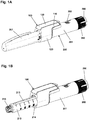
- Figs. 1A and 1B show a pen-formed drug delivery device 200 on which an electronic logging module 100 is mounted.
- the device represents a "generic" drug delivery device providing a specific example of a device in combination with which embodiments of the present invention is intended to be used or which can form a basis for aspects of the present invention.
- the logging module 100 comprises a body portion 110 and a ring-formed portion 120 allowing the module to be mounted on a generally cylindrical pen device.
- the body portion comprises electronic circuitry and sensor means allowing a property to be detected representing an amount of drug being expelled from the cartridge, as well as a display 130 for displaying data to a user.
- the ring portion comprises coupling means allowing the module to be securely and correctly mounted on the pen body.
- the electronic circuitry and the sensor means may in part be arranged in the ring portion.
- the drug delivery device may have to be adapted specifically to allow the given property to be detected.
- the drug delivery device may be provided with a magnet rotating during dose expelling, the logging module being adapted to detect the amount of rotation, see below.
- the pen device 200 comprises a cap part 207 and a main part having a proximal body or drive assembly portion with a housing 201 in which a drug expelling mechanism is arranged or integrated, and a distal cartridge holder portion in which a drug-filled transparent cartridge 213 with a distal needle-penetrable septum is arranged and retained in place by a non-removable cartridge holder attached to the proximal portion, the cartridge holder having openings allowing a portion of the cartridge to be inspected as well as distal coupling means 215 allowing a needle assembly to be releasably mounted.
- the cartridge is provided with a piston driven by a piston rod forming part of the expelling mechanism and may for example contain an insulin, GLP-1 or growth hormone formulation.
- a proximal-most rotatable dose member 280 serves to manually set (or dial) a desired dose of drug shown in display window 202 and which can then be expelled when the button 290 is actuated.
- the expelling mechanism may comprise a spring as in the shown embodiment which is strained during dose setting and then released to drive the piston rod when the release button is actuated.
- the expelling mechanism may be fully manual in which case the dose member and the actuation button moves proximally during dose setting corresponding to the set dose size, and then is moved distally by the user to expel the set dose.
- Figs. 1A and 1B show a drug delivery device of the pre-filled type, i.e. it is supplied with a pre-mounted cartridge and is to be discarded when the cartridge has been emptied.
- the drug delivery device may be designed to allow a loaded cartridge to be replaced, e.g. in the form of a "rear-loaded” drug delivery device in which the cartridge holder is adapted to be removed from the device main portion, or alternatively in the form of a "front-loaded” device in which a cartridge is inserted through a distal opening in the cartridge holder which is non-removably attached to the main part of the device.
- the module comprises a main body 310 having a generally cylindrical ring-formed portion 320 and a body portion 330 together forming a chassis on which the majority of the electronic circuitry is mounted.
- the main body is formed from a LDS polymer whereby integrated wiring can be achieved by using LDS (Laser Direct Structuring) technology, the polymer having elastic properties allowing a flexible hinged latch to be formed integrally.
- LDS Laser Direct Structuring
- the electronics including the sensors may be mounted on a flexible PCB which then is mounted on the main body 310 using e.g. metal clips.
- a flexible PCB may be mounted by fully or partly bonding it to a chassis component using double-sided adhesive, this allowing an accurate, reliable and compact design.
- the ring portion comprises an inner generally cylindrical surface adapted to be mounted on a drug delivery pen body as well as a pair of opposed integrally formed coupling structures 321 adapted to engage corresponding coupling structures on the pen device to assure that the module is securely mounted.
- the distal part of the ring portion has a larger diameter with a distally facing circumferential stop surface 329 adapted to receive and engage a cap when the module is mounted on a pen, see below.
- Each coupling structure on the module is in the form of a latch having a proximal portion 323, a distal portion 324 and a central portion, the latter being pivotally connected to the ring portion by integrally formed flexible hinges 325 allowing the latch to pivot a few degrees corresponding to a circumferential axis.
- the proximal latch portions each comprises an inner protrusion 326 adapted to engage a corresponding coupling structure on the pen device (e.g.
- protrusions otherwise used for attachment of the cap each comprises a protrusion 327 adapted to frictionally engage the cap outer surface when a cap is mounted after use.
- the cap outer surface may be provided with coupling means, e.g. a circumferential groove, allowing the cap to engage the logging module by snap action.
- the logging module when the logging module is mounted on the drug delivery pen body, the cap attaches to the logging module and not the pen body.
- the logging module may allow the cap to be attached directly to the pen body.
- the shown module is provided with a funnel-shaped slot adapted to axially engage a corresponding protrusion on the pen.
- a protrusion is provided on the pen cartridge holder 210 and arranged opposite the pen display window 202, the electronic display 130 thereby being arranged next to the pen display window when the module is mounted on a pen.
- the interactions between the logging module, the pen body and the cap will be described in greater detail below.
- the majority of the electronic components 340 including processors means with associated memory means, a display module 341 with a display 360, a cap switch 342 for detecting the presence of a mounted cap, a main switch (not shown) for detecting that the logging module is mounted on a pen body, and an energy source 343 are mounted.
- the latter may be in the form of a non-replaceable device life-time "battery", a replaceable battery or in the form of a rechargeable battery.
- the LCD is of a traditional stiff type to be covered by a separate display window, however, alternatively a flexible LCD may be bonded directly to a transparent plastic cover providing a compact and robust design.
- a sound generator e.g. a piezo beeper, may be provided to signal different states and/or error conditions to the user.
- the logging module is provided with a first sensor assembly comprising three "compass" sensor units 345 mounted equidistantly on the ring portion 320, each sensor unit being in the form of a magnetometer adapted to measure a magnetic field corresponding to three axes. Another type and number of sensors arranged in another pattern may be used.
- the sensor system is designed to detect the amount of rotation of a magnetic member arranged inside the drug delivery device for which the logging module has been specifically designed, such a system being described in greater detail in PCT application EP 2014/056724 .
- Further sensors may be provided allowing e.g. the type of the device (and thereby the drug) to be recognized, this being relevant if e.g. the drug delivery device is sold with a given drug in different concentrations such as insulin with 100 or 200 IU per ml.
- the logging module and the drug delivery device may be provided with mechanical coding means allowing a given logging module to be mounted only on a drug delivery device specifically coded for use with that logging module.
- the logging module comprises a ring-formed portion providing a bore adapted to receive a drug delivery device.
- the ring may be open and provided with a releasable closure member as disclosed in e.g. WO 2010/ 037828 .
- the logging module may be provided with user input means in the form of e.g. one or more buttons (not shown) allowing the user to control the module.
- the logging module may further be provided with transmission means allowing data to be transmitted to or from the module, e.g. log data may be transmitted to a user's smartphone by NFC or other wireless means.
- Fig. 3 shows an exemplary embodiment of a display 360 with all segments turned on. More specifically, the display comprises a dose size field 361 for showing a dose size in IU, a time field 362 having a stopwatch format HH:MM:SS, a "ready" symbol 363, and an "information” symbol 364. Exemplary use of the different display segments will be given below with reference to fig. 4 .
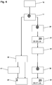
- fig. 4 a flow-chart is shown in which different aspects of the logging module user interface is illustrated, i.e. how the different features of the logging module is used to provide a logging module which in combination with a corresponding drug delivery device, e.g. as shown in figs. 1A and 1B , is both easy to use and energy efficient, the latter being a requirement especially in case the logging module is provided with a non-exchangeable energy source intended to power the module for its intended life-time, e.g. three years of normal use for the average user.
- a non-exchangeable energy source intended to power the module for its intended life-time, e.g. three years of normal use for the average user.
- the display 10 When the mounted logging module is in its sleeping state the display 10 is blank with no segments active.
- the display 11 shows the "ready" symbol indicating that the sensor system is now turned on and the logging module is ready to detect and store a dose to be expelled.
- dose setting and subsequent dose expelling the display 20 does not change but merely shows the ready symbol.
- the display 21 shows the expelled dose size in the dose size field, e.g. 20 IU as shown, together with a time value in the time field, e.g. 8 seconds as shown.
- the ready symbol is turned off. After a given number of seconds, e.g. 20 seconds, the display 22 is turned off. If the user later desires to check the latest log entry, i.e. dose size and time-since-last-dose, he or she activates the cap switch by moving the cap out of its mounted position thereby turning on the ready symbol in the display 30 and moves it back to its mounted position, the display 31 showing the last detected dose size together with the actual time-since-last-dose, e.g. 20 IU expelled 9 hours, 11 minutes and 29 seconds ago. To save energy the sensor system may be turned on with a delay of e.g. a few seconds, this allowing the user to check the latest log entry without the sensor system being turned on.
- the sensor system will time out and turn off after a certain amount of time, e.g. 5 minutes, after which the ready symbol in the display 40 is turned off.
- the logging module may be designed to re-start the timer for each successful detection of an expelled dose, this allowing the user time to split a given dose into two or more doses.
- the blank display indicates to the user that the sensor system has been turned off, the drug delivery device can be used as usual to set and expel a desired dose, however, the sensor system will remain turned off and the display 41 will remain blank. However, in order to remind the user that any dose that may have been expelled during a time-out period has not been logged, the display 42 will turn on the information "i" symbol.
- the user is presented with the "i" symbol when the cap is mounted again after a sensor time-out event. If the logging module is provided with an audible alarm, e.g. a beeper, the alarm may be sounded as well. In case the time-out appears after a successful detection of an expelled dose, the "i" will still be shown when the cap is put on, however, the detected dose has been stored and can be recalled as described below. Alternatively the "i" symbol may be replaced with a symbol more directly indicating an error condition.
- an audible alarm e.g. a beeper
- exemplary logging module features i.e. (i) display showings during normal use, and (ii) display showing after a sensor time-out event.
- Each of the two features may be implemented alone or in combination for a given logging module.
- the display symbols and number fields can be used in additional ways.
- the "i" symbol may be used in combination with a value shown in the dose size field to generate a number of codes, e.g. to indicate an error during dose sensing, a low battery condition or information in respect of data transfer, see below.
- the "i" may be used to indicate that doses have been combined.
- Fig. 5 shows a drug delivery pen 200 provided with a logging module 100 of the type described above with reference to figs. 1-4 and arranged next to a smartphone 400 configured to receive logging data from the logging module via wireless communication, e.g. NFC.
- the logging module is provided with a display configured to indicate the size of the last dose and the time since the last dose using the stopwatch display mode.
- the smartphone In order to communicate with the logging module the smartphone has been provided with specific "insulin diary" software.
- the smartphone NFC transmitter When the software is activated to initiate data transfer the smartphone NFC transmitter will transmit specific code which will wake up any nearby logging module which will then retransmit a unique code identifying the specific module. If a specific code is received for the first time the user is asked to confirm pairing and is asked to select from a list the given drug that should be associated with the given logging module, e.g. "Mix 30" as shown.
- the logging module may be designed to work with only one type of pen containing only one specific type of drug, the type of drug being transmitted during initial pairing, or the logging module may be provided with the ability to identify different types of pens and thus different types of drugs.
- log data from a logging module associated with a Mix 30 insulin has been transferred. Transfer may be controlled entirely by the smartphone, the logging module merely transmitting data when requested to do so. For example, when controlled to transfer logging data the logging module may transmit the entire memory content each time, e.g. 30 logging events, the smartphone being adapted to identify new log entries since last transfer.
- the stored logging data may comprise all determined dose amounts, i.e. including air shots and dose amounts determined in a sensor time-out event but before the sensors were turned off.
- first and second amounts 402 of Mix 30 has been delivered with the time and amount shown for each delivery. It may be indicated if a given dose amount is based on combined dose amounts.
- time information for each log entry may be generated by the smartphone based on relative time information provided by the logging module.
- an electronic logging module adapted to be mounted on a pen-formed drug delivery device has been described, however, the components of the module may alternatively be incorporated in a drug delivery device forming a unitary device. As such a device will comprise only a single housing the over-all volume may be reduced.
Description
- The present invention generally relates to medical devices for which the generation, collecting and storing of data are relevant. In specific embodiments the invention relates to devices and systems for capturing and organizing drug delivery dose data in an efficient and user-friendly way.
- In the disclosure of the present invention reference is mostly made to drug delivery devices used e.g. in the treatment of diabetes by delivery of insulin, however, this is only an exemplary use of the present invention.
- Drug injection devices have greatly improved the lives of patients who must self-administer drugs and biological agents. Drug injection devices may take many forms, including simple disposable devices that are little more than an ampoule with an injection means or they may be durable devices adapted to be used with pre-filled cartridges. Regardless of their form and type, they have proven to be great aids in assisting patients to self-administer injectable drugs and biological agents. They also greatly assist care givers in administering injectable medicines to those incapable of performing self-injections.
- Performing the necessary insulin injection at the right time and in the right size is essential for managing diabetes, i.e. compliance with the specified insulin regimen is important. In order to make it possible for medical personnel to determine the effectiveness of a prescribed dosage pattern, diabetes patients are encouraged to keep a log of the size and time of each injection. However, such logs are normally kept in handwritten notebooks, from which the logged information may not be easily uploaded to a computer for data processing. Furthermore, as only events, which are noted by the patient, are logged, the note book system requires that the patient remembers to log each injection, if the logged information is to have any value in the treatment of the patient's disease. A missing or erroneous record in the log results in a misleading picture of the injection history and thus a misleading basis for the medical personnel's decision making with respect to future medication. Accordingly, it may be desirable to automate the logging of ejection information from medication delivery systems based on the assumption that ejected doses corresponds to injected doses.
- Though some injection devices integrate this monitoring/acquisition mechanism into the device itself, e.g. as disclosed in
US 2009/0318865 andWO 2010/052275 , most devices of today are without it. The most widely used devices are purely mechanical devices either durable or prefilled. The latter devices are to be discarded after being emptied and so inexpensive that it is not cost-effective to build-in electronic data acquisition functionality in the device it-self. Addressing this problem a number of solutions have been proposed which would help a user to generate, collect and distribute data indicative of the use of a given medical device.
For example,WO 2007/107564 describes an electronic "add-on" module adapted to be attached to and measure signals generated by a standard mechanical pen device, the module relying on e.g. the sounds inherently produced by such a device during operation.WO 2010/ 037828 upon which the two-part form of the independent claims is based discloses a further add-on module adapted to be mounted on a pen device and create a time log for data representing sizes of doses expelled by the drug expelling mechanism of the pen device.WO 2011/157561 discloses another "add-on" module which turns off automatically after a predetermined amount of time. Alternatively, in order to provide pre-filled drug delivery devices which more reliably allow detection of an out-dosed amount of drug, it has been proposed to modify such pre-filled drug delivery devices to provide them with structures making them more suitable for cooperation with external detection means, thereby providing more reliable and accurate determination of out-dosed drug amounts. For example,PCT/EP2012/069729
Having regard to the above, it is an object of the present invention to provide systems, devices and methods allowing capturing and organizing drug delivery dose data in an efficient and user-friendly way. - In the disclosure of the present invention, embodiments and aspects will be described which will address one or more of the above objects or which will address objects apparent from the below disclosure as well as from the description of exemplary embodiments.
Thus, in a general aspect of the invention a logging device is provided, the logging device being adapted to be releasably attached to a drug delivery device or being formed integrally therewith (i.e. not to be detached by a user), the drug delivery device comprising a drug reservoir or means for receiving a drug reservoir, the drug reservoir comprising an outlet portion, a detachable cap adapted to cover the drug reservoir outlet portion in a mounted position, and drug expelling means comprising dose setting means allowing a user to set a dose amount of drug to be expelled. The logging device further comprises electronic circuitry comprising sensor means adapted to capture a property value related to a dose amount of drug expelled from a reservoir by the expelling means during an expelling event when the logging device has been attached to a drug delivery device, processor means adapted to determine dose amounts based on captured property values, memory means adapted to store at least one dose amount, display means adapted to display (i) a determined dose amount and/or a time value, and (ii) a warning message, and switch means adapted to be operated, when the logging device has been attached to a drug delivery device or is formed integrally therewith, between an off-state when the cap is in the mounted position and an on-state when the cap has been detached. A given dose amount may be stored in the memory in the form of e.g. the "native" detected property representing an amount of drug or as a calculated amount of drug. In such a device the sensor means is turned on when the switch is operated from the off- to the on-state, the sensor means is turned off when the switch is operated from the onto the off-state, the sensor means is turned off automatically when a predetermined amount of time has lapsed, and the display means is turned on to display a warning message when the switch is operated from the on- to the off-state and the sensor means has been turned off automatically, the warning message indicating to a user that an expelled dose may not have been captured. - Correspondingly, in a first specific aspect of the invention a logging device adapted to be releasably attached to a drug delivery device is provided, the drug delivery device comprising a drug reservoir or means for receiving a drug reservoir, the drug reservoir comprising an outlet portion, a detachable cap adapted to cover the drug reservoir outlet portion in a mounted position, drug expelling means comprising dose setting means allowing a user to set a dose amount of drug to be expelled, and electronic circuitry adapted to create a log of expelled dose amounts of drug. The electronic circuitry comprises sensor means adapted to capture a property value related to a dose amount of drug expelled from a reservoir by the expelling means during an expelling event when the logging device has been attached to a drug delivery device, processor means adapted to determine dose amounts based on captured property values, memory means adapted to store at least one dose amount, display means adapted to display a determined dose amount and/or a time value as well as a warning message, the electronic circuitry further comprising switch means. A time value may be associated with each stored dose amount. With the logging device attached to a drug delivery device the switch means is adapted to be operated between an off-state when the cap is in the mounted position and an on-state when the cap has been detached. In such an arrangement the sensor means is turned on when the switch is operated from the off- to the on-state, the sensor means is turned off when the switch is operated from the on- to the off-state, the sensor means is turned off automatically when a predetermined amount of time has lapsed, and the display means is turned on to display a warning message when the switch is operated from the on- to the off-state and the sensor means has been turned off automatically, the warning message indicating to a user that an expelled dose may not have been captured.
- The predetermined amount of time is initially counted from when the cap is removed, however, the counter may be reset when a given event is detected, e.g. a successful logging of an expelled dose of drug, this allowing a user to divide a given dose into split doses without "time constraints".
- As appears, an add-on device mounted to a pen device is turned on when the cap is removed, and after a given amount of time in inactivity the add-on device is turned off automatically, this to save energy. However, after this has happened the user may take a dose of drug which is then not detected as the add-on device is only turned on when the cap is removed. By providing a warning message when the cap is re-mounted after the sensor means has been turned off automatically, the warning message indicates to a user that an expelled dose may not have been captured, this allowing the user to take appropriate action if a dose was actually expelled.
- When the cap is re-mounted after a "normal" use event, the display means may display a determined dose amount together with a time value. Alternatively, only a dose amount or only a time value may be shown. The time may be a real time value or the time since a given dose amount was stored.
- In an exemplary embodiment the display means is turned on for a predetermined amount of time to display a message when the switch is operated from the on- to the off-state, the message being in the form of the last determined dose amount and/or a time value when the display is turned on without the sensor means having been turned off automatically, or the warning message when the display is turned on with the sensor means being turned off automatically. To save energy the sensor means may be turned on with a time delay when the switch is operated from the off- to the on-state, this allowing the user to check the latest log value without turning on the sensor system.
- Addressing the situation in which he user desires to split a given (large) dose, stored dose amounts determined within a given time period may be combined to a single combined dose amount. The given time period may be initiated by a detected expelling event taking place a given amount of time after a previous detected expelling event, or after a given detected action.
- When two or more dose amounts are determined within a given time period they may be combined automatically, or the user may be prompted to accept that the two or more dose amounts determined within a given time period are combined. Combined amounts may be indicated as such in the display. A determined dose amount below a given value, e.g. below 2 or 3 units of insulin, may be estimated to be a priming or an air shot and thus not combined as a log entry. When a combined dose amount is calculated and stored the individual doses may remain stored and subsequently retrieved when desired. The stored and retrievable data may comprise all determined dose amounts, i.e. including air shots and dose amounts determined in a sensor time-out event but before the sensors were turned off. A time value may be associated with each stored dose amount. For a combined dose e.g. the last time value may be used. The electronic circuitry may comprise transmitter means adapted to transmit stored data to an external receiver, e.g. by means of NFC or Bluetooth.
- The sensor means may be adapted to capture a property value in the form of an amount of rotation of a magnetic member arranged in the drug delivery device, the amount of rotation of the magnetic member corresponding to the amount of drug expelled from a reservoir by the expelling means. The electronic circuitry may comprise transmitter means adapted to transmit stored data to an external receiver, e.g. by means of NFC.
- The above-described logging device may be provided in combination with a drug delivery device, thereby forming a drug delivery system, the drug delivery device comprising a drug reservoir or means for receiving a drug reservoir, the drug reservoir comprising an outlet portion, a detachable cap adapted to cover the drug reservoir outlet portion in a mounted position, and drug expelling means comprising dose setting means allowing a user to set a dose amount of drug to be expelled, wherein the logging device is releasably attachable to the drug delivery device.
- In an exemplary embodiment the drug delivery device further comprises an identifier, e.g. a colour or in the form of a barcode, representing information for the specific drug type contained in the reservoir or the specific drug delivery device, with the logging device further comprising means for capturing information from the identifier, wherein the electronic circuitry is adapted to create a log for a given identifier.
- In a further specific aspect of the invention a drug delivery system is provided, comprising a drug reservoir or means for receiving a drug reservoir, the drug reservoir comprising an outlet portion, a detachable cap adapted to cover the drug reservoir outlet portion in a mounted position, drug expelling means comprising dose setting means allowing a user to set a dose amount of drug to be expelled, electronic circuitry comprising sensor means adapted to capture a property value related to the dose amount of drug expelled from the reservoir by the expelling means during an expelling event, processor means adapted to determine dose amounts based on captured property values, memory means adapted to store at least one dose amount, display means adapted to display a determined dose amount and/or a time value, and a warning message, and switch means adapted to be operated between an off-state when the cap is in the mounted position and an on-state when the cap has been detached from the system, wherein the sensor means is turned on when the switch is operated from the off- to the on-state, the sensor means is turned off when the switch is operated from the on- to the off-state, the sensor means is turned off automatically when a predetermined amount of time has lapsed, and the display means is turned on to display a warning message when the switch is operated from the on- to the off-state and the sensor means has been turned off automatically, the warning message indicating to a user that an expelled dose may not have been captured.
- The system may be in the form of an integrated drug delivery device comprising the drug reservoir or means for receiving a drug reservoir, the drug expelling means, and the electronic circuitry. The integrated device may be provided with the above-described features of a separate logging device.
- In order to capture a property value related to a dose amount of drug expelled a number of technologies could be used. For example, for an integrated arrangement capture could be based on galvanic contacts, optical sensors or magnetic sensors. Indeed, for an external attachable logging device the same principles could be used, however, by using magnetic detection it would be possible to detect movements inside the delivery device without having to provide openings or contacts in the housing wall. For a given expelling mechanism a number of components will normally be moved corresponding to an expelled amount of drug, e.g. a piston rod will move axially and a drive member for moving the piston rod may rotate. Correspondingly, a property value could be either axial displacement or amount of rotation, or a combination of both. For example, if a given component may rotate more than 360 degrees in order to expel a given dose, the amount of rotation may be captured by counting increments or, alternatively, by determining the rotational position of the rotating component and combine it with information relating to the number of full rotations or the axial position of an axially moved component.
- In the context of the present application and as used in the specification and the claims, the term processor means covers any combination of electronic circuitry suitable for providing the specified functionality, e.g. processing and storing data as well as controlling all connected input and output devices. A processor will typically comprise one or more CPUs or microprocessors which may be supplemented by additional devices for support, memory or control functions. For example, in case a communication interface is provided (e.g. wireless), the transmitter and receiver may be fully or partly integrated with a processor, or may be provided by individual units. Each of the components making up the processor circuitry may be special purpose or general purpose devices. The term display means covers any type of display capable of visually providing the specified functionality, e.g. a LCD or OLED.
- As used herein, the term "insulin" is meant to encompass any drug-containing flowable medicine capable of being passed through a delivery means such as a cannula or hollow needle in a controlled manner, such as a liquid, solution, gel or fine suspension, and which has a blood glucose controlling effect, e.g. human insulin and analogues thereof as well as non-insulins such as GLP-1 and analogues thereof. In the description of exemplary embodiments reference will be made to the use of insulin.
- In the following exemplary embodiments of the invention will be described with reference to the drawings, wherein
-
figs. 1A and 1B show a pen-formed drug delivery device with an electronic logging module, -
fig. 2 shows the interior of a logging module, -
fig. 3 shows a display with all segments active, -
fig. 4 shows a flowchart with display readings during different operational states, and -
fig. 5 shows a drug delivery pen provided with a logging module and in communication with a smartphone. - In the figures like structures are mainly identified by like reference numerals.
- When in the following terms such as "upper" and "lower", "right" and "left", "horizontal" and "vertical" or similar relative expressions are used, these only refer to the appended figures and not necessarily to an actual situation of use. The shown figures are schematic representations for which reason the configuration of the different structures as well as their relative dimensions are intended to serve illustrative purposes only. When the term member or element is used for a given component it generally indicates that in the described embodiment the component is a unitary component, however, the same member or element may alternatively comprise a number of sub-components just as two or more of the described components could be provided as unitary components, e.g. manufactured as a single injection moulded part. The term "assembly" does not imply that the described components necessarily can be assembled to provide a unitary or functional assembly during a given assembly procedure but is merely used to describe components grouped together as being functionally more closely related.
-
Figs. 1A and 1B show a pen-formeddrug delivery device 200 on which anelectronic logging module 100 is mounted. In the present context the device represents a "generic" drug delivery device providing a specific example of a device in combination with which embodiments of the present invention is intended to be used or which can form a basis for aspects of the present invention. - More specifically, the
logging module 100 comprises abody portion 110 and a ring-formedportion 120 allowing the module to be mounted on a generally cylindrical pen device. The body portion comprises electronic circuitry and sensor means allowing a property to be detected representing an amount of drug being expelled from the cartridge, as well as adisplay 130 for displaying data to a user. The ring portion comprises coupling means allowing the module to be securely and correctly mounted on the pen body. The electronic circuitry and the sensor means may in part be arranged in the ring portion. Depending on the sensor means provided in the logging module and the property to be detected, the drug delivery device may have to be adapted specifically to allow the given property to be detected. For example, the drug delivery device may be provided with a magnet rotating during dose expelling, the logging module being adapted to detect the amount of rotation, see below. - The
pen device 200 comprises acap part 207 and a main part having a proximal body or drive assembly portion with ahousing 201 in which a drug expelling mechanism is arranged or integrated, and a distal cartridge holder portion in which a drug-filledtransparent cartridge 213 with a distal needle-penetrable septum is arranged and retained in place by a non-removable cartridge holder attached to the proximal portion, the cartridge holder having openings allowing a portion of the cartridge to be inspected as well as distal coupling means 215 allowing a needle assembly to be releasably mounted. The cartridge is provided with a piston driven by a piston rod forming part of the expelling mechanism and may for example contain an insulin, GLP-1 or growth hormone formulation. A proximal-mostrotatable dose member 280 serves to manually set (or dial) a desired dose of drug shown indisplay window 202 and which can then be expelled when thebutton 290 is actuated. Depending on the type of expelling mechanism embodied in the drug delivery device, the expelling mechanism may comprise a spring as in the shown embodiment which is strained during dose setting and then released to drive the piston rod when the release button is actuated. Alternatively the expelling mechanism may be fully manual in which case the dose member and the actuation button moves proximally during dose setting corresponding to the set dose size, and then is moved distally by the user to expel the set dose. -
Figs. 1A and 1B show a drug delivery device of the pre-filled type, i.e. it is supplied with a pre-mounted cartridge and is to be discarded when the cartridge has been emptied. In alternative embodiments the drug delivery device may be designed to allow a loaded cartridge to be replaced, e.g. in the form of a "rear-loaded" drug delivery device in which the cartridge holder is adapted to be removed from the device main portion, or alternatively in the form of a "front-loaded" device in which a cartridge is inserted through a distal opening in the cartridge holder which is non-removably attached to the main part of the device. - Turning to
fig. 2 an exemplary embodiment of alogging module 300 is shown in which the exterior housing has been removed to reveal the interior design and components. The module comprises amain body 310 having a generally cylindrical ring-formedportion 320 and abody portion 330 together forming a chassis on which the majority of the electronic circuitry is mounted. The main body is formed from a LDS polymer whereby integrated wiring can be achieved by using LDS (Laser Direct Structuring) technology, the polymer having elastic properties allowing a flexible hinged latch to be formed integrally. Alternatively, the electronics including the sensors may be mounted on a flexible PCB which then is mounted on themain body 310 using e.g. metal clips. As a further alternative a flexible PCB may be mounted by fully or partly bonding it to a chassis component using double-sided adhesive, this allowing an accurate, reliable and compact design. The ring portion comprises an inner generally cylindrical surface adapted to be mounted on a drug delivery pen body as well as a pair of opposed integrally formedcoupling structures 321 adapted to engage corresponding coupling structures on the pen device to assure that the module is securely mounted. The distal part of the ring portion has a larger diameter with a distally facingcircumferential stop surface 329 adapted to receive and engage a cap when the module is mounted on a pen, see below. - The inner ring surface and the outer pen body surface may be in either form-fitting or slight frictional engagement. Each coupling structure on the module is in the form of a latch having a
proximal portion 323, adistal portion 324 and a central portion, the latter being pivotally connected to the ring portion by integrally formedflexible hinges 325 allowing the latch to pivot a few degrees corresponding to a circumferential axis. By this arrangement the distal latch portion moves inwards when the proximal portion is moved outwards and vice versa. The proximal latch portions each comprises aninner protrusion 326 adapted to engage a corresponding coupling structure on the pen device (e.g. protrusions otherwise used for attachment of the cap) and the distal latch portions each comprises aprotrusion 327 adapted to frictionally engage the cap outer surface when a cap is mounted after use. Alternatively the cap outer surface may be provided with coupling means, e.g. a circumferential groove, allowing the cap to engage the logging module by snap action. As appears for the shown embodiment, when the logging module is mounted on the drug delivery pen body, the cap attaches to the logging module and not the pen body. In alternative embodiments, the logging module may allow the cap to be attached directly to the pen body. To assure correct rotational mounting of the module on the pen the shown module is provided with a funnel-shaped slot adapted to axially engage a corresponding protrusion on the pen. In the shown embodiment offig. 1A a protrusion is provided on thepen cartridge holder 210 and arranged opposite thepen display window 202, theelectronic display 130 thereby being arranged next to the pen display window when the module is mounted on a pen. The interactions between the logging module, the pen body and the cap will be described in greater detail below. - On the
body portion 330 the majority of theelectronic components 340 including processors means with associated memory means, adisplay module 341 with adisplay 360, acap switch 342 for detecting the presence of a mounted cap, a main switch (not shown) for detecting that the logging module is mounted on a pen body, and anenergy source 343 are mounted. The latter may be in the form of a non-replaceable device life-time "battery", a replaceable battery or in the form of a rechargeable battery. In the shown embodiment the LCD is of a traditional stiff type to be covered by a separate display window, however, alternatively a flexible LCD may be bonded directly to a transparent plastic cover providing a compact and robust design. In addition to the LCD a sound generator, e.g. a piezo beeper, may be provided to signal different states and/or error conditions to the user. - In the shown embodiment the logging module is provided with a first sensor assembly comprising three "compass"
sensor units 345 mounted equidistantly on thering portion 320, each sensor unit being in the form of a magnetometer adapted to measure a magnetic field corresponding to three axes. Another type and number of sensors arranged in another pattern may be used. In the shown embodiment the sensor system is designed to detect the amount of rotation of a magnetic member arranged inside the drug delivery device for which the logging module has been specifically designed, such a system being described in greater detail inPCT application EP 2014/056724 - Further sensors may be provided allowing e.g. the type of the device (and thereby the drug) to be recognized, this being relevant if e.g. the drug delivery device is sold with a given drug in different concentrations such as insulin with 100 or 200 IU per ml. Alternatively, the logging module and the drug delivery device may be provided with mechanical coding means allowing a given logging module to be mounted only on a drug delivery device specifically coded for use with that logging module.
- In the shown embodiment the logging module comprises a ring-formed portion providing a bore adapted to receive a drug delivery device. Alternatively the ring may be open and provided with a releasable closure member as disclosed in e.g.
WO 2010/ 037828 . - The logging module may be provided with user input means in the form of e.g. one or more buttons (not shown) allowing the user to control the module. The logging module may further be provided with transmission means allowing data to be transmitted to or from the module, e.g. log data may be transmitted to a user's smartphone by NFC or other wireless means.
-
Fig. 3 shows an exemplary embodiment of adisplay 360 with all segments turned on. More specifically, the display comprises adose size field 361 for showing a dose size in IU, atime field 362 having a stopwatch format HH:MM:SS, a "ready"symbol 363, and an "information"symbol 364. Exemplary use of the different display segments will be given below with reference tofig. 4 . - Turning to
fig. 4 a flow-chart is shown in which different aspects of the logging module user interface is illustrated, i.e. how the different features of the logging module is used to provide a logging module which in combination with a corresponding drug delivery device, e.g. as shown infigs. 1A and 1B , is both easy to use and energy efficient, the latter being a requirement especially in case the logging module is provided with a non-exchangeable energy source intended to power the module for its intended life-time, e.g. three years of normal use for the average user. - When the mounted logging module is in its sleeping state the
display 10 is blank with no segments active. When the user removes the cap, thereby activating the cap switch, thedisplay 11 shows the "ready" symbol indicating that the sensor system is now turned on and the logging module is ready to detect and store a dose to be expelled. During dose setting and subsequent dose expelling thedisplay 20 does not change but merely shows the ready symbol. When the user after having expelled a dose again attaches the cap thedisplay 21 shows the expelled dose size in the dose size field, e.g. 20 IU as shown, together with a time value in the time field, e.g. 8 seconds as shown. As the latter has a stopwatch configuration with a running second counter it is apparent to the user that a "time-since-last-dose" is shown. At the same time the ready symbol is turned off. After a given number of seconds, e.g. 20 seconds, thedisplay 22 is turned off. If the user later desires to check the latest log entry, i.e. dose size and time-since-last-dose, he or she activates the cap switch by moving the cap out of its mounted position thereby turning on the ready symbol in thedisplay 30 and moves it back to its mounted position, thedisplay 31 showing the last detected dose size together with the actual time-since-last-dose, e.g. 20 IU expelled 9 hours, 11 minutes and 29 seconds ago. To save energy the sensor system may be turned on with a delay of e.g. a few seconds, this allowing the user to check the latest log entry without the sensor system being turned on. - To safe-guard low energy consumption the sensor system will time out and turn off after a certain amount of time, e.g. 5 minutes, after which the ready symbol in the
display 40 is turned off. The logging module may be designed to re-start the timer for each successful detection of an expelled dose, this allowing the user time to split a given dose into two or more doses. Although the blank display indicates to the user that the sensor system has been turned off, the drug delivery device can be used as usual to set and expel a desired dose, however, the sensor system will remain turned off and thedisplay 41 will remain blank. However, in order to remind the user that any dose that may have been expelled during a time-out period has not been logged, thedisplay 42 will turn on the information "i" symbol. As appears, whether or not a dose has been expelled, the user is presented with the "i" symbol when the cap is mounted again after a sensor time-out event. If the logging module is provided with an audible alarm, e.g. a beeper, the alarm may be sounded as well. In case the time-out appears after a successful detection of an expelled dose, the "i" will still be shown when the cap is put on, however, the detected dose has been stored and can be recalled as described below. Alternatively the "i" symbol may be replaced with a symbol more directly indicating an error condition. - With reference to
fig. 3 two exemplary logging module features have been described, i.e. (i) display showings during normal use, and (ii) display showing after a sensor time-out event. Each of the two features may be implemented alone or in combination for a given logging module. - In addition to the above-described use scenarios, the display symbols and number fields can be used in additional ways. For example, the "i" symbol may be used in combination with a value shown in the dose size field to generate a number of codes, e.g. to indicate an error during dose sensing, a low battery condition or information in respect of data transfer, see below. Further, if the logging module is adapted to combine split doses (see
EP 2014/ 056727 -
Fig. 5 shows adrug delivery pen 200 provided with alogging module 100 of the type described above with reference tofigs. 1-4 and arranged next to asmartphone 400 configured to receive logging data from the logging module via wireless communication, e.g. NFC. As described above, the logging module is provided with a display configured to indicate the size of the last dose and the time since the last dose using the stopwatch display mode. - In order to communicate with the logging module the smartphone has been provided with specific "insulin diary" software. When the software is activated to initiate data transfer the smartphone NFC transmitter will transmit specific code which will wake up any nearby logging module which will then retransmit a unique code identifying the specific module. If a specific code is received for the first time the user is asked to confirm pairing and is asked to select from a list the given drug that should be associated with the given logging module, e.g. "
Mix 30" as shown. Alternatively, the logging module may be designed to work with only one type of pen containing only one specific type of drug, the type of drug being transmitted during initial pairing, or the logging module may be provided with the ability to identify different types of pens and thus different types of drugs. In the shown embodiment log data from a logging module associated with aMix 30 insulin has been transferred. Transfer may be controlled entirely by the smartphone, the logging module merely transmitting data when requested to do so. For example, when controlled to transfer logging data the logging module may transmit the entire memory content each time, e.g. 30 logging events, the smartphone being adapted to identify new log entries since last transfer. The stored logging data may comprise all determined dose amounts, i.e. including air shots and dose amounts determined in a sensor time-out event but before the sensors were turned off. - When data has been successfully transmitted this may be indicated on the smartphone as well as on the logging module. In the exemplary user interface the user can toggle back and forth between different day views, each day view showing the different amounts of drug delivered together with a real time value. In
fig. 5 on a givenday 401 first andsecond amounts 402 ofMix 30 has been delivered with the time and amount shown for each delivery. It may be indicated if a given dose amount is based on combined dose amounts. To avoid having a real time clock in the logging module time information for each log entry may be generated by the smartphone based on relative time information provided by the logging module. - With reference to
figs. 1-5 an electronic logging module adapted to be mounted on a pen-formed drug delivery device has been described, however, the components of the module may alternatively be incorporated in a drug delivery device forming a unitary device. As such a device will comprise only a single housing the over-all volume may be reduced. - In the above description of exemplary embodiments, the different structures and means providing the described functionality for the different components have been described to a degree to which the concept of the present invention will be apparent to the skilled reader. The detailed construction and specification for the different components are considered the object of a normal design procedure performed by the skilled person along the lines set out in the present specification.
Claims (15)
- A logging device (100, 300) adapted to be releasably attached to a drug delivery device, the drug delivery device comprising a drug reservoir (213) or means for receiving a drug reservoir, the drug reservoir comprising an outlet portion, a detachable cap adapted to cover the drug reservoir outlet portion in a mounted position, and drug expelling means comprising dose setting means (280) allowing a user to set a dose amount of drug to be expelled, the logging device comprising:- electronic circuitry (340) comprising:wherein:- sensor means (345) adapted to capture a property value related to a dose amount of drug expelled from a reservoir by the expelling means during an expelling event when the logging device has been attached to a drug delivery device,- processor means adapted to determine dose amounts based on captured property values,- memory means adapted to store at least one dose amount,- display means (130, 360) adapted to display (i) a determined dose amount and/or a time value, and (ii) a warning message, and- switch means (342) adapted to be operated, when the logging device has been attached to a drug delivery device, between an off-state when the cap is in the mounted position and an on-state when the cap has been detached,- the sensor means is turned on when the switch is operated from the off- to the on-state, and- the sensor means is turned off when the switch is operated from the on- to the off-state, characterized in that- the sensor means is turned off automatically when a predetermined amount of time has lapsed, and- the display means is turned on to display a warning message when the switch is operated from the on- to the off-state and the sensor means has been turned off automatically, the warning message indicating to a user that an expelled dose may not have been captured.
- A logging device as in claim 1, wherein:- the display means is turned on for a predetermined amount of time to display a message when the switch is operated from the on- to the off-state, the message being in the form of:- the last determined dose amount and/or a time value when the display is turned on without the sensor means having been turned off automatically, or- the warning message when the display is turned on with the sensor means being turned off automatically.
- A logging device as in claim 1 or 2, wherein stored dose amounts determined within a given time period are combined or can be combined to a single combined dose amount, and the given time period is initiated by a detected expelling event taking place:- a given amount of time after a previously detected expelling event, or- after a given detected action.
- A logging device as in claim 3, wherein two or more dose amounts determined within a given time period are combined automatically.
- A logging device as in claim 3, wherein the user is prompted to accept that two or more dose amounts determined within a given time period are combined.
- A logging device as in any of claims 3-5, wherein a determined dose amount below a given value is estimated to be a priming or air shot and thus not combined with another log entry.
- A logging device as in any of claims 1-6, wherein the log comprises a time value associated with each stored dose amount.
- A logging device as in any of claims 1-7, wherein the sensor means is adapted to capture a property value in the form of an amount of rotation of a magnetic member arranged in the drug delivery device, the amount of rotation of the magnetic member corresponding to the amount of drug expelled from a reservoir by the expelling means.
- A logging device as in any of claims 1-8, wherein the sensor means is turned on with a time delay when the switch is operated from the off- to the on-state.
- A logging device as in any of the previous claims, in combination with a drug delivery device (200), thereby forming a drug delivery system, the drug delivery device comprising:- a drug reservoir (213) or means for receiving a drug reservoir, the drug reservoir comprising an outlet portion,- a detachable cap adapted to cover the drug reservoir outlet portion in a mounted position, and- drug expelling means comprising dose setting means (280) allowing a user to set a dose amount of drug to be expelled,wherein the logging device (100, 300) is releasably attachable to the drug delivery device.
- A drug delivery system (100, 200), comprising:- a drug reservoir (213) or means for receiving a drug reservoir, the drug reservoir comprising an outlet portion,- a detachable cap (207) adapted to cover the drug reservoir outlet portion in a mounted position,- drug expelling means comprising dose setting means allowing a user to set a dose amount of drug to be expelled,- electronic circuitry (340) comprising:wherein:- sensor means (345) adapted to capture a property value related to the dose amount of drug expelled from the reservoir by the expelling means during an expelling event,- processor means adapted to determine dose amounts based on captured property values,- memory means adapted to store at least one dose amount,- display means (130, 360) adapted to display (i) a determined dose amount and/or a time value, and (ii) a warning message, and- switch means (342) operatable between an off-state when the cap is in the mounted position and an on-state when the cap has been detached from the system,- the sensor means is turned on when the switch is operated from the off- to the on-state,- the sensor means is turned off when the switch is operated from the on- to the off-state, characterized in that- the sensor means is turned off automatically when a predetermined amount of time has lapsed, and- the display means is turned on to display a warning message when the switch is operated from the on- to the off-state and the sensor means has been turned off automatically, the warning message indicating to a user that an expelled dose may not have been captured.
- A drug delivery system as in claim 11, wherein the system is in the form of a drug delivery device comprising:- the drug reservoir or means for receiving a drug reservoir,- the drug expelling means, and- the electronic circuitry.
- A drug delivery system as in claims 11 or 12, wherein the sensor means is adapted to capture a property value in the form of an amount of rotation of a magnetic member arranged in the drug delivery device, the amount of rotation of the magnetic member corresponding to the amount of drug expelled from a reservoir by the expelling means.
- A drug delivery system as in any of claims 11-13, wherein two or more dose amounts determined within a given time period are combined automatically.
- A drug delivery system as in any of claims 11-14, the drug delivery device further comprising:- an identifier representing information for the specific drug type contained in the reservoir or the specific drug delivery device,- the logging device further comprising means (340) for capturing information from the identifier,- wherein the electronic circuitry is adapted to create a log for a given identifier.
Applications Claiming Priority (2)
| Application Number | Priority Date | Filing Date | Title |
|---|---|---|---|
| EP14171456 | 2014-06-06 | ||
| PCT/EP2015/062499 WO2015185687A1 (en) | 2014-06-06 | 2015-06-04 | Logging device for drug delivery device |
Publications (2)
| Publication Number | Publication Date |
|---|---|
| EP3151880A1 EP3151880A1 (en) | 2017-04-12 |
| EP3151880B1 true EP3151880B1 (en) | 2018-05-16 |
Family
ID=50979536
Family Applications (1)
| Application Number | Title | Priority Date | Filing Date |
|---|---|---|---|
| EP15726194.2A Active EP3151880B1 (en) | 2014-06-06 | 2015-06-04 | Logging device for drug delivery device |
Country Status (5)
| Country | Link |
|---|---|
| US (2) | USRE49438E1 (en) |
| EP (1) | EP3151880B1 (en) |
| JP (1) | JP6568113B2 (en) |
| CN (1) | CN106659842B (en) |
| WO (1) | WO2015185687A1 (en) |
Cited By (1)
| Publication number | Priority date | Publication date | Assignee | Title |
|---|---|---|---|---|
| WO2022262992A1 (en) | 2021-06-18 | 2022-12-22 | Sanofi | A method and system for associating dose related data captured with and stored in an add-on device to a drug delivery device |
Families Citing this family (26)
| Publication number | Priority date | Publication date | Assignee | Title |
|---|---|---|---|---|
| WO2015185687A1 (en) | 2014-06-06 | 2015-12-10 | Novo Nordisk A/S | Logging device for drug delivery device |
| JP6568112B2 (en) * | 2014-06-06 | 2019-08-28 | ノボ・ノルデイスク・エー/エス | Recording device actuated by a drug delivery device |
| US20170182258A1 (en) * | 2015-12-29 | 2017-06-29 | InsuLog Ltd. | Adjunct device and system for an injector for monitoring injected amounts |
| EP3407940A4 (en) | 2016-01-29 | 2019-09-04 | Companion Medical, Inc. | Automatic medication delivery tracking |
| EP3222309A1 (en) * | 2016-03-22 | 2017-09-27 | Carebay Europe Ltd | Monitoring unit |
| WO2017189712A1 (en) * | 2016-04-28 | 2017-11-02 | Becton, Dickinson And Company | Smart medication delivery devices for providing users with delivery infomatics and methods of using same |
| WO2017186955A1 (en) | 2016-04-29 | 2017-11-02 | Novo Nordisk A/S | Drug delivery system with dose capturing |
| CN114099856A (en) | 2016-09-09 | 2022-03-01 | 赛诺菲-安万特德国有限公司 | Data collection device attached to an injection device |
| EP3548120B1 (en) * | 2016-12-05 | 2022-06-22 | Novo Nordisk A/S | Accessory device with pairing feature |
| JP7071394B2 (en) * | 2016-12-13 | 2022-05-18 | ベクトン・ディキンソン・アンド・カンパニー | Event recording device for drug administration equipment |
| JP2020519353A (en) * | 2017-05-09 | 2020-07-02 | ノボ・ノルデイスク・エー/エス | Drug delivery device with audio converter |
| KR102654708B1 (en) | 2017-11-23 | 2024-04-03 | 사노피 | Pharmaceutical injection device with rotary encoder |
| US10987464B2 (en) | 2017-12-12 | 2021-04-27 | Bigfoot Biomedical, Inc. | Pen cap for insulin injection pens and associated methods and systems |
| US11116899B2 (en) | 2017-12-12 | 2021-09-14 | Bigfoot Biomedical, Inc. | User interface for diabetes management systems and devices |
| US11083852B2 (en) | 2017-12-12 | 2021-08-10 | Bigfoot Biomedical, Inc. | Insulin injection assistance systems, methods, and devices |
| US11464459B2 (en) | 2017-12-12 | 2022-10-11 | Bigfoot Biomedical, Inc. | User interface for diabetes management systems including flash glucose monitor |
| EP3724888A1 (en) | 2017-12-12 | 2020-10-21 | Bigfoot Biomedical, Inc. | Therapy management systems, methods, and devices |
| US11077243B2 (en) | 2017-12-12 | 2021-08-03 | Bigfoot Biomedical, Inc. | Devices, systems, and methods for estimating active medication from injections |
| CN111526903B (en) * | 2017-12-28 | 2023-06-30 | 赛诺菲 | Mounting adapter for injection device and attachment device |
| JP2021515641A (en) * | 2018-03-09 | 2021-06-24 | ノボ・ノルデイスク・エー/エス | Transmission protocol for medical devices with log features |
| US20210042429A1 (en) * | 2018-04-03 | 2021-02-11 | Novo Nordisk A/S | Data Transmission Safety Feature |
| US20210220562A1 (en) * | 2018-05-18 | 2021-07-22 | Novo Nordisk A/S | Sensor assembly with identifier determination |
| US11948671B2 (en) | 2019-04-11 | 2024-04-02 | Medtronic Minimed, Inc. | Intelligent accessories for medicine dispensing device |
| EP3763406A1 (en) * | 2019-07-12 | 2021-01-13 | Sanofi | Method and electronic device for acquiring delivery information |
| JP2023547445A (en) * | 2020-10-30 | 2023-11-10 | ノボ・ノルデイスク・エー/エス | Dose logging sensor system with error detection function |
| US20220401656A1 (en) * | 2021-06-21 | 2022-12-22 | Medtronic Minimed, Inc. | Accessory devices, systems, and methods for medicine administration and tracking |
Family Cites Families (27)
| Publication number | Priority date | Publication date | Assignee | Title |
|---|---|---|---|---|
| AU1860697A (en) | 1995-09-08 | 1997-07-28 | Visionary Medical Products Corporation | Pen-type injector drive mechanism |
| RU2181299C2 (en) | 1996-02-23 | 2002-04-20 | Ново Нордиск А/С | Syringe with electronic parameter presentation |
| UA35653C2 (en) | 1996-03-12 | 2001-04-16 | Ново Нордіск А/С | Device for injection |
| ATE375175T1 (en) * | 1999-10-12 | 2007-10-15 | Novo Nordisk As | ELECTRONIC AIR INJECTIONS |
| EP1391794A1 (en) | 2002-07-23 | 2004-02-25 | Novo Nordisk A/S | Device with time indicating means |
| EP1640029A1 (en) * | 2004-09-24 | 2006-03-29 | Novo Nordisk A/S | Injection device with cap |
| DE102004063664A1 (en) | 2004-12-31 | 2006-07-20 | Tecpharma Licensing Ag | Real-time display of a device for metered administration of a product |
| JP5183620B2 (en) | 2006-03-20 | 2013-04-17 | ノボ・ノルデイスク・エー/エス | Electronic module for mechanical drug delivery device |
| CN102895718B (en) | 2006-09-29 | 2015-01-14 | 诺沃—诺迪斯克有限公司 | An injection device with electronic detecting means |
| EP2125075A2 (en) * | 2007-01-22 | 2009-12-02 | Intelliject, Inc. | Medical injector with compliance tracking and monitoring |
| EP2060284A1 (en) | 2007-11-13 | 2009-05-20 | F.Hoffmann-La Roche Ag | Medical injection device having data input means and a pivotable display |
| JP5396041B2 (en) | 2008-06-03 | 2014-01-22 | 株式会社バイオエコーネット | Ear thermometer |
| US7959598B2 (en) | 2008-08-20 | 2011-06-14 | Asante Solutions, Inc. | Infusion pump systems and methods |
| EP2349412B1 (en) * | 2008-10-01 | 2019-07-24 | Novo Nordisk A/S | Medical assembly with monitoring device |
| CA2738880A1 (en) * | 2008-11-06 | 2010-05-14 | Novo Nordisk A/S | Electronically assisted drug delivery device |
| WO2010098931A1 (en) | 2009-02-27 | 2010-09-02 | Lifescan, Inc. | Drug delivery management systems and methods |
| US20100286612A1 (en) | 2009-05-06 | 2010-11-11 | William Cirillo | Medication injection supervisor device |
| NL2005017C2 (en) * | 2010-07-01 | 2012-01-03 | Techlund Ab | Replaceable cap for a dosing device. |
| WO2013004844A1 (en) | 2011-07-07 | 2013-01-10 | Novo Nordisk A/S | Drug delivery injection pen with add-on dose capturing and display module |
| JP2014524297A (en) | 2011-08-18 | 2014-09-22 | ノボ・ノルデイスク・エー/エス | Drug delivery device having means for handling data |
| EP2572740A1 (en) | 2011-09-20 | 2013-03-27 | Roche Diagnostics GmbH | Drug injection devices and systems with an analyte measurement module |
| EP2763722B1 (en) * | 2011-10-07 | 2016-08-10 | Novo Nordisk A/S | System for determining position of element based on three-axial magnetic sensors |
| EP3178505B1 (en) * | 2012-12-13 | 2018-05-02 | Panasonic Healthcare Holdings Co., Ltd. | Medicament injection device |
| EP2981313B1 (en) | 2013-04-05 | 2017-06-14 | Novo Nordisk A/S | Drug delivery device and logging module assembly |
| EP3099350B1 (en) * | 2014-01-27 | 2019-06-12 | UCB Biopharma SPRL | Auto-injector |
| JP6568112B2 (en) * | 2014-06-06 | 2019-08-28 | ノボ・ノルデイスク・エー/エス | Recording device actuated by a drug delivery device |
| WO2015185687A1 (en) | 2014-06-06 | 2015-12-10 | Novo Nordisk A/S | Logging device for drug delivery device |
-
2015
- 2015-06-04 WO PCT/EP2015/062499 patent/WO2015185687A1/en active Application Filing
- 2015-06-04 JP JP2016571353A patent/JP6568113B2/en active Active
- 2015-06-04 US US17/127,987 patent/USRE49438E1/en active Active
- 2015-06-04 CN CN201580030182.XA patent/CN106659842B/en active Active
- 2015-06-04 EP EP15726194.2A patent/EP3151880B1/en active Active
- 2015-06-04 US US15/315,414 patent/US10159797B2/en not_active Ceased
Non-Patent Citations (1)
| Title |
|---|
| None * |
Cited By (1)
| Publication number | Priority date | Publication date | Assignee | Title |
|---|---|---|---|---|
| WO2022262992A1 (en) | 2021-06-18 | 2022-12-22 | Sanofi | A method and system for associating dose related data captured with and stored in an add-on device to a drug delivery device |
Also Published As
| Publication number | Publication date |
|---|---|
| USRE49438E1 (en) | 2023-02-28 |
| JP6568113B2 (en) | 2019-08-28 |
| EP3151880A1 (en) | 2017-04-12 |
| JP2017520303A (en) | 2017-07-27 |
| CN106659842B (en) | 2019-12-24 |
| US20170182256A1 (en) | 2017-06-29 |
| WO2015185687A1 (en) | 2015-12-10 |
| US10159797B2 (en) | 2018-12-25 |
| CN106659842A (en) | 2017-05-10 |
Similar Documents
| Publication | Publication Date | Title |
|---|---|---|
| EP3151880B1 (en) | Logging device for drug delivery device | |
| EP3152693B1 (en) | Logging device operated by drug delivery device | |
| EP2981312B1 (en) | Logging device adapted to combine doses | |
| EP3185935B1 (en) | Accessory device with snap feature | |
| US10213554B2 (en) | Accessory device with mounting safety feature | |
| US11164668B2 (en) | Pen-type drug delivery device with electronic display on clip member | |
| US11357921B2 (en) | Accessory device with pairing feature | |
| JP6756806B2 (en) | Logging device that combines multiple doses |
Legal Events
| Date | Code | Title | Description |
|---|---|---|---|
| PUAI | Public reference made under article 153(3) epc to a published international application that has entered the european phase |
Free format text: ORIGINAL CODE: 0009012 |
|
| 17P | Request for examination filed |
Effective date: 20170109 |
|
| AK | Designated contracting states |
Kind code of ref document: A1 Designated state(s): AL AT BE BG CH CY CZ DE DK EE ES FI FR GB GR HR HU IE IS IT LI LT LU LV MC MK MT NL NO PL PT RO RS SE SI SK SM TR |
|
| AX | Request for extension of the european patent |
Extension state: BA ME |
|
| DAV | Request for validation of the european patent (deleted) | ||
| DAX | Request for extension of the european patent (deleted) | ||
| GRAP | Despatch of communication of intention to grant a patent |
Free format text: ORIGINAL CODE: EPIDOSNIGR1 |
|
| INTG | Intention to grant announced |
Effective date: 20171219 |
|
| GRAS | Grant fee paid |
Free format text: ORIGINAL CODE: EPIDOSNIGR3 |
|
| GRAA | (expected) grant |
Free format text: ORIGINAL CODE: 0009210 |
|
| AK | Designated contracting states |
Kind code of ref document: B1 Designated state(s): AL AT BE BG CH CY CZ DE DK EE ES FI FR GB GR HR HU IE IS IT LI LT LU LV MC MK MT NL NO PL PT RO RS SE SI SK SM TR |
|
| REG | Reference to a national code |
Ref country code: GB Ref legal event code: FG4D |
|
| REG | Reference to a national code |
Ref country code: CH Ref legal event code: EP |
|
| REG | Reference to a national code |
Ref country code: IE Ref legal event code: FG4D |
|
| REG | Reference to a national code |
Ref country code: DE Ref legal event code: R096 Ref document number: 602015011204 Country of ref document: DE |
|
| REG | Reference to a national code |
Ref country code: AT Ref legal event code: REF Ref document number: 998965 Country of ref document: AT Kind code of ref document: T Effective date: 20180615 |
|
| REG | Reference to a national code |
Ref country code: FR Ref legal event code: PLFP Year of fee payment: 4 |
|
| REG | Reference to a national code |
Ref country code: NL Ref legal event code: MP Effective date: 20180516 |
|
| REG | Reference to a national code |
Ref country code: LT Ref legal event code: MG4D |
|
| PG25 | Lapsed in a contracting state [announced via postgrant information from national office to epo] |
Ref country code: FI Free format text: LAPSE BECAUSE OF FAILURE TO SUBMIT A TRANSLATION OF THE DESCRIPTION OR TO PAY THE FEE WITHIN THE PRESCRIBED TIME-LIMIT Effective date: 20180516 Ref country code: BG Free format text: LAPSE BECAUSE OF FAILURE TO SUBMIT A TRANSLATION OF THE DESCRIPTION OR TO PAY THE FEE WITHIN THE PRESCRIBED TIME-LIMIT Effective date: 20180816 Ref country code: NO Free format text: LAPSE BECAUSE OF FAILURE TO SUBMIT A TRANSLATION OF THE DESCRIPTION OR TO PAY THE FEE WITHIN THE PRESCRIBED TIME-LIMIT Effective date: 20180816 Ref country code: SE Free format text: LAPSE BECAUSE OF FAILURE TO SUBMIT A TRANSLATION OF THE DESCRIPTION OR TO PAY THE FEE WITHIN THE PRESCRIBED TIME-LIMIT Effective date: 20180516 Ref country code: LT Free format text: LAPSE BECAUSE OF FAILURE TO SUBMIT A TRANSLATION OF THE DESCRIPTION OR TO PAY THE FEE WITHIN THE PRESCRIBED TIME-LIMIT Effective date: 20180516 Ref country code: ES Free format text: LAPSE BECAUSE OF FAILURE TO SUBMIT A TRANSLATION OF THE DESCRIPTION OR TO PAY THE FEE WITHIN THE PRESCRIBED TIME-LIMIT Effective date: 20180516 |
|
| PG25 | Lapsed in a contracting state [announced via postgrant information from national office to epo] |
Ref country code: NL Free format text: LAPSE BECAUSE OF FAILURE TO SUBMIT A TRANSLATION OF THE DESCRIPTION OR TO PAY THE FEE WITHIN THE PRESCRIBED TIME-LIMIT Effective date: 20180516 Ref country code: RS Free format text: LAPSE BECAUSE OF FAILURE TO SUBMIT A TRANSLATION OF THE DESCRIPTION OR TO PAY THE FEE WITHIN THE PRESCRIBED TIME-LIMIT Effective date: 20180516 Ref country code: HR Free format text: LAPSE BECAUSE OF FAILURE TO SUBMIT A TRANSLATION OF THE DESCRIPTION OR TO PAY THE FEE WITHIN THE PRESCRIBED TIME-LIMIT Effective date: 20180516 Ref country code: GR Free format text: LAPSE BECAUSE OF FAILURE TO SUBMIT A TRANSLATION OF THE DESCRIPTION OR TO PAY THE FEE WITHIN THE PRESCRIBED TIME-LIMIT Effective date: 20180817 Ref country code: LV Free format text: LAPSE BECAUSE OF FAILURE TO SUBMIT A TRANSLATION OF THE DESCRIPTION OR TO PAY THE FEE WITHIN THE PRESCRIBED TIME-LIMIT Effective date: 20180516 |
|
| REG | Reference to a national code |
Ref country code: AT Ref legal event code: MK05 Ref document number: 998965 Country of ref document: AT Kind code of ref document: T Effective date: 20180516 |
|
| PG25 | Lapsed in a contracting state [announced via postgrant information from national office to epo] |
Ref country code: SK Free format text: LAPSE BECAUSE OF FAILURE TO SUBMIT A TRANSLATION OF THE DESCRIPTION OR TO PAY THE FEE WITHIN THE PRESCRIBED TIME-LIMIT Effective date: 20180516 Ref country code: RO Free format text: LAPSE BECAUSE OF FAILURE TO SUBMIT A TRANSLATION OF THE DESCRIPTION OR TO PAY THE FEE WITHIN THE PRESCRIBED TIME-LIMIT Effective date: 20180516 Ref country code: AT Free format text: LAPSE BECAUSE OF FAILURE TO SUBMIT A TRANSLATION OF THE DESCRIPTION OR TO PAY THE FEE WITHIN THE PRESCRIBED TIME-LIMIT Effective date: 20180516 Ref country code: DK Free format text: LAPSE BECAUSE OF FAILURE TO SUBMIT A TRANSLATION OF THE DESCRIPTION OR TO PAY THE FEE WITHIN THE PRESCRIBED TIME-LIMIT Effective date: 20180516 Ref country code: EE Free format text: LAPSE BECAUSE OF FAILURE TO SUBMIT A TRANSLATION OF THE DESCRIPTION OR TO PAY THE FEE WITHIN THE PRESCRIBED TIME-LIMIT Effective date: 20180516 Ref country code: CZ Free format text: LAPSE BECAUSE OF FAILURE TO SUBMIT A TRANSLATION OF THE DESCRIPTION OR TO PAY THE FEE WITHIN THE PRESCRIBED TIME-LIMIT Effective date: 20180516 Ref country code: PL Free format text: LAPSE BECAUSE OF FAILURE TO SUBMIT A TRANSLATION OF THE DESCRIPTION OR TO PAY THE FEE WITHIN THE PRESCRIBED TIME-LIMIT Effective date: 20180516 |
|
| REG | Reference to a national code |
Ref country code: DE Ref legal event code: R097 Ref document number: 602015011204 Country of ref document: DE |
|
| PG25 | Lapsed in a contracting state [announced via postgrant information from national office to epo] |
Ref country code: SM Free format text: LAPSE BECAUSE OF FAILURE TO SUBMIT A TRANSLATION OF THE DESCRIPTION OR TO PAY THE FEE WITHIN THE PRESCRIBED TIME-LIMIT Effective date: 20180516 Ref country code: IT Free format text: LAPSE BECAUSE OF FAILURE TO SUBMIT A TRANSLATION OF THE DESCRIPTION OR TO PAY THE FEE WITHIN THE PRESCRIBED TIME-LIMIT Effective date: 20180516 |
|
| REG | Reference to a national code |
Ref country code: BE Ref legal event code: MM Effective date: 20180630 |
|
| REG | Reference to a national code |
Ref country code: IE Ref legal event code: MM4A |
|
| PLBE | No opposition filed within time limit |
Free format text: ORIGINAL CODE: 0009261 |
|
| STAA | Information on the status of an ep patent application or granted ep patent |
Free format text: STATUS: NO OPPOSITION FILED WITHIN TIME LIMIT |
|
| PG25 | Lapsed in a contracting state [announced via postgrant information from national office to epo] |
Ref country code: MC Free format text: LAPSE BECAUSE OF FAILURE TO SUBMIT A TRANSLATION OF THE DESCRIPTION OR TO PAY THE FEE WITHIN THE PRESCRIBED TIME-LIMIT Effective date: 20180516 Ref country code: LU Free format text: LAPSE BECAUSE OF NON-PAYMENT OF DUE FEES Effective date: 20180604 |
|
| 26N | No opposition filed |
Effective date: 20190219 |
|
| PG25 | Lapsed in a contracting state [announced via postgrant information from national office to epo] |
Ref country code: IE Free format text: LAPSE BECAUSE OF NON-PAYMENT OF DUE FEES Effective date: 20180604 |
|
| PG25 | Lapsed in a contracting state [announced via postgrant information from national office to epo] |
Ref country code: BE Free format text: LAPSE BECAUSE OF NON-PAYMENT OF DUE FEES Effective date: 20180630 Ref country code: SI Free format text: LAPSE BECAUSE OF FAILURE TO SUBMIT A TRANSLATION OF THE DESCRIPTION OR TO PAY THE FEE WITHIN THE PRESCRIBED TIME-LIMIT Effective date: 20180516 |
|
| PG25 | Lapsed in a contracting state [announced via postgrant information from national office to epo] |
Ref country code: AL Free format text: LAPSE BECAUSE OF FAILURE TO SUBMIT A TRANSLATION OF THE DESCRIPTION OR TO PAY THE FEE WITHIN THE PRESCRIBED TIME-LIMIT Effective date: 20180516 |
|
| PG25 | Lapsed in a contracting state [announced via postgrant information from national office to epo] |
Ref country code: MT Free format text: LAPSE BECAUSE OF NON-PAYMENT OF DUE FEES Effective date: 20180604 |
|
| PG25 | Lapsed in a contracting state [announced via postgrant information from national office to epo] |
Ref country code: TR Free format text: LAPSE BECAUSE OF FAILURE TO SUBMIT A TRANSLATION OF THE DESCRIPTION OR TO PAY THE FEE WITHIN THE PRESCRIBED TIME-LIMIT Effective date: 20180516 |
|
| PG25 | Lapsed in a contracting state [announced via postgrant information from national office to epo] |
Ref country code: PT Free format text: LAPSE BECAUSE OF FAILURE TO SUBMIT A TRANSLATION OF THE DESCRIPTION OR TO PAY THE FEE WITHIN THE PRESCRIBED TIME-LIMIT Effective date: 20180516 |
|
| PG25 | Lapsed in a contracting state [announced via postgrant information from national office to epo] |
Ref country code: CY Free format text: LAPSE BECAUSE OF FAILURE TO SUBMIT A TRANSLATION OF THE DESCRIPTION OR TO PAY THE FEE WITHIN THE PRESCRIBED TIME-LIMIT Effective date: 20180516 Ref country code: HU Free format text: LAPSE BECAUSE OF FAILURE TO SUBMIT A TRANSLATION OF THE DESCRIPTION OR TO PAY THE FEE WITHIN THE PRESCRIBED TIME-LIMIT; INVALID AB INITIO Effective date: 20150604 Ref country code: MK Free format text: LAPSE BECAUSE OF NON-PAYMENT OF DUE FEES Effective date: 20180516 |
|
| PG25 | Lapsed in a contracting state [announced via postgrant information from national office to epo] |
Ref country code: IS Free format text: LAPSE BECAUSE OF FAILURE TO SUBMIT A TRANSLATION OF THE DESCRIPTION OR TO PAY THE FEE WITHIN THE PRESCRIBED TIME-LIMIT Effective date: 20180916 |
|
| PGFP | Annual fee paid to national office [announced via postgrant information from national office to epo] |
Ref country code: FR Payment date: 20230523 Year of fee payment: 9 Ref country code: DE Payment date: 20230523 Year of fee payment: 9 |
|
| PGFP | Annual fee paid to national office [announced via postgrant information from national office to epo] |
Ref country code: GB Payment date: 20230523 Year of fee payment: 9 Ref country code: CH Payment date: 20230702 Year of fee payment: 9 |