EP3151552A1 - Monitoring system and camera device - Google Patents
Monitoring system and camera device Download PDFInfo
- Publication number
- EP3151552A1 EP3151552A1 EP15800542.1A EP15800542A EP3151552A1 EP 3151552 A1 EP3151552 A1 EP 3151552A1 EP 15800542 A EP15800542 A EP 15800542A EP 3151552 A1 EP3151552 A1 EP 3151552A1
- Authority
- EP
- European Patent Office
- Prior art keywords
- image
- video
- change
- unit
- abnormality
- Prior art date
- Legal status (The legal status is an assumption and is not a legal conclusion. Google has not performed a legal analysis and makes no representation as to the accuracy of the status listed.)
- Granted
Links
Images



Classifications
-
- G—PHYSICS
- G08—SIGNALLING
- G08B—SIGNALLING SYSTEMS, e.g. PERSONAL CALLING SYSTEMS; ORDER TELEGRAPHS; ALARM SYSTEMS
- G08B13/00—Burglar, theft or intruder alarms
- G08B13/18—Actuation by interference with heat, light, or radiation of shorter wavelength; Actuation by intruding sources of heat, light, or radiation of shorter wavelength
- G08B13/189—Actuation by interference with heat, light, or radiation of shorter wavelength; Actuation by intruding sources of heat, light, or radiation of shorter wavelength using passive radiation detection systems
- G08B13/194—Actuation by interference with heat, light, or radiation of shorter wavelength; Actuation by intruding sources of heat, light, or radiation of shorter wavelength using passive radiation detection systems using image scanning and comparing systems
- G08B13/196—Actuation by interference with heat, light, or radiation of shorter wavelength; Actuation by intruding sources of heat, light, or radiation of shorter wavelength using passive radiation detection systems using image scanning and comparing systems using television cameras
- G08B13/19602—Image analysis to detect motion of the intruder, e.g. by frame subtraction
- G08B13/19604—Image analysis to detect motion of the intruder, e.g. by frame subtraction involving reference image or background adaptation with time to compensate for changing conditions, e.g. reference image update on detection of light level change
-
- H—ELECTRICITY
- H04—ELECTRIC COMMUNICATION TECHNIQUE
- H04N—PICTORIAL COMMUNICATION, e.g. TELEVISION
- H04N23/00—Cameras or camera modules comprising electronic image sensors; Control thereof
- H04N23/60—Control of cameras or camera modules
- H04N23/64—Computer-aided capture of images, e.g. transfer from script file into camera, check of taken image quality, advice or proposal for image composition or decision on when to take image
-
- G—PHYSICS
- G08—SIGNALLING
- G08B—SIGNALLING SYSTEMS, e.g. PERSONAL CALLING SYSTEMS; ORDER TELEGRAPHS; ALARM SYSTEMS
- G08B13/00—Burglar, theft or intruder alarms
- G08B13/18—Actuation by interference with heat, light, or radiation of shorter wavelength; Actuation by intruding sources of heat, light, or radiation of shorter wavelength
- G08B13/189—Actuation by interference with heat, light, or radiation of shorter wavelength; Actuation by intruding sources of heat, light, or radiation of shorter wavelength using passive radiation detection systems
- G08B13/194—Actuation by interference with heat, light, or radiation of shorter wavelength; Actuation by intruding sources of heat, light, or radiation of shorter wavelength using passive radiation detection systems using image scanning and comparing systems
- G08B13/196—Actuation by interference with heat, light, or radiation of shorter wavelength; Actuation by intruding sources of heat, light, or radiation of shorter wavelength using passive radiation detection systems using image scanning and comparing systems using television cameras
- G08B13/19602—Image analysis to detect motion of the intruder, e.g. by frame subtraction
- G08B13/1961—Movement detection not involving frame subtraction, e.g. motion detection on the basis of luminance changes in the image
-
- G—PHYSICS
- G08—SIGNALLING
- G08B—SIGNALLING SYSTEMS, e.g. PERSONAL CALLING SYSTEMS; ORDER TELEGRAPHS; ALARM SYSTEMS
- G08B25/00—Alarm systems in which the location of the alarm condition is signalled to a central station, e.g. fire or police telegraphic systems
-
- G—PHYSICS
- G08—SIGNALLING
- G08B—SIGNALLING SYSTEMS, e.g. PERSONAL CALLING SYSTEMS; ORDER TELEGRAPHS; ALARM SYSTEMS
- G08B29/00—Checking or monitoring of signalling or alarm systems; Prevention or correction of operating errors, e.g. preventing unauthorised operation
-
- H—ELECTRICITY
- H04—ELECTRIC COMMUNICATION TECHNIQUE
- H04N—PICTORIAL COMMUNICATION, e.g. TELEVISION
- H04N17/00—Diagnosis, testing or measuring for television systems or their details
- H04N17/002—Diagnosis, testing or measuring for television systems or their details for television cameras
-
- H—ELECTRICITY
- H04—ELECTRIC COMMUNICATION TECHNIQUE
- H04N—PICTORIAL COMMUNICATION, e.g. TELEVISION
- H04N19/00—Methods or arrangements for coding, decoding, compressing or decompressing digital video signals
- H04N19/10—Methods or arrangements for coding, decoding, compressing or decompressing digital video signals using adaptive coding
- H04N19/134—Methods or arrangements for coding, decoding, compressing or decompressing digital video signals using adaptive coding characterised by the element, parameter or criterion affecting or controlling the adaptive coding
- H04N19/154—Measured or subjectively estimated visual quality after decoding, e.g. measurement of distortion
-
- H—ELECTRICITY
- H04—ELECTRIC COMMUNICATION TECHNIQUE
- H04N—PICTORIAL COMMUNICATION, e.g. TELEVISION
- H04N21/00—Selective content distribution, e.g. interactive television or video on demand [VOD]
- H04N21/20—Servers specifically adapted for the distribution of content, e.g. VOD servers; Operations thereof
- H04N21/21—Server components or server architectures
- H04N21/218—Source of audio or video content, e.g. local disk arrays
-
- H—ELECTRICITY
- H04—ELECTRIC COMMUNICATION TECHNIQUE
- H04N—PICTORIAL COMMUNICATION, e.g. TELEVISION
- H04N21/00—Selective content distribution, e.g. interactive television or video on demand [VOD]
- H04N21/20—Servers specifically adapted for the distribution of content, e.g. VOD servers; Operations thereof
- H04N21/21—Server components or server architectures
- H04N21/218—Source of audio or video content, e.g. local disk arrays
- H04N21/21805—Source of audio or video content, e.g. local disk arrays enabling multiple viewpoints, e.g. using a plurality of cameras
-
- H—ELECTRICITY
- H04—ELECTRIC COMMUNICATION TECHNIQUE
- H04N—PICTORIAL COMMUNICATION, e.g. TELEVISION
- H04N21/00—Selective content distribution, e.g. interactive television or video on demand [VOD]
- H04N21/20—Servers specifically adapted for the distribution of content, e.g. VOD servers; Operations thereof
- H04N21/23—Processing of content or additional data; Elementary server operations; Server middleware
- H04N21/234—Processing of video elementary streams, e.g. splicing of video streams or manipulating encoded video stream scene graphs
- H04N21/23418—Processing of video elementary streams, e.g. splicing of video streams or manipulating encoded video stream scene graphs involving operations for analysing video streams, e.g. detecting features or characteristics
-
- H—ELECTRICITY
- H04—ELECTRIC COMMUNICATION TECHNIQUE
- H04N—PICTORIAL COMMUNICATION, e.g. TELEVISION
- H04N21/00—Selective content distribution, e.g. interactive television or video on demand [VOD]
- H04N21/40—Client devices specifically adapted for the reception of or interaction with content, e.g. set-top-box [STB]; Operations thereof
- H04N21/43—Processing of content or additional data, e.g. demultiplexing additional data from a digital video stream; Elementary client operations, e.g. monitoring of home network or synchronising decoder's clock; Client middleware
- H04N21/44—Processing of video elementary streams, e.g. splicing a video clip retrieved from local storage with an incoming video stream or rendering scenes according to encoded video stream scene graphs
- H04N21/44008—Processing of video elementary streams, e.g. splicing a video clip retrieved from local storage with an incoming video stream or rendering scenes according to encoded video stream scene graphs involving operations for analysing video streams, e.g. detecting features or characteristics in the video stream
-
- H—ELECTRICITY
- H04—ELECTRIC COMMUNICATION TECHNIQUE
- H04N—PICTORIAL COMMUNICATION, e.g. TELEVISION
- H04N23/00—Cameras or camera modules comprising electronic image sensors; Control thereof
-
- H—ELECTRICITY
- H04—ELECTRIC COMMUNICATION TECHNIQUE
- H04N—PICTORIAL COMMUNICATION, e.g. TELEVISION
- H04N23/00—Cameras or camera modules comprising electronic image sensors; Control thereof
- H04N23/56—Cameras or camera modules comprising electronic image sensors; Control thereof provided with illuminating means
-
- H—ELECTRICITY
- H04—ELECTRIC COMMUNICATION TECHNIQUE
- H04N—PICTORIAL COMMUNICATION, e.g. TELEVISION
- H04N7/00—Television systems
- H04N7/18—Closed-circuit television [CCTV] systems, i.e. systems in which the video signal is not broadcast
-
- H—ELECTRICITY
- H04—ELECTRIC COMMUNICATION TECHNIQUE
- H04N—PICTORIAL COMMUNICATION, e.g. TELEVISION
- H04N7/00—Television systems
- H04N7/18—Closed-circuit television [CCTV] systems, i.e. systems in which the video signal is not broadcast
- H04N7/181—Closed-circuit television [CCTV] systems, i.e. systems in which the video signal is not broadcast for receiving images from a plurality of remote sources
-
- G—PHYSICS
- G06—COMPUTING OR CALCULATING; COUNTING
- G06T—IMAGE DATA PROCESSING OR GENERATION, IN GENERAL
- G06T2207/00—Indexing scheme for image analysis or image enhancement
- G06T2207/20—Special algorithmic details
- G06T2207/20172—Image enhancement details
Definitions
- the present invention relates to a monitoring system and a camera device.
- a camera device used in a monitoring system may fail to capture a video-image due to changes in the photographing environment such as a camera failure or a lighting failure, camera tampering such as blocking or covering the lens of a camera, or the like.
- the camera device may automatically detect some failures, but cannot automatically detect all abnormalities in image data.
- a dark image is outputted from the camera device, it is difficult to distinguish whether a camera failure occurs or an image of a dark object is captured. Meanwhile, if there is an observer, the observer can comprehensively determine the presence or absence of abnormalities while estimating the cause of the abnormality by empirically understanding the photographing environment.
- a recorded video-image may be checked by the observer only when an incident has occurred without usually monitoring the store. In this case, video-image abnormalities may not be detected until the recorded video-image is visually checked at the time of the occurrence of the incident, which is problematic.
- the present invention aims to automatically detect an abnormality of image data caused by a failure of a camera device or the like by using a low-load video signal processing.
- a monitoring system which is conceptually configured to determine an abnormality by using an appropriate algorithm in which an object having a predetermined illuminance (luminance) is ensured in an imaging angle of view of the camera and it is determined whether or not incident light of the object can be retrieved while changing photographing conditions such as an aperture and an exposure time.
- the monitoring system includes a plurality of camera devices and a server connected to the camera devices through a network.
- Each of the camera devices includes an image sensor unit and a measurement unit, and the measurement unit is configured to divide image data acquired by the image sensor unit into a plurality of areas, and detect a video-image abnormality from a mean value of a luminance signal and a change in the mean value of the luminance signal in each of the areas. Further, each of the camera devices is configured to transmit detection information of the video-image abnormality to the server when the measurement unit detects the video-image abnormality.
- a camera device including an image sensor unit and a measurement unit.
- the measurement unit is configured to divide image data acquired by the image sensor unit into a plurality of areas, and detect a video-image abnormality from a mean value of a luminance signal and a change in the mean value of the luminance signal in each of the areas.
- a camera device is the camera device described above, and the measurement unit detects the video-image abnormality after removing a moving object in a measurement area from the image data acquired by the image sensor unit.
- the present invention it is possible to efficiently detect video-image abnormalities from a plurality of camera devices without an observer's visual observation.
- FIG. 1 shows a schematic configuration of a monitoring system according to one embodiment of the present invention.
- a monitoring system 1 is configured such that a plurality of internet protocol (IP) cameras (network cameras) 2 are connected to a server 3 and a recording device 4 through a network 6.
- IP internet protocol
- Each IP camera 2 is fixedly installed to capture a video-image in a monitoring area 10. Specifically, the IP camera 2 captures a moving object such as a human being 11 and a stationary object such as a street lamp 12, for example.
- a server 3 transmits, for example, an instruction of video-image delivery to the IP camera 2 to display an alarm and/or the video-image received from the IP camera 2 on a display device 5 connected to the server 3.
- the server 3 performs monitoring of an operation of the IP camera 2, remote controlling of the light lamp built in the IP camera 2, integration of received alarms and the like.
- the server 3 provides a screen 604 for setting a plurality of measurement areas 606 and 607 which will be described later by a manipulation of the user.
- the recording device 4 includes a large-capacity storage medium such as a hard disk drive (HDD) and is configured to record video data delivered from the IP camera 2 at all times or in response to the alarm. Further, in response to a request from the server 3, the recording device 4 reads out the recorded video data to transmit it to the server 3.
- HDD hard disk drive
- the display device 5 is a general computer display.
- FIG. 1 shows a state in which the display device 5 displays the measurement area setting screen 604.
- the measurement areas 606 and 607 which are arbitrarily set by the user are displayed as rectangles.
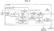
- FIG. 2 is a block diagram of the IP camera 2.
- the IP camera 2 includes an image sensor unit 21, an encoding unit 24, a measurement unit 22, a video delivery unit 25, and an alarm management unit 23.
- the image sensor unit 21 is a generally available camera module and includes an image pickup unit 211, an automatic gain control (AGC) unit 213, and an adjustment unit 214 to output digital data of the captured video-image.
- AGC automatic gain control
- the image pickup unit 211 is configured to photoelectrically convert light condensed by a lens unit 20 to output the converted electrical signal to the AGC unit 213 as a raw image format (RAW) signal 212.
- RAW raw image format
- the AGC unit 213 amplifies the RAW signal 212 to a predetermined level to output the amplified RAW signal to the adjustment unit 214.
- the image pickup unit 211 may be a complementary metal oxide semiconductor (CMOS) image sensor, and the AGC unit 213 may be provided in the image pickup unit 211 if the image pickup unit 211 outputs the analog-to-digital converted RAW signal.
- CMOS complementary metal oxide semiconductor
- the adjustment unit 214 is a central processing unit of the IP camera 2 which performs an image capturing control or an image processing such that the IP camera 2 outputs a desirable video-image.
- the adjustment unit 214 includes a lens control unit 215, a gradation correction unit 216, and a miscellaneous correction unit 218.
- the lens control unit 216 is configured to control the iris and focus of the lens unit 20 based on image data outputted from the AGC unit 213.
- a gradation correction (equalization) for the image data outputted from the AGC unit 213 is performed by the gradation correction unit 217.
- a color correction, an adaptive noise-filtering, a flicker removal, an edge enhancement and the like for the image data outputted from the AGC unit 213 are performed by the miscellaneous correction unit 218 to output the corrected image data as digital image data.
- the encoding unit 24 is configured to encode the digital image data outputted from the image sensor unit 21 to thereby generate encoded image data of a predetermined format such as joint photo graphic experts group (JPEG), H.264 or the like.
- JPEG joint photo graphic experts group
- the video delivery unit 25 is configured to deliver the encoded image data by using user datagram protocol/internet protocol (UDP/IP) or the like.
- UDP/IP user datagram protocol/internet protocol
- the measurement unit 22 is configured to detect a failure through a method which will be described later and output failure detection information 221 and 222 based on the digital image data 215 outputted from the image sensor unit 21.
- the measurement unit 22 includes a storage unit 28 which stores the digital image data 215 or values calculated from the digital image data 215.
- the failure detection information 221 is included in the encoded image data by the video delivery unit 25 and is delivered through a network 6.
- the failure detection information 222 is managed by the alarm management unit 23 and is sequentially outputted through the network 6 as an independent alarm notification 27.
- the failure detection information 221 is integrated into the encoded image data, so that the failure detection information 221 can be reliably delivered and recorded even with the conventional device.
- the failure detection information 222 there is an advantage that an alarm can be recognized at the receiving side without interpreting contents of the encoded image data. Therefore, in this example, the information is redundantly delivered.
- FIG. 3 shows a structure of encoded image data used in the monitoring system 1 of the present embodiment.
- Encoded image data 26 which is generally provided on a picture basis or the like, includes header information 301 and image data 302.
- the image data 302 is a bit stream generated by the encoding such as two-dimensional Huffman coding, context adaptive binary arithmetic coding (CABAC) or context adaptive variable length coding (CAVLC) in the encoding unit 24.
- CABAC context adaptive binary arithmetic coding
- CAVLC context adaptive variable length coding
- the header information 301 stores therein attributes (e.g., picture size and so on) of the image data in unit and parameters (e.g., quantum conversion table and so on) used in the encoding, and usually has a user data area 301 which can be arbitrarily used.
- video-image abnormality detection information 3012 is stored in the user data area 301.
- the failure detection information 221 may be an example of the video-image abnormality detection information 3012.
- the video-image abnormality detection information 3012 may include a presence or absence (or probability) of detection, a detection type, and detection area coordinates, which are provided to correspond to the number of the detection areas.
- FIG. 4 is a flowchart of algorithm A.
- Algorithm A is used for determining that an abnormality has occurred when there is a change in a mean value of a luminance signal within a measurement area.
- the measurement area and a set range (threshold) for determining the abnormality when there is a change in the mean value of the luminance signal are determined in advance to correspond to, e.g., those of the street lamp 12 which is expected to provide constant illuminance. For example, when the street lamp 12 is in a turn-on state in FIG. 1 , it is assumed that there is no luminance change in an image capturing area of the street lamp 12, so that it can be employed as the measurement area 606.
- the measurement unit 22 acquires the latest digital image data of one picture that is outputted from the image sensor unit 21 (step S401), and the process proceeds to step S402.
- step S402 a removal or a masking of the moving object in the measurement area is performed by using digital image data (background image) stored in the storage unit 28, and the process proceeds to step S403.
- digital image data background image
- the process for the corresponding picture may be aborted.
- the removal of the moving object can be performed by a well-known technique which is available in the art.
- step S403 the mean value of the luminance signal in the measurement area is calculated, and the process proceeds to step S404.
- step S404 the mean value of the luminance signal is converted into absolute illuminance and it is determined whether or not the mean value of the luminance signal is out of the set range. If it is determined that the mean value of the luminance signal is out of the set range (YES in step S404), then the process proceeds to step S405. If it is determined that the mean value of the luminance signal is within the set range (NO in step S404), then the process returns to step S401.
- the absolute illuminance in the measurement area is obtained by multiplying the mean value of the luminance signal by a coefficient determined by an AGC gain, an exposure time (shutter speed) and an aperture value (f-number).
- step S405 since the mean value of the luminance signal is out of the set range, it is determined that there is an abnormality in the digital image data 215 and the process returns back to step S401 after the failure detection information 221 is notified (outputted) to the video delivery unit 25 and the failure detection information 222 is notified (outputted) to the alarm management unit 23.
- the alarm management unit 23 Upon receiving the failure detection information 222, the alarm management unit 23 transmits an alarm to the server 3.
- the server 3 performs a process of, e.g., displaying a warning message upon receiving the alarm. Further, since the failure detection information 221 is recorded together with the video-image in the recording device 4, it becomes possible to check video-images before and after the video-image having the abnormality by searching information on the video-image abnormality in the recorded video-image.
- a measurement schedule is set to correspond to a time period during which the street lamp is turned on.
- the mean value of the luminance signal is preferably subjected to averaging even in the time domain as many as the number of pictures corresponding to a flickering cycle.
- the flickering cycle can be detected in the miscellaneous correction unit 218 or the like by techniques well known in the art.
- algorithm A it is possible to detect the covering of the lens unit 20 that is caused by, e.g., mischief or the like.
- FIG. 5 is a flowchart of algorithm B.
- Algorithm B is used for determining that an abnormality has occurred when there is no change in a mean value of a luminance signal within a measurement area.
- the imaging angle of view field of view
- the measurement area and a predetermined time period for determining the abnormality and a specific value for the amount of change in the mean value of the luminance signal are determined in advance so as to correspond to those for the object.
- the object includes an object that is illuminated by the light lamp (visible ray or near-infrared ray) equipped in the IP camera 2 or an external lighting device operated with the AC power supply frequency. Alternatively, the object may be the light lamp itself equipped in another IP camera 2.
- the measurement unit 22 acquires the latest digital image data of one picture that is outputted from the image sensor unit 21 (step S501), and the process proceeds to step S502.
- step S502 the mean value of the luminance signal in the measurement area is calculated, and the process proceeds to step S503.
- step S503 it is determined whether or not the amount of change in the mean value is smaller than or equal to the specific value by comparing a mean value of the luminance signal of the digital image data 215 with a mean value of the luminance signal of the previous digital image data stored in the storage unit 28. If the amount of change in the mean value is smaller than or equal to the specified value (YES in step S503), it is determined that there is a potential abnormality so that the process proceeds to step S504. If the amount of change in the mean value is greater than the specified value (NO in step S503), it is determined as normal so the process returns back to step S501.
- step S504 it is determined whether or not a state where there is no change in the mean value of the luminance signal (that is, the amount of change is smaller than or equal to the specific value) is maintained for the predetermined time period. If the no-change state is maintained for the predetermined time period (YES in step S504), it is determined as abnormal so that the process proceeds to step S505. If the no-change state is not maintained for the predetermined time period (NO in step S504), the process returns back to step S501.
- the predetermined time period is set based on the flickering period, a blinking pattern period of the lighting device itself, or a time period according to an error in the known change timing.
- step S505 it is determined that there is an abnormality in the digital image data 215 and the process returns back to step S501 after the failure detection information 221 is notified (outputted) to the video delivery unit 25 and the failure detection information 222 is notified (outputted) to the alarm management unit 23.
- the lighting device causing the flickering by using the variation of the lighting device causing the flickering, it is determined as abnormal when the flickering is no longer observed. Therefore, it is suitable for an indoor environment.
- the near-infrared lighting device equipped in the IP camera 2 or the like is controlled from the server 3 to be turned on, so that the operation of the failure detection can be continued.
- the algorithm B may be implemented only when the lighting device is turned on and off.
- the measurement area 607 which is specified as an area in which the luminance of the image is frequently changed (e.g., a hallway where there is a movement of the human being 11).
- the time period e.g., commuting time zone
- the human being passes by is used to set the measurement schedule.
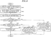
- FIGS. 7A to 7D are schematic views for explaining a principle of algorithm C and FIG. 8 is a flowchart of algorithm C.
- Algorithm C relates to a method for automatically setting the measurement area mentioned above. Specifically, in the method, an image frame (picture) is divided into a plurality of measurement areas, and areas suitable for the measurement areas 606 and 607 are specified by observing an aspect of the luminance change (a period or a width thereof) in a normal state.
- FIGS. 7A to 7D represent a change of the mean value of the luminance signal over time in each of the measurement areas 711 to 713, where a horizontal axis indicates time, and a vertical axis indicates the mean value of the luminance signal.
- the measurement unit 22 measures the change of the mean value of the luminance signal in each measurement area for a predetermined time period (e.g., one day) and stores the measurement result in the storage unit 28 (step S801).
- the plurality of the measurement areas are obtained by dividing the digital image data into N x M (e.g., 8 (rows) x 8 (columns)) areas as shown in FIG. 7A .
- the IP camera 2 itself sets the measurement period of, e.g., about one day after the installation thereof.
- step S802 the statistics of the mean value of the luminance signal are obtained for each measurement area.
- the statistics include a longest time period during which a state where there is no change in the mean value of the luminance signal is maintained, and the minimum and maximum values of the mean value of the luminance signal, and these statistics are stored in the storage unit 28 after the predetermined time period has lapsed.
- Steps S801 and S802 are generally performed in parallel.
- the longest time period can be obtained by a method in which the measurement unit 22 counts a time period for no change and resets the count value to zero when there is a change, and the measurement unit 22 overwrites the count value when the count value is greater than a previous count value stored in the storage unit 28.
- a previous reset time may be stored so that the previous reset time (the one before the current reset causing the overwriting) and the current reset time are also overwritten and stored. Further, 'the state where there is no change in the mean value of the luminance signal' may indicate that the change is less than 10% of the rating value.
- step S804 it is determined, for each measurement area, whether or not a level change constantly occurs in the mean value of the luminance signal. For a measurement area in which the level change constantly occurs (YES in step S804), a process in step S807 is performed. For a measurement area in which the level change does not constantly occur (NO in step S804), a process in step S805 is performed.
- a predetermined threshold it is determined that the level change constantly occurs in the mean value of the luminance signal.
- step S805 it is determined, for each measurement area, whether or not the level change hardly occurs in the mean value of the luminance signal. If it is determined that the level change hardly occurs (YES in step S805), then the process proceeds to step S808. If it is determined that the level change occurs but does not constantly occur (NO in step S805), then the process proceeds to step S806.
- a predetermined value i.e., close to 1
- step S806 the measurement area is not specified.
- the measurement area such as a measurement area 713 shown in FIG. 7A , which is subjected to step S806, indicates an area to which any one of algorithms A and B cannot be appropriately applied.
- step S807 the measurement area such as a measurement area 711 shown in FIG. 7A in which the level change constantly occurs in the mean value of the luminance signal becomes subjected to step S807.
- this measurement area is specified as an area to which algorithm B (a means for determining it as abnormal when there is no change in the mean value of the luminance signal) is to be applied.
- algorithm B a means for determining it as abnormal when there is no change in the mean value of the luminance signal
- the predetermined time period used in step S504 of algorithm B may be automatically set by adding a predetermined margin to the longest time period.
- the method for determining it as abnormal when there is no change in the mean value of the luminance signal is used to monitor this area.
- the graph 701 in FIG. 7B represents the above-described case.
- step S808 the measurement area such as a measurement area 712 shown in FIG. 7A in which the level change hardly occurs in the mean value of the luminance signal becomes subjected to step S808.
- this measurement area is specified as an area to which algorithm A (a means for determining it as abnormal when there is a change in the mean value of the luminance signal) is to be applied.
- algorithm A a means for determining it as abnormal when there is a change in the mean value of the luminance signal
- an upper limit and a lower limit of the set range used in step S404 of algorithm A may be automatically set by adding a predetermined margin to each of the minimum and maximum values. It is significant to set the maximum value since the abnormality due to, e.g., a deterioration of the image pickup unit may include a phenomenon such as white-black inversion in addition to a decrease in sensitivity.
- FIGS. 6A and 6B are a flowchart of algorithm D.
- Algorithm D is applied to determine the failure of the image sensor unit when there is no change in a video-image in which a moving object is removed after adjustments of an iris and a gain (exposure time and pixel gain) of the image sensor unit, which bring a change in the captured video-image.
- step S601 the measurement unit 22 acquires the latest digital image data of one picture that is outputted from the image sensor unit 21.
- step S602 similarly to step S402, an image with the moving object removed or masked is created from the acquired digital image data.
- step S603 the moving-object-removed image in step S602 is compared with a previous moving-object-removed image (fixedly stored or previously updated) in the storage unit 28, and if a difference therebetween does not exceed a threshold, then the process proceeds to step S601. If the difference therebetween exceeds the threshold, then the process proceeds to step S604.
- the difference can be calculated by the sum of absolute differences.
- the moving-object-removed image may be updated by, e.g., the weighted addition of two compared moving-object-removed images and stored in the storage unit 28.
- the update should not be carried out.
- step S603 is not essential, and step S602 and subsequent step S604 may be carried out periodically by the schedule specified in advance.
- step S604 for example, the iris of the image sensor unit 21 is adjusted and changed.
- This adjustment may be performed through the lens control unit 216 either by autonomously sensing a change in the digital image data or based on instructions from the measurement unit 22 to the lens control unit 216.
- the instructions from the measurement unit 22 may include an instruction to compensate the change in the video-image detected in step S603, a completely unrelated instruction (noise) and the like.
- the measurement unit 22 may be able to realize which direction a control amount has been changed with respect to which type of a lens unit 29.
- step S605 after the adjustment of the image sensor unit 21 is carried out, a moving-object-removed image is newly created by performing the same processing as steps S601 and S602, and the current moving-object-removed image is compared with the one before the current moving-object-removed image (e.g., the moving-object-removed image created in step S602).
- the photographing conditions since the photographing conditions are changed, it is a normal when there is a change.
- the process proceeds to step S610. Further, the update of the moving-object-removed image is not carried out after the adjustment of the image sensor unit 21 is carried out.
- step S606 the current moving-object-removed image in step S602 is compared with a previous moving-object-removed image stored before the adjustment of the image sensor unit 21 in the storage unit 28, and the process proceeds to step S601 when the difference therebetween does not exceed a predetermined threshold.
- the difference therebetween does not exceed a predetermined threshold indicates that the control amount with respect to the image sensor unit returns to its original level or is fixed to correspond to changes in the photographing environment.
- the difference in step S606 may be a difference after a high pass filtering (HPF) or an edge detection instead of a difference of the pixel value itself (SAD), or may be a difference obtained by performing such filtering process on a differential image which is not subjected to the sum of absolute differences.
- HPF high pass filtering
- SAD edge detection instead of a difference of the pixel value itself
- step S607 it is determined whether or not the adjustment of the image sensor unit has been performed a certain number of times or more.
- the process proceeds to step S604 when such adjustment is carried out less than the certain number of times.
- This provides a loop process that can exit to step S609 from step S606 in case where the sensor is normally operated.
- step S608 the control amount with respect to the image sensor unit 21 is changed for each adjustment, a random walk or an addition of a random walk to a change in a direction to reduce the difference with respect to the previous moving-object-removed image may be applied.
- step S608 when the image does not return to its original state after the change is recognized in step S603, it is determined that the angle of view is abnormal.
- the abnormality of the angle of view includes external factors such as a blindfold, lens damage, stoppages of some of lighting devices and the like other than a sensor issue such as a change of a video-image capturing direction.
- a partial failure of the sensor i.e., reading failure of some of the pixel values
- the abnormality detection information such as a detection type indicating a type of the abnormality of the angle of view is generated.
- the abnormality detection information such as a detection area (i.e., a region having a large number of pixels having values different from those in the previous moving-object-removed image) may also be generated.
- step S609 it is determined that the sensor has no problem.
- step S610 it is determined whether or not the proceeding from S605 to step S610 has occurred continuously a certain number of times or more (or it is determined whether or not the adjustment of the image sensor unit (step S604) has been performed a certain number of times or more). The process proceeds to step S604 when it does not reach the certain number of times.
- step S611 since the image does not change at all even though the image sensor unit is adjusted after the change is recognized in step S603, it is determined that there is a failure of the sensor:
- the failure of the sensor also includes an event that a video-image is suddenly frozen or blacked out in a large part of a frame and an event that a video-image is constantly and notably fluctuated on a pixel-by-pixel basis.
- the removal of the moving object is always employed in a large part of the frame to thereby replace the previous removal of the moving object, the process proceeds to step S611.
- abnormality detection information such as a detection type indicating the failure of the sensor is generated.
- step S611 it is determined that there is the failure of the sensor even when all of the lighting devices in the monitoring area are turned off due to a power failure or the like.
- step S612 the detection information (e.g., the failure detection information 221 and 222) obtained in step S608, step S609 or step S611 is transmitted to the alarm management unit 23 and the video delivery unit 25.
- the detection information e.g., the failure detection information 221 and 222
- step S613 alarms are aggregated in the server 3 which is capable of receiving the alarms from a plurality of the IP cameras 2 to be displayed on the display device 5. For example, if it can be estimated that an external or a single cause generates the multiple alarms at substantially the same time, the multiple alarms can be aggregated into a single alarm. For example, if sensor-failure alarms are simultaneously generated from a plurality of cameras, it is highly possible that lighting devices are turned off or a power failure occurs. Even in case where abnormalities in the angle of view are simultaneously generated, it can be estimated that environmental changes such as an earthquake or illuminance changes in a wide area over a plurality of the monitoring areas have occurred.
- alarms can be deleted instead of being displayed.
- alarms are generated from both of the measurement areas subjected to algorithms A and B at substantially the same time, it can be determined that it is highly possible that at least one of an abnormality in the angle of view and a sensor failure is generated in the corresponding single camera.
- the monitoring system of the present invention is capable of detecting video-image abnormalities of all of the camera devices even in large-scale monitoring systems.
- the present invention is described in detail above, the present invention is not limited to the monitoring system described above and may be widely applied to other monitoring systems.
Landscapes
- Engineering & Computer Science (AREA)
- Multimedia (AREA)
- Signal Processing (AREA)
- Physics & Mathematics (AREA)
- General Physics & Mathematics (AREA)
- Computer Vision & Pattern Recognition (AREA)
- Databases & Information Systems (AREA)
- Business, Economics & Management (AREA)
- Emergency Management (AREA)
- Computer Security & Cryptography (AREA)
- Health & Medical Sciences (AREA)
- Biomedical Technology (AREA)
- General Health & Medical Sciences (AREA)
- Studio Devices (AREA)
- Closed-Circuit Television Systems (AREA)
Abstract
Description
- The present invention relates to a monitoring system and a camera device.
- In some cases, a camera device used in a monitoring system may fail to capture a video-image due to changes in the photographing environment such as a camera failure or a lighting failure, camera tampering such as blocking or covering the lens of a camera, or the like.
- Conventionally, the camera device may automatically detect some failures, but cannot automatically detect all abnormalities in image data. As an example, in a case where a dark image is outputted from the camera device, it is difficult to distinguish whether a camera failure occurs or an image of a dark object is captured. Meanwhile, if there is an observer, the observer can comprehensively determine the presence or absence of abnormalities while estimating the cause of the abnormality by empirically understanding the photographing environment.
- In the related art, there is disclosed a solid-state pick-up device which is capable of detecting a failure, such as a case where no signal for the failure is outputted from an image sensor, even under the dark environment (see, e.g.,
Patent Document 1 or 2). - Patent Document 1: Japanese Patent Application Publication No.
2009-118427 - Patent Document 2: Japanese Patent Application Publication No.
2006-033385 - In a large-scale monitoring system, it is difficult for the observer to visually and immediately detect video-image abnormalities of all camera devices. Further, visual observation of the observer is not suitable practically for a small-scale monitoring system which is required to save manpower. In the case of a surveillance system for an unmanned store, a recorded video-image may be checked by the observer only when an incident has occurred without usually monitoring the store. In this case, video-image abnormalities may not be detected until the recorded video-image is visually checked at the time of the occurrence of the incident, which is problematic.
- However, a damage of the camera device or the like needs to be detected more reliably and more rapidly, as a potential threat to be monitored, by using other camera devices.
- In view of the above, the present invention aims to automatically detect an abnormality of image data caused by a failure of a camera device or the like by using a low-load video signal processing.
- According to one aspect of the present invention, there is provided a monitoring system which is conceptually configured to determine an abnormality by using an appropriate algorithm in which an object having a predetermined illuminance (luminance) is ensured in an imaging angle of view of the camera and it is determined whether or not incident light of the object can be retrieved while changing photographing conditions such as an aperture and an exposure time. More specifically, the monitoring system includes a plurality of camera devices and a server connected to the camera devices through a network. Each of the camera devices includes an image sensor unit and a measurement unit, and the measurement unit is configured to divide image data acquired by the image sensor unit into a plurality of areas, and detect a video-image abnormality from a mean value of a luminance signal and a change in the mean value of the luminance signal in each of the areas. Further, each of the camera devices is configured to transmit detection information of the video-image abnormality to the server when the measurement unit detects the video-image abnormality.
- Further, according to another aspect of the present invention, there is provided a camera device including an image sensor unit and a measurement unit. The measurement unit is configured to divide image data acquired by the image sensor unit into a plurality of areas, and detect a video-image abnormality from a mean value of a luminance signal and a change in the mean value of the luminance signal in each of the areas.
- Further, a camera device according to still another aspect of the present invention is the camera device described above, and the measurement unit detects the video-image abnormality after removing a moving object in a measurement area from the image data acquired by the image sensor unit.
- According to the present invention, it is possible to efficiently detect video-image abnormalities from a plurality of camera devices without an observer's visual observation.
-
-
FIG. 1 shows a schematic configuration of amonitoring system 1 according to one embodiment of the present invention. -
FIG. 2 is a block diagram of anIP camera 2 included in themonitoring system 1. -
FIG. 3 shows a structure of encoded image data used in themonitoring system 1. -
FIG. 4 is a flowchart of algorithm A for a failure detection of ameasurement unit 22. -
FIG. 5 is a flowchart of algorithm B for the failure detection of themeasurement unit 22. -
FIGS. 6A and6B are a flowchart of algorithm D for the failure detection of themeasurement unit 22. -
FIGS. 7A to 7D are schematic views for explaining a principle of algorithm C in themeasurement unit 22. -
FIG. 8 is a flowchart of algorithm C for the failure detection of themeasurement unit 22. -
FIG. 1 shows a schematic configuration of a monitoring system according to one embodiment of the present invention. - A
monitoring system 1 is configured such that a plurality of internet protocol (IP) cameras (network cameras) 2 are connected to aserver 3 and arecording device 4 through anetwork 6. - Each
IP camera 2 is fixedly installed to capture a video-image in amonitoring area 10. Specifically, theIP camera 2 captures a moving object such as ahuman being 11 and a stationary object such as astreet lamp 12, for example. - A
server 3 transmits, for example, an instruction of video-image delivery to theIP camera 2 to display an alarm and/or the video-image received from theIP camera 2 on adisplay device 5 connected to theserver 3. In addition, theserver 3 performs monitoring of an operation of theIP camera 2, remote controlling of the light lamp built in theIP camera 2, integration of received alarms and the like. Further, theserver 3 provides ascreen 604 for setting a plurality of measurement areas 606 and 607 which will be described later by a manipulation of the user. - The
recording device 4 includes a large-capacity storage medium such as a hard disk drive (HDD) and is configured to record video data delivered from theIP camera 2 at all times or in response to the alarm. Further, in response to a request from theserver 3, therecording device 4 reads out the recorded video data to transmit it to theserver 3. - The
display device 5 is a general computer display.FIG. 1 shows a state in which thedisplay device 5 displays the measurementarea setting screen 604. In the measurementarea setting screen 604, the measurement areas 606 and 607 which are arbitrarily set by the user are displayed as rectangles. -
FIG. 2 is a block diagram of theIP camera 2. - The
IP camera 2 includes animage sensor unit 21, anencoding unit 24, ameasurement unit 22, avideo delivery unit 25, and analarm management unit 23. - The
image sensor unit 21 is a generally available camera module and includes animage pickup unit 211, an automatic gain control (AGC)unit 213, and anadjustment unit 214 to output digital data of the captured video-image. - The
image pickup unit 211 is configured to photoelectrically convert light condensed by alens unit 20 to output the converted electrical signal to theAGC unit 213 as a raw image format (RAW)signal 212. - The
AGC unit 213 amplifies the RAWsignal 212 to a predetermined level to output the amplified RAW signal to theadjustment unit 214. Theimage pickup unit 211 may be a complementary metal oxide semiconductor (CMOS) image sensor, and theAGC unit 213 may be provided in theimage pickup unit 211 if theimage pickup unit 211 outputs the analog-to-digital converted RAW signal. - The
adjustment unit 214 is a central processing unit of theIP camera 2 which performs an image capturing control or an image processing such that theIP camera 2 outputs a desirable video-image. Theadjustment unit 214 includes alens control unit 215, agradation correction unit 216, and amiscellaneous correction unit 218. - The
lens control unit 216 is configured to control the iris and focus of thelens unit 20 based on image data outputted from theAGC unit 213. - A gradation correction (equalization) for the image data outputted from the
AGC unit 213 is performed by thegradation correction unit 217. A color correction, an adaptive noise-filtering, a flicker removal, an edge enhancement and the like for the image data outputted from theAGC unit 213 are performed by themiscellaneous correction unit 218 to output the corrected image data as digital image data. - The
encoding unit 24 is configured to encode the digital image data outputted from theimage sensor unit 21 to thereby generate encoded image data of a predetermined format such as joint photo graphic experts group (JPEG), H.264 or the like. - The
video delivery unit 25 is configured to deliver the encoded image data by using user datagram protocol/internet protocol (UDP/IP) or the like. - The
measurement unit 22 is configured to detect a failure through a method which will be described later and outputfailure detection information digital image data 215 outputted from theimage sensor unit 21. Themeasurement unit 22 includes astorage unit 28 which stores thedigital image data 215 or values calculated from thedigital image data 215. - The
failure detection information 221 is included in the encoded image data by thevideo delivery unit 25 and is delivered through anetwork 6. - The
failure detection information 222 is managed by thealarm management unit 23 and is sequentially outputted through thenetwork 6 as anindependent alarm notification 27. - With regard to the
failure detection information 221, thefailure detection information 221 is integrated into the encoded image data, so that thefailure detection information 221 can be reliably delivered and recorded even with the conventional device. With regard to thefailure detection information 222, there is an advantage that an alarm can be recognized at the receiving side without interpreting contents of the encoded image data. Therefore, in this example, the information is redundantly delivered. -
FIG. 3 shows a structure of encoded image data used in themonitoring system 1 of the present embodiment. - Encoded
image data 26, which is generally provided on a picture basis or the like, includesheader information 301 andimage data 302. - The
image data 302 is a bit stream generated by the encoding such as two-dimensional Huffman coding, context adaptive binary arithmetic coding (CABAC) or context adaptive variable length coding (CAVLC) in theencoding unit 24. - The
header information 301 stores therein attributes (e.g., picture size and so on) of the image data in unit and parameters (e.g., quantum conversion table and so on) used in the encoding, and usually has auser data area 301 which can be arbitrarily used. In this example, video-imageabnormality detection information 3012 is stored in theuser data area 301. - The
failure detection information 221 may be an example of the video-imageabnormality detection information 3012. The video-imageabnormality detection information 3012 may include a presence or absence (or probability) of detection, a detection type, and detection area coordinates, which are provided to correspond to the number of the detection areas. - Hereinafter, there will be described several algorithms of the failure detection by the
measurement unit 22. These algorithms may be implemented alone or in combination. In the latter case, the algorithms may be implemented in parallel. Alternatively, one algorithm may be dependent on another algorithm such that upon detecting a failure by executing one algorithm, another algorithm is executed so as to double-check the detection result. -
FIG. 4 is a flowchart of algorithm A. Algorithm A is used for determining that an abnormality has occurred when there is a change in a mean value of a luminance signal within a measurement area. The measurement area and a set range (threshold) for determining the abnormality when there is a change in the mean value of the luminance signal are determined in advance to correspond to, e.g., those of thestreet lamp 12 which is expected to provide constant illuminance. For example, when thestreet lamp 12 is in a turn-on state inFIG. 1 , it is assumed that there is no luminance change in an image capturing area of thestreet lamp 12, so that it can be employed as the measurement area 606. - The
measurement unit 22 acquires the latest digital image data of one picture that is outputted from the image sensor unit 21 (step S401), and the process proceeds to step S402. - In step S402, a removal or a masking of the moving object in the measurement area is performed by using digital image data (background image) stored in the
storage unit 28, and the process proceeds to step S403. Alternatively, when the moving object is detected in the measurement area, the process for the corresponding picture may be aborted. The removal of the moving object can be performed by a well-known technique which is available in the art. - In step S403, the mean value of the luminance signal in the measurement area is calculated, and the process proceeds to step S404.
- In step S404, the mean value of the luminance signal is converted into absolute illuminance and it is determined whether or not the mean value of the luminance signal is out of the set range. If it is determined that the mean value of the luminance signal is out of the set range (YES in step S404), then the process proceeds to step S405. If it is determined that the mean value of the luminance signal is within the set range (NO in step S404), then the process returns to step S401. The absolute illuminance in the measurement area is obtained by multiplying the mean value of the luminance signal by a coefficient determined by an AGC gain, an exposure time (shutter speed) and an aperture value (f-number).
- In step S405, since the mean value of the luminance signal is out of the set range, it is determined that there is an abnormality in the
digital image data 215 and the process returns back to step S401 after thefailure detection information 221 is notified (outputted) to thevideo delivery unit 25 and thefailure detection information 222 is notified (outputted) to thealarm management unit 23. - Upon receiving the
failure detection information 222, thealarm management unit 23 transmits an alarm to theserver 3. Theserver 3 performs a process of, e.g., displaying a warning message upon receiving the alarm. Further, since thefailure detection information 221 is recorded together with the video-image in therecording device 4, it becomes possible to check video-images before and after the video-image having the abnormality by searching information on the video-image abnormality in the recorded video-image. - In algorithm A, since an accurate operation can be performed only when the
street lamp 12 is in a turn-on state, a measurement schedule is set to correspond to a time period during which the street lamp is turned on. Meanwhile, in a case where thestreet lamp 12 is a lighting device which may cause a flickering, the mean value of the luminance signal is preferably subjected to averaging even in the time domain as many as the number of pictures corresponding to a flickering cycle. The flickering cycle can be detected in themiscellaneous correction unit 218 or the like by techniques well known in the art. - According to algorithm A, it is possible to detect the covering of the
lens unit 20 that is caused by, e.g., mischief or the like. -
FIG. 5 is a flowchart of algorithm B. Algorithm B is used for determining that an abnormality has occurred when there is no change in a mean value of a luminance signal within a measurement area. In this example, in the imaging angle of view (field of view), there is an object with illuminance (luminance) being changed (blinking) at a known timing. The measurement area and a predetermined time period for determining the abnormality and a specific value for the amount of change in the mean value of the luminance signal are determined in advance so as to correspond to those for the object. The object includes an object that is illuminated by the light lamp (visible ray or near-infrared ray) equipped in theIP camera 2 or an external lighting device operated with the AC power supply frequency. Alternatively, the object may be the light lamp itself equipped in anotherIP camera 2. - The
measurement unit 22 acquires the latest digital image data of one picture that is outputted from the image sensor unit 21 (step S501), and the process proceeds to step S502. - In step S502, the mean value of the luminance signal in the measurement area is calculated, and the process proceeds to step S503.
- In step S503, it is determined whether or not the amount of change in the mean value is smaller than or equal to the specific value by comparing a mean value of the luminance signal of the
digital image data 215 with a mean value of the luminance signal of the previous digital image data stored in thestorage unit 28. If the amount of change in the mean value is smaller than or equal to the specified value (YES in step S503), it is determined that there is a potential abnormality so that the process proceeds to step S504. If the amount of change in the mean value is greater than the specified value (NO in step S503), it is determined as normal so the process returns back to step S501. - In step S504, it is determined whether or not a state where there is no change in the mean value of the luminance signal (that is, the amount of change is smaller than or equal to the specific value) is maintained for the predetermined time period. If the no-change state is maintained for the predetermined time period (YES in step S504), it is determined as abnormal so that the process proceeds to step S505. If the no-change state is not maintained for the predetermined time period (NO in step S504), the process returns back to step S501. The predetermined time period is set based on the flickering period, a blinking pattern period of the lighting device itself, or a time period according to an error in the known change timing.
- In step S505, it is determined that there is an abnormality in the
digital image data 215 and the process returns back to step S501 after thefailure detection information 221 is notified (outputted) to thevideo delivery unit 25 and thefailure detection information 222 is notified (outputted) to thealarm management unit 23. - In this example, by using the variation of the lighting device causing the flickering, it is determined as abnormal when the flickering is no longer observed. Therefore, it is suitable for an indoor environment. When no human being is present so that the lighting device is turned off, the near-infrared lighting device equipped in the
IP camera 2 or the like is controlled from theserver 3 to be turned on, so that the operation of the failure detection can be continued. Alternatively, if it is preferable to optionally perform the failure detection, the algorithm B may be implemented only when the lighting device is turned on and off. - Alternatively, it is preferable to use the measurement area 607, which is specified as an area in which the luminance of the image is frequently changed (e.g., a hallway where there is a movement of the human being 11). In this case, the time period (e.g., commuting time zone) during which the human being passes by is used to set the measurement schedule.
-
FIGS. 7A to 7D are schematic views for explaining a principle of algorithm C andFIG. 8 is a flowchart of algorithm C. Algorithm C relates to a method for automatically setting the measurement area mentioned above. Specifically, in the method, an image frame (picture) is divided into a plurality of measurement areas, and areas suitable for the measurement areas 606 and 607 are specified by observing an aspect of the luminance change (a period or a width thereof) in a normal state. - Graphs shown in
FIGS. 7A to 7D represent a change of the mean value of the luminance signal over time in each of themeasurement areas 711 to 713, where a horizontal axis indicates time, and a vertical axis indicates the mean value of the luminance signal. - As shown in
FIG. 8 , themeasurement unit 22 measures the change of the mean value of the luminance signal in each measurement area for a predetermined time period (e.g., one day) and stores the measurement result in the storage unit 28 (step S801). The plurality of the measurement areas are obtained by dividing the digital image data into N x M (e.g., 8 (rows) x 8 (columns)) areas as shown inFIG. 7A . TheIP camera 2 itself sets the measurement period of, e.g., about one day after the installation thereof. - In step S802, the statistics of the mean value of the luminance signal are obtained for each measurement area. The statistics include a longest time period during which a state where there is no change in the mean value of the luminance signal is maintained, and the minimum and maximum values of the mean value of the luminance signal, and these statistics are stored in the
storage unit 28 after the predetermined time period has lapsed. Steps S801 and S802 are generally performed in parallel. For example, the longest time period can be obtained by a method in which themeasurement unit 22 counts a time period for no change and resets the count value to zero when there is a change, and themeasurement unit 22 overwrites the count value when the count value is greater than a previous count value stored in thestorage unit 28. Preferably, when the overwriting is carried out, a previous reset time may be stored so that the previous reset time (the one before the current reset causing the overwriting) and the current reset time are also overwritten and stored. Further, 'the state where there is no change in the mean value of the luminance signal' may indicate that the change is less than 10% of the rating value. - In step S804, it is determined, for each measurement area, whether or not a level change constantly occurs in the mean value of the luminance signal. For a measurement area in which the level change constantly occurs (YES in step S804), a process in step S807 is performed. For a measurement area in which the level change does not constantly occur (NO in step S804), a process in step S805 is performed. Here, when the longest time period obtained in step S802 is equal to or less than a predetermined threshold, it is determined that the level change constantly occurs in the mean value of the luminance signal.
- In step S805, it is determined, for each measurement area, whether or not the level change hardly occurs in the mean value of the luminance signal. If it is determined that the level change hardly occurs (YES in step S805), then the process proceeds to step S808. If it is determined that the level change occurs but does not constantly occur (NO in step S805), then the process proceeds to step S806. Here, when the ratio of the maximum value and the minimum value obtained in step S802 is equal to or smaller than a predetermined value (i.e., close to 1), it is determined that the level change hardly occurs in the mean value of the luminance signal.
- In step S806, the measurement area is not specified. The measurement area such as a
measurement area 713 shown inFIG. 7A , which is subjected to step S806, indicates an area to which any one of algorithms A and B cannot be appropriately applied. - In step S807, the measurement area such as a
measurement area 711 shown inFIG. 7A in which the level change constantly occurs in the mean value of the luminance signal becomes subjected to step S807. Thus, this measurement area is specified as an area to which algorithm B (a means for determining it as abnormal when there is no change in the mean value of the luminance signal) is to be applied. At this time, since the longest time period during which there is no change in the mean value of the luminance signal is known for this measurement area, the predetermined time period used in step S504 of algorithm B may be automatically set by adding a predetermined margin to the longest time period. For example, if it can be known that there is an area in which there is no change in the mean value of the luminance signal for 5 minutes in maximum or less (that is, there is a movement within 5 minutes), the method for determining it as abnormal when there is no change in the mean value of the luminance signal is used to monitor this area. Thegraph 701 inFIG. 7B represents the above-described case. - In step S808, the measurement area such as a measurement area 712 shown in
FIG. 7A in which the level change hardly occurs in the mean value of the luminance signal becomes subjected to step S808. Thus, this measurement area is specified as an area to which algorithm A (a means for determining it as abnormal when there is a change in the mean value of the luminance signal) is to be applied. At this time, since the minimum and maximum values of the mean value of the luminance signal are known for this measurement area, an upper limit and a lower limit of the set range used in step S404 of algorithm A may be automatically set by adding a predetermined margin to each of the minimum and maximum values. It is significant to set the maximum value since the abnormality due to, e.g., a deterioration of the image pickup unit may include a phenomenon such as white-black inversion in addition to a decrease in sensitivity. -
FIGS. 6A and6B are a flowchart of algorithm D. Algorithm D is applied to determine the failure of the image sensor unit when there is no change in a video-image in which a moving object is removed after adjustments of an iris and a gain (exposure time and pixel gain) of the image sensor unit, which bring a change in the captured video-image. - In step S601, the
measurement unit 22 acquires the latest digital image data of one picture that is outputted from theimage sensor unit 21. - Next, in step S602, similarly to step S402, an image with the moving object removed or masked is created from the acquired digital image data.
- Next, in step S603, the moving-object-removed image in step S602 is compared with a previous moving-object-removed image (fixedly stored or previously updated) in the
storage unit 28, and if a difference therebetween does not exceed a threshold, then the process proceeds to step S601. If the difference therebetween exceeds the threshold, then the process proceeds to step S604. Here, the difference can be calculated by the sum of absolute differences. Moreover, the moving-object-removed image may be updated by, e.g., the weighted addition of two compared moving-object-removed images and stored in thestorage unit 28. However, when it is intended to detect the decrease in sensitivity due to the aging deterioration in step S603, the update should not be carried out. - Further, the processing of step S603 is not essential, and step S602 and subsequent step S604 may be carried out periodically by the schedule specified in advance.
- In step S604, for example, the iris of the
image sensor unit 21 is adjusted and changed. This adjustment may be performed through thelens control unit 216 either by autonomously sensing a change in the digital image data or based on instructions from themeasurement unit 22 to thelens control unit 216. The instructions from themeasurement unit 22 may include an instruction to compensate the change in the video-image detected in step S603, a completely unrelated instruction (noise) and the like. Although it is not essential, themeasurement unit 22 may be able to realize which direction a control amount has been changed with respect to which type of a lens unit 29. - Next, in step S605, after the adjustment of the
image sensor unit 21 is carried out, a moving-object-removed image is newly created by performing the same processing as steps S601 and S602, and the current moving-object-removed image is compared with the one before the current moving-object-removed image (e.g., the moving-object-removed image created in step S602). Here, since the photographing conditions are changed, it is a normal when there is a change. When there is no change, the process proceeds to step S610. Further, the update of the moving-object-removed image is not carried out after the adjustment of theimage sensor unit 21 is carried out. - In step S606, the current moving-object-removed image in step S602 is compared with a previous moving-object-removed image stored before the adjustment of the
image sensor unit 21 in thestorage unit 28, and the process proceeds to step S601 when the difference therebetween does not exceed a predetermined threshold. Here, "the difference therebetween does not exceed a predetermined threshold" indicates that the control amount with respect to the image sensor unit returns to its original level or is fixed to correspond to changes in the photographing environment. The difference in step S606 may be a difference after a high pass filtering (HPF) or an edge detection instead of a difference of the pixel value itself (SAD), or may be a difference obtained by performing such filtering process on a differential image which is not subjected to the sum of absolute differences. - Next, in step S607, it is determined whether or not the adjustment of the image sensor unit has been performed a certain number of times or more. The process proceeds to step S604 when such adjustment is carried out less than the certain number of times. This provides a loop process that can exit to step S609 from step S606 in case where the sensor is normally operated. When such adjustment is carried out the certain number of times, the process proceeds to step S608. Although the control amount with respect to the
image sensor unit 21 is changed for each adjustment, a random walk or an addition of a random walk to a change in a direction to reduce the difference with respect to the previous moving-object-removed image may be applied. Moreover, there is some delay after the control amount with respect to theimage sensor unit 21 is changed until the image data based thereon is obtained. It is preferable that the time required to perform the certain number of adjustments is set to be sufficiently longer than the delay. - In step S608, when the image does not return to its original state after the change is recognized in step S603, it is determined that the angle of view is abnormal. Here, the abnormality of the angle of view includes external factors such as a blindfold, lens damage, stoppages of some of lighting devices and the like other than a sensor issue such as a change of a video-image capturing direction. In this case, it is highly possible that the sensor is not completely failed and is in operation to capture an image of something. However, a partial failure of the sensor (i.e., reading failure of some of the pixel values) can be included in the abnormality of the angle of view. Then, abnormality detection information such as a detection type indicating a type of the abnormality of the angle of view is generated. Further, if necessary, the abnormality detection information such as a detection area (i.e., a region having a large number of pixels having values different from those in the previous moving-object-removed image) may also be generated.
- In step S609, it is determined that the sensor has no problem.
- In step S610, it is determined whether or not the proceeding from S605 to step S610 has occurred continuously a certain number of times or more (or it is determined whether or not the adjustment of the image sensor unit (step S604) has been performed a certain number of times or more). The process proceeds to step S604 when it does not reach the certain number of times.
- In step S611, since the image does not change at all even though the image sensor unit is adjusted after the change is recognized in step S603, it is determined that there is a failure of the sensor: Here, the failure of the sensor also includes an event that a video-image is suddenly frozen or blacked out in a large part of a frame and an event that a video-image is constantly and terribly fluctuated on a pixel-by-pixel basis. In such video-image, the removal of the moving object is always employed in a large part of the frame to thereby replace the previous removal of the moving object, the process proceeds to step S611. Then, abnormality detection information such as a detection type indicating the failure of the sensor is generated. Further, in step S611, it is determined that there is the failure of the sensor even when all of the lighting devices in the monitoring area are turned off due to a power failure or the like.
- In step S612, the detection information (e.g., the
failure detection information 221 and 222) obtained in step S608, step S609 or step S611 is transmitted to thealarm management unit 23 and thevideo delivery unit 25. - In step S613, alarms are aggregated in the
server 3 which is capable of receiving the alarms from a plurality of theIP cameras 2 to be displayed on thedisplay device 5. For example, if it can be estimated that an external or a single cause generates the multiple alarms at substantially the same time, the multiple alarms can be aggregated into a single alarm. For example, if sensor-failure alarms are simultaneously generated from a plurality of cameras, it is highly possible that lighting devices are turned off or a power failure occurs. Even in case where abnormalities in the angle of view are simultaneously generated, it can be estimated that environmental changes such as an earthquake or illuminance changes in a wide area over a plurality of the monitoring areas have occurred. If it has been experienced and studied that such events are generated frequently or at a fixed time, such alarms can be deleted instead of being displayed. In addition, in a single camera, if alarms are generated from both of the measurement areas subjected to algorithms A and B at substantially the same time, it can be determined that it is highly possible that at least one of an abnormality in the angle of view and a sensor failure is generated in the corresponding single camera. - According to the embodiments described above, the monitoring system of the present invention is capable of detecting video-image abnormalities of all of the camera devices even in large-scale monitoring systems.
- Although the present invention is described in detail above, the present invention is not limited to the monitoring system described above and may be widely applied to other monitoring systems.
Claims (3)
- A monitoring system comprising:a plurality of camera devices; anda server connected to the camera devices through a network,wherein each of the camera devices includes an image sensor unit and a measurement unit,wherein the measurement unit is configured to divide image data acquired by the image sensor unit into a plurality of areas, and detect a video-image abnormality from a mean value of a luminance signal and a change in the mean value of the luminance signal in each of the areas, andwherein each of the camera devices is configured to transmit detection information of the video-image abnormality to the server when the measurement unit detects the video-image abnormality.
- A camera device comprising:an image sensor unit; anda measurement unit,wherein the measurement unit is configured to divide image data acquired by the image sensor unit into a plurality of areas, and detect a video-image abnormality from a mean value of a luminance signal and a change in the mean value of the luminance signal in each of the areas.
- The camera device of claim 2, wherein the measurement unit detects the video-image abnormality after removing a moving object in a measurement area from the image data acquired by the image sensor unit.
Applications Claiming Priority (2)
| Application Number | Priority Date | Filing Date | Title |
|---|---|---|---|
| JP2014112890 | 2014-05-30 | ||
| PCT/JP2015/065580 WO2015182751A1 (en) | 2014-05-30 | 2015-05-29 | Monitoring system and camera device |
Publications (3)
| Publication Number | Publication Date |
|---|---|
| EP3151552A1 true EP3151552A1 (en) | 2017-04-05 |
| EP3151552A4 EP3151552A4 (en) | 2018-02-21 |
| EP3151552B1 EP3151552B1 (en) | 2024-10-30 |
Family
ID=54699071
Family Applications (1)
| Application Number | Title | Priority Date | Filing Date |
|---|---|---|---|
| EP15800542.1A Active EP3151552B1 (en) | 2014-05-30 | 2015-05-29 | Monitoring system and camera device |
Country Status (4)
| Country | Link |
|---|---|
| US (1) | US10277805B2 (en) |
| EP (1) | EP3151552B1 (en) |
| JP (1) | JP6395823B2 (en) |
| WO (1) | WO2015182751A1 (en) |
Cited By (1)
| Publication number | Priority date | Publication date | Assignee | Title |
|---|---|---|---|---|
| CN110324610A (en) * | 2018-03-30 | 2019-10-11 | 浙江宇视科技有限公司 | The maintaining method and device of IPC equipment |
Families Citing this family (24)
| Publication number | Priority date | Publication date | Assignee | Title |
|---|---|---|---|---|
| US10404949B2 (en) * | 2016-07-11 | 2019-09-03 | The Boeing Company | Secure aircraft camera monitoring system |
| CN113271400B (en) | 2016-09-16 | 2023-12-19 | 索尼半导体解决方案公司 | Imaging device and electronic equipment |
| JP2018082233A (en) * | 2016-11-14 | 2018-05-24 | ソニー株式会社 | Monitoring system, monitoring sensor device, monitoring method, and program |
| KR102617992B1 (en) * | 2016-12-27 | 2023-12-26 | 한화비전 주식회사 | Predictive diagnosis apparatus and surveillance system |
| JP6392908B2 (en) * | 2017-01-12 | 2018-09-19 | ファナック株式会社 | Visual sensor abnormality cause estimation system |
| WO2018180200A1 (en) * | 2017-03-28 | 2018-10-04 | 株式会社日立国際電気 | Monitoring system and monitoring method |
| JP6993655B2 (en) * | 2017-10-16 | 2022-01-13 | Necプラットフォームズ株式会社 | Communication control methods, communication control devices, and communication control programs for network camera systems, including network cameras. |
| KR102424519B1 (en) * | 2018-01-04 | 2022-07-26 | 삼성전자 주식회사 | Display apparatus and control method thereof |
| US20190373165A1 (en) * | 2018-05-09 | 2019-12-05 | Wizr Llc | Learning to switch, tune, and retrain ai models |
| JP2020060531A (en) * | 2018-10-12 | 2020-04-16 | 株式会社デンソーテン | Abnormal detector, abnormality detection system, and method for detecting abnormality |
| CN111510669B (en) * | 2019-01-30 | 2024-07-30 | 拉碧斯半导体株式会社 | Video signal processing device, video freeze detection circuit, and video freeze detection method |
| JP7247760B2 (en) | 2019-06-03 | 2023-03-29 | 株式会社デンソー | Sticking determination device and sticking determination method |
| CN112422949A (en) * | 2019-08-22 | 2021-02-26 | 北京奇虎科技有限公司 | Method and device for detecting visual angle change of camera |
| US11653120B2 (en) | 2019-08-28 | 2023-05-16 | Sony Interactive Entertainment Inc. | Sensor system, image processing apparatus, image processing method, and program |
| US11653109B2 (en) * | 2019-08-28 | 2023-05-16 | Sony Interactive Entertainment Inc. | Sensor system, image processing apparatus, image processing method, and program |
| CN111770309B (en) * | 2020-06-24 | 2022-03-18 | 浙江大华技术股份有限公司 | Video uploading method and device, electronic equipment and storage medium |
| CN112911274B (en) * | 2020-11-17 | 2021-12-17 | 江苏中科能凯夫空调有限公司 | Self-adaptive monitoring video detection platform and method |
| JP2023019086A (en) * | 2021-07-28 | 2023-02-09 | キヤノン株式会社 | Transmission control device, transmission control device operation method, and program |
| JP2023035448A (en) * | 2021-09-01 | 2023-03-13 | パナソニックIpマネジメント株式会社 | Surveillance device, surveillance system, and surveillance method |
| JP7815001B2 (en) * | 2022-03-24 | 2026-02-17 | 富士フイルム株式会社 | Medical image processing system and method of operation |
| JP2023144519A (en) * | 2022-03-28 | 2023-10-11 | ラピステクノロジー株式会社 | Video signal processing device |
| JP2023157347A (en) * | 2022-04-14 | 2023-10-26 | キヤノン株式会社 | Image processing device, control method for image processing device, program, and image processing system |
| CN114513656A (en) * | 2022-04-18 | 2022-05-17 | 武汉中科通达高新技术股份有限公司 | Automatic testing method and device for video platform, electronic equipment and storage medium |
| WO2026052447A1 (en) * | 2024-09-04 | 2026-03-12 | Signify Holding B.V. | Method and system for object detection assessment |
Family Cites Families (18)
| Publication number | Priority date | Publication date | Assignee | Title |
|---|---|---|---|---|
| JP3113259B2 (en) * | 1989-07-18 | 2000-11-27 | 富士写真フイルム株式会社 | Exposure control method and apparatus for video camera |
| JP3677192B2 (en) * | 2000-04-19 | 2005-07-27 | シャープ株式会社 | Image processing device |
| WO2002021441A1 (en) * | 2000-09-06 | 2002-03-14 | Hitachi, Ltd. | Abnormal behavior detector |
| JP2005354278A (en) * | 2004-06-09 | 2005-12-22 | Seiko Epson Corp | Image data processing for processing image data of an image captured by an imaging means |
| JP2006033385A (en) | 2004-07-15 | 2006-02-02 | Canon Inc | Imaging device |
| US8724891B2 (en) * | 2004-08-31 | 2014-05-13 | Ramot At Tel-Aviv University Ltd. | Apparatus and methods for the detection of abnormal motion in a video stream |
| JP4611899B2 (en) * | 2006-01-12 | 2011-01-12 | アルパイン株式会社 | Camera lens dirt detection device and image display system |
| JP2009118427A (en) | 2007-11-09 | 2009-05-28 | Panasonic Corp | Solid-state imaging device and driving method thereof |
| JP5405366B2 (en) * | 2010-03-18 | 2014-02-05 | セコム株式会社 | Image monitoring apparatus and monitoring system |
| JP5400718B2 (en) * | 2010-07-12 | 2014-01-29 | 株式会社日立国際電気 | Monitoring system and monitoring method |
| JP5087112B2 (en) * | 2010-07-22 | 2012-11-28 | アイテック阪急阪神株式会社 | Self-monitoring camera device |
| JP5241782B2 (en) | 2010-07-30 | 2013-07-17 | 株式会社日立製作所 | Surveillance camera system having a camera abnormality detection device |
| JP2012138768A (en) | 2010-12-27 | 2012-07-19 | Hitachi Kokusai Electric Inc | Dome type monitor camera system |
| JP2012170011A (en) * | 2011-02-16 | 2012-09-06 | Canon Inc | Imaging apparatus, imaging method, and program |
| JP2013041400A (en) * | 2011-08-15 | 2013-02-28 | Sony Corp | Image processing device, image processing method and program |
| JP2014022801A (en) * | 2012-07-13 | 2014-02-03 | Sony Corp | Image processing apparatus, information processing method, information processing program |
| JP6270433B2 (en) * | 2013-11-26 | 2018-01-31 | キヤノン株式会社 | Information processing apparatus, information processing method, and information processing system |
| JP6299299B2 (en) * | 2014-03-14 | 2018-03-28 | オムロン株式会社 | Event detection apparatus and event detection method |
-
2015
- 2015-05-29 US US15/314,663 patent/US10277805B2/en active Active
- 2015-05-29 EP EP15800542.1A patent/EP3151552B1/en active Active
- 2015-05-29 WO PCT/JP2015/065580 patent/WO2015182751A1/en not_active Ceased
- 2015-05-29 JP JP2016523579A patent/JP6395823B2/en active Active
Cited By (2)
| Publication number | Priority date | Publication date | Assignee | Title |
|---|---|---|---|---|
| CN110324610A (en) * | 2018-03-30 | 2019-10-11 | 浙江宇视科技有限公司 | The maintaining method and device of IPC equipment |
| CN110324610B (en) * | 2018-03-30 | 2020-10-20 | 浙江宇视科技有限公司 | Maintenance method and device for IPC equipment |
Also Published As
| Publication number | Publication date |
|---|---|
| US20170195556A1 (en) | 2017-07-06 |
| JP6395823B2 (en) | 2018-09-26 |
| JPWO2015182751A1 (en) | 2017-04-20 |
| WO2015182751A1 (en) | 2015-12-03 |
| US10277805B2 (en) | 2019-04-30 |
| EP3151552A4 (en) | 2018-02-21 |
| EP3151552B1 (en) | 2024-10-30 |
Similar Documents
| Publication | Publication Date | Title |
|---|---|---|
| EP3151552B1 (en) | Monitoring system and camera device | |
| JP7207793B2 (en) | Video-based real-time intrusion detection method and surveillance camera using artificial intelligence | |
| US9497425B2 (en) | Motion detection method and device using the same | |
| US7376244B2 (en) | Imaging surveillance system and method for event detection in low illumination | |
| JP7618422B2 (en) | Information processing device, information processing method, and program | |
| JP4718253B2 (en) | Image abnormality detection device for surveillance camera | |
| JP6519805B2 (en) | Camera system and camera device | |
| KR20130010875A (en) | Method and camera for determining an image adjustment parameter | |
| EP2541932A1 (en) | Quality checking in video monitoring system. | |
| JP2008077517A (en) | Camera tampering detection method | |
| KR20090026937A (en) | Integrated monitoring system for displaying a plurality of event images and a plurality of event image display method using the same | |
| US20120092501A1 (en) | Computing device and method for adjusting resolutions of internet protocol cameras | |
| US11343434B2 (en) | Image processing apparatus and control method for same | |
| KR20130104579A (en) | Method, system for detecting camera tampering | |
| CA2970908C (en) | Image capture having improved temporal resolution and perceived image sharpness | |
| US20210297573A1 (en) | Imaging device, control method, and storage medium | |
| JP5710230B2 (en) | Monitoring system and monitoring method | |
| JP2012099940A (en) | Photographic obstruction detection method, obstruction detection device, and monitoring camera system | |
| US11036993B2 (en) | Monitoring system | |
| KR100872403B1 (en) | Surveillance system to control PTZ camera using fixed camera | |
| JP4508043B2 (en) | Video surveillance device and video surveillance program | |
| JP2006109251A (en) | Image authentication method and image authentication apparatus | |
| JP2006311367A (en) | Imaging apparatus and imaging method | |
| JPH0271397A (en) | Picture monitoring device | |
| JP4752773B2 (en) | Image processing apparatus and image processing method |
Legal Events
| Date | Code | Title | Description |
|---|---|---|---|
| STAA | Information on the status of an ep patent application or granted ep patent |
Free format text: STATUS: THE INTERNATIONAL PUBLICATION HAS BEEN MADE |
|
| PUAI | Public reference made under article 153(3) epc to a published international application that has entered the european phase |
Free format text: ORIGINAL CODE: 0009012 |
|
| STAA | Information on the status of an ep patent application or granted ep patent |
Free format text: STATUS: REQUEST FOR EXAMINATION WAS MADE |
|
| 17P | Request for examination filed |
Effective date: 20161129 |
|
| AK | Designated contracting states |
Kind code of ref document: A1 Designated state(s): AL AT BE BG CH CY CZ DE DK EE ES FI FR GB GR HR HU IE IS IT LI LT LU LV MC MK MT NL NO PL PT RO RS SE SI SK SM TR |
|
| AX | Request for extension of the european patent |
Extension state: BA ME |
|
| DAV | Request for validation of the european patent (deleted) | ||
| DAX | Request for extension of the european patent (deleted) | ||
| RIC1 | Information provided on ipc code assigned before grant |
Ipc: H04N 5/225 20060101ALI20180110BHEP Ipc: H04N 21/234 20110101ALI20180110BHEP Ipc: H04N 17/00 20060101ALI20180110BHEP Ipc: G08B 25/00 20060101ALI20180110BHEP Ipc: H04N 7/18 20060101AFI20180110BHEP Ipc: H04N 21/44 20110101ALI20180110BHEP Ipc: G08B 29/00 20060101ALI20180110BHEP Ipc: G08B 13/196 20060101ALI20180110BHEP Ipc: H04N 5/232 20060101ALI20180110BHEP Ipc: H04N 21/218 20110101ALI20180110BHEP Ipc: H04N 19/154 20140101ALI20180110BHEP |
|
| A4 | Supplementary search report drawn up and despatched |
Effective date: 20180118 |
|
| STAA | Information on the status of an ep patent application or granted ep patent |
Free format text: STATUS: EXAMINATION IS IN PROGRESS |
|
| 17Q | First examination report despatched |
Effective date: 20210208 |
|
| REG | Reference to a national code |
Ref country code: DE Ref legal event code: R079 Free format text: PREVIOUS MAIN CLASS: H04N0007180000 Ipc: G08B0029000000 Ref country code: DE Ref legal event code: R079 Ref document number: 602015090268 Country of ref document: DE Free format text: PREVIOUS MAIN CLASS: H04N0007180000 Ipc: G08B0029000000 |
|
| GRAP | Despatch of communication of intention to grant a patent |
Free format text: ORIGINAL CODE: EPIDOSNIGR1 |
|
| STAA | Information on the status of an ep patent application or granted ep patent |
Free format text: STATUS: GRANT OF PATENT IS INTENDED |
|
| RIC1 | Information provided on ipc code assigned before grant |
Ipc: H04N 23/00 20230101ALI20240506BHEP Ipc: G08B 29/00 20060101AFI20240506BHEP |
|
| INTG | Intention to grant announced |
Effective date: 20240524 |
|
| GRAS | Grant fee paid |
Free format text: ORIGINAL CODE: EPIDOSNIGR3 |
|
| GRAA | (expected) grant |
Free format text: ORIGINAL CODE: 0009210 |
|
| STAA | Information on the status of an ep patent application or granted ep patent |
Free format text: STATUS: THE PATENT HAS BEEN GRANTED |
|
| AK | Designated contracting states |
Kind code of ref document: B1 Designated state(s): AL AT BE BG CH CY CZ DE DK EE ES FI FR GB GR HR HU IE IS IT LI LT LU LV MC MK MT NL NO PL PT RO RS SE SI SK SM TR |
|
| REG | Reference to a national code |
Ref country code: GB Ref legal event code: FG4D |
|
| REG | Reference to a national code |
Ref country code: CH Ref legal event code: EP |
|
| P01 | Opt-out of the competence of the unified patent court (upc) registered |
Free format text: CASE NUMBER: APP_55148/2024 Effective date: 20241008 |
|
| REG | Reference to a national code |
Ref country code: DE Ref legal event code: R096 Ref document number: 602015090268 Country of ref document: DE |
|
| REG | Reference to a national code |
Ref country code: IE Ref legal event code: FG4D |
|
| REG | Reference to a national code |
Ref country code: DE Ref legal event code: R081 Ref document number: 602015090268 Country of ref document: DE Owner name: KOKUSAI DENKI ELECTRIC INC., JP Free format text: FORMER OWNER: HITACHI KOKUSAI ELECTRIC INC., TOKYO, JP |
|
| REG | Reference to a national code |
Ref country code: LT Ref legal event code: MG9D |
|
| REG | Reference to a national code |
Ref country code: NL Ref legal event code: MP Effective date: 20241030 |
|
| PG25 | Lapsed in a contracting state [announced via postgrant information from national office to epo] |
Ref country code: IS Free format text: LAPSE BECAUSE OF FAILURE TO SUBMIT A TRANSLATION OF THE DESCRIPTION OR TO PAY THE FEE WITHIN THE PRESCRIBED TIME-LIMIT Effective date: 20250228 Ref country code: HR Free format text: LAPSE BECAUSE OF FAILURE TO SUBMIT A TRANSLATION OF THE DESCRIPTION OR TO PAY THE FEE WITHIN THE PRESCRIBED TIME-LIMIT Effective date: 20241030 Ref country code: PT Free format text: LAPSE BECAUSE OF FAILURE TO SUBMIT A TRANSLATION OF THE DESCRIPTION OR TO PAY THE FEE WITHIN THE PRESCRIBED TIME-LIMIT Effective date: 20250228 |
|
| PG25 | Lapsed in a contracting state [announced via postgrant information from national office to epo] |
Ref country code: FI Free format text: LAPSE BECAUSE OF FAILURE TO SUBMIT A TRANSLATION OF THE DESCRIPTION OR TO PAY THE FEE WITHIN THE PRESCRIBED TIME-LIMIT Effective date: 20241030 Ref country code: NL Free format text: LAPSE BECAUSE OF FAILURE TO SUBMIT A TRANSLATION OF THE DESCRIPTION OR TO PAY THE FEE WITHIN THE PRESCRIBED TIME-LIMIT Effective date: 20241030 |
|
| REG | Reference to a national code |
Ref country code: AT Ref legal event code: MK05 Ref document number: 1737722 Country of ref document: AT Kind code of ref document: T Effective date: 20241030 |
|
| PG25 | Lapsed in a contracting state [announced via postgrant information from national office to epo] |
Ref country code: BG Free format text: LAPSE BECAUSE OF FAILURE TO SUBMIT A TRANSLATION OF THE DESCRIPTION OR TO PAY THE FEE WITHIN THE PRESCRIBED TIME-LIMIT Effective date: 20241030 |
|
| PG25 | Lapsed in a contracting state [announced via postgrant information from national office to epo] |
Ref country code: ES Free format text: LAPSE BECAUSE OF FAILURE TO SUBMIT A TRANSLATION OF THE DESCRIPTION OR TO PAY THE FEE WITHIN THE PRESCRIBED TIME-LIMIT Effective date: 20241030 |
|
| PG25 | Lapsed in a contracting state [announced via postgrant information from national office to epo] |
Ref country code: NO Free format text: LAPSE BECAUSE OF FAILURE TO SUBMIT A TRANSLATION OF THE DESCRIPTION OR TO PAY THE FEE WITHIN THE PRESCRIBED TIME-LIMIT Effective date: 20250130 |
|
| PG25 | Lapsed in a contracting state [announced via postgrant information from national office to epo] |
Ref country code: LV Free format text: LAPSE BECAUSE OF FAILURE TO SUBMIT A TRANSLATION OF THE DESCRIPTION OR TO PAY THE FEE WITHIN THE PRESCRIBED TIME-LIMIT Effective date: 20241030 Ref country code: GR Free format text: LAPSE BECAUSE OF FAILURE TO SUBMIT A TRANSLATION OF THE DESCRIPTION OR TO PAY THE FEE WITHIN THE PRESCRIBED TIME-LIMIT Effective date: 20250131 Ref country code: AT Free format text: LAPSE BECAUSE OF FAILURE TO SUBMIT A TRANSLATION OF THE DESCRIPTION OR TO PAY THE FEE WITHIN THE PRESCRIBED TIME-LIMIT Effective date: 20241030 |
|
| PG25 | Lapsed in a contracting state [announced via postgrant information from national office to epo] |
Ref country code: PL Free format text: LAPSE BECAUSE OF FAILURE TO SUBMIT A TRANSLATION OF THE DESCRIPTION OR TO PAY THE FEE WITHIN THE PRESCRIBED TIME-LIMIT Effective date: 20241030 |
|
| PG25 | Lapsed in a contracting state [announced via postgrant information from national office to epo] |
Ref country code: RS Free format text: LAPSE BECAUSE OF FAILURE TO SUBMIT A TRANSLATION OF THE DESCRIPTION OR TO PAY THE FEE WITHIN THE PRESCRIBED TIME-LIMIT Effective date: 20250130 |
|
| PG25 | Lapsed in a contracting state [announced via postgrant information from national office to epo] |
Ref country code: SM Free format text: LAPSE BECAUSE OF FAILURE TO SUBMIT A TRANSLATION OF THE DESCRIPTION OR TO PAY THE FEE WITHIN THE PRESCRIBED TIME-LIMIT Effective date: 20241030 |
|
| PGFP | Annual fee paid to national office [announced via postgrant information from national office to epo] |
Ref country code: DE Payment date: 20250402 Year of fee payment: 11 |
|
| PG25 | Lapsed in a contracting state [announced via postgrant information from national office to epo] |
Ref country code: DK Free format text: LAPSE BECAUSE OF FAILURE TO SUBMIT A TRANSLATION OF THE DESCRIPTION OR TO PAY THE FEE WITHIN THE PRESCRIBED TIME-LIMIT Effective date: 20241030 |
|
| PGFP | Annual fee paid to national office [announced via postgrant information from national office to epo] |
Ref country code: GB Payment date: 20250401 Year of fee payment: 11 |
|
| PG25 | Lapsed in a contracting state [announced via postgrant information from national office to epo] |
Ref country code: EE Free format text: LAPSE BECAUSE OF FAILURE TO SUBMIT A TRANSLATION OF THE DESCRIPTION OR TO PAY THE FEE WITHIN THE PRESCRIBED TIME-LIMIT Effective date: 20241030 |
|
| PGFP | Annual fee paid to national office [announced via postgrant information from national office to epo] |
Ref country code: FR Payment date: 20250401 Year of fee payment: 11 |
|
| PG25 | Lapsed in a contracting state [announced via postgrant information from national office to epo] |
Ref country code: RO Free format text: LAPSE BECAUSE OF FAILURE TO SUBMIT A TRANSLATION OF THE DESCRIPTION OR TO PAY THE FEE WITHIN THE PRESCRIBED TIME-LIMIT Effective date: 20241030 |
|
| PG25 | Lapsed in a contracting state [announced via postgrant information from national office to epo] |
Ref country code: SK Free format text: LAPSE BECAUSE OF FAILURE TO SUBMIT A TRANSLATION OF THE DESCRIPTION OR TO PAY THE FEE WITHIN THE PRESCRIBED TIME-LIMIT Effective date: 20241030 |
|
| PG25 | Lapsed in a contracting state [announced via postgrant information from national office to epo] |
Ref country code: CZ Free format text: LAPSE BECAUSE OF FAILURE TO SUBMIT A TRANSLATION OF THE DESCRIPTION OR TO PAY THE FEE WITHIN THE PRESCRIBED TIME-LIMIT Effective date: 20241030 |
|
| PG25 | Lapsed in a contracting state [announced via postgrant information from national office to epo] |
Ref country code: IT Free format text: LAPSE BECAUSE OF FAILURE TO SUBMIT A TRANSLATION OF THE DESCRIPTION OR TO PAY THE FEE WITHIN THE PRESCRIBED TIME-LIMIT Effective date: 20241030 |
|
| REG | Reference to a national code |
Ref country code: DE Ref legal event code: R097 Ref document number: 602015090268 Country of ref document: DE |
|
| PLBE | No opposition filed within time limit |
Free format text: ORIGINAL CODE: 0009261 |
|
| STAA | Information on the status of an ep patent application or granted ep patent |
Free format text: STATUS: NO OPPOSITION FILED WITHIN TIME LIMIT |
|
| PG25 | Lapsed in a contracting state [announced via postgrant information from national office to epo] |
Ref country code: SE Free format text: LAPSE BECAUSE OF FAILURE TO SUBMIT A TRANSLATION OF THE DESCRIPTION OR TO PAY THE FEE WITHIN THE PRESCRIBED TIME-LIMIT Effective date: 20241030 |
|
| 26N | No opposition filed |
Effective date: 20250731 |
|
| REG | Reference to a national code |
Ref country code: CH Ref legal event code: H13 Free format text: ST27 STATUS EVENT CODE: U-0-0-H10-H13 (AS PROVIDED BY THE NATIONAL OFFICE) Effective date: 20251223 |
|
| PG25 | Lapsed in a contracting state [announced via postgrant information from national office to epo] |
Ref country code: LU Free format text: LAPSE BECAUSE OF NON-PAYMENT OF DUE FEES Effective date: 20250529 |
|
| PG25 | Lapsed in a contracting state [announced via postgrant information from national office to epo] |
Ref country code: CH Free format text: LAPSE BECAUSE OF NON-PAYMENT OF DUE FEES Effective date: 20250531 |
|
| REG | Reference to a national code |
Ref country code: BE Ref legal event code: MM Effective date: 20250531 |
|
| PG25 | Lapsed in a contracting state [announced via postgrant information from national office to epo] |
Ref country code: MC Free format text: LAPSE BECAUSE OF FAILURE TO SUBMIT A TRANSLATION OF THE DESCRIPTION OR TO PAY THE FEE WITHIN THE PRESCRIBED TIME-LIMIT Effective date: 20241030 |
|
| PG25 | Lapsed in a contracting state [announced via postgrant information from national office to epo] |
Ref country code: IE Free format text: LAPSE BECAUSE OF NON-PAYMENT OF DUE FEES Effective date: 20250529 |
|
| PG25 | Lapsed in a contracting state [announced via postgrant information from national office to epo] |
Ref country code: BE Free format text: LAPSE BECAUSE OF NON-PAYMENT OF DUE FEES Effective date: 20250531 |