EP3151494A1 - Receiver component and method for enhancing a detection range of a time-tracking process in a receiver - Google Patents
Receiver component and method for enhancing a detection range of a time-tracking process in a receiver Download PDFInfo
- Publication number
- EP3151494A1 EP3151494A1 EP16187678.4A EP16187678A EP3151494A1 EP 3151494 A1 EP3151494 A1 EP 3151494A1 EP 16187678 A EP16187678 A EP 16187678A EP 3151494 A1 EP3151494 A1 EP 3151494A1
- Authority
- EP
- European Patent Office
- Prior art keywords
- cross
- correlation
- delay
- correlation results
- delay segments
- Prior art date
- Legal status (The legal status is an assumption and is not a legal conclusion. Google has not performed a legal analysis and makes no representation as to the accuracy of the status listed.)
- Granted
Links
- 238000000034 method Methods 0.000 title claims abstract description 49
- 238000001514 detection method Methods 0.000 title claims abstract description 20
- 230000002708 enhancing effect Effects 0.000 title claims abstract description 10
- 230000009977 dual effect Effects 0.000 description 7
- 238000010586 diagram Methods 0.000 description 5
- 239000000284 extract Substances 0.000 description 2
- 230000002238 attenuated effect Effects 0.000 description 1
- 238000006243 chemical reaction Methods 0.000 description 1
- 238000004891 communication Methods 0.000 description 1
- 125000004122 cyclic group Chemical group 0.000 description 1
- 230000003111 delayed effect Effects 0.000 description 1
- 230000001419 dependent effect Effects 0.000 description 1
- 238000000605 extraction Methods 0.000 description 1
- 238000005562 fading Methods 0.000 description 1
- 230000006870 function Effects 0.000 description 1
- 230000007774 longterm Effects 0.000 description 1
- 238000012544 monitoring process Methods 0.000 description 1
- 230000010363 phase shift Effects 0.000 description 1
- 238000004088 simulation Methods 0.000 description 1
- 230000005236 sound signal Effects 0.000 description 1
Images


Classifications
-
- H—ELECTRICITY
- H04—ELECTRIC COMMUNICATION TECHNIQUE
- H04H—BROADCAST COMMUNICATION
- H04H40/00—Arrangements specially adapted for receiving broadcast information
- H04H40/18—Arrangements characterised by circuits or components specially adapted for receiving
-
- H—ELECTRICITY
- H04—ELECTRIC COMMUNICATION TECHNIQUE
- H04B—TRANSMISSION
- H04B1/00—Details of transmission systems, not covered by a single one of groups H04B3/00 - H04B13/00; Details of transmission systems not characterised by the medium used for transmission
- H04B1/06—Receivers
- H04B1/16—Circuits
- H04B1/18—Input circuits, e.g. for coupling to an antenna or a transmission line
-
- H—ELECTRICITY
- H04—ELECTRIC COMMUNICATION TECHNIQUE
- H04L—TRANSMISSION OF DIGITAL INFORMATION, e.g. TELEGRAPHIC COMMUNICATION
- H04L25/00—Baseband systems
- H04L25/02—Details ; arrangements for supplying electrical power along data transmission lines
- H04L25/0202—Channel estimation
- H04L25/0212—Channel estimation of impulse response
-
- H—ELECTRICITY
- H04—ELECTRIC COMMUNICATION TECHNIQUE
- H04L—TRANSMISSION OF DIGITAL INFORMATION, e.g. TELEGRAPHIC COMMUNICATION
- H04L27/00—Modulated-carrier systems
- H04L27/26—Systems using multi-frequency codes
- H04L27/2601—Multicarrier modulation systems
- H04L27/2647—Arrangements specific to the receiver only
- H04L27/2655—Synchronisation arrangements
- H04L27/2662—Symbol synchronisation
- H04L27/2663—Coarse synchronisation, e.g. by correlation
-
- H—ELECTRICITY
- H04—ELECTRIC COMMUNICATION TECHNIQUE
- H04L—TRANSMISSION OF DIGITAL INFORMATION, e.g. TELEGRAPHIC COMMUNICATION
- H04L7/00—Arrangements for synchronising receiver with transmitter
- H04L7/0079—Receiver details
-
- H—ELECTRICITY
- H04—ELECTRIC COMMUNICATION TECHNIQUE
- H04L—TRANSMISSION OF DIGITAL INFORMATION, e.g. TELEGRAPHIC COMMUNICATION
- H04L27/00—Modulated-carrier systems
- H04L27/26—Systems using multi-frequency codes
- H04L27/2601—Multicarrier modulation systems
- H04L27/2647—Arrangements specific to the receiver only
- H04L27/2655—Synchronisation arrangements
- H04L27/2668—Details of algorithms
- H04L27/2669—Details of algorithms characterised by the domain of operation
- H04L27/2671—Time domain
-
- H—ELECTRICITY
- H04—ELECTRIC COMMUNICATION TECHNIQUE
- H04L—TRANSMISSION OF DIGITAL INFORMATION, e.g. TELEGRAPHIC COMMUNICATION
- H04L27/00—Modulated-carrier systems
- H04L27/26—Systems using multi-frequency codes
- H04L27/2601—Multicarrier modulation systems
- H04L27/2647—Arrangements specific to the receiver only
- H04L27/2655—Synchronisation arrangements
- H04L27/2668—Details of algorithms
- H04L27/2673—Details of algorithms characterised by synchronisation parameters
- H04L27/2675—Pilot or known symbols
-
- H—ELECTRICITY
- H04—ELECTRIC COMMUNICATION TECHNIQUE
- H04L—TRANSMISSION OF DIGITAL INFORMATION, e.g. TELEGRAPHIC COMMUNICATION
- H04L5/00—Arrangements affording multiple use of the transmission path
- H04L5/0001—Arrangements for dividing the transmission path
- H04L5/0003—Two-dimensional division
- H04L5/0005—Time-frequency
- H04L5/0007—Time-frequency the frequencies being orthogonal, e.g. OFDM(A), DMT
Definitions
- orthogonal frequency-division multiplexing (OFDM) based single-frequency networks (SFNs) the same transmit signal is broadcasted simultaneously by various emitting towers on the same carrier frequency.
- the received signal at the receiver is always the superposition of all transmitted signals. Therefore, the channel impulse response contains all received signal paths, which are individually attenuated due to path loss and delayed due to their physical signal propagation.
- the time-tracking algorithm at the receiver side is in charge to adjust the timing position for the fast Fourier transform (FFT) window extraction such that the signal-to-interference-plus-noise ratio (SINR) is maximized.
- FFT fast Fourier transform
- SINR signal-to-interference-plus-noise ratio
- the time-tracking algorithm is carried out on an a-priori known preamble symbol, e.g., TFPR symbol.
- a cross-correlation of the received signal with the perfectly known preamble provides the channel impulse response at the receive antenna.
- the cross-correlation of the preamble symbol has a limited detection range of ⁇ FFT_SIZE/2.
- the correlation detection range can also be asymmetric e.g. - FFT_SIZE/4, ..., FFT_SIZE * 3/4, which may be difficult to model the power delay profile of the channel impulse response.
- a receiver component and a method for enhancing a detection range of a time synchronization process in a receiver utilize multiple cross-correlations of a received signal with a known preamble sequence.
- the results of the multiple cross-correlations are divided into delay segments.
- the delay segments of one of the multiple cross-correlations are compared with the delay segments of another of the multiple cross-correlations to determine delay of the delay segments of the one of the multiple cross-correlation results.
- a method for enhancing a detection range of a time synchronization process in a receiver comprises performing multiple cross-correlations on different portions of a received signal with a known preamble sequence to derive multiple cross-correlation results, dividing each of the cross-correlation results into a plurality of delay segments, and comparing the delay segments of one of the multiple cross-correlation results with the delay segments of another of the multiple cross-correlation results to determine delay of the delay segments of the one of the multiple cross-correlation results.
- a method for enhancing a detection range of a time synchronization process in a digital audio broadcasting based receiver comprises performing first and second cross-correlations on a received signal with a known preamble sequence to derive first and second cross-correlation results, wherein the second cross-correlation is time-shifted with respect to the first cross-correlation, dividing each of the first and second cross-correlation results into a plurality of delay segments, and comparing magnitude of the delay segments of the first cross-correlation results with magnitude of the delay segments of the second cross-correlation results to determine delay of the delay segments of the first cross-correlation results.
- a component of a receiver comprises a plurality of cross-correlation modules configured to perform multiple cross-correlations on different portions of a received signal with a known preamble sequence to derive multiple cross-correlation results, a plurality of division modules coupled to the plurality of cross-correlation modules, the division modules being configured to divide each of the cross-correlation results into a plurality of delay segments, and an ambiguity resolution module configured to compare the delay segments of one of the multiple cross-correlation results with the delay segments of another of the multiple cross-correlation results to determine delay of the delay segments of the one of the multiple cross-correlation results.
- Embodiments of the invention enable a receiver that receives signals with a-priori known preambles, such as DAB/DAB+ receivers, to increase the detection range of the time-tracking process or algorithm performed in the receiver.
- a-priori known preambles such as DAB/DAB+ receivers
- embodiments of the invention utilize multiple time-shifted cross-correlation of the received signal to enhance the detection range.
- Fig. 1 is a schematic block diagram of a dual tuner receiver 100 in accordance with an embodiment of the invention.
- the dual tuner receiver is a digital audio broadcast (DAB) based receiver that includes antennas 102 and 104, digital front-end processing (DFE) units 106 and 108, symbol processing units 110 and 112, differential quaternary phase-shift keying (DQPSK) processing units 114 and 116, a synchronization and tracking unit 118, a combining unit 120, a channel decoder 122 and a source decoder 124.
- DFE digital front-end processing
- DQPSK differential quaternary phase-shift keying
- the dual tuner receiver 100 has two receive paths.
- the first receive path is provided by the antenna 102, the digital front-end processing unit 106, the symbol processing unit 110 and the DQPSK processing unit 114.
- the digital front-end processing unit 106 processes the signal received via the antenna 102.
- the digital front-end processing unit 106 performs front-end signal processes such as analog-to-digital conversion, automatic gain control and automatic frequency control.
- the symbol processing unit 110 extracts symbols from the received signal using time synchronization and tracking information provided by the synchronization and tracking unit 118, which is described below.
- the DQPSK processing unit performs DQPSK demodulation, as well as log-likelihood ratio (LLR) computation.
- LLR log-likelihood ratio
- the second receive path is provided by the antenna 104, the digital front-end processing unit 108, the symbol processing unit 112 and the DQPSK processing unit 116.
- the digital front-end processing unit 108, the symbol processing unit 112 and the DQPSK processing unit 116 operate on the signal received via the antenna 104 in a similar manner as the digital front-end processing unit 106, the symbol processing unit 110 and the DQPSK processing unit 114 for the first receive path.
- the symbol processing unit 112 extracts symbols from the received signal on the second receive path using time synchronization and tracking information provided by the synchronization and tracking unit 118.
- the combining unit 120 of the dual tuner receiver 100 operates to combine the received signals on the first and second receive paths.
- the combining process may be a maximal-ratio combining (MRC) process or an equal-gain combining (EQC) process.
- the channel decoder 122 then performs a channel decoding process, which may involve de-scrambling, de-interleaving and Viterbi decoding.
- the source decoder 124 performs a source decoding process, which may involve de-multiplexing and audio decoding.
- the output of the source decoder is the desired audio signal.
- the synchronization and tracking unit 118 provides time synchronization and tracking information to the symbol processing units 110 and 112 on the two receive paths.
- the synchronization and tracking unit operates to detect a-priori known preambles of OFDM symbols in the received signals by cross-correlating the received signals with the known preamble.
- single cross-correlation of the received signal with the known preamble has an undesirable detection range, which is described below.
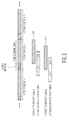
- an OFDM symbol structure in the time-domain is shown.
- an OFDM signal includes a number of OFDM symbols, e.g., OFDM symbol k-1, OFDM symbol k, and OFDM symbol k+1, each of which includes a guard interval.
- the OFDM symbol k contains a preamble symbol, which is a-priori known at the receiver
- the time-tracking process is implemented based on a cross-correlation between the extracted received signal and the known preamble sequence.
- two extracted receive signals 202 and 204 are shown.
- the lower extracted receive signal 202 is aligned with the left side of the guard interval for the OFDM symbol k, while the upper extracted receive signal 204 is aligned with the right side of the guard interval for the OFDM symbol k.
- the detection range of the cross-correlation for each of the extracted receive signal is limited to ⁇ FFT_SIZE/2.
- the catch range of the time-tracking process is effectively reduced by the guard interval.
- the catch range for out-of-guard channel taps is limited to ⁇ (FFT_SIZE/2 - guard interval).
- out-of-guard channel scenarios may occur, when for instance the local SFN tower is hidden (e.g. in a mountain area) and then SFN service is received from a far-way SFN station.
- the time-tracking process of an OFDM receiver must be capable of monitoring channel impulses which may exceed the guard interval.
- the catch range of the time-tracking algorithm at the receiver limits the reception capabilities, which may result in the loss of the SFN service.
- the synchronization and tracking unit 118 performs multiple time-shifted cross-correlations of the received signal with an a-priori known preamble symbol. The results of the different time-shifted cross-correlations are then used to resolve ambiguity issues for the channel delay.
- the synchronization and tracking unit 118 computes two (2) time-shifted cross-correlations of the received signal with the known preamble, e.g., a Time-Frequency-Phase-Reference (TFPR) symbol, which is used in DAB/DAB+, as illustrated in Fig. 3 , to increase the catch range of the time-tracking process.
- TFPR Time-Frequency-Phase-Reference
- Fig. 3 the same OFDM signal shown in Fig. 2 is used to illustrate the time-tracking process or algorithm.
- the same two extracted receive signals 202 and 204 are shown in Fig. 3 .
- each of the two extracted receive signals is associated with one of two (2) second extracted receive signals 302 and 304.
- the time shift or time difference between the two cross-correlations for the first extracted receive signal and the associated second receive signal is set to fast Fourier Transform size divided by 2 (FFT_SIZE/2) or half of FFT_SIZE.
- FFT_SIZE is mode dependent and can be either 256, 512, 1024 or 2048.
- Both cross-correlations provide the channel impulse response but shifted by the time shift of FFT_SIZE/2.
- the total time span of the associated first and second extracted receive signals together exceeds an OFDM symbol duration.
- the magnitude of the correlation results of both of the associated first and second cross-correlations depends on the overlap of the extracted received signal with the actual received delay taps, which are in the cross-correlation results.
- the delay taps show up as signal peaks above a noise threshold. The position of the peak corresponds to the signal delay and the magnitude corresponds to the received signal power.
- the magnitude of the first cross-correlation is greater than the magnitude of the second cross-correlation.
- the magnitude of the first cross-correlation is smaller than the magnitude of the second cross-correlation.
- each of first and second cross-correlation results is divided into four (4) delay segments I, II, III and IV.
- each delay segment is of length FFT_ - SIZE/4 or quarter of FFT_SIZE.
- the delay taps below to the four (4) delay segments I, II, III and IV as follows: Delay Segments Delay Taps for First Cross-Cowelation Delay Taps for Second Cross-Correlation I -FFT_SIZE/2 .... -FFT_SIZE/4-1 0 ... FFT_SIZE/4 - 1 II -FFT_SIZE/4 ...
- the second cross-correlation results contain the same delay taps as in the first cross-correlations results but at a position cyclically shifted by FFT_SIZE/2 and with a different magnitude.
- the delay segments I, II, III and IV for the second cross-correlation results have also been cyclically shifted by FFT_SIZE/2. This means that for both cross-correlation results, the same delay taps are contained in the same delay segments I, II, III and IV.
- the resolution of the delay taps is limited to -FFT_SIZE/2 ... FFT_SIZE/2-1.
- the ambiguity resolution performed by the synchronization and tracking unit 118 is described with reference to Fig. 5 .
- the first cross-correlation results are virtually extended to cover delay taps in a range -FFT_SIZE ... FFT_SIZE for the first cross-correlation results, and -FFT_SIZE/2 ... FFT_SIZE*3/2 for the second cross-correlation results, respectively.
- the delay taps in each delay segment have to be mapped to two (2) possible destinations.
- the delay taps in a first delay segment for the first cross-correlation results may be mapped to the left delay segment I interval (-FFT_SIZE/2 ....-FFT_SIZE/4-1) or to the right delay segment I interval (FFT_SIZE/2 ... FFT_SIZE ⁇ 3/4 - 1). This is simply due to the nature of cross-correlation in that the physical channel delay taps from both intervals totally overlap in the first cross-correlation results and cannot be separated using only the first cross-correlation results.
- One way to separate the physical channel delay taps is to use the second time-shifted cross-correlation results in which the same channel delay taps exist.
- the two destinations or intervals are selected by comparing the magnitude of the first cross-correlation results and the magnitude of the second cross-correlation results.
- the magnitude of cross-correlation results depends on accumulated signal energy in the extracted receive signal.
- the ambiguity issue is resolved by magnitude comparison with the corresponding correlation results, i.e., the delay tap (d2) in the second cross-correlation results ("xCorr2(d2)"), as follows: Delay Segment of xCorr1 Decision Criteria Delay After Ambiguity Resolution I
- the magnitude of each of the delay taps in the delay segment of the first cross-correlations results is compared with the magnitude of the corresponding delay taps in the same delay segment of the second cross-correlation results to determine the delay for that delay tap in the delay segment of the first cross-correlations results.
- the magnitude of each of the delay taps in the delay segment I of the first cross-correlations results is compared with the magnitude of the corresponding delay taps in the delay segment I of the second cross-correlation results to determine the delay for that delay tap in the delay segment I of the first cross-correlations results.
- the decision criteria are derived from simulations.
- the reliable detection range of both cross-correlations together is increased to ⁇ FFT_SIZE. Due to the uncertainty of the absolute timing position within the guard interval, the effective catch range of the time-tracking algorithm is increased to ⁇ (FFT_SIZE - guard interval).
- the synchronization and tracking unit includes 118 first and second cross-correlation modules 602 and 604, first and second division modules 606 and 608, and an ambiguity resolution module 610.
- These components of the synchronization and tracking unit may be implemented in any combination of hardware, software and firmware.
- the components of the synchronization and tracking unit are implemented as one or more software programs running on a system-on-chip.
- the first cross-correlation module 602 performs cross-correlation between the received signal and the a-priori known preamble, e.g., TFPR symbol.
- the first division module 606 then divides the results from the first cross-correlation results into a number of delay elements. In an embodiment, the first cross-correlation results are divided into four (4) delay segments I, II, III and IV, as described above.
- the second cross-correlation module 604 also performs cross-correlation between the received signal and the a-priori known preamble. However, this second cross-correlation is performed at a later time than the first cross-correlation. That is, the second cross-correlation is time-shifted with respect to the first cross-correlation. Similar to the first division module 606, the second division module 608 then divides the results from the second cross-correlation results into a number of delay elements. In an embodiment, the second cross-correlation results are also divided into four (4) delay segments I, II, III and IV, as described above.
- the ambiguity resolution module 610 operates to resolve ambiguity issues for the channel delay by comparing the magnitude of the first cross-correlation results with the magnitude of the second cross-correlation results for each delay segment of the first cross-correlation results, as described above.
- the basic principle described herein can also be applied for more than two (2) cross-correlations with different time offsets, in order to further enlarge the catch range of the time-tracking algorithm.
- the detection range enhancing technique described herein may be applied to other communication standards which transmit a-priori known preambles, e.g., 801.11(WiFi), Universal Mobile Telecommunications System (UMTS) and Long-Term Evolution (LTE).
- Fig. 7 depicts a flowchart diagram of one embodiment of a method for enhancing a detection range of a time-tracking process in a receiver.
- multiple cross-correlations are performed on different portions of a received signal with a known preamble sequence to derive multiple cross-correlation results.
- each of the cross-correlation results is divided into a plurality of delay segments.
- the delay segments of one of the multiple cross-correlation results are compared with the delay segments of another of the multiple cross-correlation results to determine delay of the delay segments of the one of the multiple cross-correlation results.
- firmware or software instructions stored on a readable storage medium for execution by a programmable logic device, such as an Application Specific Integrated Circuit (ASIC), a Field Programmable Gate Array (FPGA), a Programmable Logic Chip (PLC), a processor, or the like.
- ASIC Application Specific Integrated Circuit
- FPGA Field Programmable Gate Array
- PLC Programmable Logic Chip
- an embodiment of a program product includes a firmware package stored on a flash memory device and configured to cause an FPGA to perform the operations described herein.
Abstract
Description
- In orthogonal frequency-division multiplexing (OFDM) based single-frequency networks (SFNs), the same transmit signal is broadcasted simultaneously by various emitting towers on the same carrier frequency. The received signal at the receiver is always the superposition of all transmitted signals. Therefore, the channel impulse response contains all received signal paths, which are individually attenuated due to path loss and delayed due to their physical signal propagation.
- Those SFN signals which arrive at the receiver within the timespan of the guard interval contribute to the wanted signal energy. However, those signal parts which arrive outside of the guard interval contribute to inter-symbol-interference, and thus disturb the wanted signal reception.
- In a mobile environment, the attenuation of the received SFN signal contributions are continuously changing and fading. Therefore, the time-tracking algorithm at the receiver side is in charge to adjust the timing position for the fast Fourier transform (FFT) window extraction such that the signal-to-interference-plus-noise ratio (SINR) is maximized. For out-of guard channels, this means that the time-tracking algorithm needs to monitor all relevant signal contributions over time, and move the FFT window position accordingly.
- For a digital audio broadcasting (DAB) or DAB Plus (DAB+) receiver, the time-tracking algorithm is carried out on an a-priori known preamble symbol, e.g., TFPR symbol. A cross-correlation of the received signal with the perfectly known preamble provides the channel impulse response at the receive antenna. However, the cross-correlation of the preamble symbol has a limited detection range of ± FFT_SIZE/2. Thus, all delay taps which fall within the above detection range can be detected reliably. However, delay taps outside of the detection range become ambiguous and cannot be detected reliably or may even be misinterpreted. In addition, the correlation detection range can also be asymmetric e.g. - FFT_SIZE/4, ..., FFT_SIZE * 3/4, which may be difficult to model the power delay profile of the channel impulse response.
- A receiver component and a method for enhancing a detection range of a time synchronization process in a receiver utilize multiple cross-correlations of a received signal with a known preamble sequence. The results of the multiple cross-correlations are divided into delay segments. The delay segments of one of the multiple cross-correlations are compared with the delay segments of another of the multiple cross-correlations to determine delay of the delay segments of the one of the multiple cross-correlation results.
- In an embodiment, a method for enhancing a detection range of a time synchronization process in a receiver comprises performing multiple cross-correlations on different portions of a received signal with a known preamble sequence to derive multiple cross-correlation results, dividing each of the cross-correlation results into a plurality of delay segments, and comparing the delay segments of one of the multiple cross-correlation results with the delay segments of another of the multiple cross-correlation results to determine delay of the delay segments of the one of the multiple cross-correlation results.
- In an embodiment, a method for enhancing a detection range of a time synchronization process in a digital audio broadcasting based receiver comprises performing first and second cross-correlations on a received signal with a known preamble sequence to derive first and second cross-correlation results, wherein the second cross-correlation is time-shifted with respect to the first cross-correlation, dividing each of the first and second cross-correlation results into a plurality of delay segments, and comparing magnitude of the delay segments of the first cross-correlation results with magnitude of the delay segments of the second cross-correlation results to determine delay of the delay segments of the first cross-correlation results.
- In an embodiment, a component of a receiver comprises a plurality of cross-correlation modules configured to perform multiple cross-correlations on different portions of a received signal with a known preamble sequence to derive multiple cross-correlation results, a plurality of division modules coupled to the plurality of cross-correlation modules, the division modules being configured to divide each of the cross-correlation results into a plurality of delay segments, and an ambiguity resolution module configured to compare the delay segments of one of the multiple cross-correlation results with the delay segments of another of the multiple cross-correlation results to determine delay of the delay segments of the one of the multiple cross-correlation results.
- Other aspects in accordance with the invention will become apparent from the following detailed description, taken in conjunction with the accompanying drawings, illustrated by way of example of the principles of the invention.
-
-
Fig. 1 depicts a schematic block diagram of a dual tuner receiver in accordance with an embodiment of the invention. -
Fig. 2 depicts an OFDM symbol structure in the time-domain in which single cross-correlation is used for a time-tracking process. -
Fig. 3 depicts an OFDM symbol structure in the time-domain in which two (2) cross-correlations are used for the time-tracking process in accordance with an embodiment of the invention. -
Fig. 4 depicts first and second cross-correlation results, each of which has been divided into four (4) delay segments I, II, III and IV in accordance with an embodiment of the invention. -
Fig. 5 depicts first and second cross-correlation results, which have been virtually extended. -
Fig. 6 depicts a block diagram of components of a synchronization and tracking unit of the dual tuner receiver in accordance with an embodiment of the invention. -
Fig. 7 depicts a flowchart diagram of one embodiment of a method for enhancing a detection range of a time-tracking process in a receiver. - Throughout the description, similar reference numbers may be used to identify similar elements.
- It will be readily understood that the components of the embodiments as generally described herein and illustrated in the appended figures could be arranged and designed in a wide variety of different configurations. Thus, the following more detailed description of various embodiments, as represented in the figures, is not intended to limit the scope of the present disclosure, but is merely representative of various embodiments. While the various aspects of the embodiments are presented in drawings, the drawings are not necessarily drawn to scale unless specifically indicated.
- The described embodiments are to be considered in all respects only as illustrative and not restrictive. The scope of the invention is, therefore, indicated by the appended claims rather than by this detailed description. All changes which come within the meaning and range of equivalency of the claims are to be embraced within their scope.
- Reference throughout this specification to features, advantages, or similar language does not imply that all of the features and advantages that may be realized with the present invention should be or are in any single embodiment of the invention. Rather, language referring to the features and advantages is understood to mean that a specific feature, advantage, or characteristic described in connection with an embodiment is included in at least one embodiment of the present invention. Thus, discussions of the features and advantages, and similar language, throughout this specification may, but do not necessarily, refer to the same embodiment.
- Furthermore, the described features, advantages, and characteristics of the invention may be combined in any suitable manner in one or more embodiments. One skilled in the relevant art will recognize, in light of the description herein, that the invention can be practiced without one or more of the specific features or advantages of a particular embodiment. In other instances, additional features and advantages may be recognized in certain embodiments that may not be present in all embodiments of the invention.
- Reference throughout this specification to "one embodiment," "an embodiment," or similar language means that a particular feature, structure, or characteristic described in connection with the indicated embodiment is included in at least one embodiment of the present invention. Thus, the phrases "in one embodiment," "in an embodiment," and similar language throughout this specification may, but do not necessarily, all refer to the same embodiment.
- Embodiments of the invention enable a receiver that receives signals with a-priori known preambles, such as DAB/DAB+ receivers, to increase the detection range of the time-tracking process or algorithm performed in the receiver. As described in more detail below, embodiments of the invention utilize multiple time-shifted cross-correlation of the received signal to enhance the detection range. In addition, in one or more embodiments of the invention resolves ambiguity that arise from using multiple cross-correlation results of the same receive signal.
-
Fig. 1 is a schematic block diagram of adual tuner receiver 100 in accordance with an embodiment of the invention. In the embodiment depicted inFig. 1 , the dual tuner receiver is a digital audio broadcast (DAB) based receiver that includesantennas units symbol processing units processing units tracking unit 118, a combiningunit 120, achannel decoder 122 and asource decoder 124. These components of the dual tuner receiver may be implemented in any combination of hardware, software and firmware. - The
dual tuner receiver 100 has two receive paths. The first receive path is provided by theantenna 102, the digital front-end processing unit 106, thesymbol processing unit 110 and theDQPSK processing unit 114. The digital front-end processing unit 106 processes the signal received via theantenna 102. The digital front-end processing unit 106 performs front-end signal processes such as analog-to-digital conversion, automatic gain control and automatic frequency control. Thesymbol processing unit 110 extracts symbols from the received signal using time synchronization and tracking information provided by the synchronization andtracking unit 118, which is described below. The DQPSK processing unit performs DQPSK demodulation, as well as log-likelihood ratio (LLR) computation. - The second receive path is provided by the
antenna 104, the digital front-end processing unit 108, thesymbol processing unit 112 and the DQPSKprocessing unit 116. The digital front-end processing unit 108, thesymbol processing unit 112 and theDQPSK processing unit 116 operate on the signal received via theantenna 104 in a similar manner as the digital front-end processing unit 106, thesymbol processing unit 110 and theDQPSK processing unit 114 for the first receive path. In particular, thesymbol processing unit 112 extracts symbols from the received signal on the second receive path using time synchronization and tracking information provided by the synchronization andtracking unit 118. - The combining
unit 120 of thedual tuner receiver 100 operates to combine the received signals on the first and second receive paths. The combining process may be a maximal-ratio combining (MRC) process or an equal-gain combining (EQC) process. Thechannel decoder 122 then performs a channel decoding process, which may involve de-scrambling, de-interleaving and Viterbi decoding. Lastly, thesource decoder 124 performs a source decoding process, which may involve de-multiplexing and audio decoding. The output of the source decoder is the desired audio signal. - As noted above, the synchronization and
tracking unit 118 provides time synchronization and tracking information to thesymbol processing units - Turning now to
Fig. 2 , an OFDM symbol structure in the time-domain is shown. As shown inFig. 2 , an OFDM signal includes a number of OFDM symbols, e.g., OFDM symbol k-1, OFDM symbol k, and OFDM symbol k+1, each of which includes a guard interval. Assuming that the OFDM symbol k contains a preamble symbol, which is a-priori known at the receiver, the time-tracking process is implemented based on a cross-correlation between the extracted received signal and the known preamble sequence. InFig. 2 , two extracted receivesignals signal 202 is aligned with the left side of the guard interval for the OFDM symbol k, while the upper extracted receivesignal 204 is aligned with the right side of the guard interval for the OFDM symbol k. The detection range of the cross-correlation for each of the extracted receive signal is limited to ± FFT_SIZE/2. However, due to the fact that the absolute timing position can vary within the guard interval, the catch range of the time-tracking process is effectively reduced by the guard interval. Thus, using cross-correlation between the extracted received signal and the known preamble sequence, the catch range for out-of-guard channel taps is limited to ± (FFT_SIZE/2 - guard interval). - In SFN networks, out-of-guard channel scenarios may occur, when for instance the local SFN tower is hidden (e.g. in a mountain area) and then SFN service is received from a far-way SFN station. In this situation, the time-tracking process of an OFDM receiver must be capable of monitoring channel impulses which may exceed the guard interval. However, the catch range of the time-tracking algorithm at the receiver limits the reception capabilities, which may result in the loss of the SFN service.
- In order to enlarge the catch range of the time-tracking process, the synchronization and
tracking unit 118 performs multiple time-shifted cross-correlations of the received signal with an a-priori known preamble symbol. The results of the different time-shifted cross-correlations are then used to resolve ambiguity issues for the channel delay. - In an embodiment, the synchronization and
tracking unit 118 computes two (2) time-shifted cross-correlations of the received signal with the known preamble, e.g., a Time-Frequency-Phase-Reference (TFPR) symbol, which is used in DAB/DAB+, as illustrated inFig. 3 , to increase the catch range of the time-tracking process. InFig. 3 , the same OFDM signal shown inFig. 2 is used to illustrate the time-tracking process or algorithm. In addition, the same two extracted receivesignals Fig. 3 . However, in this embodiment, each of the two extracted receive signals is associated with one of two (2) second extracted receivesignals - Both cross-correlations provide the channel impulse response but shifted by the time shift of FFT_SIZE/2. The total time span of the associated first and second extracted receive signals together exceeds an OFDM symbol duration. For the channel impulse response, this means that the magnitude of the correlation results of both of the associated first and second cross-correlations depends on the overlap of the extracted received signal with the actual received delay taps, which are in the cross-correlation results. In cross-correlation results with FFT_SIZE values, the delay taps show up as signal peaks above a noise threshold. The position of the peak corresponds to the signal delay and the magnitude corresponds to the received signal power. For channel delay taps with a delay > 0, the magnitude of the first cross-correlation is greater than the magnitude of the second cross-correlation. For channel delay taps with a delay < -FFT_SIZE/2, the magnitude of the first cross-correlation is smaller than the magnitude of the second cross-correlation. These characteristics of the cross-correlation results are used to resolve ambiguity issues for the channel delay, as described below.
- In order to resolve the ambiguity issues, as illustrated in
Fig. 4 , each of first and second cross-correlation results is divided into four (4) delay segments I, II, III and IV. As shown inFig. 4 , each delay segment is of length FFT_-SIZE/4 or quarter of FFT_SIZE. For the first and second cross-correlation results, the delay taps below to the four (4) delay segments I, II, III and IV as follows:Delay Segments Delay Taps for First Cross-Cowelation Delay Taps for Second Cross-Correlation I -FFT_SIZE/2 .... -FFT_SIZE/4-1 0 ... FFT_SIZE/4 - 1 II -FFT_SIZE/4 ... - 1 FFT SIZE/4 ... FFT_SIZE/2 - 1 III 0 ... FFT_SIZE/4 - 1 -FFT_SIZE/2 .... -FFT_SIZE/4-1 IV FFT_SIZE/4 ... FFT_SIZE/2 - 1 -FFT_SIZE/4 ... - 1 - Due to the time shift of FFT_SIZE/2 for the second extracted signal, the second cross-correlation results contain the same delay taps as in the first cross-correlations results but at a position cyclically shifted by FFT_SIZE/2 and with a different magnitude. The delay segments I, II, III and IV for the second cross-correlation results have also been cyclically shifted by FFT_SIZE/2. This means that for both cross-correlation results, the same delay taps are contained in the same delay segments I, II, III and IV. Considering only a single cross-correlation, the resolution of the delay taps is limited to -FFT_SIZE/2 ... FFT_SIZE/2-1. Due to the cyclic nature of the cross-correlation, those delay taps which exceed the above range will occur in the cross-correlation results but at a position which is cyclically shifted by FFT_SIZE. For instance, delay taps of FFT_SIZE/2 ... FFT_SIZE*3/4 will occur in the first cross-correlation results at delay segment I. Thus, for enlarging the catch range of the time-tracking algorithm, an ambiguity resolution is required which allows for reliable detection of delay taps within -FFT_SIZE ... FFT_SIZE-1.
- The ambiguity resolution performed by the synchronization and
tracking unit 118 is described with reference toFig. 5 . InFig. 5 , the first cross-correlation results are virtually extended to cover delay taps in a range -FFT_SIZE ... FFT_SIZE for the first cross-correlation results, and -FFT_SIZE/2 ... FFT_SIZE*3/2 for the second cross-correlation results, respectively. - For ambiguity resolution in the first cross-correlation results, the delay taps in each delay segment have to be mapped to two (2) possible destinations. As an example, the delay taps in a first delay segment for the first cross-correlation results may be mapped to the left delay segment I interval (-FFT_SIZE/2 ....-FFT_SIZE/4-1) or to the right delay segment I interval (FFT_SIZE/2 ... FFT_SIZE · 3/4 - 1). This is simply due to the nature of cross-correlation in that the physical channel delay taps from both intervals totally overlap in the first cross-correlation results and cannot be separated using only the first cross-correlation results. One way to separate the physical channel delay taps is to use the second time-shifted cross-correlation results in which the same channel delay taps exist. The two destinations or intervals are selected by comparing the magnitude of the first cross-correlation results and the magnitude of the second cross-correlation results. The magnitude of cross-correlation results depends on accumulated signal energy in the extracted receive signal.
- For each delay tap (d1) in the first cross-correlation results ("xCorr1(d1)"), the ambiguity issue is resolved by magnitude comparison with the corresponding correlation results, i.e., the delay tap (d2) in the second cross-correlation results ("xCorr2(d2)"), as follows:
Delay Segment of xCorr1 Decision Criteria Delay After Ambiguity Resolution I |xCorr1(d1)| < |2·xCorr2(d2)| If true: -FFT_SIZE/2 ... -FFT_SIZE/4 - 1 If false: FFT_SIZE/2 ... FFT_SIZE · 3/4 - 1 II |xCorr1(d1)| < |8·xCorr2(d2)| If true: -FFT_SIZE/4 ... -1 If false: FFT SIZE · 3/4 ... FFT_SIZE -1 III |xCorr(d1)| > |xCorr2(d2)| If true: 0 ... FFT_SIZE/4 - 1 If false: -FFT_SIZE ... -FFT_SIZE · 3/4 - 1 IV |xCorr1(d1)| > |xCorr2(d2)| If true: FFT_SIZE/4... FFT_SIZE/2 - 1 If false: -FFT_SIZE · 3/4 ... -FFT_SIZE/2 - 1 - In the above table, for each of the delay segments I, II, III and IV, the magnitude of each of the delay taps in the delay segment of the first cross-correlations results is compared with the magnitude of the corresponding delay taps in the same delay segment of the second cross-correlation results to determine the delay for that delay tap in the delay segment of the first cross-correlations results. As an example, for the delay segment I, the magnitude of each of the delay taps in the delay segment I of the first cross-correlations results is compared with the magnitude of the corresponding delay taps in the delay segment I of the second cross-correlation results to determine the delay for that delay tap in the delay segment I of the first cross-correlations results. The decision criteria are derived from simulations.
- After ambiguity resolution, the reliable detection range of both cross-correlations together is increased to ± FFT_SIZE. Due to the uncertainty of the absolute timing position within the guard interval, the effective catch range of the time-tracking algorithm is increased to ± (FFT_SIZE - guard interval).
- Turning now to
Fig. 6 , components of the synchronization andtracking unit 118 are shown in accordance with an embodiment of the invention. As shown inFig. 6 , in this embodiment, the synchronization and tracking unit includes 118 first andsecond cross-correlation modules second division modules ambiguity resolution module 610. These components of the synchronization and tracking unit may be implemented in any combination of hardware, software and firmware. In a particular embodiment, the components of the synchronization and tracking unit are implemented as one or more software programs running on a system-on-chip. - The
first cross-correlation module 602 performs cross-correlation between the received signal and the a-priori known preamble, e.g., TFPR symbol. Thefirst division module 606 then divides the results from the first cross-correlation results into a number of delay elements. In an embodiment, the first cross-correlation results are divided into four (4) delay segments I, II, III and IV, as described above. - The
second cross-correlation module 604 also performs cross-correlation between the received signal and the a-priori known preamble. However, this second cross-correlation is performed at a later time than the first cross-correlation. That is, the second cross-correlation is time-shifted with respect to the first cross-correlation. Similar to thefirst division module 606, thesecond division module 608 then divides the results from the second cross-correlation results into a number of delay elements. In an embodiment, the second cross-correlation results are also divided into four (4) delay segments I, II, III and IV, as described above. - The
ambiguity resolution module 610 operates to resolve ambiguity issues for the channel delay by comparing the magnitude of the first cross-correlation results with the magnitude of the second cross-correlation results for each delay segment of the first cross-correlation results, as described above. - Although embodiments of the invention have been described herein for two (2) time-shifted cross-correlations, the basic principle described herein can also be applied for more than two (2) cross-correlations with different time offsets, in order to further enlarge the catch range of the time-tracking algorithm. In addition, the detection range enhancing technique described herein may be applied to other communication standards which transmit a-priori known preambles, e.g., 801.11(WiFi), Universal Mobile Telecommunications System (UMTS) and Long-Term Evolution (LTE).
-
Fig. 7 depicts a flowchart diagram of one embodiment of a method for enhancing a detection range of a time-tracking process in a receiver. Atblock 702, multiple cross-correlations are performed on different portions of a received signal with a known preamble sequence to derive multiple cross-correlation results. Atblock 704, each of the cross-correlation results is divided into a plurality of delay segments. Atblock 706, the delay segments of one of the multiple cross-correlation results are compared with the delay segments of another of the multiple cross-correlation results to determine delay of the delay segments of the one of the multiple cross-correlation results. - It should also be noted that at least some of the operations for the methods described herein may be implemented using firmware or software instructions stored on a readable storage medium for execution by a programmable logic device, such as an Application Specific Integrated Circuit (ASIC), a Field Programmable Gate Array (FPGA), a Programmable Logic Chip (PLC), a processor, or the like. As an example, an embodiment of a program product includes a firmware package stored on a flash memory device and configured to cause an FPGA to perform the operations described herein.
- In the above description, specific details of various embodiments are provided. However, some embodiments may be practiced with less than all of these specific details. In other instances, certain methods, procedures, components, structures, and/or functions are described in no more detail than to enable the various embodiments of the invention, for the sake of brevity and clarity.
- Although the operations of the method(s) herein are shown and described in a particular order, the order of the operations of each method may be altered so that certain operations may be performed in an inverse order or so that certain operations may be performed, at least in part, concurrently with other operations. In another embodiment, instructions or sub-operations of distinct operations may be implemented in an intermittent and/or alternating manner.
- Although specific embodiments of the invention have been described and illustrated, the invention is not to be limited to the specific forms or arrangements of parts so described and illustrated. The scope of the invention is to be defined by the claims appended hereto and their equivalents.
Claims (15)
- A method for enhancing a detection range of a time-tracking process in a receiver, the method comprising:performing multiple cross-correlations on different portions of a received signal with a known preamble sequence to derive multiple cross-correlation results;dividing each of the cross-correlation results into a plurality of delay segments; andcomparing the delay segments of one of the multiple cross-correlation results with the delay segments of another of the multiple cross-correlation results to determine delay of the delay segments of the one of the multiple cross-correlation results.
- The method of claim 1, wherein comparing the delay segments of one of the multiple cross-correlation results with the delay segments of another of the multiple cross-correlation results includes comparing magnitudes of the delay segments of one of the multiple cross-correlation results with magnitudes of the delay segments of another of the multiple cross-correlation results to determine delay of the delay segments of the one of the multiple cross-correlation results.
- The method of claim 1, wherein performing the multiple cross-correlations includes performing a first cross-correlation on a first portion of the received signal with the known preamble sequence and performing a second cross-correlation on a second portion of the received signal with the known preamble sequence, the second cross-correlation being performed at a later time than the first cross-correlation.
- The method of claim 3, wherein a time difference between performing the first cross-correlation and performing the second cross-correlation is set to half of fast Fourier Transform size used by the receiver.
- The method of claim 1, wherein dividing each of the cross-correlation results into a plurality of delay segments includes dividing each of the cross-correlation results into four delay segments.
- The method of claim 5, wherein the length of each of the delay segment is set to quarter of fast Fourier Transform size used by the receiver.
- The method of claim 1, wherein the known preamble sequence includes Time-Frequency-Phase-Reference (TFPR) symbol.
- The method of claim 1, wherein the received signal is an orthogonal frequency-division multiplexing (OFDM) based signal.
- A component of a receiver comprising:a plurality of cross-correlation modules configured to perform multiple cross-correlations on different portions of a received signal with a known preamble sequence to derive multiple cross-correlation results;a plurality of division modules coupled to the plurality of cross-correlation modules, the division modules being configured to divide each of the cross-correlation results into a plurality of delay segments; andan ambiguity resolution module configured to compare the delay segments of one of the multiple cross-correlation results with the delay segments of another of the multiple cross-correlation results to determine delay of the delay segments of the one of the multiple cross-correlation results.
- The component of claim 9, wherein the ambiguity resolution module is configured to compare magnitudes of the delay segments of one of the multiple cross-correlation results with magnitudes of the delay segments of another of the multiple cross-correlation results to determine delay of the delay segments of the one of the multiple cross-correlation results.
- The component of claim 9, wherein the plurality of cross-correlation modules are configured to perform a first cross-correlation on a first portion of the received signal with the known preamble sequence and to perform a second cross-correlation on a second portion of the received signal with the known preamble sequence, the second cross-correlation being performed at a later time than the first cross-correlation.
- The component of claim 11, wherein a time difference between performing the first cross-correlation and performing the second cross-correlation is set to half of fast Fourier Transform size used by the receiver.
- The component of claim 9, wherein the plurality of division modules is configured to divide each of the cross-correlation results into four delay segments.
- The component of claim 13, wherein the length of each of the delay segment is set to quarter of fast Fourier Transform size used by the receiver.
- A method for enhancing a detection range of a time-tracking process in a digital audio broadcasting based receiver, the method comprising:performing first and second cross-correlations on a received signal with a known preamble sequence to derive first and second cross-correlation results, wherein the second cross-correlation is time-shifted with respect to the first cross-correlation;dividing each of the first and second cross-correlation results into a plurality of delay segments; andcomparing magnitude of the delay segments of the first cross-correlation results with magnitude of the delay segments of the second cross-correlation results to determine delay of the delay segments of the first cross-correlation results.
Applications Claiming Priority (1)
| Application Number | Priority Date | Filing Date | Title |
|---|---|---|---|
| US14/863,572 US9520910B1 (en) | 2015-09-24 | 2015-09-24 | Receiver component and method for enhancing a detection range of a time-tracking process in a receiver |
Publications (2)
| Publication Number | Publication Date |
|---|---|
| EP3151494A1 true EP3151494A1 (en) | 2017-04-05 |
| EP3151494B1 EP3151494B1 (en) | 2019-11-06 |
Family
ID=56985447
Family Applications (1)
| Application Number | Title | Priority Date | Filing Date |
|---|---|---|---|
| EP16187678.4A Active EP3151494B1 (en) | 2015-09-24 | 2016-09-07 | Receiver component and method for enhancing a detection range of a time-tracking process in a receiver |
Country Status (3)
| Country | Link |
|---|---|
| US (1) | US9520910B1 (en) |
| EP (1) | EP3151494B1 (en) |
| CN (1) | CN106559155B (en) |
Citations (5)
| Publication number | Priority date | Publication date | Assignee | Title |
|---|---|---|---|---|
| US5727018A (en) * | 1993-05-28 | 1998-03-10 | Siemens Aktiengesellschaft | Process for obtaining a signal indicating a synchronization error between a pseudo-random signal sequence from a transmitter and a reference pseudo-random signal sequence from a receiver |
| US20070036235A1 (en) * | 1999-02-24 | 2007-02-15 | Sony Deutschland Gmbh | Transmitting apparatus and method for a digital telecommunication system |
| US20080279322A1 (en) * | 2007-02-05 | 2008-11-13 | Sequans Communications | Method and device for timing synchronization and neighbor scanning for cellular OFDM systems |
| US20110170442A1 (en) * | 2010-01-12 | 2011-07-14 | Samsung Electronics Co. Ltd. | Method for estimating carrier-to-noise ratio and base station apparatus using the same in a wireless access system |
| US20140140449A1 (en) * | 2012-11-16 | 2014-05-22 | Sony Mobile Communications, Inc. | Communication method and reception apparatus |
Family Cites Families (60)
| Publication number | Priority date | Publication date | Assignee | Title |
|---|---|---|---|---|
| DE3224768A1 (en) * | 1982-07-02 | 1984-01-05 | Philips Patentverwaltung Gmbh, 2000 Hamburg | ARRANGEMENT FOR INTERRUPTING SIGNALS |
| US5140617A (en) * | 1990-02-07 | 1992-08-18 | Mitsubishi Denki Kabushiki Kaisha | Frame phase estimation method and circuit |
| JP3272940B2 (en) * | 1996-03-07 | 2002-04-08 | ケイディーディーアイ株式会社 | Spread spectrum signal demodulator |
| JP3377451B2 (en) * | 1998-08-26 | 2003-02-17 | シャープ株式会社 | Matched filter |
| JP3486576B2 (en) * | 1999-05-18 | 2004-01-13 | シャープ株式会社 | OFDM receiver and frequency offset compensation method thereof |
| ATE263380T1 (en) * | 2000-01-26 | 2004-04-15 | Instro Prec Ltd | OPTICAL DISTANCE MEASUREMENT |
| JP3407711B2 (en) * | 2000-04-27 | 2003-05-19 | 日本電気株式会社 | Path search circuit in DS-CDMA receiver |
| JP4815661B2 (en) * | 2000-08-24 | 2011-11-16 | ソニー株式会社 | Signal processing apparatus and signal processing method |
| JP2002152082A (en) * | 2000-11-07 | 2002-05-24 | Mitsubishi Electric Corp | Automatic frequency control apparatus and spectrum diffusion reception device |
| JP3636145B2 (en) * | 2001-06-15 | 2005-04-06 | ソニー株式会社 | Demodulation timing generation circuit and demodulation device |
| US6859641B2 (en) * | 2001-06-21 | 2005-02-22 | Applied Signal Technology, Inc. | Adaptive canceller for frequency reuse systems |
| US6594201B2 (en) * | 2001-10-23 | 2003-07-15 | Lockheed Martin Corporation | System and method for localizing targets using multiple arrays |
| US6714607B2 (en) * | 2001-12-20 | 2004-03-30 | Sbc Technology Resources, Inc. | Joint demodulation using a viterbi equalizer having an adaptive total number of states |
| GB2384651B (en) * | 2002-01-28 | 2004-03-24 | Toshiba Res Europ Ltd | Signal selection systems |
| JP4043335B2 (en) * | 2002-10-08 | 2008-02-06 | 株式会社日立国際電気 | Receiver |
| US7224721B2 (en) * | 2002-10-11 | 2007-05-29 | The Mitre Corporation | System for direct acquisition of received signals |
| US7486751B1 (en) * | 2004-02-18 | 2009-02-03 | Ralink Technology, Inc. | Joint time/frequency domain maximum ratio combining architectures for multi input multi output wireless receivers |
| CA2433139C (en) * | 2003-06-23 | 2012-03-27 | Wavesat Wireless Inc. | Synchronizing method and apparatus |
| US7366089B2 (en) * | 2003-10-08 | 2008-04-29 | Atheros Communications, Inc. | Apparatus and method of multiple antenna receiver combining of high data rate wideband packetized wireless communication signals |
| US7809020B2 (en) * | 2003-10-31 | 2010-10-05 | Cisco Technology, Inc. | Start of packet detection for multiple receiver combining and multiple input multiple output radio receivers |
| JP4291674B2 (en) * | 2003-11-11 | 2009-07-08 | 株式会社エヌ・ティ・ティ・ドコモ | OFDM transmitter and OFDM receiver |
| US7298780B2 (en) * | 2003-12-12 | 2007-11-20 | Nokia Corporation | Multiple access using different codes lengths for global navigation satellite systems |
| US7545891B1 (en) * | 2004-03-09 | 2009-06-09 | Ralink Technology, Inc. | Carrier recovery architectures for multi input multi output orthogonal frequency division multiplexing receivers |
| KR101029811B1 (en) * | 2004-09-17 | 2011-04-20 | 엘지전자 주식회사 | Apparatus of frequency recovery in Digital receiver and Method of the same |
| JP2006148854A (en) * | 2004-10-21 | 2006-06-08 | Hitachi Kokusai Electric Inc | Multicarrier receiver and transmitter with delay correcting function |
| US20060267811A1 (en) * | 2005-05-24 | 2006-11-30 | Kan Tan | Method and apparatus for reconstructing signals from sub-band signals |
| US7738538B1 (en) * | 2005-08-01 | 2010-06-15 | Ralink Technology Corporation | Flexible and in-band signaling for nested preamble |
| US7664164B1 (en) * | 2006-02-10 | 2010-02-16 | L-3 Communications, Corp. | Correlation apparatus and method for accomodating spreading code frequency offset |
| JP4837403B2 (en) * | 2006-03-08 | 2011-12-14 | ルネサスエレクトロニクス株式会社 | Synchronization timing detection device, reception device, and synchronization timing detection method |
| EP1876730A1 (en) * | 2006-07-05 | 2008-01-09 | Koninklijke Philips Electronics N.V. | Bandwidth asymmetric communication system |
| SG141260A1 (en) * | 2006-09-12 | 2008-04-28 | Oki Techno Ct Singapore Pte | An apparatus, a receiver and a method for timing recovery in an ofdm system |
| KR100789921B1 (en) * | 2006-11-07 | 2008-01-02 | 한국전자통신연구원 | Apparatus and method for detecting preamble packet in orthogonal frequency-division multiplexing system |
| US7830949B2 (en) * | 2007-02-14 | 2010-11-09 | Wilinx Corporation | Cross correlation circuits and methods |
| CN101282128B (en) * | 2007-04-03 | 2014-01-01 | 中兴通讯股份有限公司南京分公司 | Method for reinforcing predecessor of broadband radio communication system |
| US8131218B2 (en) * | 2007-04-13 | 2012-03-06 | General Dynamics C4 Systems, Inc. | Methods and apparatus for wirelessly communicating signals that include embedded synchronization/pilot sequences |
| JP4321630B2 (en) * | 2007-06-29 | 2009-08-26 | ソニー株式会社 | Tracking error signal detection apparatus and optical disk apparatus |
| US9049091B2 (en) * | 2008-01-29 | 2015-06-02 | Keysight Technologies, Inc. | System and method for in-phase/quadrature-phase (I/Q) time delay measurement and compensation |
| US8331422B2 (en) * | 2008-02-28 | 2012-12-11 | Magellan Systems Japan, Inc. | Method and apparatus for acquisition, tracking, and transfer using sub-microsecond time transfer using weak GPS/GNSS signals |
| US8184816B2 (en) * | 2008-03-18 | 2012-05-22 | Qualcomm Incorporated | Systems and methods for detecting wind noise using multiple audio sources |
| US8169993B2 (en) * | 2008-04-16 | 2012-05-01 | Anritsu Company | Method and apparatus to estimate wireless base station signal quality over the air |
| US20090323980A1 (en) * | 2008-06-26 | 2009-12-31 | Fortemedia, Inc. | Array microphone system and a method thereof |
| JP4577435B2 (en) * | 2008-09-30 | 2010-11-10 | ソニー株式会社 | Tracking error signal detection apparatus and optical disk apparatus |
| US8442141B1 (en) * | 2009-04-07 | 2013-05-14 | Marvell International Ltd. | Opportunistic beamforming in a wireless communication system |
| JP5032538B2 (en) * | 2009-08-28 | 2012-09-26 | 株式会社東芝 | Transmission line response estimator |
| JP5278557B2 (en) * | 2009-12-03 | 2013-09-04 | 富士通株式会社 | Base station, signal processing method |
| US7920599B1 (en) * | 2010-02-03 | 2011-04-05 | Anna University | Methods and systems for synchronizing wireless transmission of data packets |
| US8344947B2 (en) * | 2010-09-14 | 2013-01-01 | Cellguide Ltd. | Multipath mitigation in positioning systems |
| US8625697B2 (en) * | 2011-07-08 | 2014-01-07 | I-Shou University | OFDM beamformer, and a signal receiving system incorporating the same |
| US8842498B2 (en) * | 2012-04-12 | 2014-09-23 | Ceebus Technologies Llc | Underwater acoustic array, communication and location system |
| US9503202B2 (en) * | 2012-04-12 | 2016-11-22 | Ceebus Technologies, Llc | Underwater acoustic array, communication and location system |
| US20140365134A1 (en) * | 2012-06-29 | 2014-12-11 | Leo Eisner | Method Discriminating Between Natural And Induced Seismicity |
| US9065630B1 (en) * | 2012-09-27 | 2015-06-23 | Marvell International Ltd. | Systems and methods for detecting secondary synchronization signals in a wireless communication system |
| US9485130B2 (en) * | 2012-10-21 | 2016-11-01 | Semitech Semiconductor Pty. Ltd. | Universal OFDM synchronizer for power line communication |
| JP6015387B2 (en) * | 2012-11-29 | 2016-10-26 | 富士通株式会社 | Delay amount estimation apparatus and delay amount estimation method |
| WO2014128995A1 (en) * | 2013-02-25 | 2014-08-28 | 三菱電機株式会社 | Passive radar device |
| US9307318B2 (en) * | 2013-03-07 | 2016-04-05 | Silicon Laboratories Inc. | Audio processor circuits for acoustic echo cancellation and method therefor |
| EP2974386A1 (en) * | 2013-03-14 | 2016-01-20 | Apple Inc. | Adaptive room equalization using a speaker and a handheld listening device |
| US9702960B2 (en) * | 2013-03-15 | 2017-07-11 | Raytheon Company | Frequency difference of arrival (FDOA) for geolocation |
| US9270323B2 (en) * | 2014-04-04 | 2016-02-23 | Broadcom Corporation | Wireless communication synchronization system |
| US9826263B2 (en) * | 2014-10-22 | 2017-11-21 | Arcom Digital, Llc | Detecting CPD in HFC network with OFDM signals |
-
2015
- 2015-09-24 US US14/863,572 patent/US9520910B1/en active Active
-
2016
- 2016-09-06 CN CN201610806000.XA patent/CN106559155B/en active Active
- 2016-09-07 EP EP16187678.4A patent/EP3151494B1/en active Active
Patent Citations (5)
| Publication number | Priority date | Publication date | Assignee | Title |
|---|---|---|---|---|
| US5727018A (en) * | 1993-05-28 | 1998-03-10 | Siemens Aktiengesellschaft | Process for obtaining a signal indicating a synchronization error between a pseudo-random signal sequence from a transmitter and a reference pseudo-random signal sequence from a receiver |
| US20070036235A1 (en) * | 1999-02-24 | 2007-02-15 | Sony Deutschland Gmbh | Transmitting apparatus and method for a digital telecommunication system |
| US20080279322A1 (en) * | 2007-02-05 | 2008-11-13 | Sequans Communications | Method and device for timing synchronization and neighbor scanning for cellular OFDM systems |
| US20110170442A1 (en) * | 2010-01-12 | 2011-07-14 | Samsung Electronics Co. Ltd. | Method for estimating carrier-to-noise ratio and base station apparatus using the same in a wireless access system |
| US20140140449A1 (en) * | 2012-11-16 | 2014-05-22 | Sony Mobile Communications, Inc. | Communication method and reception apparatus |
Also Published As
| Publication number | Publication date |
|---|---|
| EP3151494B1 (en) | 2019-11-06 |
| CN106559155B (en) | 2020-01-03 |
| CN106559155A (en) | 2017-04-05 |
| US9520910B1 (en) | 2016-12-13 |
Similar Documents
| Publication | Publication Date | Title |
|---|---|---|
| US8462647B2 (en) | Method and system for multiple frequency hypothesis testing with full synch acquisition in an E-UTRA/LTE UE receiver | |
| US20140314128A1 (en) | Methods for LTE Cell Search with Large Frequency Offset | |
| JP2013059037A5 (en) | ||
| US8401123B2 (en) | Method and system for increasing the accuracy of frequency offset estimation in multiple frequency hypothesis testing in an E-UTRA/LTE UE receiver | |
| US8326251B2 (en) | Method and system for estimating a receiver frequency offset in a communication system | |
| US7885356B2 (en) | Receiver and receiving method | |
| CN102497349B (en) | Multi-strategy-combined OFDM (Orthogonal Frequency Division Multiplexing) frame synchronization method | |
| WO2018111465A3 (en) | Data detection in mimo systems with demodulation and tracking reference signals | |
| CN1308427A (en) | Signal structure, detection and estimation of timing sync and access of upstream link | |
| WO2016054999A1 (en) | Signal format for cell search and synchronization in wireless networks | |
| JP4904929B2 (en) | OFDM receiver, interference wave discrimination method, window control device, and window control method | |
| KR20080016159A (en) | Method and apparatus for cell search in communication system | |
| CN109474369B (en) | Physical broadcast channel demodulation method, device, readable storage medium and user terminal | |
| US20120230453A1 (en) | Channel estimation and symbol boundary detection method | |
| KR20120042138A (en) | Method for searching cell in wireless communication system | |
| US7801088B2 (en) | Synchronous orthogonal frequency division multiplexing receiving apparatus in multi-cell environment and method thereof | |
| EP2127190A1 (en) | Robust synchronization for time division duplex signal | |
| US9548836B2 (en) | Upstream burst noise detection | |
| CN102907150A (en) | Method and apparatus for improved base station cell synchronization in LTE downlink | |
| EP3151494B1 (en) | Receiver component and method for enhancing a detection range of a time-tracking process in a receiver | |
| CN105282080B (en) | OFDM symbol sync bit searching method and its synchronizing device | |
| US20060140110A1 (en) | Method and system for joint mode and guard interval detection | |
| US20110243105A1 (en) | Method and system for automatically rescaling an accumulation buffer in synchronization systems | |
| US9825737B2 (en) | Method and device for detecting secondary synchronization signal in LTE and LTE advanced communication system | |
| US9203670B2 (en) | Frame structure for terrestrial cloud broadcast and a method of receiving the same |
Legal Events
| Date | Code | Title | Description |
|---|---|---|---|
| PUAI | Public reference made under article 153(3) epc to a published international application that has entered the european phase |
Free format text: ORIGINAL CODE: 0009012 |
|
| STAA | Information on the status of an ep patent application or granted ep patent |
Free format text: STATUS: THE APPLICATION HAS BEEN PUBLISHED |
|
| AK | Designated contracting states |
Kind code of ref document: A1 Designated state(s): AL AT BE BG CH CY CZ DE DK EE ES FI FR GB GR HR HU IE IS IT LI LT LU LV MC MK MT NL NO PL PT RO RS SE SI SK SM TR |
|
| AX | Request for extension of the european patent |
Extension state: BA ME |
|
| STAA | Information on the status of an ep patent application or granted ep patent |
Free format text: STATUS: REQUEST FOR EXAMINATION WAS MADE |
|
| 17P | Request for examination filed |
Effective date: 20171005 |
|
| RBV | Designated contracting states (corrected) |
Designated state(s): AL AT BE BG CH CY CZ DE DK EE ES FI FR GB GR HR HU IE IS IT LI LT LU LV MC MK MT NL NO PL PT RO RS SE SI SK SM TR |
|
| GRAP | Despatch of communication of intention to grant a patent |
Free format text: ORIGINAL CODE: EPIDOSNIGR1 |
|
| STAA | Information on the status of an ep patent application or granted ep patent |
Free format text: STATUS: GRANT OF PATENT IS INTENDED |
|
| INTG | Intention to grant announced |
Effective date: 20190711 |
|
| GRAS | Grant fee paid |
Free format text: ORIGINAL CODE: EPIDOSNIGR3 |
|
| GRAA | (expected) grant |
Free format text: ORIGINAL CODE: 0009210 |
|
| STAA | Information on the status of an ep patent application or granted ep patent |
Free format text: STATUS: THE PATENT HAS BEEN GRANTED |
|
| AK | Designated contracting states |
Kind code of ref document: B1 Designated state(s): AL AT BE BG CH CY CZ DE DK EE ES FI FR GB GR HR HU IE IS IT LI LT LU LV MC MK MT NL NO PL PT RO RS SE SI SK SM TR |
|
| REG | Reference to a national code |
Ref country code: GB Ref legal event code: FG4D |
|
| REG | Reference to a national code |
Ref country code: CH Ref legal event code: EP Ref country code: AT Ref legal event code: REF Ref document number: 1200353 Country of ref document: AT Kind code of ref document: T Effective date: 20191115 |
|
| REG | Reference to a national code |
Ref country code: IE Ref legal event code: FG4D |
|
| REG | Reference to a national code |
Ref country code: DE Ref legal event code: R096 Ref document number: 602016023656 Country of ref document: DE |
|
| REG | Reference to a national code |
Ref country code: NL Ref legal event code: MP Effective date: 20191106 |
|
| REG | Reference to a national code |
Ref country code: LT Ref legal event code: MG4D |
|
| PG25 | Lapsed in a contracting state [announced via postgrant information from national office to epo] |
Ref country code: GR Free format text: LAPSE BECAUSE OF FAILURE TO SUBMIT A TRANSLATION OF THE DESCRIPTION OR TO PAY THE FEE WITHIN THE PRESCRIBED TIME-LIMIT Effective date: 20200207 Ref country code: NO Free format text: LAPSE BECAUSE OF FAILURE TO SUBMIT A TRANSLATION OF THE DESCRIPTION OR TO PAY THE FEE WITHIN THE PRESCRIBED TIME-LIMIT Effective date: 20200206 Ref country code: PL Free format text: LAPSE BECAUSE OF FAILURE TO SUBMIT A TRANSLATION OF THE DESCRIPTION OR TO PAY THE FEE WITHIN THE PRESCRIBED TIME-LIMIT Effective date: 20191106 Ref country code: NL Free format text: LAPSE BECAUSE OF FAILURE TO SUBMIT A TRANSLATION OF THE DESCRIPTION OR TO PAY THE FEE WITHIN THE PRESCRIBED TIME-LIMIT Effective date: 20191106 Ref country code: LT Free format text: LAPSE BECAUSE OF FAILURE TO SUBMIT A TRANSLATION OF THE DESCRIPTION OR TO PAY THE FEE WITHIN THE PRESCRIBED TIME-LIMIT Effective date: 20191106 Ref country code: PT Free format text: LAPSE BECAUSE OF FAILURE TO SUBMIT A TRANSLATION OF THE DESCRIPTION OR TO PAY THE FEE WITHIN THE PRESCRIBED TIME-LIMIT Effective date: 20200306 Ref country code: SE Free format text: LAPSE BECAUSE OF FAILURE TO SUBMIT A TRANSLATION OF THE DESCRIPTION OR TO PAY THE FEE WITHIN THE PRESCRIBED TIME-LIMIT Effective date: 20191106 Ref country code: LV Free format text: LAPSE BECAUSE OF FAILURE TO SUBMIT A TRANSLATION OF THE DESCRIPTION OR TO PAY THE FEE WITHIN THE PRESCRIBED TIME-LIMIT Effective date: 20191106 Ref country code: BG Free format text: LAPSE BECAUSE OF FAILURE TO SUBMIT A TRANSLATION OF THE DESCRIPTION OR TO PAY THE FEE WITHIN THE PRESCRIBED TIME-LIMIT Effective date: 20200206 Ref country code: FI Free format text: LAPSE BECAUSE OF FAILURE TO SUBMIT A TRANSLATION OF THE DESCRIPTION OR TO PAY THE FEE WITHIN THE PRESCRIBED TIME-LIMIT Effective date: 20191106 |
|
| PG25 | Lapsed in a contracting state [announced via postgrant information from national office to epo] |
Ref country code: IS Free format text: LAPSE BECAUSE OF FAILURE TO SUBMIT A TRANSLATION OF THE DESCRIPTION OR TO PAY THE FEE WITHIN THE PRESCRIBED TIME-LIMIT Effective date: 20200306 Ref country code: RS Free format text: LAPSE BECAUSE OF FAILURE TO SUBMIT A TRANSLATION OF THE DESCRIPTION OR TO PAY THE FEE WITHIN THE PRESCRIBED TIME-LIMIT Effective date: 20191106 Ref country code: HR Free format text: LAPSE BECAUSE OF FAILURE TO SUBMIT A TRANSLATION OF THE DESCRIPTION OR TO PAY THE FEE WITHIN THE PRESCRIBED TIME-LIMIT Effective date: 20191106 |
|
| PG25 | Lapsed in a contracting state [announced via postgrant information from national office to epo] |
Ref country code: AL Free format text: LAPSE BECAUSE OF FAILURE TO SUBMIT A TRANSLATION OF THE DESCRIPTION OR TO PAY THE FEE WITHIN THE PRESCRIBED TIME-LIMIT Effective date: 20191106 |
|
| PG25 | Lapsed in a contracting state [announced via postgrant information from national office to epo] |
Ref country code: ES Free format text: LAPSE BECAUSE OF FAILURE TO SUBMIT A TRANSLATION OF THE DESCRIPTION OR TO PAY THE FEE WITHIN THE PRESCRIBED TIME-LIMIT Effective date: 20191106 Ref country code: DK Free format text: LAPSE BECAUSE OF FAILURE TO SUBMIT A TRANSLATION OF THE DESCRIPTION OR TO PAY THE FEE WITHIN THE PRESCRIBED TIME-LIMIT Effective date: 20191106 Ref country code: EE Free format text: LAPSE BECAUSE OF FAILURE TO SUBMIT A TRANSLATION OF THE DESCRIPTION OR TO PAY THE FEE WITHIN THE PRESCRIBED TIME-LIMIT Effective date: 20191106 Ref country code: CZ Free format text: LAPSE BECAUSE OF FAILURE TO SUBMIT A TRANSLATION OF THE DESCRIPTION OR TO PAY THE FEE WITHIN THE PRESCRIBED TIME-LIMIT Effective date: 20191106 Ref country code: RO Free format text: LAPSE BECAUSE OF FAILURE TO SUBMIT A TRANSLATION OF THE DESCRIPTION OR TO PAY THE FEE WITHIN THE PRESCRIBED TIME-LIMIT Effective date: 20191106 |
|
| REG | Reference to a national code |
Ref country code: DE Ref legal event code: R097 Ref document number: 602016023656 Country of ref document: DE |
|
| REG | Reference to a national code |
Ref country code: AT Ref legal event code: MK05 Ref document number: 1200353 Country of ref document: AT Kind code of ref document: T Effective date: 20191106 |
|
| PG25 | Lapsed in a contracting state [announced via postgrant information from national office to epo] |
Ref country code: SK Free format text: LAPSE BECAUSE OF FAILURE TO SUBMIT A TRANSLATION OF THE DESCRIPTION OR TO PAY THE FEE WITHIN THE PRESCRIBED TIME-LIMIT Effective date: 20191106 Ref country code: SM Free format text: LAPSE BECAUSE OF FAILURE TO SUBMIT A TRANSLATION OF THE DESCRIPTION OR TO PAY THE FEE WITHIN THE PRESCRIBED TIME-LIMIT Effective date: 20191106 |
|
| PLBE | No opposition filed within time limit |
Free format text: ORIGINAL CODE: 0009261 |
|
| STAA | Information on the status of an ep patent application or granted ep patent |
Free format text: STATUS: NO OPPOSITION FILED WITHIN TIME LIMIT |
|
| 26N | No opposition filed |
Effective date: 20200807 |
|
| PG25 | Lapsed in a contracting state [announced via postgrant information from national office to epo] |
Ref country code: SI Free format text: LAPSE BECAUSE OF FAILURE TO SUBMIT A TRANSLATION OF THE DESCRIPTION OR TO PAY THE FEE WITHIN THE PRESCRIBED TIME-LIMIT Effective date: 20191106 Ref country code: AT Free format text: LAPSE BECAUSE OF FAILURE TO SUBMIT A TRANSLATION OF THE DESCRIPTION OR TO PAY THE FEE WITHIN THE PRESCRIBED TIME-LIMIT Effective date: 20191106 |
|
| PG25 | Lapsed in a contracting state [announced via postgrant information from national office to epo] |
Ref country code: IT Free format text: LAPSE BECAUSE OF FAILURE TO SUBMIT A TRANSLATION OF THE DESCRIPTION OR TO PAY THE FEE WITHIN THE PRESCRIBED TIME-LIMIT Effective date: 20191106 |
|
| PG25 | Lapsed in a contracting state [announced via postgrant information from national office to epo] |
Ref country code: MC Free format text: LAPSE BECAUSE OF FAILURE TO SUBMIT A TRANSLATION OF THE DESCRIPTION OR TO PAY THE FEE WITHIN THE PRESCRIBED TIME-LIMIT Effective date: 20191106 |
|
| REG | Reference to a national code |
Ref country code: CH Ref legal event code: PL |
|
| REG | Reference to a national code |
Ref country code: BE Ref legal event code: MM Effective date: 20200930 |
|
| PG25 | Lapsed in a contracting state [announced via postgrant information from national office to epo] |
Ref country code: LU Free format text: LAPSE BECAUSE OF NON-PAYMENT OF DUE FEES Effective date: 20200907 |
|
| PG25 | Lapsed in a contracting state [announced via postgrant information from national office to epo] |
Ref country code: BE Free format text: LAPSE BECAUSE OF NON-PAYMENT OF DUE FEES Effective date: 20200930 Ref country code: CH Free format text: LAPSE BECAUSE OF NON-PAYMENT OF DUE FEES Effective date: 20200930 Ref country code: LI Free format text: LAPSE BECAUSE OF NON-PAYMENT OF DUE FEES Effective date: 20200930 Ref country code: IE Free format text: LAPSE BECAUSE OF NON-PAYMENT OF DUE FEES Effective date: 20200907 |
|
| PG25 | Lapsed in a contracting state [announced via postgrant information from national office to epo] |
Ref country code: TR Free format text: LAPSE BECAUSE OF FAILURE TO SUBMIT A TRANSLATION OF THE DESCRIPTION OR TO PAY THE FEE WITHIN THE PRESCRIBED TIME-LIMIT Effective date: 20191106 Ref country code: MT Free format text: LAPSE BECAUSE OF FAILURE TO SUBMIT A TRANSLATION OF THE DESCRIPTION OR TO PAY THE FEE WITHIN THE PRESCRIBED TIME-LIMIT Effective date: 20191106 Ref country code: CY Free format text: LAPSE BECAUSE OF FAILURE TO SUBMIT A TRANSLATION OF THE DESCRIPTION OR TO PAY THE FEE WITHIN THE PRESCRIBED TIME-LIMIT Effective date: 20191106 |
|
| PG25 | Lapsed in a contracting state [announced via postgrant information from national office to epo] |
Ref country code: MK Free format text: LAPSE BECAUSE OF FAILURE TO SUBMIT A TRANSLATION OF THE DESCRIPTION OR TO PAY THE FEE WITHIN THE PRESCRIBED TIME-LIMIT Effective date: 20191106 |
|
| P01 | Opt-out of the competence of the unified patent court (upc) registered |
Effective date: 20230725 |
|
| PGFP | Annual fee paid to national office [announced via postgrant information from national office to epo] |
Ref country code: GB Payment date: 20230822 Year of fee payment: 8 |
|
| PGFP | Annual fee paid to national office [announced via postgrant information from national office to epo] |
Ref country code: FR Payment date: 20230822 Year of fee payment: 8 Ref country code: DE Payment date: 20230822 Year of fee payment: 8 |