EP3151257A1 - Winding component attachment structure and power conversion device provided with said attachment structure - Google Patents
Winding component attachment structure and power conversion device provided with said attachment structure Download PDFInfo
- Publication number
- EP3151257A1 EP3151257A1 EP14893304.7A EP14893304A EP3151257A1 EP 3151257 A1 EP3151257 A1 EP 3151257A1 EP 14893304 A EP14893304 A EP 14893304A EP 3151257 A1 EP3151257 A1 EP 3151257A1
- Authority
- EP
- European Patent Office
- Prior art keywords
- winding component
- attachment structure
- reactors
- winding
- placing member
- Prior art date
- Legal status (The legal status is an assumption and is not a legal conclusion. Google has not performed a legal analysis and makes no representation as to the accuracy of the status listed.)
- Granted
Links
Images




Classifications
-
- H—ELECTRICITY
- H01—ELECTRIC ELEMENTS
- H01F—MAGNETS; INDUCTANCES; TRANSFORMERS; SELECTION OF MATERIALS FOR THEIR MAGNETIC PROPERTIES
- H01F27/00—Details of transformers or inductances, in general
- H01F27/28—Coils; Windings; Conductive connections
- H01F27/2895—Windings disposed upon ring cores
-
- H—ELECTRICITY
- H01—ELECTRIC ELEMENTS
- H01F—MAGNETS; INDUCTANCES; TRANSFORMERS; SELECTION OF MATERIALS FOR THEIR MAGNETIC PROPERTIES
- H01F27/00—Details of transformers or inductances, in general
- H01F27/02—Casings
-
- H—ELECTRICITY
- H01—ELECTRIC ELEMENTS
- H01F—MAGNETS; INDUCTANCES; TRANSFORMERS; SELECTION OF MATERIALS FOR THEIR MAGNETIC PROPERTIES
- H01F27/00—Details of transformers or inductances, in general
- H01F27/02—Casings
- H01F27/025—Constructional details relating to cooling
-
- H—ELECTRICITY
- H01—ELECTRIC ELEMENTS
- H01F—MAGNETS; INDUCTANCES; TRANSFORMERS; SELECTION OF MATERIALS FOR THEIR MAGNETIC PROPERTIES
- H01F27/00—Details of transformers or inductances, in general
- H01F27/06—Mounting, supporting or suspending transformers, reactors or choke coils not being of the signal type
-
- H—ELECTRICITY
- H01—ELECTRIC ELEMENTS
- H01F—MAGNETS; INDUCTANCES; TRANSFORMERS; SELECTION OF MATERIALS FOR THEIR MAGNETIC PROPERTIES
- H01F27/00—Details of transformers or inductances, in general
- H01F27/08—Cooling; Ventilating
-
- H—ELECTRICITY
- H01—ELECTRIC ELEMENTS
- H01F—MAGNETS; INDUCTANCES; TRANSFORMERS; SELECTION OF MATERIALS FOR THEIR MAGNETIC PROPERTIES
- H01F27/00—Details of transformers or inductances, in general
- H01F27/33—Arrangements for noise damping
-
- H—ELECTRICITY
- H01—ELECTRIC ELEMENTS
- H01F—MAGNETS; INDUCTANCES; TRANSFORMERS; SELECTION OF MATERIALS FOR THEIR MAGNETIC PROPERTIES
- H01F37/00—Fixed inductances not covered by group H01F17/00
-
- H—ELECTRICITY
- H02—GENERATION; CONVERSION OR DISTRIBUTION OF ELECTRIC POWER
- H02M—APPARATUS FOR CONVERSION BETWEEN AC AND AC, BETWEEN AC AND DC, OR BETWEEN DC AND DC, AND FOR USE WITH MAINS OR SIMILAR POWER SUPPLY SYSTEMS; CONVERSION OF DC OR AC INPUT POWER INTO SURGE OUTPUT POWER; CONTROL OR REGULATION THEREOF
- H02M7/00—Conversion of AC power input into DC power output; Conversion of DC power input into AC power output
- H02M7/02—Conversion of AC power input into DC power output without possibility of reversal
-
- H—ELECTRICITY
- H01—ELECTRIC ELEMENTS
- H01F—MAGNETS; INDUCTANCES; TRANSFORMERS; SELECTION OF MATERIALS FOR THEIR MAGNETIC PROPERTIES
- H01F27/00—Details of transformers or inductances, in general
- H01F27/08—Cooling; Ventilating
- H01F27/22—Cooling by heat conduction through solid or powdered fillings
-
- H—ELECTRICITY
- H02—GENERATION; CONVERSION OR DISTRIBUTION OF ELECTRIC POWER
- H02M—APPARATUS FOR CONVERSION BETWEEN AC AND AC, BETWEEN AC AND DC, OR BETWEEN DC AND DC, AND FOR USE WITH MAINS OR SIMILAR POWER SUPPLY SYSTEMS; CONVERSION OF DC OR AC INPUT POWER INTO SURGE OUTPUT POWER; CONTROL OR REGULATION THEREOF
- H02M7/00—Conversion of AC power input into DC power output; Conversion of DC power input into AC power output
- H02M7/003—Constructional details, e.g. physical layout, assembly, wiring or busbar connections
-
- Y—GENERAL TAGGING OF NEW TECHNOLOGICAL DEVELOPMENTS; GENERAL TAGGING OF CROSS-SECTIONAL TECHNOLOGIES SPANNING OVER SEVERAL SECTIONS OF THE IPC; TECHNICAL SUBJECTS COVERED BY FORMER USPC CROSS-REFERENCE ART COLLECTIONS [XRACs] AND DIGESTS
- Y02—TECHNOLOGIES OR APPLICATIONS FOR MITIGATION OR ADAPTATION AGAINST CLIMATE CHANGE
- Y02T—CLIMATE CHANGE MITIGATION TECHNOLOGIES RELATED TO TRANSPORTATION
- Y02T10/00—Road transport of goods or passengers
- Y02T10/60—Other road transportation technologies with climate change mitigation effect
- Y02T10/70—Energy storage systems for electromobility, e.g. batteries
Definitions
- the present invention relates to a winding component attachment structure to fix a winding component such as a reactor to a case, and a power conversion device provided with this attachment structure.
- a winding component such as a reactor is disposed in a case and the winding component is fixed to the case.
- the winding component has a comparatively large weight, and hence it is required that a vibration resistance after fixing the winding component to the case is excellent.
- the reactor is a component including a ring-shaped core, and a coil alternately wound around and along an inner peripheral surface and an outer peripheral surface of this core.
- Patent Literature 1 As the attachment structure in which the reactor is attached to the case, for example, a structure described in Patent Literature 1 is known.
- the reactor is disposed on an upper surface of the case, and at least two leaf spring attaching portions are disposed on the upper surface of the case to sandwich the reactor therebetween. Further, a leaf spring is disposed to cover an upper portion of the reactor, and both end portions of the leaf spring are attached to the leaf spring attaching portions to generate a spring force in the leaf spring, whereby the reactor is fixed while pressing the reactor toward the case with this leaf spring.
- bend R is generated when bending a coil along corner portions of an upper surface and a lower surface of a core, and hence clearances are generated between the coil and each of the upper surface, the lower surface and an outer periphery of the core, thereby preparing the reactors having variable outer shape dimensions (a height dimension and an outer diameter dimension) for each product.
- the present invention has been developed to solve these problems, and objects thereof are to provide a winding component attachment structure in which a winding component such as a reactor having a different outer shape dimension for each product can securely be fixed to a case by improving vibration resistant characteristics even when the winding component is mounted in a hybrid car, an electric car or the like, and to provide a power conversion device provided with this attachment structure.
- a winding component attachment structure is a winding component attachment structure in which a winding component is fixed to a case, which is formed by winding a coil around and along an inner peripheral surface and an outer peripheral surface of a ring-shaped core a plurality of times, the attachment structure includes a placing member made of an insulating material and fixed to a fixing surface of the case in a state where a lower surface of the winding component is placed, a pressing member made of an insulating material and disposed to abut on an upper surface of the winding component, and a pressing force imparting portion that couples the placing member with the pressing member and imparts a pressing force toward the fixing surface, from the pressing member to the winding component, and in the pressing force imparting portion, a distance between the placing member and the pressing member is variable in accordance with a height change of the winding component.
- the pressing force imparting portion includes an external thread portion disposed in one of the placing member and the pressing member to extend toward the other member, and an internal thread portion disposed in the other member of the placing member and the pressing member and screwed into the one external thread portion; and a distance between the placing member and the pressing member is variable by changing a screwing position of the external thread portion into the internal thread portion.
- the placing member includes a lower positioning portion that projects upward to be inserted into a hollow portion of the winding component from a lower opening thereof, and the pressing member includes an upper positioning portion that projects downward to be inserted into the hollow portion of the winding component from an upper opening thereof.
- the winding component attachment structure it is preferable that at least two winding components are disposed in the form of a row on the placing member, and the pressing force imparting portion is disposed between the two adjacent winding components.
- the pressing force imparting portion has a function of positioning the winding component by passing through the hollow portion of the winding component.
- a part of the lower surface of the winding component is placed on the placing member, and the winding component is pressed and fixed to a side of the fixing surface in a state where a cushioning material that absorbs a vibration transmitted to the case is sandwiched between the residual part of the lower surface of the winding component and the fixing surface.
- the cushioning material is a member excellent in thermal conductivity.
- a power conversion device is provided with the above winding component attachment structure.
- a winding component such as a reactor having a different outer shape dimension for each product can securely be fixed to a case by improving vibration resistant characteristics even when the winding component is mounted in a hybrid car, an electric car or the like.
- FIGS. 1A and 1B illustrate a reactor 1 as a winding component according to the present invention.
- the reactor 1 is a component including a ring-shaped core 2, and a coil 3 alternately wound around and along an inner peripheral surface and an outer peripheral surface of the core 2 a plurality of times.
- the reactor 1 is mounted in a case, as a power conversion control unit of an AC/DC converter for a hybrid car or an electric car.
- FIG. 2 to FIG. 4 illustrate a winding component attachment structure of a first embodiment according to the present invention.
- FIG. 2 is a plan view illustrative of the winding component attachment structure
- FIG. 3 is a view from an arrow direction of the II-II line of FIG. 2
- FIG. 4 is a view from an arrow direction of the III-III line of FIG. 2 .
- an attachment structure of two reactors 1A and 1B arranged in parallel and fixed to a component fixing surface 12a of a case 12 of an AC/DC converter and the attachment structure includes a placing member 13 on which parts of lower surfaces of the two reactors 1A and 1B are placed, a pressing member 14 disposed to abut on upper surfaces of the two reactors 1A and 1B, a pressing force imparting portion 15 that imparts, from the pressing member 14 to the two reactors 1A and 1B, a downward pressing force toward the component fixing surface 12a, and heat transfer cushioning members 30 and 31 sandwiched between the component fixing surface 12a and the lower surfaces of the reactors 1A and 1B.
- the placing member 13 is made of an insulating material such as a synthetic resin, and as illustrated in FIG. 3 , the placing member includes a receiving portion 16 that extends between positions to close lower openings of hollow portions 1a and 1b of the two reactors 1A and 1B arranged in parallel to receive parts of the lower surfaces of the reactors 1A and 1B, a fixing portion 17 that extends to the receiving portion 16 in the form of a cross (see FIG.
- positioning portions 18 and 19 which project from an upper surface of the receiving portion 16 and are inserted into the lower openings of the hollow portions 1a and 1b of the two reactors 1A and 1B, respectively, a wall portion 20 that rises from a central portion of the upper surface of the receiving portion 16 between positions where the two reactors 1A and 1B are disposed, and a coupling pillar 21 that projects from an upper portion (see FIG. 4 ) of the wall portion 20.
- a metal tube 22 in which an internal thread portion 22a is formed in an inner peripheral surface.
- screw through holes 17a are formed in the fixing portion 17, and fixing screws 32 inserted into the screw through holes 17a are screwed from the component fixing surface 12a into screw holes 12b formed in the case 12, whereby the placing member 13 is fixed to the component fixing surface 12a.
- the pressing member 14 is also made of an insulating material such as a synthetic resin, and as illustrated in FIG. 3 , the pressing member includes a pressing portion 23 that uniformly abuts on the upper surfaces of the two reactors 1A and 1B, positioning portions 24 and 25 which project from a lower surface of the pressing portion 23 and are inserted into upper openings of the hollow portions 1a and 1b of the two reactors 1A and 1B, respectively, and an engaging concave portion 26 formed so that a central portion of the pressing portion 23 expands upwardly.
- a top plate 27 in which the engaging concave portion 26 is formed a screw through hole 27a is formed, and an external thread portion 28a of a coupling screw 28 is inserted into the screw through hole 27a from the upside of the hole.
- the pressing force imparting portion 15 of the present embodiment includes the external thread portion 28a of the coupling screw 28 disposed to engage in the engaging concave portion 26 of the pressing member 14, and the internal thread portion 22a disposed in the top portion of the coupling pillar 21 of the placing member 13 so that the external thread portion 28a is screwed into the internal thread portion.
- lower positioning portions according to the present invention correspond to the positioning portions 18 and 19
- upper positioning portions according to the present invention correspond to the positioning portions 24 and 25.
- the heat transfer cushioning members 30 and 31 are made of an insulating material such as silicon that is excellent in thermal conductivity and has an elasticity, and as illustrated in FIG. 2 and FIG. 3 , the heat transfer cushioning members are disposed on the component fixing surface 12a while surrounding a periphery of the receiving portion 16 of the placing member 13.
- a thickness t1 of the heat transfer cushioning members 30 and 31 is set to be larger than a plate thickness t2 of the receiving portion 16 of the placing member 13 on which the lower surfaces of the reactors 1A and 1B are placed (t1 > t2).
- the screw through holes 17a formed in the fixing portion 17 of the placing member 13 are disposed to face the screw holes 12b formed in the case 12, and the fixing screws 32 inserted into the screw through holes 17a are screwed into the screw holes 12b, thereby fixing the placing member 13 to the component fixing surface 12a.
- the heat transfer cushioning members 30 and 31 having the thickness t1 are disposed on the component fixing surface 12a while surrounding the periphery of the receiving portion 16 of the placing member 13.
- the positioning portion 18 of the placing member 13 is inserted into the lower opening of the hollow portion 1a of one reactor 1A, and a part of the lower surface of the reactor 1A is placed on the heat transfer cushioning member 30 disposed on a positioning portion 18 side of the placing member 13. Additionally, the positioning portion 19 of the placing member 13 is inserted into the lower opening of the hollow portion 1b of the other reactor 1B, and a part of the lower surface of the reactor 1B is placed on the heat transfer cushioning member 31 disposed on a positioning portion 19 side of the placing member 13.
- the pressing member 14 is disposed on the upper surfaces of the reactors 1A and 1B in a state where the positioning portions 24 and 25 are inserted into the upper openings of the hollow portions 1a and 1b of the two reactors 1A and 1B disposed on the placing member 13.
- the coupling screw 28 constituting the pressing force imparting portion 15 is inserted downwardly through the through hole 27a formed in the engaging concave portion 26 of the pressing member 14, and the external thread portion 28a of the coupling screw 28 is screwed into the internal thread portion 22a disposed in the top portion of the coupling pillar 21 of the placing member 13.
- a screwed state of the external thread portion 28a of the coupling screw 28 and the internal thread portion 22a of the placing member 13 is adjusted, and a distance between the pressing member 14 and the placing member 13 is set to a predetermined value, thereby fixing the two reactors 1A and 1B in a state of being pressed toward the case 12.
- the heat transfer cushioning members 30 and 31, which abut on the lower surfaces of the reactors 1A and 1B to be sandwiched between the lower surfaces and the component fixing surface 12a are compressed down to a thickness equal to the plate thickness t2 of the receiving portion 16 of the placing member 13 as illustrated in FIG. 3 .
- the attachment structure of the reactors of the present embodiment even the reactors 1A and 1B having outer shape dimensions which are easy to vary for each product can securely be fixed to the case 12, because the distance between the placing member 13 and the pressing member 14 is variable in accordance with a height change of each of the reactors 1A and 1B.
- the two reactors 1A and 1B for use as power conversion control units of a power conversion device mounted in a hybrid car or an electric car can securely be fixed to the case 12 by improving the vibration resistant characteristics.
- the heat transfer cushioning members 30 and 31 are sandwiched in the compressed state between the lower surfaces of the reactors 1A and 1B which are not placed on the receiving portion 16 of the placing member 13 and the component fixing surface 12a, so that a vibration transmitted to the case 12 is easy to be absorbed by the heat transfer cushioning members 30 and 31, and the vibration resistant characteristics can further improve.
- the heat transfer cushioning members 30 and 31 are brought into contact closely with the reactors 1A and 1B and the case 12 so that a heat transfer area between each reactor and the case increases, and hence the heat generated by the reactors 1A and 1B is transferred to the case 12 via the heat transfer cushioning members 30 and 31 and radiated. Therefore, even when the amount of the heat to be generated by the reactors 1A and 1B is large, it is possible to efficiently cool the reactors 1A and 1B.
- the placing member 13 and the heat transfer cushioning members 30 and 31, which are made of the insulating material, are disposed between the case 12 and the coils 3 of the reactors 1A and 1B, and hence an insulating distance can sufficiently be acquired between the case 12 and the coil 3.
- the distance between the pressing member 14 and the placing member 13 can be varied by adjusting a screwing length of the external thread portion 28a of the coupling screw 28 into the internal thread portion 22a of the placing member 13, and hence simplification of the reactor attachment structure can be achieved.
- FIG. 5 illustrates a winding component attachment structure of a second embodiment according to the present invention. It is to be noted that a constitution similar to the first embodiment is denoted with the same reference signs and the description is omitted.
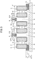
- an attaching structure in which three reactors 1A, 1B and 1C are arranged in series and fixed to a component fixing surface 12a of a case 12 of an AC/DC converter, and the attachment structure includes a placing member 40, a pressing member 41, two pressing force imparting portions 42 and 42, and heat transfer cushioning members 30 and 31 sandwiched between the component fixing surface 12a and lower surfaces of the reactors 1A and 1C.
- the placing member 40 is made of an insulating material such as a synthetic resin, and includes a receiving portion 43 that extends between positions to close lower openings of hollow portions 1a and 1c of the reactors 1A and 1C of both ends in the three arranged reactors 1A to 1C and receives the whole region of a lower surface of the reactor 1B and parts of the lower surfaces of the reactors 1A and 1C, a fixing portion (not illustrated) that fixes the receiving portion 43 to the component fixing surface 12a, positioning portions 44 to 46 which project from an upper surface of the receiving portion 43 and are inserted into the lower opening of the hollow portions 1a to 1c of the three reactors 1A to 1C, respectively, wall portions 47 and 48 each of which rises from a portion of the receiving portion 43 corresponding to an interval of the location where three reactors 1A to 1C are disposed, and coupling pillars 49 and 50 which project from upper portions of the wall portions 47 and 48. Further, in each of top portions of the coupling pillars 49 and 50, there is embedded a metal
- the pressing member 41 is also made of an insulating material such as a synthetic resin, and includes a pressing portion 51 that uniformly abuts on upper surfaces of the three reactors 1A to 1C, positioning portions 52 to 54 which project from a lower surface of the pressing portion 51 and are inserted into upper openings of the hollow portions 1a to 1c of the three reactors 1A to 1C, respectively, and engaging concave portions 55 and 56 formed so that central portions of the pressing portion 51 between the positioning portions 52 to 54 expand upwardly. Further, in top plates 57 and 58 of the engaging concave portions 55 and 56, screw through holes are formed, and external thread portions 28a of coupling screws 28 are inserted into the screw through holes from the upside of the holes.
- the two pressing force imparting portions 42 and 42 of the present embodiment include the external thread portions 28a of the coupling screws 28 disposed to engage with the two engaging concave portions 55 and 56 of the pressing member 41, and the internal thread portions 22a disposed in the top portions of the two coupling pillars 49 and 50 of the placing member 40 so that the external thread portions 28a are screwed into the internal thread portions.
- the heat transfer cushioning members 30 and 31 of the present embodiment are disposed on the component fixing surface 12a while surrounding a periphery of the receiving portion 43 of the placing member 40, and similarly to the first embodiment, a thickness t1 of the heat transfer cushioning members 30 and 31 is set to be larger than a plate thickness t2 of the receiving portion 43 on which the lower surfaces of the reactors 1A and 1C are disposed (t1 > t2).
- the two pressing force imparting portions 42 and 42 increase the distance between the placing member 40 and the pressing member 41, and when the height dimension H of the reactors 1A to 1C is low, the pressing force imparting portions 42 and 42 decrease the distance between the placing member 40 and the pressing member 41, whereby the three reactors 1A to 1C can be fixed to the case 12 with an optimum pressing force. Therefore, also in the present embodiment, the three reactors 1A to 1C for use as power conversion control units of a power conversion device mounted in a hybrid car or an electric car can securely be fixed to the case 12 by improving vibration resistant characteristics.
- the heat transfer cushioning members 30 and 31 are sandwiched in the compressed state between the lower surfaces of the reactors 1A and 1C which are not placed on the receiving portion 43 of the placing member 40 and the component fixing surface 12a, so that a vibration transmitted to the case 12 is easy to be absorbed by the heat transfer cushioning members 30 and 31, and the vibration resistant characteristics can further improve.
- the heat transfer cushioning members 30 and 31 are brought into contact closely with the reactors 1A and 1C and the case 12 so that a heat transfer area between each reactor and the case increases, and hence the heat generated by the reactors 1A and 1B is transferred to the case 12 via the heat transfer cushioning members 30 and 31 and then radiated. Therefore, it is possible to efficiently cool the reactors 1A to 1C.
- the placing member 40 and the heat transfer cushioning members 30 and 31, which are made of the insulating material, are disposed between the case 12 and coils 3 of the reactors 1A to 1C, and hence an insulating distance can sufficiently be acquired between the case 12 and each coil 3.
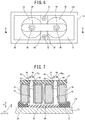
- FIG. 6 and FIG. 7 illustrate a winding component attachment structure of a third embodiment according to the present invention
- FIG. 6 is a plan view
- FIG. 7 is a view from an arrow direction of the VII-VII line of FIG. 6 .
- an attachment structure in which two reactors 1A and 1B are arranged in parallel and fixed to a component fixing surface 12a of a case 12 of an AC/DC converter, and the attachment structure includes a placing member 60 on which parts of lower surfaces of two reactors 1A and 1B are placed, a pressing member 61 disposed to abut on upper surfaces of the two reactors 1A and 1B, pressing force imparting portions 62 and 62 which impart, from the pressing member 14 to the two reactors 1A and 1B, a downward pressing force toward the component fixing surface 12a, and heat transfer cushioning members 30 and 31 sandwiched between the component fixing surface 12a and the lower surfaces of the reactors 1A and 1B.
- the placing member 60 is made of an insulating material such as a synthetic resin, and as illustrated in FIG. 7 , the placing member includes a receiving portion 63 that extends between positions to close lower openings of hollow portions 1a and 1b of the two reactors 1A and 1B arranged in parallel, to receive the parts of the lower surfaces of the reactors 1A and 1B, a fixing portion 64 that extends to the receiving portion 63 in the form of a cross (see FIG.
- the pressing member 61 is made of an insulating material such as a synthetic resin, and as illustrated in FIG. 7 , the pressing member is a plate-shaped member that uniformly abuts on the upper surfaces of the two reactors 1A and 1B, and there are formed two inserting holes 67 and 68 through which the positioning coupling pillars 65 and 66 mentioned above pass.
- the heat transfer cushioning members 30 and 31 are disposed on the component fixing surface 12a while surrounding a periphery of the receiving portion 63 of the placing member 60, and a thickness t1 of the heat transfer cushioning members 30 and 31 is set to be larger than a plate thickness t2 of the receiving portion 63 of the placing member 60 (t1 > t2).
- the fixing portion 64 of the placing member 60 is fixed to the component fixing surface 12a by use of fixing screws 32. Further, the heat transfer cushioning members 30 and 31 having the thickness t1 are disposed on the component fixing surface 12a while surrounding the periphery of the receiving portion 63 of the placing member 60.
- the two reactors 1A and 1B are disposed in a state where the positioning coupling pillars 65 and 66 of the placing member 60 are inserted into the hollow portions 1a and 1b.
- the positioning coupling pillars 65 and 66 projected from the hollow portions 1a and 1b of the two reactors 1A and 1B are inserted into the two inserting holes 67 and 68 of the pressing member 61, and nuts 69 and 70 are screwed into external thread portions 65a and 66a of the positioning coupling pillars 65 and 66 projected from the pressing member 61, respectively.
- the pressing force imparting portions 62 and 62 of the present embodiment include the external thread portions 65a and 66a of the positioning coupling pillars 65 and 66 and the nuts 69 and 70.
- the two reactors 1A and 1B when a height dimension H of the two reactors 1A and 1B is high, the pressing force imparting portions 62 and 62 increase the distance between the pressing member 61 and the placing member 60, and when the height dimension H of the reactors 1A and 1B is low, the pressing force imparting portions 62 and 62 decrease the distance between the pressing member 61 and the placing member 60, thereby fixing the reactors 1A and 1B to the case 12 with an optimum pressing force. Therefore, also in the present embodiment, the two reactors 1A and 1B for use as power conversion control units of a power conversion device mounted in a hybrid car or an electric car can securely be fixed to the case 12 by improving vibration resistant characteristics.
- the heat transfer cushioning members 30 and 31 are sandwiched in the compressed state between the lower surfaces of the reactors 1A and 1B which are not placed on the receiving portion 63 of the placing member 60 and the component fixing surface 12a, so that a vibration transmitted to the case 12 is easy to be absorbed by the heat transfer cushioning members 30 and 31, and the vibration resistant characteristics can further improve.
- the heat transfer cushioning members 30 and 31 are brought into contact closely with the reactors 1A and 1B and the case 12 so that a heat transfer area between each reactor and the case increases, and hence the heat generated by the reactors 1A and 1B is transferred to the case 12 via the heat transfer cushioning members 30 and 31 and radiated. Therefore, even when the amount of the heat to be generated by the reactors 1A and 1B is large, it is possible to efficiently cool the reactors 1A and 1B.
- the placing member 60 and the heat transfer cushioning members 30 and 31, which are made of the insulating material, are disposed between the case 12 and coils 3 of the reactors 1A and 1B, and hence an insulating distance can sufficiently be acquired between the case 12 and each coil 3.
- the positioning coupling pillars 65 and 66 of the placing member 60 function as positioning members of the hollow portions 1a and 1b of the two reactors 1A and 1B and as fixing members of the pressing member 61, and hence simplification of the reactor attachment structure can be achieved.
- FIG. 8 illustrates a winding component attachment structure of a fourth embodiment according to the present invention, and by the attachment structure, three reactors 1A, 1 Band 1C are arranged in series and fixed.
- the attachment structure includes a placing member 75 on which three positioning coupling pillars 72 to 74 rise from a receiving portion 71, a pressing member 79 in which three inserting holes 76 to 78 are formed so that the positioning coupling pillars 72 to 74 pass therethrough, nuts 80, 81 and 82 which pass through the inserting holes 76 to 78 to be screwed into external thread portions 72a, 73a and 74a of the positioning coupling pillars 72 to 74 extended to an upper portion of the pressing member 79, and heat transfer cushioning members 30 and 31 sandwiched between a component fixing surface 12a and lower surfaces of the reactors 1A and 1C.
- a pressing force imparting portion includes the external thread portions 72a, 73a and 74a of the positioning coupling pillars 72 to 74, and the nuts 80, 81 and 82.
- the three reactors 1A to 1C for use as power conversion control units of a power conversion device mounted in a hybrid car or an electric car can securely be fixed to a case 12 by improving vibration resistant characteristics.
- the heat transfer cushioning members 30 and 31 are sandwiched in a compressed state between the lower surfaces of the reactors 1A and 1C which are not placed on the receiving portion 71 of the placing member 75 and the component fixing surface 12a, so that a vibration transmitted to the case 12 is easy to be absorbed by the heat transfer cushioning members 30 and 31, and the vibration resistant characteristics can further improve.
- the heat transfer cushioning members 30 and 31 are brought into contact closely with the reactors 1A and 1C and the case 12 so that a heat transfer area between each reactor and the case increases, and hence the heat generated by the reactors 1A and 1B is transferred to the case 12 via the heat transfer cushioning members 30 and 31 and then radiated. Therefore, it is possible to efficiently cool the reactors 1A to 1C.
- the three positioning coupling pillars 72 to 74 of the placing member 75 function as positioning members of hollow portions 1a, 1b and 1c of the three reactors 1A to 1C and as fixing members of the pressing member 79, and hence simplification of the reactor attachment structure can be achieved.
- FIG. 9 and FIG. 10 illustrate a winding component attachment structure of a fifth embodiment according to the present invention
- FIG. 9 is a plan view
- FIG. 10 is a view from an arrow direction of the X-X line of FIG. 9 .
- an attachment structure in which one reactor 1A is fixed to a component fixing surface 12a of a case 12 of an AC/DC converter, and the attachment structure includes a placing member 85 on which a part of a lower surface of the reactor 1A is placed, a pressing member 86 disposed to abut on an upper surface of the reactor 1A, a pressing force imparting portion 87 that imparts, from the pressing member 86 to the reactor 1A, a downward pressing force toward a component fixing surface 12a, and heat transfer cushioning members 30 and 31 sandwiched between the component fixing surface 12a and the lower surface of the reactor 1A.
- the placing member 85 is made of an insulating material such as a synthetic resin, and includes a receiving portion 88 that receives a lower surface central side of the reactor 1A, a fixing portion 89 that extends perpendicularly to a plane direction of the receiving portion 88, and a positioning coupling pillar 90 that projects from an upper surface of the receiving portion 89 and is inserted from a lower opening of a hollow portion 1a of the reactor 1A close to an upper opening thereof, and in a top portion of the positioning coupling pillar 90, there is embedded a metal tube 91 in which an internal thread portion 91a is formed in an inner peripheral surface. Additionally, the fixing portion 89 of the placing member 85 is fixed to the component fixing surface 12a via fixing screws 92.
- the pressing member 86 is also a plate member made of an insulating material such as a synthetic resin, a screw through hole 86a is formed in a central portion of the pressing member 86, and a cylindrical insulating portion 86b is formed to project from a lower surface position as a concentric circle position in the screw through hole 86a. Further, an external thread portion 93a of a coupling screw 93 is inserted from the upside into the screw through hole 86a of the pressing member 86.
- the pressing force imparting portion 87 of the present embodiment includes the external thread portion 93a of the coupling screw 93 inserted into the screw through hole 86a of the pressing member 86, and the internal thread portion 91a disposed in the top portion of the positioning coupling pillar 90 of the placing member 85 so that the external thread portion 93a is screwed into the internal thread portion.
- the fixing portion 89 of the placing member 85 is fixed to the component fixing surface 12a by use of the fixing screws 92. Further, the heat transfer cushioning members 30 and 31 having a thickness t1 are disposed on the component fixing surface 12a while surrounding a periphery of the receiving portion 89 of the placing member 85.
- the reactor 1A is disposed in a state where the positioning coupling pillar 90 of the placing member 85 is inserted into the hollow portion 1a.
- the external thread portion 93a of the coupling screw 93 of the pressing member 86 and the cylindrical insulating portion 86b are inserted into the hollow portion 1a of the reactor 1A. Further, the external thread portion 93a of the coupling screw 93 is screwed into the internal thread portion 91a while surrounding an upper portion outer periphery of the positioning coupling pillar 90 with the cylindrical insulating portion 86b.
- a screwed state of the internal thread portion 91a of the positioning coupling pillar 90 and the external thread portion 93a of the coupling screw 93 is adjusted, and a distance between the pressing member 86 and the placing member 85 is set to a predetermined value, thereby fixing the reactor 1A in a state of being pressed toward a case 12.
- the heat transfer cushioning members 30 and 31, which abut on the lower surface of the reactor 1A to be sandwiched between the lower surface and the component fixing surface 12a are compressed down to a thickness equal to a plate thickness t2 of the receiving portion 88 of the placing member 85.
- the one reactor 1A for use as a power conversion control unit of a power conversion device mounted in a hybrid car or an electric car can securely be fixed to the case 12 by improving vibration resistant characteristics.
- the heat transfer cushioning members 30 and 31 are sandwiched in a compressed state between the lower surface of the reactor 1A which is not placed on the receiving portion 88 of the placing member 85 and the component fixing surface 12a, so that a vibration transmitted to the case 12 is easy to be absorbed by the heat transfer cushioning members 30 and 31, and the vibration resistant characteristics can further improve.
- the heat transfer cushioning members 30 and 31 are brought into contact closely with the reactor 1A and the case 12 so that a heat transfer area between the reactor and the case increases, and hence the heat generated by the reactor 1A is transferred to the case 12 via the heat transfer cushioning members 30 and 31 and radiated. Therefore, even when the amount of the heat to be generated by the reactor 1A is large, it is possible to efficiently cool the reactor 1A.
- an outer periphery of the pressing force imparting portion 87 (a portion in which the external thread portion 93 a of the coupling screw 93 is screwed into the internal thread portion 91 a of the metal tube 91 of the positioning coupling pillar 90) is surrounded with the cylindrical insulating portion 86b made of an insulator, and hence an insulating distance between the coupling screw 93 and the metal tube 91 and a coil 3 of the reactor 1A can sufficiently be acquired.
- FIG. 11 and FIG. 12 illustrate a winding component attachment structure of a sixth embodiment according to the present invention
- FIG. 11 is a plan view
- FIG. 12 is a view from an arrow direction of the XII-XII line of FIG. 11 .
- an attachment structure in which one reactor 1A is fixed to a component fixing surface 12a of a case 12 of an AC/DC converter in the same manner as in the fifth embodiment illustrated in FIG. 9 and FIG. 10 .
- the attachment structure includes a placing member 97 on which one positioning coupling pillar 96 rises from a receiving portion 95, a pressing member 99 in which an inserting hole 98 is formed so that the positioning coupling pillar 96 passes therethrough, a nut 100 screwed into an external thread portion 96a of the positioning coupling pillar 96 that passes through the inserting hole 98 to be extended to an upper portion of the pressing member 99, and heat transfer cushioning members 30 and 31 sandwiched between the component fixing surface 12a and a lower surface of the reactor 1A, 1C.
- a pressing force imparting portion includes the external thread portion 96a of the positioning coupling pillar 96, and the nut 100.
- the one reactor 1A for use as a power conversion control unit of a power conversion device mounted in a hybrid car or an electric car can securely be fixed to the case 12 by improving vibration resistant characteristics in the same manner as in the fifth embodiment.
- the heat transfer cushioning members 30 and 31 are sandwiched in a compressed state between the lower surface of the reactor 1A which is not placed on the receiving portion 95 of the placing member 97 and the component fixing surface 12a, so that a vibration transmitted to the case 12 is easy to be absorbed by the heat transfer cushioning members 30 and 31, and the vibration resistant characteristics can further improve.
- the heat transfer cushioning members 30 and 31 are brought into contact closely with the reactor 1A and the case 12 so that a heat transfer area between the reactor and the case increases, and hence the heat generated by the reactor 1A is transferred to the case 12 via the heat transfer cushioning members 30 and 31 and then radiated. Therefore, it is possible to efficiently cool the reactor 1A.
- the positioning coupling pillar 96 of the placing member 97 functions as a positioning member of a hollow portion 1a of the reactor 1A and as a fixing member of the pressing member 99, and hence simplification of the reactor attachment structure can be achieved.
- a winding component attachment structure according to the present invention and a power conversion device provided with this attachment structure are useful in securely fixing, to a case, a winding component such as a reactor having a different outer shape dimension for each product, by improving vibration resistant characteristics even when the winding component is mounted in a hybrid car, an electric car or the like.
- 1A, 1B, and 1C ⁇ reactor 1a, 1b and 1c ⁇ hollow portion, 2 ⁇ core, 3 ⁇ coil, 12 ⁇ case, 12a ⁇ component fixing surface, 12b ⁇ screw hole, 13 ⁇ placing member, 14 ⁇ pressing member, 15 ⁇ pressing force imparting portion, 16 ⁇ receiving portion, 17 ⁇ fixing portion, 17a ⁇ through hole, 18 and 19 ⁇ positioning portion, 20 ⁇ wall portion, 21 ⁇ coupling pillar, 22 ⁇ metal tube, 22a ⁇ internal thread portion, 23 ⁇ pressing portion, 24 and 25 ⁇ positioning portion, 26 ⁇ engaging concave portion, 27 ⁇ top plate, 27a ⁇ through hole, 28a ⁇ external thread portion, 30 and 31 ⁇ heat transfer cushioning member, 40 ⁇ placing member, 41 ⁇ pressing member, 42 ⁇ pressing force imparting portion, 43 ⁇ receiving portion, 44 to 46 ⁇ positioning portion, 47 and 48 ⁇ wall portion, 49 and 50 ⁇ coupling pillar, 51 ⁇ pressing portion, 52 to 54 ⁇ positioning portion, 55
Landscapes
- Engineering & Computer Science (AREA)
- Power Engineering (AREA)
- Housings And Mounting Of Transformers (AREA)
- Electric Propulsion And Braking For Vehicles (AREA)
- Life Sciences & Earth Sciences (AREA)
- Sustainable Development (AREA)
- Sustainable Energy (AREA)
- Transportation (AREA)
- Mechanical Engineering (AREA)
Abstract
Description
- The present invention relates to a winding component attachment structure to fix a winding component such as a reactor to a case, and a power conversion device provided with this attachment structure.
- In a power conversion device such as an AC/DC converter mounted in a hybrid car, an electric car or the like, it is general that a winding component such as a reactor is disposed in a case and the winding component is fixed to the case. In this winding component attachment structure, the winding component has a comparatively large weight, and hence it is required that a vibration resistance after fixing the winding component to the case is excellent.
- The reactor is a component including a ring-shaped core, and a coil alternately wound around and along an inner peripheral surface and an outer peripheral surface of this core.
- As the attachment structure in which the reactor is attached to the case, for example, a structure described in
Patent Literature 1 is known. - In the attachment structure of the reactor of
Patent Literature 1, the reactor is disposed on an upper surface of the case, and at least two leaf spring attaching portions are disposed on the upper surface of the case to sandwich the reactor therebetween. Further, a leaf spring is disposed to cover an upper portion of the reactor, and both end portions of the leaf spring are attached to the leaf spring attaching portions to generate a spring force in the leaf spring, whereby the reactor is fixed while pressing the reactor toward the case with this leaf spring. - PTL 1:
JP 2007-227640 A - Additionally, during preparation of a reactor, bend R is generated when bending a coil along corner portions of an upper surface and a lower surface of a core, and hence clearances are generated between the coil and each of the upper surface, the lower surface and an outer periphery of the core, thereby preparing the reactors having variable outer shape dimensions (a height dimension and an outer diameter dimension) for each product.
- Here, when the reactor having a small outer shape dimension is fixed by an attachment structure of
Patent Literature 1, a spring force of a leaf spring that presses the reactor weakens, and the reactor might be detached from the case by a vibration input. - Additionally, when the reactor having a large outer shape dimension is fixed by the attachment structure of
Patent Literature 1, the spring force of the leaf spring excessively increases, so that the increased spring force might impart damage to the leaf spring and the reactor. - Therefore, the present invention has been developed to solve these problems, and objects thereof are to provide a winding component attachment structure in which a winding component such as a reactor having a different outer shape dimension for each product can securely be fixed to a case by improving vibration resistant characteristics even when the winding component is mounted in a hybrid car, an electric car or the like, and to provide a power conversion device provided with this attachment structure.
- To achieve the above objects, a winding component attachment structure according to one aspect of the present invention is a winding component attachment structure in which a winding component is fixed to a case, which is formed by winding a coil around and along an inner peripheral surface and an outer peripheral surface of a ring-shaped core a plurality of times, the attachment structure includes a placing member made of an insulating material and fixed to a fixing surface of the case in a state where a lower surface of the winding component is placed, a pressing member made of an insulating material and disposed to abut on an upper surface of the winding component, and a pressing force imparting portion that couples the placing member with the pressing member and imparts a pressing force toward the fixing surface, from the pressing member to the winding component, and in the pressing force imparting portion, a distance between the placing member and the pressing member is variable in accordance with a height change of the winding component.
- Additionally, in the winding component attachment structure according to the one aspect of the present invention, it is preferable that the pressing force imparting portion includes an external thread portion disposed in one of the placing member and the pressing member to extend toward the other member, and an internal thread portion disposed in the other member of the placing member and the pressing member and screwed into the one external thread portion; and a distance between the placing member and the pressing member is variable by changing a screwing position of the external thread portion into the internal thread portion.
- In addition, in the winding component attachment structure according to the one aspect of the present invention, it is preferable that the placing member includes a lower positioning portion that projects upward to be inserted into a hollow portion of the winding component from a lower opening thereof, and the pressing member includes an upper positioning portion that projects downward to be inserted into the hollow portion of the winding component from an upper opening thereof.
- Additionally, in the winding component attachment structure according to the one aspect of the present invention, it is preferable that at least two winding components are disposed in the form of a row on the placing member, and the pressing force imparting portion is disposed between the two adjacent winding components.
- In addition, in the winding component attachment structure according to the one aspect of the present invention, it is preferable that the pressing force imparting portion has a function of positioning the winding component by passing through the hollow portion of the winding component.
- Additionally, in the winding component attachment structure according to the one aspect of the present invention, it is preferable that a part of the lower surface of the winding component is placed on the placing member, and the winding component is pressed and fixed to a side of the fixing surface in a state where a cushioning material that absorbs a vibration transmitted to the case is sandwiched between the residual part of the lower surface of the winding component and the fixing surface.
- Furthermore, in the winding component attachment structure according to the one aspect of the present invention, it is preferable that the cushioning material is a member excellent in thermal conductivity.
- Additionally, a power conversion device according to the present invention is provided with the above winding component attachment structure.
- According to a winding component attachment structure of the present invention and a power conversion device provided with this attachment structure, a winding component such as a reactor having a different outer shape dimension for each product can securely be fixed to a case by improving vibration resistant characteristics even when the winding component is mounted in a hybrid car, an electric car or the like.
-
-
FIGS. 1A and 1B are views illustrative of a winding component such as a reactor according to the present invention; -
FIG. 2 is a plan view illustrative of a winding component attachment structure of a first embodiment according to the present invention; -
FIG. 3 is a view from an arrow direction of the II-II line ofFIG. 2 ; -
FIG. 4 is a view from an arrow direction of the III-III line ofFIG. 2 ; -
FIG. 5 is a view illustrative of a winding component attachment structure of a second embodiment according to the present invention; -
FIG. 6 is a plan view illustrative of a winding component attachment structure of a third embodiment according to the present invention; -
FIG. 7 is a view from an arrow direction of the VII-VII line ofFIG. 6 ; -
FIG. 8 is a view illustrative of a winding component attachment structure of a fourth embodiment according to the present invention; -
FIG. 9 is a plan view illustrative of a winding component attachment structure of a fifth embodiment according to the present invention; -
FIG. 10 is a view from an arrow direction of the X-X line ofFIG. 9 ; -
FIG. 11 is a plan view illustrative of a winding component attachment structure of a sixth embodiment according to the present invention; and -
FIG. 12 is a view from an arrow direction of the XII-XII line ofFIG. 11 . - Modes to carry out the present invention (hereinafter referred to as embodiments) will now be described in detail with reference to the drawings.
-
FIGS. 1A and 1B illustrate areactor 1 as a winding component according to the present invention. Thereactor 1 is a component including a ring-shaped core 2, and acoil 3 alternately wound around and along an inner peripheral surface and an outer peripheral surface of thecore 2 a plurality of times. - During preparation of the
reactor 1, as illustrated inFIG. 1B ,bending radius portions 4 to 7 are generated when bending thecoil 3 along corner portions on an inner diameter side and an outer diameter side of anupper surface 2a and a lower surface 2b of thecore 2, and henceclearances 8 to 11 are generated between the coil and each of the upper surface, an inner periphery, the lower surface and an outer periphery of thecore 2. Consequently, in the preparedreactor 1, an outer shape dimension (a height dimension H or an outer diameter dimension D) varies for each product. - The
reactor 1 is mounted in a case, as a power conversion control unit of an AC/DC converter for a hybrid car or an electric car. -
FIG. 2 to FIG. 4 illustrate a winding component attachment structure of a first embodiment according to the present invention.FIG. 2 is a plan view illustrative of the winding component attachment structure,FIG. 3 is a view from an arrow direction of the II-II line ofFIG. 2 , andFIG. 4 is a view from an arrow direction of the III-III line ofFIG. 2 . - According to the present embodiment, there is provided an attachment structure of two
reactors component fixing surface 12a of acase 12 of an AC/DC converter, and the attachment structure includes a placingmember 13 on which parts of lower surfaces of the tworeactors member 14 disposed to abut on upper surfaces of the tworeactors force imparting portion 15 that imparts, from the pressingmember 14 to the tworeactors component fixing surface 12a, and heattransfer cushioning members component fixing surface 12a and the lower surfaces of thereactors - The placing
member 13 is made of an insulating material such as a synthetic resin, and as illustrated inFIG. 3 , the placing member includes a receivingportion 16 that extends between positions to close lower openings ofhollow portions reactors reactors fixing portion 17 that extends to thereceiving portion 16 in the form of a cross (seeFIG. 2 ), positioningportions receiving portion 16 and are inserted into the lower openings of thehollow portions reactors wall portion 20 that rises from a central portion of the upper surface of thereceiving portion 16 between positions where the tworeactors coupling pillar 21 that projects from an upper portion (seeFIG. 4 ) of thewall portion 20. - Further, in a top portion of the
coupling pillar 21, there is embedded ametal tube 22 in which aninternal thread portion 22a is formed in an inner peripheral surface. - As illustrated in
FIG. 4 , screw throughholes 17a are formed in thefixing portion 17, and fixingscrews 32 inserted into the screw throughholes 17a are screwed from thecomponent fixing surface 12a intoscrew holes 12b formed in thecase 12, whereby the placingmember 13 is fixed to thecomponent fixing surface 12a. - The pressing
member 14 is also made of an insulating material such as a synthetic resin, and as illustrated inFIG. 3 , the pressing member includes apressing portion 23 that uniformly abuts on the upper surfaces of the tworeactors portions pressing portion 23 and are inserted into upper openings of thehollow portions reactors concave portion 26 formed so that a central portion of thepressing portion 23 expands upwardly. In atop plate 27 in which the engagingconcave portion 26 is formed, a screw throughhole 27a is formed, and anexternal thread portion 28a of acoupling screw 28 is inserted into the screw throughhole 27a from the upside of the hole. - Here, the pressing
force imparting portion 15 of the present embodiment includes theexternal thread portion 28a of thecoupling screw 28 disposed to engage in the engagingconcave portion 26 of thepressing member 14, and theinternal thread portion 22a disposed in the top portion of thecoupling pillar 21 of the placingmember 13 so that theexternal thread portion 28a is screwed into the internal thread portion. Additionally, lower positioning portions according to the present invention correspond to thepositioning portions positioning portions - Additionally, the heat
transfer cushioning members FIG. 2 and FIG. 3 , the heat transfer cushioning members are disposed on thecomponent fixing surface 12a while surrounding a periphery of the receivingportion 16 of the placingmember 13. - A thickness t1 of the heat
transfer cushioning members portion 16 of the placingmember 13 on which the lower surfaces of thereactors - Next, there will be described a procedure of fixing the two
reactors component fixing surface 12a. - First, the screw through
holes 17a formed in thefixing portion 17 of the placingmember 13 are disposed to face thescrew holes 12b formed in thecase 12, and thefixing screws 32 inserted into the screw throughholes 17a are screwed into thescrew holes 12b, thereby fixing the placingmember 13 to thecomponent fixing surface 12a. - Additionally, the heat
transfer cushioning members component fixing surface 12a while surrounding the periphery of the receivingportion 16 of the placingmember 13. - Next, the positioning
portion 18 of the placingmember 13 is inserted into the lower opening of thehollow portion 1a of onereactor 1A, and a part of the lower surface of thereactor 1A is placed on the heattransfer cushioning member 30 disposed on apositioning portion 18 side of the placingmember 13. Additionally, the positioningportion 19 of the placingmember 13 is inserted into the lower opening of thehollow portion 1b of theother reactor 1B, and a part of the lower surface of thereactor 1B is placed on the heattransfer cushioning member 31 disposed on apositioning portion 19 side of the placingmember 13. - Next, the pressing
member 14 is disposed on the upper surfaces of thereactors positioning portions hollow portions reactors member 13. - Next, the
coupling screw 28 constituting the pressingforce imparting portion 15 is inserted downwardly through the throughhole 27a formed in the engagingconcave portion 26 of the pressingmember 14, and theexternal thread portion 28a of thecoupling screw 28 is screwed into theinternal thread portion 22a disposed in the top portion of thecoupling pillar 21 of the placingmember 13. - Further, a screwed state of the
external thread portion 28a of thecoupling screw 28 and theinternal thread portion 22a of the placingmember 13 is adjusted, and a distance between the pressingmember 14 and the placingmember 13 is set to a predetermined value, thereby fixing the tworeactors case 12. At this time, the heattransfer cushioning members reactors component fixing surface 12a, are compressed down to a thickness equal to the plate thickness t2 of the receivingportion 16 of the placingmember 13 as illustrated inFIG. 3 . - Next, effects of the present embodiment will be described.
- According to the attachment structure of the reactors of the present embodiment, even the
reactors case 12, because the distance between the placingmember 13 and the pressingmember 14 is variable in accordance with a height change of each of thereactors - That is, when a height dimension H of the two
reactors force imparting portion 15 increases the distance between the placingmember 13 and the pressingmember 14, and when the height dimension H of thereactors force imparting portion 15 decreases the distance between the placingmember 13 and the pressingmember 14, thereby fixing thereactors case 12 with an optimum pressing force. Therefore, in the present embodiment, the tworeactors case 12 by improving the vibration resistant characteristics. - Additionally, the heat
transfer cushioning members reactors portion 16 of the placingmember 13 and thecomponent fixing surface 12a, so that a vibration transmitted to thecase 12 is easy to be absorbed by the heattransfer cushioning members - In addition, also when an amount of heat to be generated by the
reactors transfer cushioning members reactors case 12 so that a heat transfer area between each reactor and the case increases, and hence the heat generated by thereactors case 12 via the heattransfer cushioning members reactors reactors - Additionally, in the present embodiment, the placing
member 13 and the heattransfer cushioning members case 12 and thecoils 3 of thereactors case 12 and thecoil 3. - In addition, only by inserting the
positioning portions member 13 and thepositioning portions member 14 into thehollow portions reactors reactors member 13 and the pressingmember 14 is completed, and hence an attaching operation of thereactors - Furthermore, in the pressing
force imparting portion 15 of the present embodiment, the distance between the pressingmember 14 and the placingmember 13 can be varied by adjusting a screwing length of theexternal thread portion 28a of thecoupling screw 28 into theinternal thread portion 22a of the placingmember 13, and hence simplification of the reactor attachment structure can be achieved. - Next,
FIG. 5 illustrates a winding component attachment structure of a second embodiment according to the present invention. It is to be noted that a constitution similar to the first embodiment is denoted with the same reference signs and the description is omitted. - According to the present embodiment, there is provided an attaching structure in which three
reactors component fixing surface 12a of acase 12 of an AC/DC converter, and the attachment structure includes a placingmember 40, a pressingmember 41, two pressingforce imparting portions transfer cushioning members component fixing surface 12a and lower surfaces of thereactors - The placing
member 40 is made of an insulating material such as a synthetic resin, and includes a receivingportion 43 that extends between positions to close lower openings ofhollow portions reactors reactors 1A to 1C and receives the whole region of a lower surface of thereactor 1B and parts of the lower surfaces of thereactors portion 43 to thecomponent fixing surface 12a,positioning portions 44 to 46 which project from an upper surface of the receivingportion 43 and are inserted into the lower opening of thehollow portions 1a to 1c of the threereactors 1A to 1C, respectively,wall portions portion 43 corresponding to an interval of the location where threereactors 1A to 1C are disposed, andcoupling pillars wall portions coupling pillars metal tube 22 in which aninternal thread portion 22a is formed in an inner peripheral surface. - The pressing
member 41 is also made of an insulating material such as a synthetic resin, and includes apressing portion 51 that uniformly abuts on upper surfaces of the threereactors 1A to 1C,positioning portions 52 to 54 which project from a lower surface of thepressing portion 51 and are inserted into upper openings of thehollow portions 1a to 1c of the threereactors 1A to 1C, respectively, and engagingconcave portions pressing portion 51 between the positioningportions 52 to 54 expand upwardly. Further, intop plates concave portions external thread portions 28a of coupling screws 28 are inserted into the screw through holes from the upside of the holes. - Here, the two pressing
force imparting portions external thread portions 28a of the coupling screws 28 disposed to engage with the two engagingconcave portions member 41, and theinternal thread portions 22a disposed in the top portions of the twocoupling pillars member 40 so that theexternal thread portions 28a are screwed into the internal thread portions. - Additionally, the heat
transfer cushioning members component fixing surface 12a while surrounding a periphery of the receivingportion 43 of the placingmember 40, and similarly to the first embodiment, a thickness t1 of the heattransfer cushioning members portion 43 on which the lower surfaces of thereactors - Further, when screwed states of the
external thread portions 28a of the coupling screws 28 of the two pressingforce imparting portions internal thread portions 22a of the placingmember 40 are adjusted and a distance between the pressingmember 41 and the placingmember 40 is set to a predetermined value to fix the threereactors 1A to 1C in a state of being pressed toward thecase 12, the heattransfer cushioning members reactors component fixing surface 12a, are compressed down to a thickness equal to the plate thickness t2 of the receivingportion 43 of the placingmember 40. - According to the attachment structure of the reactors of the present embodiment, when a height dimension H of the three
reactors 1A to 1C is high, the two pressingforce imparting portions member 40 and the pressingmember 41, and when the height dimension H of thereactors 1A to 1C is low, the pressingforce imparting portions member 40 and the pressingmember 41, whereby the threereactors 1A to 1C can be fixed to thecase 12 with an optimum pressing force. Therefore, also in the present embodiment, the threereactors 1A to 1C for use as power conversion control units of a power conversion device mounted in a hybrid car or an electric car can securely be fixed to thecase 12 by improving vibration resistant characteristics. - Additionally, the heat
transfer cushioning members reactors portion 43 of the placingmember 40 and thecomponent fixing surface 12a, so that a vibration transmitted to thecase 12 is easy to be absorbed by the heattransfer cushioning members - In addition, also when an amount of heat to be generated by the
reactors 1A to 1C is large, the heattransfer cushioning members reactors case 12 so that a heat transfer area between each reactor and the case increases, and hence the heat generated by thereactors case 12 via the heattransfer cushioning members reactors 1A to 1C. - Additionally, also in the present embodiment, the placing
member 40 and the heattransfer cushioning members case 12 andcoils 3 of thereactors 1A to 1C, and hence an insulating distance can sufficiently be acquired between thecase 12 and eachcoil 3. - Additionally, only by inserting the
positioning portions 44 to 46 of the placingmember 40 and thepositioning portions 52 to 54 of the pressingmember 41 into thehollow portions 1a to 1c of the threereactors 1A to 1C, positioning of thereactors 1A to 1C to the placingmember 40 and the pressingmember 41 is completed, and hence an attaching operation of thereactors 1A to 1C can easily be performed. - Next,
FIG. 6 and FIG. 7 illustrate a winding component attachment structure of a third embodiment according to the present invention,FIG. 6 is a plan view, andFIG. 7 is a view from an arrow direction of the VII-VII line ofFIG. 6 . - According to the present embodiment, there is provided an attachment structure in which two
reactors component fixing surface 12a of acase 12 of an AC/DC converter, and the attachment structure includes a placingmember 60 on which parts of lower surfaces of tworeactors member 61 disposed to abut on upper surfaces of the tworeactors force imparting portions member 14 to the tworeactors component fixing surface 12a, and heattransfer cushioning members component fixing surface 12a and the lower surfaces of thereactors - The placing
member 60 is made of an insulating material such as a synthetic resin, and as illustrated inFIG. 7 , the placing member includes a receivingportion 63 that extends between positions to close lower openings ofhollow portions reactors reactors portion 64 that extends to the receivingportion 63 in the form of a cross (seeFIG. 6 ), and twopositioning coupling pillars portion 63 and extend through thehollow portions reactors positioning coupling pillars external thread portions - The pressing
member 61 is made of an insulating material such as a synthetic resin, and as illustrated inFIG. 7 , the pressing member is a plate-shaped member that uniformly abuts on the upper surfaces of the tworeactors holes positioning coupling pillars - Additionally, the heat
transfer cushioning members component fixing surface 12a while surrounding a periphery of the receivingportion 63 of the placingmember 60, and a thickness t1 of the heattransfer cushioning members portion 63 of the placing member 60 (t1 > t2). - Next, in the present embodiment, there will be described a procedure of fixing the two
reactors component fixing surface 12a. - First, the fixing
portion 64 of the placingmember 60 is fixed to thecomponent fixing surface 12a by use of fixing screws 32. Further, the heattransfer cushioning members component fixing surface 12a while surrounding the periphery of the receivingportion 63 of the placingmember 60. - Next, the two
reactors positioning coupling pillars member 60 are inserted into thehollow portions - Next, the
positioning coupling pillars hollow portions reactors holes member 61, andnuts external thread portions positioning coupling pillars member 61, respectively. - Further, screwed states of the
external thread portions positioning coupling pillars member 61 and the placingmember 60 is set to a predetermined value, thereby fixing the tworeactors case 12. At this time, the heattransfer cushioning members reactors component fixing surface 12a, are compressed down to a thickness equal to the plate thickness t2 of the receivingportion 63 of the placingmember 60 as illustrated inFIG. 7 . - It is to be noted that the pressing
force imparting portions external thread portions positioning coupling pillars - According to the attachment structure of the reactors of the present embodiment, when a height dimension H of the two
reactors force imparting portions member 61 and the placingmember 60, and when the height dimension H of thereactors force imparting portions member 61 and the placingmember 60, thereby fixing thereactors case 12 with an optimum pressing force. Therefore, also in the present embodiment, the tworeactors case 12 by improving vibration resistant characteristics. - Additionally, the heat
transfer cushioning members reactors portion 63 of the placingmember 60 and thecomponent fixing surface 12a, so that a vibration transmitted to thecase 12 is easy to be absorbed by the heattransfer cushioning members - Additionally, also when an amount of heat to be generated by the
reactors transfer cushioning members reactors case 12 so that a heat transfer area between each reactor and the case increases, and hence the heat generated by thereactors case 12 via the heattransfer cushioning members reactors reactors - Additionally, in the present embodiment, the placing
member 60 and the heattransfer cushioning members case 12 andcoils 3 of thereactors case 12 and eachcoil 3. - In addition, the
positioning coupling pillars member 60 function as positioning members of thehollow portions reactors member 61, and hence simplification of the reactor attachment structure can be achieved. - Next,
FIG. 8 illustrates a winding component attachment structure of a fourth embodiment according to the present invention, and by the attachment structure, threereactors Band 1C are arranged in series and fixed. - In the present embodiment, the attachment structure includes a placing
member 75 on which threepositioning coupling pillars 72 to 74 rise from a receivingportion 71, a pressingmember 79 in which three insertingholes 76 to 78 are formed so that thepositioning coupling pillars 72 to 74 pass therethrough, nuts 80, 81 and 82 which pass through the insertingholes 76 to 78 to be screwed intoexternal thread portions positioning coupling pillars 72 to 74 extended to an upper portion of the pressingmember 79, and heattransfer cushioning members component fixing surface 12a and lower surfaces of thereactors - It is to be noted that a pressing force imparting portion according to the present invention includes the
external thread portions positioning coupling pillars 72 to 74, and the nuts 80, 81 and 82. - According to the attachment structure of the reactors of the present embodiment, similarly to the second embodiment, the three
reactors 1A to 1C for use as power conversion control units of a power conversion device mounted in a hybrid car or an electric car can securely be fixed to acase 12 by improving vibration resistant characteristics. - Additionally, the heat
transfer cushioning members reactors portion 71 of the placingmember 75 and thecomponent fixing surface 12a, so that a vibration transmitted to thecase 12 is easy to be absorbed by the heattransfer cushioning members - In addition, also when an amount of heat to be generated by the
reactors 1A to 1C is large, the heattransfer cushioning members reactors case 12 so that a heat transfer area between each reactor and the case increases, and hence the heat generated by thereactors case 12 via the heattransfer cushioning members reactors 1A to 1C. - Furthermore, the three
positioning coupling pillars 72 to 74 of the placingmember 75 function as positioning members ofhollow portions reactors 1A to 1C and as fixing members of the pressingmember 79, and hence simplification of the reactor attachment structure can be achieved. - Next,
FIG. 9 and FIG. 10 illustrate a winding component attachment structure of a fifth embodiment according to the present invention,FIG. 9 is a plan view, andFIG. 10 is a view from an arrow direction of the X-X line ofFIG. 9 . - According to the present embodiment, there is provided an attachment structure in which one
reactor 1A is fixed to acomponent fixing surface 12a of acase 12 of an AC/DC converter, and the attachment structure includes a placingmember 85 on which a part of a lower surface of thereactor 1A is placed, a pressingmember 86 disposed to abut on an upper surface of thereactor 1A, a pressing force imparting portion 87 that imparts, from the pressingmember 86 to thereactor 1A, a downward pressing force toward acomponent fixing surface 12a, and heattransfer cushioning members component fixing surface 12a and the lower surface of thereactor 1A. - The placing
member 85 is made of an insulating material such as a synthetic resin, and includes a receivingportion 88 that receives a lower surface central side of thereactor 1A, a fixingportion 89 that extends perpendicularly to a plane direction of the receivingportion 88, and apositioning coupling pillar 90 that projects from an upper surface of the receivingportion 89 and is inserted from a lower opening of ahollow portion 1a of thereactor 1A close to an upper opening thereof, and in a top portion of thepositioning coupling pillar 90, there is embedded ametal tube 91 in which aninternal thread portion 91a is formed in an inner peripheral surface. Additionally, the fixingportion 89 of the placingmember 85 is fixed to thecomponent fixing surface 12a via fixing screws 92. - The pressing
member 86 is also a plate member made of an insulating material such as a synthetic resin, a screw through hole 86a is formed in a central portion of the pressingmember 86, and a cylindrical insulatingportion 86b is formed to project from a lower surface position as a concentric circle position in the screw through hole 86a. Further, anexternal thread portion 93a of a coupling screw 93 is inserted from the upside into the screw through hole 86a of the pressingmember 86. - Here, the pressing force imparting portion 87 of the present embodiment includes the
external thread portion 93a of the coupling screw 93 inserted into the screw through hole 86a of the pressingmember 86, and theinternal thread portion 91a disposed in the top portion of thepositioning coupling pillar 90 of the placingmember 85 so that theexternal thread portion 93a is screwed into the internal thread portion. - Next, there will be described a procedure of fixing the one
reactor 1A to thecomponent fixing surface 12a. - First, the fixing
portion 89 of the placingmember 85 is fixed to thecomponent fixing surface 12a by use of the fixing screws 92. Further, the heattransfer cushioning members component fixing surface 12a while surrounding a periphery of the receivingportion 89 of the placingmember 85. - Next, the
reactor 1A is disposed in a state where thepositioning coupling pillar 90 of the placingmember 85 is inserted into thehollow portion 1a. - Next, the
external thread portion 93a of the coupling screw 93 of the pressingmember 86 and the cylindrical insulatingportion 86b are inserted into thehollow portion 1a of thereactor 1A. Further, theexternal thread portion 93a of the coupling screw 93 is screwed into theinternal thread portion 91a while surrounding an upper portion outer periphery of thepositioning coupling pillar 90 with the cylindrical insulatingportion 86b. - Further, a screwed state of the
internal thread portion 91a of thepositioning coupling pillar 90 and theexternal thread portion 93a of the coupling screw 93 is adjusted, and a distance between the pressingmember 86 and the placingmember 85 is set to a predetermined value, thereby fixing thereactor 1A in a state of being pressed toward acase 12. At this time, the heattransfer cushioning members reactor 1A to be sandwiched between the lower surface and thecomponent fixing surface 12a, are compressed down to a thickness equal to a plate thickness t2 of the receivingportion 88 of the placingmember 85. - Next, effects of the present embodiment will be described.
- In the attachment structure of the reactor of the present embodiment, when a height dimension H of the
reactor 1A is high, the pressing force imparting portion 87 increases the distance between the pressingmember 86 and the placingmember 85, and when the height dimension H of thereactor 1A is low, the pressing force imparting portion 87 decreases the distance between the pressingmember 86 and the placingmember 85, thereby fixing thereactor 1A to thecase 12 with an optimum pressing force. Therefore, in the present embodiment, the onereactor 1A for use as a power conversion control unit of a power conversion device mounted in a hybrid car or an electric car can securely be fixed to thecase 12 by improving vibration resistant characteristics. - Additionally, the heat
transfer cushioning members reactor 1A which is not placed on the receivingportion 88 of the placingmember 85 and thecomponent fixing surface 12a, so that a vibration transmitted to thecase 12 is easy to be absorbed by the heattransfer cushioning members - In addition, also when an amount of heat to be generated by the
reactor 1A is large, the heattransfer cushioning members reactor 1A and thecase 12 so that a heat transfer area between the reactor and the case increases, and hence the heat generated by thereactor 1A is transferred to thecase 12 via the heattransfer cushioning members reactor 1A is large, it is possible to efficiently cool thereactor 1A. - Additionally, in the present embodiment, an outer periphery of the pressing force imparting portion 87 (a portion in which the
external thread portion 93 a of the coupling screw 93 is screwed into theinternal thread portion 91 a of themetal tube 91 of the positioning coupling pillar 90) is surrounded with the cylindrical insulatingportion 86b made of an insulator, and hence an insulating distance between the coupling screw 93 and themetal tube 91 and acoil 3 of thereactor 1A can sufficiently be acquired. - In addition, only by disposing the
reactor 1A in a state where thepositioning coupling pillar 90 of the placingmember 85 is inserted into thehollow portion 1a, positioning of thereactor 1A to the placingmember 85 is completed, and hence an attaching operation of thereactor 1A can easily be performed. - Furthermore,
FIG. 11 and FIG. 12 illustrate a winding component attachment structure of a sixth embodiment according to the present invention,FIG. 11 is a plan view, andFIG. 12 is a view from an arrow direction of the XII-XII line ofFIG. 11 . - According to the present embodiment, there is provided an attachment structure in which one
reactor 1A is fixed to acomponent fixing surface 12a of acase 12 of an AC/DC converter in the same manner as in the fifth embodiment illustrated inFIG. 9 and FIG. 10 . - In the present embodiment, the attachment structure includes a placing
member 97 on which onepositioning coupling pillar 96 rises from a receivingportion 95, a pressingmember 99 in which an insertinghole 98 is formed so that thepositioning coupling pillar 96 passes therethrough, anut 100 screwed into anexternal thread portion 96a of thepositioning coupling pillar 96 that passes through the insertinghole 98 to be extended to an upper portion of the pressingmember 99, and heattransfer cushioning members component fixing surface 12a and a lower surface of thereactor - It is to be noted that a pressing force imparting portion according to the present invention includes the
external thread portion 96a of thepositioning coupling pillar 96, and thenut 100. - According to the attachment structure of the reactor of the present embodiment, the one
reactor 1A for use as a power conversion control unit of a power conversion device mounted in a hybrid car or an electric car can securely be fixed to thecase 12 by improving vibration resistant characteristics in the same manner as in the fifth embodiment. - Additionally, the heat
transfer cushioning members reactor 1A which is not placed on the receivingportion 95 of the placingmember 97 and thecomponent fixing surface 12a, so that a vibration transmitted to thecase 12 is easy to be absorbed by the heattransfer cushioning members - In addition, also when an amount of heat to be generated by the
reactor 1A is large, the heattransfer cushioning members reactor 1A and thecase 12 so that a heat transfer area between the reactor and the case increases, and hence the heat generated by thereactor 1A is transferred to thecase 12 via the heattransfer cushioning members reactor 1A. - Furthermore, the
positioning coupling pillar 96 of the placingmember 97 functions as a positioning member of ahollow portion 1a of thereactor 1A and as a fixing member of the pressingmember 99, and hence simplification of the reactor attachment structure can be achieved. - As described above, a winding component attachment structure according to the present invention and a power conversion device provided with this attachment structure are useful in securely fixing, to a case, a winding component such as a reactor having a different outer shape dimension for each product, by improving vibration resistant characteristics even when the winding component is mounted in a hybrid car, an electric car or the like.
- 1A, 1B, and 1C ··· reactor, 1a, 1b and 1c ··· hollow portion, 2 ··· core, 3 ··· coil, 12 ··· case, 12a ··· component fixing surface, 12b ··· screw hole, 13 ··· placing member, 14 ··· pressing member, 15 ··· pressing force imparting portion, 16 ··· receiving portion, 17 ··· fixing portion, 17a ··· through hole, 18 and 19 ··· positioning portion, 20 ··· wall portion, 21 ··· coupling pillar, 22 ··· metal tube, 22a ··· internal thread portion, 23 ··· pressing portion, 24 and 25 ··· positioning portion, 26 ··· engaging concave portion, 27 ··· top plate, 27a ··· through hole, 28a ··· external thread portion, 30 and 31 ··· heat transfer cushioning member, 40 ··· placing member, 41 ··· pressing member, 42 ··· pressing force imparting portion, 43 ··· receiving portion, 44 to 46 ··· positioning portion, 47 and 48 ··· wall portion, 49 and 50 ··· coupling pillar, 51 ··· pressing portion, 52 to 54 ··· positioning portion, 55 and 56 ··· engaging concave portion, 57 and 58 ··· top plate, 60 ··· placing member, 61 ··· pressing member, 62 ··· pressing force imparting portion, 63 ··· receiving portion, 64 ··· fixing portion, 65 and 66 ··· positioning coupling pillar, 65a and 66a ··· external thread portion, 67 and 68 ··· inserting hole, 69 and 70 ··· nut, 71 ··· receiving portion, 72 to 74 ··· positioning coupling pillar, 72a, 73a and 74a ··· external thread portion, 75 ··· placing member, 76 to 78 ··· inserting hole, 79 ··· pressing member, 80, 81 and 82 ··· nut, 85 ··· placing member, 86 ··· pressing member, 86a ··· screw through hole, 86b ··· cylindrical insulating portion, 87 ··· pressing force imparting portion, 88 ··· receiving portion, 89 ··· fixing portion, 90 ··· positioning coupling pillar, 91 ··· metal tube, 91a ··· internal thread portion, 92 ··· fixing screw, 93 ··· coupling screw, 93 a ··· external thread portion, 95 ··· receiving portion, 96 ··· positioning coupling pillar, 96a ··· external thread portion, 97 ··· placing member, 98 ··· inserting hole, 99 ··· pressing member, and 100 ··· nut.
Claims (8)
- A winding component attachment structure in which a winding component is fixed to a case, the winding component being formed by winding a coil around and along an inner peripheral surface and an outer peripheral surface of a ring-shaped core a plurality of times, the attachment structure comprising:a placing member made of an insulating material and fixed to a fixing surface of the case in a state where a lower surface of the winding component is placed;a pressing member made of an insulating material and disposed to abut on an upper surface of the winding component; anda pressing force imparting portion that couples the placing member with the pressing member and imparts a pressing force toward the fixing surface, from the pressing member to the winding component,wherein in the pressing force imparting portion, a distance between the placing member and the pressing member is variable in accordance with a height change of the winding component.
- The winding component attachment structure according to claim 1,
wherein the pressing force imparting portion comprises an external thread portion disposed in one of the placing member and the pressing member to extend toward the other member, and an internal thread portion disposed in the other member of the placing member and the pressing member and screwed into the one external thread portion; and a distance between the placing member and the pressing member is variable by changing a screwing position of the external thread portion into the internal thread portion. - The winding component attachment structure according to claim 1,
wherein the placing member comprises a lower positioning portion that projects upward to be inserted into a hollow portion of the winding component from a lower opening, and
the pressing member comprises an upper positioning portion that projects downward to be inserted into the hollow portion of the winding component from an upper opening. - The winding component attachment structure according to claim 1,
wherein at least two winding components are disposed in the form of a row on the placing member, and
the pressing force imparting portion is disposed between the two adjacent winding components. - The winding component attachment structure according to claim 1,
wherein the pressing force imparting portion has a function of positioning the winding component by passing through the hollow portion of the winding component. - The winding component attachment structure according to claim 1,
wherein a part of the lower surface of the winding component is placed on the placing member, and
the winding component is pressed and fixed to a side of the fixing surface in a state where a cushioning material that absorbs a vibration transmitted to the case is sandwiched between the residual part of the lower surface of the winding component and the fixing surface. - The winding component attachment structure according to claim 6,
wherein the cushioning material is a member excellent in thermal conductivity. - A power conversion device provided with the winding component attachment structure according to any one of claims 1 to 7.
Applications Claiming Priority (1)
| Application Number | Priority Date | Filing Date | Title |
|---|---|---|---|
| PCT/JP2014/002795 WO2015181848A1 (en) | 2014-05-27 | 2014-05-27 | Winding component attachment structure and power conversion device provided with said attachment structure |
Publications (3)
| Publication Number | Publication Date |
|---|---|
| EP3151257A1 true EP3151257A1 (en) | 2017-04-05 |
| EP3151257A4 EP3151257A4 (en) | 2017-12-20 |
| EP3151257B1 EP3151257B1 (en) | 2020-04-15 |
Family
ID=54698239
Family Applications (1)
| Application Number | Title | Priority Date | Filing Date |
|---|---|---|---|
| EP14893304.7A Active EP3151257B1 (en) | 2014-05-27 | 2014-05-27 | Winding component attachment structure and power conversion device provided with said attachment structure |
Country Status (6)
| Country | Link |
|---|---|
| US (1) | US9691541B2 (en) |
| EP (1) | EP3151257B1 (en) |
| JP (1) | JP6119918B2 (en) |
| KR (1) | KR102116807B1 (en) |
| CN (1) | CN105793936B (en) |
| WO (1) | WO2015181848A1 (en) |
Families Citing this family (10)
| Publication number | Priority date | Publication date | Assignee | Title |
|---|---|---|---|---|
| JP6528614B2 (en) * | 2015-09-02 | 2019-06-12 | 富士電機株式会社 | Mounting structure of winding parts and power converter provided with this mounting structure |
| CN108475989B (en) * | 2016-01-21 | 2020-08-21 | 三菱电机株式会社 | Circuit device and power conversion device |
| JP6631584B2 (en) | 2017-04-20 | 2020-01-15 | 株式会社村田製作所 | Inductor and method of manufacturing inductor |
| JP6838548B2 (en) * | 2017-12-07 | 2021-03-03 | 株式会社村田製作所 | Coil parts and their manufacturing methods |
| DE102019110361A1 (en) * | 2019-04-18 | 2020-10-22 | Tdk Electronics Ag | Load transfer element and housing of a stationary part of a WPT system, which comprises a load transfer element |
| JP7088876B2 (en) * | 2019-04-19 | 2022-06-21 | ファナック株式会社 | Reactor including outer peripheral iron core and its manufacturing method |
| KR102198533B1 (en) | 2019-05-27 | 2021-01-06 | 삼성전기주식회사 | Coil component |
| CN113555188A (en) * | 2021-06-18 | 2021-10-26 | 河南龙键电力装备有限公司 | Transformer heat radiation structure and transformer with same |
| GB202117336D0 (en) * | 2021-12-01 | 2022-01-12 | Rolls Royce Plc | Inductor |
| WO2024116624A1 (en) * | 2022-12-02 | 2024-06-06 | 三菱電機株式会社 | Toroidal coil cooling structure, and outdoor unit for air conditioning device |
Family Cites Families (17)
| Publication number | Priority date | Publication date | Assignee | Title |
|---|---|---|---|---|
| DE3218823C2 (en) * | 1982-04-22 | 1984-06-20 | LGZ Landis & Gyr Zug AG, Zug | Measuring transducer arrangement with two magnetic cores |
| DE3340985C2 (en) * | 1983-11-10 | 1986-06-12 | Kurt 1000 Berlin Kazubek | Device for holding toroidal transformers and chokes |
| JPS60174222U (en) * | 1984-04-25 | 1985-11-19 | 株式会社ダイヘン | stationary induction electrical equipment |
| JPH08138944A (en) * | 1994-11-11 | 1996-05-31 | Fuji Electric Co Ltd | Iron core annular coil fixture |
| JPH11186049A (en) * | 1997-12-19 | 1999-07-09 | Taiyo Yuden Co Ltd | Variable linearity coil |
| JPH11238629A (en) * | 1998-02-19 | 1999-08-31 | Sansha Electric Mfg Co Ltd | Guidance equipment |
| CN2399817Y (en) * | 1999-11-25 | 2000-10-04 | 张殿英 | Non-viberating electric reactor |
| JP3794928B2 (en) * | 2000-04-17 | 2006-07-12 | 東京精電株式会社 | Low noise and low loss reactor |
| US6859127B1 (en) * | 2003-10-31 | 2005-02-22 | Heng Sheng Lin | Device for combining annular transformers with a machine housing |
| JP2007227640A (en) | 2006-02-23 | 2007-09-06 | Toyota Motor Corp | Reactor cooling structure and electrical equipment unit |
| JP5459120B2 (en) | 2009-07-31 | 2014-04-02 | 住友電気工業株式会社 | Reactor, reactor parts, and converter |
| WO2011064863A1 (en) * | 2009-11-26 | 2011-06-03 | トヨタ自動車株式会社 | Reactor-securing structure |
| JP2011222694A (en) | 2010-04-08 | 2011-11-04 | Nippon Soken Inc | Reactor device |
| JP2013030623A (en) * | 2011-07-28 | 2013-02-07 | Denso Corp | Reactor and power conversion device using the same |
| JP5771471B2 (en) * | 2011-07-28 | 2015-09-02 | 株式会社デンソー | Reactor |
| US20160181007A1 (en) * | 2014-12-19 | 2016-06-23 | Murata Manufacturing Co., Ltd. | Coil component and method of making the same |
| JP6160605B2 (en) * | 2014-12-24 | 2017-07-12 | トヨタ自動車株式会社 | Reactor |
-
2014
- 2014-05-27 KR KR1020167014839A patent/KR102116807B1/en not_active Expired - Fee Related
- 2014-05-27 CN CN201480066246.7A patent/CN105793936B/en not_active Expired - Fee Related
- 2014-05-27 EP EP14893304.7A patent/EP3151257B1/en active Active
- 2014-05-27 WO PCT/JP2014/002795 patent/WO2015181848A1/en not_active Ceased
- 2014-05-27 JP JP2016522975A patent/JP6119918B2/en not_active Expired - Fee Related
-
2016
- 2016-05-19 US US15/159,154 patent/US9691541B2/en not_active Expired - Fee Related
Also Published As
| Publication number | Publication date |
|---|---|
| WO2015181848A1 (en) | 2015-12-03 |
| US9691541B2 (en) | 2017-06-27 |
| CN105793936B (en) | 2017-07-11 |
| JP6119918B2 (en) | 2017-04-26 |
| KR20170009811A (en) | 2017-01-25 |
| US20160260538A1 (en) | 2016-09-08 |
| JPWO2015181848A1 (en) | 2017-04-20 |
| EP3151257A4 (en) | 2017-12-20 |
| CN105793936A (en) | 2016-07-20 |
| EP3151257B1 (en) | 2020-04-15 |
| KR102116807B1 (en) | 2020-06-01 |
Similar Documents
| Publication | Publication Date | Title |
|---|---|---|
| US9691541B2 (en) | Winding component attachment structure and power conversion device provided with said attachment structure | |
| US10395815B2 (en) | Magnetic device | |
| CN104681239B (en) | The radiator structure of transformer | |
| WO2014073238A1 (en) | Reactor device | |
| US10348163B2 (en) | Stator assembly and engaging type stator core | |
| JP2012190919A (en) | Noise reduction device and bus bar module | |
| US9613746B2 (en) | Reactor | |
| KR20190085975A (en) | Self-strip mounting brackets and appliances | |
| US20170036552A1 (en) | Vehicle | |
| US20230200029A1 (en) | Vehicle-mounted power supply apparatus and vehicle having same | |
| CN105719813B (en) | Vertical holder device and inductor around toroidal inductor | |
| KR101640227B1 (en) | Manufacturing method of transfomer case | |
| CN202121926U (en) | EMI shield clamping piece | |
| CN106486272B (en) | Mounting structure for winding member and power conversion device provided with same | |
| EP2626871A2 (en) | Winding element fixing bracket and winding element with fixing bracket | |
| KR101499775B1 (en) | Electrical steel sheet coil supporting apparatus for annealing furnace | |
| KR20220017684A (en) | Radiation module and Converter having the same | |
| WO2015158200A1 (en) | Fixing device of magnetic element, annular transformer and annular reactor | |
| CN205991526U (en) | A high-efficiency induction cooker | |
| CN106211401B (en) | A glue-free densely wound coil disc | |
| JP5969857B2 (en) | Induction heating mold equipment | |
| KR101511681B1 (en) | High-voltage transformer bobbin case | |
| JP2013105854A (en) | Reactor | |
| CN108024408B (en) | Coil panel assembly and electromagnetic heating cooking device | |
| RU104377U1 (en) | SMALL TRANSFORMER |
Legal Events
| Date | Code | Title | Description |
|---|---|---|---|
| PUAI | Public reference made under article 153(3) epc to a published international application that has entered the european phase |
Free format text: ORIGINAL CODE: 0009012 |
|
| STAA | Information on the status of an ep patent application or granted ep patent |
Free format text: STATUS: REQUEST FOR EXAMINATION WAS MADE |
|
| 17P | Request for examination filed |
Effective date: 20160606 |
|
| AK | Designated contracting states |
Kind code of ref document: A1 Designated state(s): AL AT BE BG CH CY CZ DE DK EE ES FI FR GB GR HR HU IE IS IT LI LT LU LV MC MK MT NL NO PL PT RO RS SE SI SK SM TR |
|
| AX | Request for extension of the european patent |
Extension state: BA ME |
|
| DAX | Request for extension of the european patent (deleted) | ||
| REG | Reference to a national code |
Ref country code: DE Ref legal event code: R079 Ref document number: 602014063955 Country of ref document: DE Free format text: PREVIOUS MAIN CLASS: H01F0037000000 Ipc: H01F0027060000 |
|
| A4 | Supplementary search report drawn up and despatched |
Effective date: 20171116 |
|
| RIC1 | Information provided on ipc code assigned before grant |
Ipc: H01F 37/00 20060101ALI20171110BHEP Ipc: H01F 27/06 20060101AFI20171110BHEP Ipc: H01F 27/33 20060101ALI20171110BHEP Ipc: H01F 27/22 20060101ALI20171110BHEP |
|
| GRAP | Despatch of communication of intention to grant a patent |
Free format text: ORIGINAL CODE: EPIDOSNIGR1 |
|
| STAA | Information on the status of an ep patent application or granted ep patent |
Free format text: STATUS: GRANT OF PATENT IS INTENDED |
|
| INTG | Intention to grant announced |
Effective date: 20191111 |
|
| GRAS | Grant fee paid |
Free format text: ORIGINAL CODE: EPIDOSNIGR3 |
|
| GRAA | (expected) grant |
Free format text: ORIGINAL CODE: 0009210 |
|
| STAA | Information on the status of an ep patent application or granted ep patent |
Free format text: STATUS: THE PATENT HAS BEEN GRANTED |
|
| AK | Designated contracting states |
Kind code of ref document: B1 Designated state(s): AL AT BE BG CH CY CZ DE DK EE ES FI FR GB GR HR HU IE IS IT LI LT LU LV MC MK MT NL NO PL PT RO RS SE SI SK SM TR |
|
| REG | Reference to a national code |
Ref country code: CH Ref legal event code: EP |
|
| REG | Reference to a national code |
Ref country code: DE Ref legal event code: R096 Ref document number: 602014063955 Country of ref document: DE |
|
| REG | Reference to a national code |
Ref country code: IE Ref legal event code: FG4D |
|
| REG | Reference to a national code |
Ref country code: AT Ref legal event code: REF Ref document number: 1258256 Country of ref document: AT Kind code of ref document: T Effective date: 20200515 |
|
| REG | Reference to a national code |
Ref country code: NL Ref legal event code: MP Effective date: 20200415 |
|
| REG | Reference to a national code |
Ref country code: LT Ref legal event code: MG4D |
|
| PG25 | Lapsed in a contracting state [announced via postgrant information from national office to epo] |
Ref country code: NL Free format text: LAPSE BECAUSE OF FAILURE TO SUBMIT A TRANSLATION OF THE DESCRIPTION OR TO PAY THE FEE WITHIN THE PRESCRIBED TIME-LIMIT Effective date: 20200415 Ref country code: PT Free format text: LAPSE BECAUSE OF FAILURE TO SUBMIT A TRANSLATION OF THE DESCRIPTION OR TO PAY THE FEE WITHIN THE PRESCRIBED TIME-LIMIT Effective date: 20200817 Ref country code: FI Free format text: LAPSE BECAUSE OF FAILURE TO SUBMIT A TRANSLATION OF THE DESCRIPTION OR TO PAY THE FEE WITHIN THE PRESCRIBED TIME-LIMIT Effective date: 20200415 Ref country code: GR Free format text: LAPSE BECAUSE OF FAILURE TO SUBMIT A TRANSLATION OF THE DESCRIPTION OR TO PAY THE FEE WITHIN THE PRESCRIBED TIME-LIMIT Effective date: 20200716 Ref country code: LT Free format text: LAPSE BECAUSE OF FAILURE TO SUBMIT A TRANSLATION OF THE DESCRIPTION OR TO PAY THE FEE WITHIN THE PRESCRIBED TIME-LIMIT Effective date: 20200415 Ref country code: SE Free format text: LAPSE BECAUSE OF FAILURE TO SUBMIT A TRANSLATION OF THE DESCRIPTION OR TO PAY THE FEE WITHIN THE PRESCRIBED TIME-LIMIT Effective date: 20200415 Ref country code: IS Free format text: LAPSE BECAUSE OF FAILURE TO SUBMIT A TRANSLATION OF THE DESCRIPTION OR TO PAY THE FEE WITHIN THE PRESCRIBED TIME-LIMIT Effective date: 20200815 Ref country code: NO Free format text: LAPSE BECAUSE OF FAILURE TO SUBMIT A TRANSLATION OF THE DESCRIPTION OR TO PAY THE FEE WITHIN THE PRESCRIBED TIME-LIMIT Effective date: 20200715 |
|
| REG | Reference to a national code |
Ref country code: AT Ref legal event code: MK05 Ref document number: 1258256 Country of ref document: AT Kind code of ref document: T Effective date: 20200415 |
|
| PG25 | Lapsed in a contracting state [announced via postgrant information from national office to epo] |
Ref country code: RS Free format text: LAPSE BECAUSE OF FAILURE TO SUBMIT A TRANSLATION OF THE DESCRIPTION OR TO PAY THE FEE WITHIN THE PRESCRIBED TIME-LIMIT Effective date: 20200415 Ref country code: BG Free format text: LAPSE BECAUSE OF FAILURE TO SUBMIT A TRANSLATION OF THE DESCRIPTION OR TO PAY THE FEE WITHIN THE PRESCRIBED TIME-LIMIT Effective date: 20200715 Ref country code: HR Free format text: LAPSE BECAUSE OF FAILURE TO SUBMIT A TRANSLATION OF THE DESCRIPTION OR TO PAY THE FEE WITHIN THE PRESCRIBED TIME-LIMIT Effective date: 20200415 Ref country code: LV Free format text: LAPSE BECAUSE OF FAILURE TO SUBMIT A TRANSLATION OF THE DESCRIPTION OR TO PAY THE FEE WITHIN THE PRESCRIBED TIME-LIMIT Effective date: 20200415 |
|
| PG25 | Lapsed in a contracting state [announced via postgrant information from national office to epo] |
Ref country code: AL Free format text: LAPSE BECAUSE OF FAILURE TO SUBMIT A TRANSLATION OF THE DESCRIPTION OR TO PAY THE FEE WITHIN THE PRESCRIBED TIME-LIMIT Effective date: 20200415 |
|
| REG | Reference to a national code |
Ref country code: DE Ref legal event code: R097 Ref document number: 602014063955 Country of ref document: DE |
|
| PG25 | Lapsed in a contracting state [announced via postgrant information from national office to epo] |
Ref country code: SM Free format text: LAPSE BECAUSE OF FAILURE TO SUBMIT A TRANSLATION OF THE DESCRIPTION OR TO PAY THE FEE WITHIN THE PRESCRIBED TIME-LIMIT Effective date: 20200415 Ref country code: IT Free format text: LAPSE BECAUSE OF FAILURE TO SUBMIT A TRANSLATION OF THE DESCRIPTION OR TO PAY THE FEE WITHIN THE PRESCRIBED TIME-LIMIT Effective date: 20200415 Ref country code: CZ Free format text: LAPSE BECAUSE OF FAILURE TO SUBMIT A TRANSLATION OF THE DESCRIPTION OR TO PAY THE FEE WITHIN THE PRESCRIBED TIME-LIMIT Effective date: 20200415 Ref country code: EE Free format text: LAPSE BECAUSE OF FAILURE TO SUBMIT A TRANSLATION OF THE DESCRIPTION OR TO PAY THE FEE WITHIN THE PRESCRIBED TIME-LIMIT Effective date: 20200415 Ref country code: AT Free format text: LAPSE BECAUSE OF FAILURE TO SUBMIT A TRANSLATION OF THE DESCRIPTION OR TO PAY THE FEE WITHIN THE PRESCRIBED TIME-LIMIT Effective date: 20200415 Ref country code: CH Free format text: LAPSE BECAUSE OF NON-PAYMENT OF DUE FEES Effective date: 20200531 Ref country code: RO Free format text: LAPSE BECAUSE OF FAILURE TO SUBMIT A TRANSLATION OF THE DESCRIPTION OR TO PAY THE FEE WITHIN THE PRESCRIBED TIME-LIMIT Effective date: 20200415 Ref country code: LI Free format text: LAPSE BECAUSE OF NON-PAYMENT OF DUE FEES Effective date: 20200531 Ref country code: ES Free format text: LAPSE BECAUSE OF FAILURE TO SUBMIT A TRANSLATION OF THE DESCRIPTION OR TO PAY THE FEE WITHIN THE PRESCRIBED TIME-LIMIT Effective date: 20200415 Ref country code: MC Free format text: LAPSE BECAUSE OF FAILURE TO SUBMIT A TRANSLATION OF THE DESCRIPTION OR TO PAY THE FEE WITHIN THE PRESCRIBED TIME-LIMIT Effective date: 20200415 Ref country code: DK Free format text: LAPSE BECAUSE OF FAILURE TO SUBMIT A TRANSLATION OF THE DESCRIPTION OR TO PAY THE FEE WITHIN THE PRESCRIBED TIME-LIMIT Effective date: 20200415 |
|
| PLBE | No opposition filed within time limit |
Free format text: ORIGINAL CODE: 0009261 |
|
| STAA | Information on the status of an ep patent application or granted ep patent |
Free format text: STATUS: NO OPPOSITION FILED WITHIN TIME LIMIT |
|
| PG25 | Lapsed in a contracting state [announced via postgrant information from national office to epo] |
Ref country code: PL Free format text: LAPSE BECAUSE OF FAILURE TO SUBMIT A TRANSLATION OF THE DESCRIPTION OR TO PAY THE FEE WITHIN THE PRESCRIBED TIME-LIMIT Effective date: 20200415 Ref country code: SK Free format text: LAPSE BECAUSE OF FAILURE TO SUBMIT A TRANSLATION OF THE DESCRIPTION OR TO PAY THE FEE WITHIN THE PRESCRIBED TIME-LIMIT Effective date: 20200415 |
|
| REG | Reference to a national code |
Ref country code: BE Ref legal event code: MM Effective date: 20200531 |
|
| 26N | No opposition filed |
Effective date: 20210118 |
|
| GBPC | Gb: european patent ceased through non-payment of renewal fee |
Effective date: 20200715 |
|
| PG25 | Lapsed in a contracting state [announced via postgrant information from national office to epo] |
Ref country code: LU Free format text: LAPSE BECAUSE OF NON-PAYMENT OF DUE FEES Effective date: 20200527 |
|
| PG25 | Lapsed in a contracting state [announced via postgrant information from national office to epo] |
Ref country code: GB Free format text: LAPSE BECAUSE OF NON-PAYMENT OF DUE FEES Effective date: 20200715 Ref country code: IE Free format text: LAPSE BECAUSE OF NON-PAYMENT OF DUE FEES Effective date: 20200527 Ref country code: FR Free format text: LAPSE BECAUSE OF NON-PAYMENT OF DUE FEES Effective date: 20200615 |
|
| PG25 | Lapsed in a contracting state [announced via postgrant information from national office to epo] |
Ref country code: BE Free format text: LAPSE BECAUSE OF NON-PAYMENT OF DUE FEES Effective date: 20200531 Ref country code: SI Free format text: LAPSE BECAUSE OF FAILURE TO SUBMIT A TRANSLATION OF THE DESCRIPTION OR TO PAY THE FEE WITHIN THE PRESCRIBED TIME-LIMIT Effective date: 20200415 |
|
| PG25 | Lapsed in a contracting state [announced via postgrant information from national office to epo] |
Ref country code: TR Free format text: LAPSE BECAUSE OF FAILURE TO SUBMIT A TRANSLATION OF THE DESCRIPTION OR TO PAY THE FEE WITHIN THE PRESCRIBED TIME-LIMIT Effective date: 20200415 Ref country code: MT Free format text: LAPSE BECAUSE OF FAILURE TO SUBMIT A TRANSLATION OF THE DESCRIPTION OR TO PAY THE FEE WITHIN THE PRESCRIBED TIME-LIMIT Effective date: 20200415 Ref country code: CY Free format text: LAPSE BECAUSE OF FAILURE TO SUBMIT A TRANSLATION OF THE DESCRIPTION OR TO PAY THE FEE WITHIN THE PRESCRIBED TIME-LIMIT Effective date: 20200415 |
|
| PG25 | Lapsed in a contracting state [announced via postgrant information from national office to epo] |
Ref country code: MK Free format text: LAPSE BECAUSE OF FAILURE TO SUBMIT A TRANSLATION OF THE DESCRIPTION OR TO PAY THE FEE WITHIN THE PRESCRIBED TIME-LIMIT Effective date: 20200415 |
|
| PGFP | Annual fee paid to national office [announced via postgrant information from national office to epo] |
Ref country code: DE Payment date: 20220406 Year of fee payment: 9 |
|
| REG | Reference to a national code |
Ref country code: DE Ref legal event code: R119 Ref document number: 602014063955 Country of ref document: DE |
|
| PG25 | Lapsed in a contracting state [announced via postgrant information from national office to epo] |
Ref country code: DE Free format text: LAPSE BECAUSE OF NON-PAYMENT OF DUE FEES Effective date: 20231201 |