EP3150908A1 - Lichtbandsystem-leuchte mit reflektor, lichtbandsystem und optisches linsenelement - Google Patents
Lichtbandsystem-leuchte mit reflektor, lichtbandsystem und optisches linsenelement Download PDFInfo
- Publication number
- EP3150908A1 EP3150908A1 EP16191403.1A EP16191403A EP3150908A1 EP 3150908 A1 EP3150908 A1 EP 3150908A1 EP 16191403 A EP16191403 A EP 16191403A EP 3150908 A1 EP3150908 A1 EP 3150908A1
- Authority
- EP
- European Patent Office
- Prior art keywords
- reflector
- lens element
- optical lens
- light
- longitudinal axis
- Prior art date
- Legal status (The legal status is an assumption and is not a legal conclusion. Google has not performed a legal analysis and makes no representation as to the accuracy of the status listed.)
- Granted
Links
Images



Classifications
-
- F—MECHANICAL ENGINEERING; LIGHTING; HEATING; WEAPONS; BLASTING
- F21—LIGHTING
- F21V—FUNCTIONAL FEATURES OR DETAILS OF LIGHTING DEVICES OR SYSTEMS THEREOF; STRUCTURAL COMBINATIONS OF LIGHTING DEVICES WITH OTHER ARTICLES, NOT OTHERWISE PROVIDED FOR
- F21V13/00—Producing particular characteristics or distribution of the light emitted by means of a combination of elements specified in two or more of main groups F21V1/00 - F21V11/00
- F21V13/02—Combinations of only two kinds of elements
- F21V13/04—Combinations of only two kinds of elements the elements being reflectors and refractors
-
- F—MECHANICAL ENGINEERING; LIGHTING; HEATING; WEAPONS; BLASTING
- F21—LIGHTING
- F21V—FUNCTIONAL FEATURES OR DETAILS OF LIGHTING DEVICES OR SYSTEMS THEREOF; STRUCTURAL COMBINATIONS OF LIGHTING DEVICES WITH OTHER ARTICLES, NOT OTHERWISE PROVIDED FOR
- F21V13/00—Producing particular characteristics or distribution of the light emitted by means of a combination of elements specified in two or more of main groups F21V1/00 - F21V11/00
- F21V13/12—Combinations of only three kinds of elements
-
- F—MECHANICAL ENGINEERING; LIGHTING; HEATING; WEAPONS; BLASTING
- F21—LIGHTING
- F21V—FUNCTIONAL FEATURES OR DETAILS OF LIGHTING DEVICES OR SYSTEMS THEREOF; STRUCTURAL COMBINATIONS OF LIGHTING DEVICES WITH OTHER ARTICLES, NOT OTHERWISE PROVIDED FOR
- F21V17/00—Fastening of component parts of lighting devices, e.g. shades, globes, refractors, reflectors, filters, screens, grids or protective cages
- F21V17/002—Fastening of component parts of lighting devices, e.g. shades, globes, refractors, reflectors, filters, screens, grids or protective cages with provision for interchangeability, i.e. component parts being especially adapted to be replaced by another part with the same or a different function
-
- F—MECHANICAL ENGINEERING; LIGHTING; HEATING; WEAPONS; BLASTING
- F21—LIGHTING
- F21V—FUNCTIONAL FEATURES OR DETAILS OF LIGHTING DEVICES OR SYSTEMS THEREOF; STRUCTURAL COMBINATIONS OF LIGHTING DEVICES WITH OTHER ARTICLES, NOT OTHERWISE PROVIDED FOR
- F21V17/00—Fastening of component parts of lighting devices, e.g. shades, globes, refractors, reflectors, filters, screens, grids or protective cages
- F21V17/06—Fastening of component parts of lighting devices, e.g. shades, globes, refractors, reflectors, filters, screens, grids or protective cages the fastening being onto or by the lampholder
-
- F—MECHANICAL ENGINEERING; LIGHTING; HEATING; WEAPONS; BLASTING
- F21—LIGHTING
- F21V—FUNCTIONAL FEATURES OR DETAILS OF LIGHTING DEVICES OR SYSTEMS THEREOF; STRUCTURAL COMBINATIONS OF LIGHTING DEVICES WITH OTHER ARTICLES, NOT OTHERWISE PROVIDED FOR
- F21V17/00—Fastening of component parts of lighting devices, e.g. shades, globes, refractors, reflectors, filters, screens, grids or protective cages
- F21V17/10—Fastening of component parts of lighting devices, e.g. shades, globes, refractors, reflectors, filters, screens, grids or protective cages characterised by specific fastening means or way of fastening
- F21V17/16—Fastening of component parts of lighting devices, e.g. shades, globes, refractors, reflectors, filters, screens, grids or protective cages characterised by specific fastening means or way of fastening by deformation of parts; Snap action mounting
- F21V17/164—Fastening of component parts of lighting devices, e.g. shades, globes, refractors, reflectors, filters, screens, grids or protective cages characterised by specific fastening means or way of fastening by deformation of parts; Snap action mounting the parts being subjected to bending, e.g. snap joints
-
- F—MECHANICAL ENGINEERING; LIGHTING; HEATING; WEAPONS; BLASTING
- F21—LIGHTING
- F21V—FUNCTIONAL FEATURES OR DETAILS OF LIGHTING DEVICES OR SYSTEMS THEREOF; STRUCTURAL COMBINATIONS OF LIGHTING DEVICES WITH OTHER ARTICLES, NOT OTHERWISE PROVIDED FOR
- F21V21/00—Supporting, suspending, or attaching arrangements for lighting devices; Hand grips
- F21V21/02—Wall, ceiling, or floor bases; Fixing pendants or arms to the bases
- F21V21/025—Elongated bases having a U-shaped cross section
-
- F—MECHANICAL ENGINEERING; LIGHTING; HEATING; WEAPONS; BLASTING
- F21—LIGHTING
- F21V—FUNCTIONAL FEATURES OR DETAILS OF LIGHTING DEVICES OR SYSTEMS THEREOF; STRUCTURAL COMBINATIONS OF LIGHTING DEVICES WITH OTHER ARTICLES, NOT OTHERWISE PROVIDED FOR
- F21V5/00—Refractors for light sources
- F21V5/007—Array of lenses or refractors for a cluster of light sources, e.g. for arrangement of multiple light sources in one plane
-
- F—MECHANICAL ENGINEERING; LIGHTING; HEATING; WEAPONS; BLASTING
- F21—LIGHTING
- F21V—FUNCTIONAL FEATURES OR DETAILS OF LIGHTING DEVICES OR SYSTEMS THEREOF; STRUCTURAL COMBINATIONS OF LIGHTING DEVICES WITH OTHER ARTICLES, NOT OTHERWISE PROVIDED FOR
- F21V5/00—Refractors for light sources
- F21V5/04—Refractors for light sources of lens shape
-
- F—MECHANICAL ENGINEERING; LIGHTING; HEATING; WEAPONS; BLASTING
- F21—LIGHTING
- F21V—FUNCTIONAL FEATURES OR DETAILS OF LIGHTING DEVICES OR SYSTEMS THEREOF; STRUCTURAL COMBINATIONS OF LIGHTING DEVICES WITH OTHER ARTICLES, NOT OTHERWISE PROVIDED FOR
- F21V7/00—Reflectors for light sources
- F21V7/005—Reflectors for light sources with an elongated shape to cooperate with linear light sources
-
- F—MECHANICAL ENGINEERING; LIGHTING; HEATING; WEAPONS; BLASTING
- F21—LIGHTING
- F21S—NON-PORTABLE LIGHTING DEVICES; SYSTEMS THEREOF; VEHICLE LIGHTING DEVICES SPECIALLY ADAPTED FOR VEHICLE EXTERIORS
- F21S4/00—Lighting devices or systems using a string or strip of light sources
- F21S4/20—Lighting devices or systems using a string or strip of light sources with light sources held by or within elongate supports
- F21S4/28—Lighting devices or systems using a string or strip of light sources with light sources held by or within elongate supports rigid, e.g. LED bars
-
- F—MECHANICAL ENGINEERING; LIGHTING; HEATING; WEAPONS; BLASTING
- F21—LIGHTING
- F21V—FUNCTIONAL FEATURES OR DETAILS OF LIGHTING DEVICES OR SYSTEMS THEREOF; STRUCTURAL COMBINATIONS OF LIGHTING DEVICES WITH OTHER ARTICLES, NOT OTHERWISE PROVIDED FOR
- F21V15/00—Protecting lighting devices from damage
- F21V15/01—Housings, e.g. material or assembling of housing parts
-
- F—MECHANICAL ENGINEERING; LIGHTING; HEATING; WEAPONS; BLASTING
- F21—LIGHTING
- F21V—FUNCTIONAL FEATURES OR DETAILS OF LIGHTING DEVICES OR SYSTEMS THEREOF; STRUCTURAL COMBINATIONS OF LIGHTING DEVICES WITH OTHER ARTICLES, NOT OTHERWISE PROVIDED FOR
- F21V3/00—Globes; Bowls; Cover glasses
- F21V3/02—Globes; Bowls; Cover glasses characterised by the shape
-
- F—MECHANICAL ENGINEERING; LIGHTING; HEATING; WEAPONS; BLASTING
- F21—LIGHTING
- F21V—FUNCTIONAL FEATURES OR DETAILS OF LIGHTING DEVICES OR SYSTEMS THEREOF; STRUCTURAL COMBINATIONS OF LIGHTING DEVICES WITH OTHER ARTICLES, NOT OTHERWISE PROVIDED FOR
- F21V7/00—Reflectors for light sources
- F21V7/04—Optical design
-
- F—MECHANICAL ENGINEERING; LIGHTING; HEATING; WEAPONS; BLASTING
- F21—LIGHTING
- F21Y—INDEXING SCHEME ASSOCIATED WITH SUBCLASSES F21K, F21L, F21S and F21V, RELATING TO THE FORM OR THE KIND OF THE LIGHT SOURCES OR OF THE COLOUR OF THE LIGHT EMITTED
- F21Y2103/00—Elongate light sources, e.g. fluorescent tubes
- F21Y2103/10—Elongate light sources, e.g. fluorescent tubes comprising a linear array of point-like light-generating elements
-
- F—MECHANICAL ENGINEERING; LIGHTING; HEATING; WEAPONS; BLASTING
- F21—LIGHTING
- F21Y—INDEXING SCHEME ASSOCIATED WITH SUBCLASSES F21K, F21L, F21S and F21V, RELATING TO THE FORM OR THE KIND OF THE LIGHT SOURCES OR OF THE COLOUR OF THE LIGHT EMITTED
- F21Y2115/00—Light-generating elements of semiconductor light sources
- F21Y2115/10—Light-emitting diodes [LED]
Definitions
- the invention relates to a luminaire for use in a lighting system, the luminaire having a luminaire housing, an LED light source (LED: light emitting diode), an optical lens element and a reflector. Furthermore, the invention relates to a corresponding lighting system and a corresponding optical lens element.
- LED light source
- optical lens element optical lens element
- Such a light is from the DE 20 2012 100 628 U1 known.
- the reflector is snapped from the outside to the housing of the lamp. Therefore, viewed in the light emission direction, the reflector extends clearly beyond the housing. As a result, the appearance of the lamp is usually impaired.
- the invention has for its object to provide a corresponding improved luminaire.
- the light should offer advantageous properties with respect to the design possibilities of the external appearance with easy mounting option of the reflector.
- a corresponding light band system and a corresponding optical lens element to be specified.
- a luminaire for use in a lighting strip system which has an elongate luminaire housing extending along a longitudinal axis and an LED light source arranged in the luminaire housing for producing a light. Furthermore, the lamp has an optical lens element for influencing the light, as well as a reflector for further influencing the light. In this case, the reflector is arranged directly held on the optical lens element.
- the reflector can be particularly suitably coupled directly to the optical lens element, with a total of a particularly small-scale design is possible. This is particularly advantageous with respect to the design of the external appearance of the lamp and the lighting system.
- the reflector is arranged reversibly releasably held on the optical lens element. This makes it particularly easy to disassemble and reassemble. A particularly simple handling is made possible when the reflector is held by a latching connection to the optical lens element.
- the optical lens element is formed extending along the longitudinal axis, wherein it has a U-shaped recess viewed in a cross section normal to the longitudinal axis and the reflector is arranged engaging in the recess.
- the reflector is arranged engaging in the recess.
- the optical lens element has a lens area for influencing the light, wherein - viewed in the cross section - the recess is formed on a side adjacent to the lens area.
- the reflector is particularly suitable for achieving a directed to one side light output of the lamp, so for an asymmetric light output.
- the optical lens element preferably has an abutment surface for abutment of the reflector at an edge region of the recess. This makes it possible to effect a particularly accurate alignment of the reflector with respect to the optical lens element.
- the reflector has a nub, which is arranged latchingly engaging in the recess. This is advantageous with respect to a particularly reliable mounting and positioning of the reflector.
- the optical lens element is formed symmetrically with respect to a center plane of the lamp.
- the reflector can be arranged on two opposite sides, with reference to the longitudinal axis, simply.
- the reflector is formed extending along the longitudinal axis, wherein it is a concave in a cross section normal to the longitudinal axis Reflecting surface for guiding the light has. This allows a particularly effective light control.
- the design is such that - viewed in the cross section - the light is divided by the optical lens element into two separate main components, wherein one of the two main components falls on the reflection surface of the reflector and the other main portion does not fall on the reflection surface.
- the main portion not reflected on the reflection surface serves to illuminate a lower area of a wall
- the main portion which is reflected on the reflection area serves to illuminate an upper area of the wall.
- a light band system which has a longitudinally extending along a longitudinal day rail and a lamp according to the invention, which is arranged held in the support rail.
- the support rail in a cross section normal to the longitudinal axis viewed in a first approximation to a U-shape, so that two U-legs are formed, wherein the lamp is disposed within the space extending between the two U-legs.
- the reflector is also disposed within the space extending between the two U-legs. This makes it possible in particular to achieve that the appearance is not impaired by a reflector projecting over the mounting rail.
- a light exit opening for the light is formed by the free end regions of the two U-legs, wherein the light exit opening is covered by a translucent cover.
- the reflector can be arranged in a particularly inconspicuous manner behind the cover. If the cover is cloudy or milky, in particular, the risk of unwanted banding can be reduced.
- an elongate optical lens element for a luminaire extending along a longitudinal axis, adapted for use in a lighting band system, and located along the Has longitudinal axis extending elongated luminaire housing and a, arranged in the lamp housing LED light source for generating a light, in particular for a light according to the invention.
- the optical lens element has a lens area for influencing the light. Viewed in a cross section normal to the longitudinal axis, the optical lens element has a U-shaped recess, which is designed to hold a reflector.
- Fig. 1 shows a cross section through a lamp according to the invention.
- the luminaire has an elongate luminaire housing 1 extending along a longitudinal axis.
- the lamp housing 1 as in the example shown, the case designed as a profile element, wherein the profile axis is directed parallel to the longitudinal axis.
- Fig. 1 shows a cross section normal to the longitudinal axis or normal to the profile axis.
- the luminaire housing 1 in the normal cross-section viewed in a first approximation U-shaped, so that a first U-leg 17, a second U-leg 18 and a, the two U-legs 17, 18 interconnecting connecting leg 19 are formed.
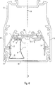
- the luminaire is designed for use in a light strip system, wherein the light band system preferably - as in Fig. 4 sketched in a corresponding cross section - one, along the longitudinal axis extending support rail 10 includes.
- the design is such that the lamp is held in the support rail 10 is arranged or can be arranged, for example via a latching connection.
- the support rail 10 viewed in the cross section may also have a U-shape in a first approximation, so that two U-legs 11, 12 are formed by the mounting rail, wherein the lamp is located within that space or is located between the two U-legs 11, 12 of the support rail 10 extends.
- the lamp has a, arranged in the lamp housing 1 LED light source 2 for generating a light.
- the LED light source 2 comprises an LED board 16, on which a plurality of LEDs 15 are arranged, wherein the LEDs 15 are preferably arranged so that they form one, extending parallel to the longitudinal axis row.
- the luminaire can accordingly be referred to as an LED bar light.
- a light exit opening 13 for the light generated by the LED light source 2 is formed by the free end portions of the two U-legs 11, 12 of the support rail 10. Further preferably, the light exit opening 13 is covered by a translucent cover 14.
- the light band system may be arranged to be oriented for operation such that the light is emitted from the luminaire into the lower half space, as in FIG Fig. 4 indicated by a directional arrow R.
- the mounting rail 10 is fastened to a ceiling, for example, directly or via suspension elements, wherein the two U-legs 11, 12 point vertically downwards.
- a different orientation of the support member 10 relative to the vertical can be provided.
- the design is such that the mounting rail 10 extends further along the longitudinal axis - that is, has a greater length - than the luminaire. Rather, the support rail 10 is preferably so long that a plurality of corresponding lights each frontally adjacent to each other can be arranged in an analogous manner. Thus, with the lighting system and several corresponding luminaires, a particularly long "light band" can be generated.
- the lamp has an optical lens element 3 for influencing the light.
- the design is such that between the LED light source 2 on the one hand and the lens area 6 on the other hand, no further element for optically influencing the light is arranged.
- the lens area 6 can in particular, as in Fig. 1 sketched, on its side facing the LED light source 2 side have a recess formed by a concave shape indentation and have on the opposite side, for example, convex and concave portions.
- the LED light source 2, in particular with its LEDs 15, can advantageously be arranged to intervene in the indentation in terms of lighting technology.
- the optical lens element 3 can be arranged in particular directly on the lamp housing 1, for example, on the connecting leg 19 of the lamp housing 1.
- a particularly simple mounting option is given, if in this case a locking connection is provided.
- the lamp has a reflector 4, which is designed to further influence the light.
- the reflector 4 is arranged held directly on the optical lens element 3.
- the reflector 4 is designed so that it directs the incident on him portion of the light with respect to the direction R at least predominantly on one side, so that an asymmetric light output is achieved. This may be desirable, for example, if a vertical wall is to be illuminated, which is located on the corresponding side obliquely below the lamp.
- the reflector 4 is reversibly detachably arranged in the embodiment shown on the optical lens element 3, in particular it is arranged on the optical lens element 3 held via a snap-in connection. This makes it possible to achieve that the reflector 4 can be dismantled from the lamp in a particularly handling-friendly manner and can be reassembled.
- the optical lens element 3 is preferably formed extending along the longitudinal axis. When viewed in cross-section normal to the longitudinal axis, it preferably has a U-shaped recess 5, wherein the reflector 4 is arranged to engage in the recess 5. As a result, a particularly stable mounting of the reflector 4 on the optical lens element 3 is made possible.
- the recess 5 is elongated, extending with its longitudinal axis substantially perpendicular to the main extension of the two U-legs 17, 18 of the lamp housing 1 or in the orientation considered here horizontal. As a result, a particularly suitable stable suspension of the reflector 4 is possible.
- the recess 5 is - viewed in the normal cross-section - formed on one side adjacent to the lens portion 6, with respect to the Fig. 1 to the left of the lens area 6.
- the desired asymmetrical light deflection through the reflector 4 can be achieved in a particularly suitable manner.
- the reflector 4 for a particularly suitable holder in particular a nub 8 have, which is arranged latchingly engaging in the recess 5.
- Fig. 2 the optical lens element 3 is sketched separated in cross section. It can be seen that a recess 29 that corresponds to the nub 8 can be provided in the recess 5 for a particularly suitable latching connection between the optical lens element 3 and the reflector 4.
- Fig. 3 shows the reflector 4 separated in a corresponding cross-sectional view.
- the optical lens element 3 can be designed profile-like, for example as an extruded component, wherein the corresponding profile axis extends parallel to the longitudinal axis.
- the optical lens element 3 may be made of a plastic such as PC (polycarbonate).
- the optical lens element 3 can advantageously be designed as an ESD protection part (ESD: electrostatic discharge). In this case, it is particularly advantageous if the optical lens element 3 is connected to the luminaire housing 1 in such a way that it can not be dismounted from the latter without a special tool.
- the reflector 4 may also be designed at least substantially profile-like, with the corresponding profile axis extending parallel to the longitudinal axis.
- the reflector 4 may have a plurality of corresponding nubs 8 extending in a row along the longitudinal axis.
- the reflector 4 preferably has a reflection surface 9 which, viewed in the normal cross-section, is concavely curved.
- FIGS. 5a and 5b two schematic sketches of an embodiment are shown, in which the design is such that - viewed in a cross section normal to the longitudinal axis - the light generated by the LED light source 2 is divided by the optical lens element 3 into two separate main components first major portion H1 and a second major portion H2.
- a so-called batwing distribution may be formed here.
- the two main components H1, H2 are formed symmetrically, in particular with respect to the direction R.
- the first major portion H1 is indicated by exemplary light rays
- Fig. 5b the second major share H2 accordingly.
- the first main component H1 falls on the reflection surface 9, while the second main component H2 does not.
- the first main part H1 can be used to illuminate an upper wall area and the second main part H2 to illuminate a lower wall area.
- cover 14 is designed cloudy or milky, because then the risk of unwanted banding can be reduced or even rule out.
- the reflector 4 viewed in the normal cross-section may have an upper horizontal leg 20 which is or can be arranged to engage in the recess 5 of the optical lens element 3 and on which the nubs 8 are formed. Further, the reflector 4 may have a lower horizontal leg 21, which extends - in the orientation considered here - below the upper horizontal leg 20, wherein between the upper horizontal leg 20 and the lower horizontal leg 21, a curved portion 23 is formed through the reflection surface 9 is formed.
- the reflector 4 further comprises an abutment leg 22, which extends from the lower horizontal leg 21 obliquely upward, from the, the curved portion 23 opposite end portion of the lower horizontal leg 21 from.
- the abutment leg 22 is configured to be disposed adjacent to the lower free end portion of the first U-leg 17 of the lamp housing 1.
- the optical lens element 3 can furthermore have an abutment surface 7 for abutting the reflector 4 at an edge region of the recess 5.
- the optical lens element 3 is formed symmetrically with respect to a particular vertical center plane M of the lamp.
- this center plane M extends through the LEDs 15 of the LED light source 2.
- the reflector 4 can optionally be arranged on one of the two sides of the lens region 6 or snapped onto the optical lens element 3.
- the reflector 4 can be generally connected to the optical lens element 3 as intended, regardless of whether the lamp is arranged in the support rail 10 or not.
- the design is further preferably such that the reflector 4 extends only on one side of the median plane M, so does not pass through the median plane M when it is connected as intended with the optical lens element 3.
- the reflector 4 is preferably also disposed within that space which extends between the two U-legs 11, 12 of the support member 10.
- the light exit opening 13 for the light formed by the free end regions of the two U-limbs 11, 12 is, as mentioned above, preferably covered by a light-permeable cover 14.
- the reflector 4 is located behind the cover 14, as seen by a viewer of the light band system. Therefore, the described design is advantageous with respect to the design possibilities of the external appearance of the light band system.
Landscapes
- Engineering & Computer Science (AREA)
- General Engineering & Computer Science (AREA)
- Securing Globes, Refractors, Reflectors Or The Like (AREA)
- Non-Portable Lighting Devices Or Systems Thereof (AREA)
Description
- Die Erfindung betrifft eine Leuchte zur Verwendung in einem Lichtbandsystem, wobei die Leuchte ein Leuchtengehäuse, eine LED-Lichtquelle (LED: Licht emittierende Diode), ein optisches Linsenelement und einen Reflektor aufweist. Weiterhin betrifft die Erfindung ein entsprechendes Lichtbandsystem sowie ein entsprechendes optisches Linsenelement.
- Eine solche Leuchte ist aus der
DE 20 2012 100 628 U1 bekannt. Bei dieser Leuchte ist vorgesehen, dass der Reflektor von außen her an dem Gehäuse der Leuchte aufgeschnappt wird. Daher erstreckt sich der Reflektor in Lichtabstrahlrichtung gesehen deutlich über das Gehäuse hinaus. Hierdurch ist das äußere Erscheinungsbild der Leuchte in der Regel beeinträchtigt. - Der Erfindung liegt die Aufgabe zugrunde, eine entsprechende verbesserte Leuchte anzugeben. Insbesondere soll die Leuchte bei leichter Montagemöglichkeit des Reflektors vorteilhafte Eigenschaften mit Bezug auf die Gestaltungsmöglichkeiten des äußeren Erscheinungsbilds bieten. Außerdem soll ein entsprechendes Lichtbandsystem sowie ein entsprechendes optisches Linsenelement angegeben werden.
- Diese Aufgabe wird gemäß der Erfindung mit den in den unabhängigen Ansprüchen genannten Gegenständne gelöst. Besondere Ausführungsarten der Erfindung sind in den abhängigen Ansprüchen angegeben.
- Gemäß der Erfindung ist eine Leuchte zur Verwendung in einem Lichtbandsystem vorgesehen, die ein, sich längs einer Längsachse erstreckendes längliches Leuchtengehäuse aufweist, sowie eine, in dem Leuchtengehäuse angeordnete LED-Lichtquelle zur Erzeugung eines Lichts. Weiterhin weist die Leuchte ein optisches Linsenelement zur Beeinflussung des Lichts auf, sowie einen Reflektor zur weiteren Beeinflussung des Lichts. Dabei ist der Reflektor unmittelbar an dem optischen Linsenelement gehalten angeordnet.
- Hierdurch lässt sich der Reflektor besonders geeignet unmittelbar mit dem optischen Linsenelement koppeln, wobei insgesamt eine besonders kleinräumige Gestaltung ermöglicht ist. Dies ist insbesondere auch vorteilhaft mit Bezug auf die Gestaltung des äußeren Erscheinungsbilds der Leuchte und auch des Lichtbandsystems.
- Vorzugsweise ist der Reflektor reversibel lösbar an dem optischen Linsenelement gehalten angeordnet. Hierdurch lässt er sich besonders einfach demontieren und wieder montieren. Eine besonders einfache Handhabung ist ermöglicht, wenn der der Reflektor über eine Rastverbindung an dem optischen Linsenelement gehalten angeordnet ist.
- Vorzugsweise ist das optische Linsenelement sich längs der Längsachse erstreckend ausgebildet, wobei es in einem Querschnitt normal zu der Längsachse betrachtet eine U-förmige Ausnehmung aufweist und der Reflektor in die Ausnehmung eingreifend angeordnet ist. Auf diese Weise ist eine besonders zuverlässige Halterung des Reflektors am optischen Linsenelement ermöglicht.
- Vorzugsweise weist das optische Linsenelement einen Linsenbereich zur Beeinflussung des Lichts auf, wobei - in dem Querschnitt betrachtet - die Ausnehmung auf einer Seite neben dem Linsenbereich ausgebildet ist. So eignet sich der Reflektor besonders zur Erzielung einer zu einer Seite hin gerichteten Lichtabgabe der Leuchte, also für eine asymmetrische Lichtabgabe.
- Vorzugsweise weist das optische Linsenelement an einem Randbereich der Ausnehmung eine Anlagefläche zur Anlage des Reflektors auf. Hierdurch lässt sich eine besonders genaue Ausrichtung des Reflektors gegenüber dem optischen Linsenelement bewirken.
- Vorzugsweise weist der Reflektor eine Noppe auf, die rastend in die Ausnehmung eingreifend angeordnet ist. Dies ist vorteilhaft mit Bezug auf eine besonders zuverlässige Halterung und Positionierung des Reflektors.
- Vorzugsweise ist das optische Linsenelement mit Bezug auf eine Mittelebene der Leuchte symmetrisch ausgebildet. Auf diese Weise lässt sich insbesondere erzielen, dass sich der Reflektor einfach - mit Bezug auf die Längsachse - auf zwei gegenüberliegenden Seiten anordnen lässt.
- Vorzugsweise ist der Reflektor sich längs der Längsachse erstreckend ausgebildet, wobei er in einem Querschnitt normal zu der Längsachse betrachtet eine konkave Reflexionsfläche zur Lenkung des Lichts aufweist. Hierdurch ist eine besonders effektive Lichtlenkung ermöglicht.
- Vorzugsweise ist dabei die Gestaltung derart, dass - in dem Querschnitt betrachtet - das Licht durch das optische Linsenelement in zwei voneinander getrennte Hauptanteile aufgeteilt wird, wobei einer der beiden Hauptanteile auf die Reflexionsfläche des Reflektors fällt und der andere Hauptanteil nicht auf die Reflexionsfläche fällt. Hierdurch lässt sich beispielsweise erzielen, dass der nicht an der Reflexionsfläche reflektierte Hauptanteil zur Beleuchtung eines unteren Bereichs einer Wand dient und der an der Reflexionsfläche reflektierte Hauptanteil zur Beleuchtung eines oberen Bereichs der Wand.
- Gemäß einem weiteren Aspekt der Erfindung ist ein Lichtbandsystem vorgesehen, das eine sich längs einer Längsachse erstreckende Tagschiene aufweist sowie eine erfindungsgemäße Leuchte, die in der Tragschiene gehalten angeordnet ist.
- Vorzugsweise weist dabei die Tragschiene in einem Querschnitt normal zu der Längsachse betrachtet in erster Näherung eine U-Form auf, so dass zwei U-Schenkel gebildet sind, wobei die Leuchte innerhalb des Raums angeordnet ist, der sich zwischen den beiden U-Schenkeln erstreckt. Hierdurch ist eine besonders unauffällige Gestaltung ermöglicht.
- Vorzugsweise ist dabei der Reflektor ebenfalls innerhalb des Raums angeordnet, der sich zwischen den beiden U-Schenkeln erstreckt. Hierdurch lässt sich insbesondere erzielen, dass das Erscheinungsbild auch nicht durch einen über die Tragschiene vorstehenden Reflektor beeinträchtigt wird.
- Vorzugsweise ist dabei durch die freien Endbereiche der beiden U-Schenkel eine Lichtaustrittsöffnung für das Licht gebildet, wobei die Lichtaustrittsöffnung durch eine lichtdurchlässige Abdeckung abgedeckt ist. So lässt sich insbesondere auch der Reflektor besonders unauffällig hinter der Abdeckung anordnen. Wenn die Abdeckung trüb bzw. milchig ist, lässt sich insbesondere die Gefahr einer ungewollten Streifenbildung verringern.
- Gemäß einem weiteren Aspekt der Erfindung ist ein längliches, sich längs einer Längsachse erstreckendes optisches Linsenelement für eine Leuchte vorgesehen, die zur Verwendung in einem Lichtbandsystem ausgestaltet ist und ein, sich längs der Längsachse erstreckendes längliches Leuchtengehäuse aufweist sowie eine, in dem Leuchtengehäuse angeordnete LED-Lichtquelle zur Erzeugung eines Lichts, insbesondere für eine erfindungsgemäße Leuchte. Das optische Linsenelement weist dabei einen Linsenbereich zur Beeinflussung des Lichts auf. In einem Querschnitt normal zu der Längsachse betrachtet weist das optische Linsenelement eine U-förmige Ausnehmung auf, die zur Halterung eines Reflektors ausgestaltet ist.
- Die Erfindung wird im Folgenden anhand eines Ausführungsbeispiels und mit Bezug auf die Zeichnungen näher erläutert. Es zeigen:
- Fig. 1
- eine Querschnitt-Skizze einer erfindungsgemäßen Leuchte,
- Fig. 2
- eine Querschnitt-Skizze des optischen Linsenelements der Leuchte,
- Fig. 3
- eine Querschnitt-Skizze des Reflektors der Leuchte,
- Fig. 4
- eine Querschnitt-Skizze eines Lichtbandsystems mit einer erfindungsgemäßen Leuchte und
- Figuren 5a und 5b
- zwei Querschnitt-Skizzen zur Illustration der Aufteilung des Lichts durch das optische Linsenelement in zwei Hauptanteile.
-
Fig. 1 zeigt einen Querschnitt durch eine erfindungsgemäße Leuchte. Die Leuchte weist ein, sich längs einer Längsachse erstreckendes längliche Leuchtengehäuse 1 auf. Vorzugsweise ist das Leuchtengehäuse 1 wie im gezeigten Beispiel der Fall als ein Profilelement gestaltet, wobei die Profilachse parallel zur Längsachse gerichtet ist.Fig. 1 zeigt einen Querschnitt normal zur Längsachse bzw. normal zur Profilachse. - Vorzugsweise ist das Leuchtengehäuse 1 im normalen Querschnitt betrachtet in erster Näherung U-förmig, so dass ein erster U-Schenkel 17, ein zweiter U-Schenkel 18 und ein, die beiden U-Schenkel 17, 18 miteinander verbindender Verbindungsschenkel 19 gebildet sind.
- Die Leuchte ist zur Verwendung in einem Lichtbandsystem ausgestaltet, wobei das Lichtbandsystem vorzugsweise - wie in
Fig. 4 in einem entsprechenden Querschnitt skizziert - eine, sich längs der Längsachse erstreckende Tragschiene 10 umfasst. Die Gestaltung ist dabei derart, dass die Leuchte in der Tragschiene 10 gehalten angeordnet ist bzw. angeordnet werden kann, beispielsweise über eine Rastverbindung. Insbesondere kann die Tragschiene 10 in dem Querschnitt betrachtet ebenfalls in erster Näherung eine U-Form aufweisen, so dass auch durch die Tragschiene zwei U-Schenkel 11, 12 gebildet sind, wobei die Leuchte innerhalb desjenigen Raums angeordnet ist bzw. wird, der sich zwischen den beiden U-Schenkeln 11, 12 der Tragschiene 10 erstreckt. - Weiterhin weist die Leuchte eine, in dem Leuchtengehäuse 1 angeordnete LED-Lichtquelle 2 zur Erzeugung eines Lichts auf. Im gezeigten Beispiel umfasst die LED-Lichtquelle 2 eine LED-Platine 16, auf der mehrere LEDs 15 angeordnet sind, wobei die LEDs 15 vorzugsweise so angeordnet sind, dass sie eine, sich parallel zur Längsachse erstreckende Reihe bilden. Die Leuchte kann dementsprechend als LED-Balkenleuchte bezeichnet werden.
- Vorzugsweise ist durch die freien Endbereiche der beiden U-Schenkel 11, 12 der Tragschiene 10 eine Lichtaustrittsöffnung 13 für das von der LED-Lichtquelle 2 erzeugte Licht gebildet. Weiterhin vorzugsweise ist dabei die Lichtaustrittsöffnung 13 durch eine lichtdurchlässige Abdeckung 14 abgedeckt.
- Das Lichtbandsystem kann dazu vorgesehen sein, zum Betrieb derart orientiert zu werden, dass das Licht von der Leuchte in den unteren Halbraum abgegeben wird, wie in
Fig. 4 durch einen Richtungspfeil R angedeutet. Beispielsweise kann also vorgesehen sein, dass die Tragschiene 10 an einer Raumdecke befestigt wird, beispielsweise direkt oder über Aufhängelemente, wobei die beiden U-Schenkel 11, 12 vertikal nach unten weisen. In dieser Beschreibung wird von einer solchen Orientierung ausgegangen. Im Allgemeinen kann jedoch auch eine andere Orientierung des Trägerelements 10 gegenüber der Vertikalen vorgesehen sein. - Bei dem hier betrachteten Lichtbandsystem ist die Gestaltung derart, dass sich die Tragschiene 10 entlang der Längsachse weiter erstreckt - also eine größere Länge aufweist - als die Leuchte. Die Tragschiene 10 ist vielmehr vorzugsweise so lange, dass mehrere entsprechende Leuchten jeweils stirnseitig aneinandergrenzend in ihr in analoger Weise angeordnet werden können. So lässt sich mit dem Lichtbandsystem und mehreren entsprechenden Leuchten ein besonders langes "Lichtband" erzeugen.
- Weiterhin weist die Leuchte ein optisches Linsenelement 3 zur Beeinflussung des Lichts auf. Insbesondere weist das optische Linsenelement 3 hierzu einen Linsenbereich 6 auf, wobei das optische Linsenelement 3 derart angeordnet ist, dass der größte Teil des von der LED-Lichtquelle 2 erzeugten Lichts den Linsenbereich 6 durchsetzt. Vorzugsweise ist die Gestaltung dabei derart, dass zwischen der LED-Lichtquelle 2 einerseits und dem Linsenbereich 6 andererseits kein weiteres Element zur optischen Beeinflussung des Lichts angeordnet ist.
- Der Linsenbereich 6 kann insbesondere, wie in
Fig. 1 skizziert, auf seiner zur LED-Lichtquelle 2 weisenden Seite eine durch eine konkave Form gebildete Einbuchtung aufweisen und auf der gegenüberliegenden Seite beispielsweise konvexe und konkave Abschnitte aufweisen. Dabei kann die LED-Lichtquelle 2, insbesondere mit ihren LEDs 15 lichttechnisch vorteilhaft in die Einbuchtung eingreifend angeordnet sein. - Vorzugsweise kann das optische Linsenelement 3 insbesondere unmittelbar an dem Leuchtengehäuse 1 angeordnet sein, beispielsweise an dem Verbindungsschenkel 19 des Leuchtengehäuses 1. Eine besonders einfache Montagemöglichkeit ist gegeben, wenn hierbei eine Rastverbindung vorgesehen ist.
- Weiterhin weist die Leuchte einen Reflektor 4 auf, der zur weiteren Beeinflussung des Lichts ausgestaltet ist. Dabei ist der Reflektor 4 unmittelbar an dem optischen Linsenelement 3 gehalten angeordnet. Im gezeigten Ausführungsbeispiel ist der Reflektor 4 so gestaltet, dass er den auf ihn auftreffenden Anteil des Lichts mit Bezug auf die Richtung R zumindest überwiegend auf eine Seite lenkt, so dass eine asymmetrische Lichtabgabe erzielt wird. Dies kann beispielsweise erwünscht sein, wenn eine vertikale Wand beleuchtet werden soll, die sich auf der entsprechenden Seite schräg unterhalb der Leuchte befindet.
- Der Reflektor 4 ist beim gezeigten Ausführungsbeispiel reversibel lösbar an dem optischen Linsenelement 3 angeordnet, insbesondere ist er an dem optischen Linsenelement 3 über eine Rastverbindung gehalten angeordnet. Hierdurch lässt sich erzielen, dass der Reflektor 4 besonders handhabungsfreundlich von der Leuchte demontiert werden kann und wieder montiert werden kann.
- Das optische Linsenelement 3 ist vorzugsweise sich längs der Längsachse erstreckend ausgebildet. Im Querschnitt normal zu der Längsachse betrachtet weist es dabei vorzugsweise eine U-förmige Ausnehmung 5 auf, wobei der Reflektor 4 in die Ausnehmung 5 eingreifend angeordnet ist. Hierdurch ist eine besonders stabile Halterung des Reflektors 4 an dem optischen Linsenelement 3 ermöglicht. Im gezeigten Beispiel ist die Ausnehmung 5 länglich gestaltet, wobei sie sich mit ihrer Längsachse im Wesentlichen senkrecht zur Haupterstreckung der beiden U-Schenkel 17, 18 des Leuchtengehäuses 1 erstreckt bzw. bei der hier betrachteten Orientierung waagrecht. Hierdurch ist eine besonders geeignete stabile Aufhängung des Reflektors 4 ermöglicht.
- Die Ausnehmung 5 ist dabei - in dem normalen Querschnitt betrachtet - auf einer Seite neben dem Linsenbereich 6 ausgebildet, mit Bezug auf die
Fig. 1 links von dem Linsenbereich 6. So lässt sich besonders geeignet die gewünschte asymmetrische Lichtlenkung durch den Reflektor 4 erzielen. - Wie beispielhaft gezeigt, kann der Reflektor 4 für eine besonders geeignete Halterung insbesondere eine Noppe 8 aufweisen, die rastend in die Ausnehmung 5 eingreifend angeordnet ist.
- In
Fig. 2 ist das optische Linsenelement 3 im Querschnitt separiert skizziert. Man erkennt, dass in der Ausnehmung 5 eine, zu der Noppe 8 korrespondierend geformte Vertiefung 29 für eine besonders geeignete rastende Verbindung zwischen dem optischen Linsenelement 3 und dem Reflektor 4 vorgesehen sein kann.Fig. 3 zeigt den Reflektor 4 in entsprechender Querschnittdarstellung separiert. - Vorteilhaft kann das optische Linsenelement 3 profilartig gestaltet sein, beispielsweise als extrudiertes Bauteil, wobei sich die entsprechende Profilachse parallel zur Längsachse erstreckt. Vorteilhaft kann das optische Linsenelement 3 aus einem Kunststoff wie beispielsweise PC (Polycarbonat) gefertigt sein. Das optische Linsenelement 3 kann vorteilhaft als ESD-Schutzteil (ESD: electrostatic discharge) gestaltet sein. Hierbei ist es insbesondere vorteilhaft, wenn das optische Linsenelement 3 so mit dem Leuchtengehäuse 1 verbunden ist, dass es sich ohne ein spezielles Werkzeug nicht von Letzterem demontieren lässt.
- Der Reflektor 4 kann zumindest im Wesentlichen ebenfalls profilartig gestaltet sein, wobei sich die entsprechende Profilachse parallel zur Längsachse erstreckt. Dabei kann der Reflektor 4 mehrere, sich entlang der Längsachse in einer Reihe erstreckende entsprechende Noppen 8 aufweisen. Hierdurch ist eine besonders stabile Verbindung zwischen dem optischen Linsenelement 3 und dem Reflektor 4 ermöglicht.
- Für eine besonders geeignete Lichtlenkung weist der Reflektor 4 vorzugsweise eine Reflexionsfläche 9 auf, die im normalen Querschnitt betrachtet konkav gewölbt ist.
- In den
Figuren 5a und 5b sind zwei schematische Skizzen zu einer Ausführung gezeigt, bei der die Gestaltung derart ist, dass - in einem Querschnitt normal zu der Längsachse betrachtet - das von der LED-Lichtquelle 2 erzeugte Licht durch das optische Linsenelement 3 in zwei voneinander getrennte Hauptanteile aufgeteilt wird, einen ersten Hauptanteil H1 und einen zweiten Hauptanteil H2. Beispielsweise kann hierbei eine so genannte Batwing-Verteilung gebildet sein. Dabei sind die beiden Hauptanteile H1, H2 insbesondere mit Bezug auf die Richtung R symmetrisch ausgebildet. InFig. 5a ist lediglich der erste Hauptanteil H1 durch exemplarische Lichtstrahlen angedeutet, inFig. 5b der zweite Hauptanteil H2 entsprechend. Der erste Hauptanteil H1 fällt dabei auf die Reflexionsfläche 9, der zweite Hauptanteil H2 dagegen nicht. So lässt sich vorteilhaft beispielsweise eine senkrechte Wand beleuchten, die sich seitlich rechts unterhalb der Leuchte 1 befindet. Der erste Hauptanteil H1 kann dabei zur Beleuchtung eines oberen Wandbereichs genutzt werden und der zweite Hauptanteil H2 zur Beleuchtung eines unteren Wandbereichs. - Hierbei ist es besonders vorteilhaft, wenn die Abdeckung 14 trüb bzw. milchig gestaltet ist, denn so lässt sich die Gefahr einer ungewollten Streifenbildung verringern oder gar ausschließen.
- Wie im gezeigten Beispiel der Fall kann der Reflektor 4 im normalen Querschnitt betrachtet einen oberen waagrechten Schenkel 20 aufweisen, der in die Ausnehmung 5 des optischen Linsenelements 3 eingreifend angeordnet ist bzw. werden kann und an dem die Noppen 8 angeformt sind. Weiter kann der Reflektor 4 einen unteren waagrechten Schenkel 21 aufweisen, der sich - bei der hier betrachteten Orientierung - unterhalb des oberen waagrechten Schenkels 20 erstreckt, wobei zwischen dem oberen waagrechten Schenkel 20 und dem unteren waagrechten Schenkel 21 ein gekrümmter Abschnitt 23 ausgebildet ist, durch den die Reflexionsfläche 9 gebildet ist. Vorteilhaft weist der Reflektor 4 weiterhin einen Anlageschenkel 22 auf, der sich von dem unteren waagrechten Schenkel 21 aus nach schräg oben erstreckt, und zwar von dem, dem gekrümmten Abschnitt 23 gegenüberliegenden Endbereich des unteren waagrechten Schenkels 21 aus. Der Anlageschenkel 22 ist dazu ausgestaltet, an den unteren freien Endbereich des ersten U-Schenkels 17 des Leuchtengehäuses 1 anliegend angeordnet zu werden. Hierdurch ist eine besonders präzise Ausrichtung bzw. Positionierung des Reflektors 4 gegenüber dem Leuchtengehäuse 1 ermöglicht.
- Ebenfalls für eine besonders präzise Ausrichtung des Reflektors 4 kann das optische Linsenelement 3 weiterhin an einem Randbereich der Ausnehmung 5 eine Anlagefläche 7 zur Anlage des Reflektors 4 aufweisen.
- Weiterhin vorzugsweise ist das optische Linsenelement 3 mit Bezug auf eine insbesondere vertikale Mittelebene M der Leuchte symmetrisch ausgebildet. Beim gezeigten Beispiel verläuft diese Mittelebene M durch die LEDs 15 der LED-Lichtquelle 2. Auf diese Weise lässt sich erzielen, dass der Reflektor 4 wahlweise auf einer der beiden Seiten des Linsenbereichs 6 angeordnet bzw. an dem optischen Linsenelement 3 eingerastet werden kann.
- Der Reflektor 4 lässt sich im Allgemeinen mit dem optischen Linsenelement 3 wie vorgesehen verbinden, unabhängig davon, ob die Leuchte in der Tragschiene 10 angeordnet ist oder nicht.
- Wie insbesondere der
Fig. 4 zu entnehmen, ist die Gestaltung weiterhin vorzugsweise derart, dass sich der Reflektor 4 lediglich auf einer Seite der Mittelebene M erstreckt, also nicht die Mittelebene M durchgreift, wenn er wie vorgesehen mit dem optischen Linsenelement 3 verbunden ist. - Wie weiterhin in
Fig. 4 beispielhaft skizziert, ist der Reflektor 4 vorzugsweise ebenfalls innerhalb desjenigen Raums angeordnet, der sich zwischen den beiden U-Schenkeln 11, 12 des Trägerelements 10 erstreckt. Die durch die freien Endbereiche der beiden U-Schenkel 11, 12 gebildete Lichtaustrittsöffnung 13 für das Licht ist, wie oben erwähnt, vorzugsweise durch eine lichtdurchlässige Abdeckung 14 abgedeckt. Durch die beschriebene Gestaltung befindet sich der Reflektor 4, von einem Betrachter des Lichtbandsystems aus gesehen, hinter der Abdeckung 14. Daher ist die beschriebene Gestaltung vorteilhaft mit Bezug auf die Gestaltungsmöglichkeiten des äußeren Erscheinungsbilds des Lichtbandsystems.
Claims (15)
- Leuchte zur Verwendung in einem Lichtbandsystem, aufweisend- ein, sich längs einer Längsachse erstreckendes längliches Leuchtengehäuse (1),- eine, in dem Leuchtengehäuse (1) angeordnete LED-Lichtquelle (2) zur Erzeugung eines Lichts,- ein optisches Linsenelement (3) zur Beeinflussung des Lichts,- einen Reflektor (4) zur weiteren Beeinflussung des Lichts,dadurch gekennzeichnet,
dass der Reflektor (4) unmittelbar an dem optischen Linsenelement (3) gehalten angeordnet ist. - Leuchte nach Anspruch 1,
dadurch gekennzeichnet,
dass der Reflektor (4) reversibel lösbar an dem optischen Linsenelement (3) gehalten angeordnet ist. - Leuchte nach Anspruch 1 oder 2,
dadurch gekennzeichnet,
dass der Reflektor (4) über eine Rastverbindung an dem optischen Linsenelement (3) gehalten angeordnet ist. - Leuchte nach einem der vorhergehenden Ansprüche,
dadurch gekennzeichnet,
dass das optische Linsenelement (3) sich längs der Längsachse erstreckend ausgebildet ist und in einem Querschnitt normal zu der Längsachse betrachtet eine U-förmige Ausnehmung (5) aufweist, wobei der Reflektor (4) in die Ausnehmung (5) eingreifend angeordnet ist. - Leuchte nach Anspruch 4,
dadurch gekennzeichnet,
dass das optische Linsenelement (3) einen Linsenbereich (6) zur Beeinflussung des Lichts aufweist, wobei - in dem Querschnitt betrachtet - die Ausnehmung (5) auf einer Seite neben dem Linsenbereich (6) ausgebildet ist. - Leuchte nach Anspruch 4 oder 5,
dadurch gekennzeichnet,
dass das optische Linsenelement (3) an einem Randbereich der Ausnehmung (5) eine Anlagefläche (7) zur Anlage des Reflektors (4) aufweist. - Leuchte nach einem der Ansprüche 4 bis 6,
dadurch gekennzeichnet,
dass der Reflektor (4) eine Noppe (8) aufweist, die rastend in die Ausnehmung (5) eingreifend angeordnet ist. - Leuchte nach einem der vorhergehenden Ansprüche,
dadurch gekennzeichnet,
dass das optische Linsenelement (3) mit Bezug auf eine Mittelebene (M) der Leuchte symmetrisch ausgebildet ist. - Leuchte nach einem der vorhergehenden Ansprüche,
dadurch gekennzeichnet,
dass der Reflektor (4) sich längs der Längsachse erstreckend ausgebildet ist und in einem Querschnitt normal zu der Längsachse betrachtet eine konkave Reflexionsfläche (9) zur Lenkung des Lichts aufweist. - Leuchte nach Anspruch 9,
dadurch gekennzeichnet,
dass die Gestaltung derart ist, dass - in dem Querschnitt betrachtet - das Licht durch das optische Linsenelement (3) in zwei voneinander getrennte Hauptanteile aufgeteilt wird, wobei einer der beiden Hauptanteile auf die Reflexionsfläche (9) des Reflektors (4) fällt und der andere Hauptanteil nicht auf die Reflexionsfläche (9) fällt. - Lichtbandsystem, aufweisend- eine, sich längs einer Längsachse (L) erstreckende Tagschiene (10),- eine Leuchte nach einem der vorhergehenden Ansprüche,wobei die Leuchte in der Tragschiene (10) gehalten angeordnet ist.
- Lichtbandsystem nach Anspruch 11,
dadurch gekennzeichnet,
dass die Tragschiene (10) in einem Querschnitt normal zu der Längsachse betrachtet in erster Näherung eine U-Form aufweist, so dass zwei U-Schenkel (11, 12) gebildet sind, wobei die Leuchte innerhalb des Raums angeordnet ist, der sich zwischen den beiden U-Schenkeln (11, 12) erstreckt. - Lichtbandsystem nach Anspruch 12,
dadurch gekennzeichnet,
dass der Reflektor (4) ebenfalls innerhalb des Raums angeordnet ist, der sich zwischen den beiden U-Schenkeln (11, 12) erstreckt. - Lichtbandsystem nach Anspruch 12 oder 13,
dadurch gekennzeichnet,
dass durch die freien Endbereiche der beiden U-Schenkel (11, 12) eine Lichtaustrittsöffnung (13) für das Licht gebildet ist, wobei die Lichtaustrittsöffnung (13) durch eine lichtdurchlässige Abdeckung (14) abgedeckt ist, vorzugsweise eine trüb bzw. milchig gestaltete Abdeckung (14). - Längliches, sich längs einer Längsachse erstreckendes optisches Linsenelement (3) für eine Leuchte, die zur Verwendung in einem Lichtbandsystem ausgestaltet ist und ein, sich längs der Längsachse (L) erstreckendes längliches Leuchtengehäuse (1) aufweist sowie eine, in dem Leuchtengehäuse (1) angeordnete LED-Lichtquelle (2) zur Erzeugung eines Lichts,
wobei das optische Linsenelement (3) einen Linsenbereich (6) zur Beeinflussung des Lichts aufweist,
dadurch gekennzeichnet,
dass das optische Linsenelement (3) in einem Querschnitt normal zu der Längsachse betrachtet eine U-förmige Ausnehmung (5) aufweist, die zur Halterung eines Reflektors (4) ausgestaltet ist.
Applications Claiming Priority (1)
| Application Number | Priority Date | Filing Date | Title |
|---|---|---|---|
| DE202015105154.9U DE202015105154U1 (de) | 2015-09-30 | 2015-09-30 | Lichtbandsystem-Leuchte mit Reflektor, Lichtbandsystem und optisches Linsenelement |
Publications (2)
| Publication Number | Publication Date |
|---|---|
| EP3150908A1 true EP3150908A1 (de) | 2017-04-05 |
| EP3150908B1 EP3150908B1 (de) | 2018-04-25 |
Family
ID=57123810
Family Applications (1)
| Application Number | Title | Priority Date | Filing Date |
|---|---|---|---|
| EP16191403.1A Active EP3150908B1 (de) | 2015-09-30 | 2016-09-29 | Lichtbandsystem-leuchte mit reflektor, lichtbandsystem und optisches linsenelement |
Country Status (3)
| Country | Link |
|---|---|
| EP (1) | EP3150908B1 (de) |
| AT (1) | AT16316U1 (de) |
| DE (1) | DE202015105154U1 (de) |
Cited By (1)
| Publication number | Priority date | Publication date | Assignee | Title |
|---|---|---|---|---|
| WO2024051964A1 (en) * | 2022-09-07 | 2024-03-14 | Eaton Intelligent Power Limited | Lever actuated locking mechanism |
Families Citing this family (5)
| Publication number | Priority date | Publication date | Assignee | Title |
|---|---|---|---|---|
| DE102016104223A1 (de) * | 2016-01-26 | 2017-07-27 | Siteco Beleuchtungstechnik Gmbh | Leuchte mit Indirektbeleuchtung |
| DE102021003238A1 (de) * | 2021-06-24 | 2022-12-29 | pronorm Einbauküchen GmbH | Vorrichtung für eine Betätigung beweglicher Möbelteile |
| IT202100023114A1 (it) * | 2021-09-07 | 2023-03-07 | Sideis S R L | Dispositivo e sistema di illuminazione per gallerie stradali |
| DE102021132818A1 (de) | 2021-12-13 | 2023-06-15 | Odelo Gmbh | Fahrzeugleuchte mit ESD Schutz |
| DE102023108552A1 (de) * | 2023-04-04 | 2024-10-10 | Trilux Gmbh & Co. Kg | Leuchtmittel, Leuchte sowie Leuchtmittelsystem |
Citations (3)
| Publication number | Priority date | Publication date | Assignee | Title |
|---|---|---|---|---|
| US20120120645A1 (en) * | 2010-05-12 | 2012-05-17 | Kenall Manufacturing | Sealed Unibody-Reflector Luminaire |
| DE102011079404A1 (de) * | 2011-07-19 | 2013-01-24 | Zumtobel Lighting Gmbh | Anordnung zur Lichtabgabe |
| DE202012100628U1 (de) | 2012-02-24 | 2013-05-27 | Zumtobel Lighting Gmbh | Leuchte mit einem länglichen Gehäuse und Anbauelement hierfür |
Family Cites Families (3)
| Publication number | Priority date | Publication date | Assignee | Title |
|---|---|---|---|---|
| CN203615246U (zh) * | 2013-12-11 | 2014-05-28 | 惠州雷士光电科技有限公司 | 一种led照明模组 |
| DE102014004472B4 (de) * | 2014-03-28 | 2015-11-05 | Nordeon Gmbh | Leuchtmodul aufweisend ein optisches Element |
| DE202014105391U1 (de) * | 2014-11-11 | 2016-02-12 | Zumtobel Lighting Gmbh | Lichtleitelement zur Beeinflussung eines von LEDs abgestrahlten Lichts sowie Anordnung zur Lichtabgabe mit einem solchen Lichtleitelement und Leuchte |
-
2015
- 2015-09-30 DE DE202015105154.9U patent/DE202015105154U1/de not_active Expired - Lifetime
- 2015-12-21 AT ATGM373/2015U patent/AT16316U1/de not_active IP Right Cessation
-
2016
- 2016-09-29 EP EP16191403.1A patent/EP3150908B1/de active Active
Patent Citations (3)
| Publication number | Priority date | Publication date | Assignee | Title |
|---|---|---|---|---|
| US20120120645A1 (en) * | 2010-05-12 | 2012-05-17 | Kenall Manufacturing | Sealed Unibody-Reflector Luminaire |
| DE102011079404A1 (de) * | 2011-07-19 | 2013-01-24 | Zumtobel Lighting Gmbh | Anordnung zur Lichtabgabe |
| DE202012100628U1 (de) | 2012-02-24 | 2013-05-27 | Zumtobel Lighting Gmbh | Leuchte mit einem länglichen Gehäuse und Anbauelement hierfür |
Cited By (1)
| Publication number | Priority date | Publication date | Assignee | Title |
|---|---|---|---|---|
| WO2024051964A1 (en) * | 2022-09-07 | 2024-03-14 | Eaton Intelligent Power Limited | Lever actuated locking mechanism |
Also Published As
| Publication number | Publication date |
|---|---|
| DE202015105154U1 (de) | 2017-01-02 |
| EP3150908B1 (de) | 2018-04-25 |
| AT16316U1 (de) | 2019-07-15 |
Similar Documents
| Publication | Publication Date | Title |
|---|---|---|
| EP3150908B1 (de) | Lichtbandsystem-leuchte mit reflektor, lichtbandsystem und optisches linsenelement | |
| DE102013226181B4 (de) | Optisches Element, sowie Anordnung zur Lichtabgabe | |
| EP3105499B2 (de) | Längliche mehrteilige linsenanordnung sowie leuchte mit einer solchen linsenanordnung | |
| DE102014004472B4 (de) | Leuchtmodul aufweisend ein optisches Element | |
| EP3607247B1 (de) | Leuchte | |
| EP3748223B1 (de) | Anordnung zur lichtabgabe | |
| EP2913582B1 (de) | Diffusor für eine Leuchte | |
| EP4509755A1 (de) | Beleuchtungsvorrichtung | |
| EP3212997B1 (de) | Optisches element sowie anordnung zur lichtabgabe mit einem optischen element | |
| EP3283820A1 (de) | Optisches system sowie anordnung zur lichtabgabe | |
| EP2626621B1 (de) | Leuchte | |
| EP3832194A1 (de) | Optisches system zum beeinflussen der lichtabgabe einer länglichen lichtquelle | |
| DE202012100628U1 (de) | Leuchte mit einem länglichen Gehäuse und Anbauelement hierfür | |
| EP2647903B1 (de) | Linsenelement insbesondere für Notlichtmodul | |
| DE202014105391U1 (de) | Lichtleitelement zur Beeinflussung eines von LEDs abgestrahlten Lichts sowie Anordnung zur Lichtabgabe mit einem solchen Lichtleitelement und Leuchte | |
| DE102014111660A1 (de) | Frontleuchte | |
| EP2940374A1 (de) | Optisches element für eine lichtquelle einer leuchte, sowie leuchte | |
| DE202018101450U1 (de) | Linse für eine Leuchte und Leuchte mit einer solchen Linse | |
| AT500432A1 (de) | Beleuchtungsvorrichtung |
Legal Events
| Date | Code | Title | Description |
|---|---|---|---|
| PUAI | Public reference made under article 153(3) epc to a published international application that has entered the european phase |
Free format text: ORIGINAL CODE: 0009012 |
|
| STAA | Information on the status of an ep patent application or granted ep patent |
Free format text: STATUS: THE APPLICATION HAS BEEN PUBLISHED |
|
| AK | Designated contracting states |
Kind code of ref document: A1 Designated state(s): AL AT BE BG CH CY CZ DE DK EE ES FI FR GB GR HR HU IE IS IT LI LT LU LV MC MK MT NL NO PL PT RO RS SE SI SK SM TR |
|
| AX | Request for extension of the european patent |
Extension state: BA ME |
|
| STAA | Information on the status of an ep patent application or granted ep patent |
Free format text: STATUS: REQUEST FOR EXAMINATION WAS MADE |
|
| 17P | Request for examination filed |
Effective date: 20170913 |
|
| RBV | Designated contracting states (corrected) |
Designated state(s): AL AT BE BG CH CY CZ DE DK EE ES FI FR GB GR HR HU IE IS IT LI LT LU LV MC MK MT NL NO PL PT RO RS SE SI SK SM TR |
|
| RIC1 | Information provided on ipc code assigned before grant |
Ipc: F21V 5/00 20150101AFI20171011BHEP Ipc: F21V 17/06 20060101ALI20171011BHEP Ipc: F21Y 115/10 20160101ALN20171011BHEP Ipc: F21V 7/00 20060101ALI20171011BHEP Ipc: F21V 21/02 20060101ALI20171011BHEP Ipc: F21Y 103/10 20160101ALN20171011BHEP Ipc: F21V 17/16 20060101ALI20171011BHEP Ipc: F21V 13/04 20060101ALI20171011BHEP Ipc: F21V 17/00 20060101ALI20171011BHEP |
|
| GRAP | Despatch of communication of intention to grant a patent |
Free format text: ORIGINAL CODE: EPIDOSNIGR1 |
|
| STAA | Information on the status of an ep patent application or granted ep patent |
Free format text: STATUS: GRANT OF PATENT IS INTENDED |
|
| INTG | Intention to grant announced |
Effective date: 20171201 |
|
| GRAS | Grant fee paid |
Free format text: ORIGINAL CODE: EPIDOSNIGR3 |
|
| GRAA | (expected) grant |
Free format text: ORIGINAL CODE: 0009210 |
|
| STAA | Information on the status of an ep patent application or granted ep patent |
Free format text: STATUS: THE PATENT HAS BEEN GRANTED |
|
| AK | Designated contracting states |
Kind code of ref document: B1 Designated state(s): AL AT BE BG CH CY CZ DE DK EE ES FI FR GB GR HR HU IE IS IT LI LT LU LV MC MK MT NL NO PL PT RO RS SE SI SK SM TR |
|
| REG | Reference to a national code |
Ref country code: GB Ref legal event code: FG4D Free format text: NOT ENGLISH |
|
| REG | Reference to a national code |
Ref country code: CH Ref legal event code: EP Ref country code: CH Ref legal event code: NV Representative=s name: FELBER UND PARTNER AG, CH |
|
| REG | Reference to a national code |
Ref country code: AT Ref legal event code: REF Ref document number: 993309 Country of ref document: AT Kind code of ref document: T Effective date: 20180515 |
|
| REG | Reference to a national code |
Ref country code: IE Ref legal event code: FG4D Free format text: LANGUAGE OF EP DOCUMENT: GERMAN |
|
| REG | Reference to a national code |
Ref country code: DE Ref legal event code: R096 Ref document number: 502016000938 Country of ref document: DE |
|
| REG | Reference to a national code |
Ref country code: NL Ref legal event code: MP Effective date: 20180425 |
|
| REG | Reference to a national code |
Ref country code: LT Ref legal event code: MG4D |
|
| PG25 | Lapsed in a contracting state [announced via postgrant information from national office to epo] |
Ref country code: NL Free format text: LAPSE BECAUSE OF FAILURE TO SUBMIT A TRANSLATION OF THE DESCRIPTION OR TO PAY THE FEE WITHIN THE PRESCRIBED TIME-LIMIT Effective date: 20180425 |
|
| REG | Reference to a national code |
Ref country code: FR Ref legal event code: PLFP Year of fee payment: 3 |
|
| PG25 | Lapsed in a contracting state [announced via postgrant information from national office to epo] |
Ref country code: ES Free format text: LAPSE BECAUSE OF FAILURE TO SUBMIT A TRANSLATION OF THE DESCRIPTION OR TO PAY THE FEE WITHIN THE PRESCRIBED TIME-LIMIT Effective date: 20180425 Ref country code: SE Free format text: LAPSE BECAUSE OF FAILURE TO SUBMIT A TRANSLATION OF THE DESCRIPTION OR TO PAY THE FEE WITHIN THE PRESCRIBED TIME-LIMIT Effective date: 20180425 Ref country code: BG Free format text: LAPSE BECAUSE OF FAILURE TO SUBMIT A TRANSLATION OF THE DESCRIPTION OR TO PAY THE FEE WITHIN THE PRESCRIBED TIME-LIMIT Effective date: 20180725 Ref country code: FI Free format text: LAPSE BECAUSE OF FAILURE TO SUBMIT A TRANSLATION OF THE DESCRIPTION OR TO PAY THE FEE WITHIN THE PRESCRIBED TIME-LIMIT Effective date: 20180425 Ref country code: NO Free format text: LAPSE BECAUSE OF FAILURE TO SUBMIT A TRANSLATION OF THE DESCRIPTION OR TO PAY THE FEE WITHIN THE PRESCRIBED TIME-LIMIT Effective date: 20180725 Ref country code: PL Free format text: LAPSE BECAUSE OF FAILURE TO SUBMIT A TRANSLATION OF THE DESCRIPTION OR TO PAY THE FEE WITHIN THE PRESCRIBED TIME-LIMIT Effective date: 20180425 Ref country code: LT Free format text: LAPSE BECAUSE OF FAILURE TO SUBMIT A TRANSLATION OF THE DESCRIPTION OR TO PAY THE FEE WITHIN THE PRESCRIBED TIME-LIMIT Effective date: 20180425 |
|
| PG25 | Lapsed in a contracting state [announced via postgrant information from national office to epo] |
Ref country code: LV Free format text: LAPSE BECAUSE OF FAILURE TO SUBMIT A TRANSLATION OF THE DESCRIPTION OR TO PAY THE FEE WITHIN THE PRESCRIBED TIME-LIMIT Effective date: 20180425 Ref country code: RS Free format text: LAPSE BECAUSE OF FAILURE TO SUBMIT A TRANSLATION OF THE DESCRIPTION OR TO PAY THE FEE WITHIN THE PRESCRIBED TIME-LIMIT Effective date: 20180425 Ref country code: GR Free format text: LAPSE BECAUSE OF FAILURE TO SUBMIT A TRANSLATION OF THE DESCRIPTION OR TO PAY THE FEE WITHIN THE PRESCRIBED TIME-LIMIT Effective date: 20180726 Ref country code: HR Free format text: LAPSE BECAUSE OF FAILURE TO SUBMIT A TRANSLATION OF THE DESCRIPTION OR TO PAY THE FEE WITHIN THE PRESCRIBED TIME-LIMIT Effective date: 20180425 |
|
| PG25 | Lapsed in a contracting state [announced via postgrant information from national office to epo] |
Ref country code: PT Free format text: LAPSE BECAUSE OF FAILURE TO SUBMIT A TRANSLATION OF THE DESCRIPTION OR TO PAY THE FEE WITHIN THE PRESCRIBED TIME-LIMIT Effective date: 20180827 |
|
| REG | Reference to a national code |
Ref country code: DE Ref legal event code: R097 Ref document number: 502016000938 Country of ref document: DE |
|
| PG25 | Lapsed in a contracting state [announced via postgrant information from national office to epo] |
Ref country code: RO Free format text: LAPSE BECAUSE OF FAILURE TO SUBMIT A TRANSLATION OF THE DESCRIPTION OR TO PAY THE FEE WITHIN THE PRESCRIBED TIME-LIMIT Effective date: 20180425 Ref country code: CZ Free format text: LAPSE BECAUSE OF FAILURE TO SUBMIT A TRANSLATION OF THE DESCRIPTION OR TO PAY THE FEE WITHIN THE PRESCRIBED TIME-LIMIT Effective date: 20180425 Ref country code: EE Free format text: LAPSE BECAUSE OF FAILURE TO SUBMIT A TRANSLATION OF THE DESCRIPTION OR TO PAY THE FEE WITHIN THE PRESCRIBED TIME-LIMIT Effective date: 20180425 Ref country code: SK Free format text: LAPSE BECAUSE OF FAILURE TO SUBMIT A TRANSLATION OF THE DESCRIPTION OR TO PAY THE FEE WITHIN THE PRESCRIBED TIME-LIMIT Effective date: 20180425 Ref country code: DK Free format text: LAPSE BECAUSE OF FAILURE TO SUBMIT A TRANSLATION OF THE DESCRIPTION OR TO PAY THE FEE WITHIN THE PRESCRIBED TIME-LIMIT Effective date: 20180425 |
|
| PG25 | Lapsed in a contracting state [announced via postgrant information from national office to epo] |
Ref country code: IT Free format text: LAPSE BECAUSE OF FAILURE TO SUBMIT A TRANSLATION OF THE DESCRIPTION OR TO PAY THE FEE WITHIN THE PRESCRIBED TIME-LIMIT Effective date: 20180425 Ref country code: SM Free format text: LAPSE BECAUSE OF FAILURE TO SUBMIT A TRANSLATION OF THE DESCRIPTION OR TO PAY THE FEE WITHIN THE PRESCRIBED TIME-LIMIT Effective date: 20180425 |
|
| PLBE | No opposition filed within time limit |
Free format text: ORIGINAL CODE: 0009261 |
|
| STAA | Information on the status of an ep patent application or granted ep patent |
Free format text: STATUS: NO OPPOSITION FILED WITHIN TIME LIMIT |
|
| 26N | No opposition filed |
Effective date: 20190128 |
|
| PG25 | Lapsed in a contracting state [announced via postgrant information from national office to epo] |
Ref country code: MC Free format text: LAPSE BECAUSE OF FAILURE TO SUBMIT A TRANSLATION OF THE DESCRIPTION OR TO PAY THE FEE WITHIN THE PRESCRIBED TIME-LIMIT Effective date: 20180425 |
|
| PG25 | Lapsed in a contracting state [announced via postgrant information from national office to epo] |
Ref country code: SI Free format text: LAPSE BECAUSE OF FAILURE TO SUBMIT A TRANSLATION OF THE DESCRIPTION OR TO PAY THE FEE WITHIN THE PRESCRIBED TIME-LIMIT Effective date: 20180425 |
|
| REG | Reference to a national code |
Ref country code: BE Ref legal event code: MM Effective date: 20180930 |
|
| REG | Reference to a national code |
Ref country code: IE Ref legal event code: MM4A |
|
| PG25 | Lapsed in a contracting state [announced via postgrant information from national office to epo] |
Ref country code: LU Free format text: LAPSE BECAUSE OF NON-PAYMENT OF DUE FEES Effective date: 20180929 |
|
| PG25 | Lapsed in a contracting state [announced via postgrant information from national office to epo] |
Ref country code: IE Free format text: LAPSE BECAUSE OF NON-PAYMENT OF DUE FEES Effective date: 20180929 |
|
| PG25 | Lapsed in a contracting state [announced via postgrant information from national office to epo] |
Ref country code: BE Free format text: LAPSE BECAUSE OF NON-PAYMENT OF DUE FEES Effective date: 20180930 |
|
| PG25 | Lapsed in a contracting state [announced via postgrant information from national office to epo] |
Ref country code: AL Free format text: LAPSE BECAUSE OF FAILURE TO SUBMIT A TRANSLATION OF THE DESCRIPTION OR TO PAY THE FEE WITHIN THE PRESCRIBED TIME-LIMIT Effective date: 20180425 |
|
| PG25 | Lapsed in a contracting state [announced via postgrant information from national office to epo] |
Ref country code: MT Free format text: LAPSE BECAUSE OF FAILURE TO SUBMIT A TRANSLATION OF THE DESCRIPTION OR TO PAY THE FEE WITHIN THE PRESCRIBED TIME-LIMIT Effective date: 20180425 |
|
| PG25 | Lapsed in a contracting state [announced via postgrant information from national office to epo] |
Ref country code: TR Free format text: LAPSE BECAUSE OF FAILURE TO SUBMIT A TRANSLATION OF THE DESCRIPTION OR TO PAY THE FEE WITHIN THE PRESCRIBED TIME-LIMIT Effective date: 20180425 |
|
| PG25 | Lapsed in a contracting state [announced via postgrant information from national office to epo] |
Ref country code: CY Free format text: LAPSE BECAUSE OF FAILURE TO SUBMIT A TRANSLATION OF THE DESCRIPTION OR TO PAY THE FEE WITHIN THE PRESCRIBED TIME-LIMIT Effective date: 20180425 Ref country code: HU Free format text: LAPSE BECAUSE OF FAILURE TO SUBMIT A TRANSLATION OF THE DESCRIPTION OR TO PAY THE FEE WITHIN THE PRESCRIBED TIME-LIMIT; INVALID AB INITIO Effective date: 20160929 Ref country code: MK Free format text: LAPSE BECAUSE OF NON-PAYMENT OF DUE FEES Effective date: 20180425 |
|
| PG25 | Lapsed in a contracting state [announced via postgrant information from national office to epo] |
Ref country code: IS Free format text: LAPSE BECAUSE OF FAILURE TO SUBMIT A TRANSLATION OF THE DESCRIPTION OR TO PAY THE FEE WITHIN THE PRESCRIBED TIME-LIMIT Effective date: 20180825 |
|
| PGFP | Annual fee paid to national office [announced via postgrant information from national office to epo] |
Ref country code: AT Payment date: 20220920 Year of fee payment: 7 |
|
| PGFP | Annual fee paid to national office [announced via postgrant information from national office to epo] |
Ref country code: FR Payment date: 20220927 Year of fee payment: 7 |
|
| P01 | Opt-out of the competence of the unified patent court (upc) registered |
Effective date: 20230530 |
|
| PGFP | Annual fee paid to national office [announced via postgrant information from national office to epo] |
Ref country code: CH Payment date: 20231001 Year of fee payment: 8 |
|
| REG | Reference to a national code |
Ref country code: AT Ref legal event code: MM01 Ref document number: 993309 Country of ref document: AT Kind code of ref document: T Effective date: 20230929 |
|
| REG | Reference to a national code |
Ref country code: DE Ref legal event code: R084 Ref document number: 502016000938 Country of ref document: DE |
|
| PG25 | Lapsed in a contracting state [announced via postgrant information from national office to epo] |
Ref country code: AT Free format text: LAPSE BECAUSE OF NON-PAYMENT OF DUE FEES Effective date: 20230929 |
|
| PG25 | Lapsed in a contracting state [announced via postgrant information from national office to epo] |
Ref country code: FR Free format text: LAPSE BECAUSE OF NON-PAYMENT OF DUE FEES Effective date: 20230930 Ref country code: AT Free format text: LAPSE BECAUSE OF NON-PAYMENT OF DUE FEES Effective date: 20230929 |
|
| PGFP | Annual fee paid to national office [announced via postgrant information from national office to epo] |
Ref country code: GB Payment date: 20240924 Year of fee payment: 9 |
|
| REG | Reference to a national code |
Ref country code: CH Ref legal event code: PL |
|
| PG25 | Lapsed in a contracting state [announced via postgrant information from national office to epo] |
Ref country code: CH Free format text: LAPSE BECAUSE OF NON-PAYMENT OF DUE FEES Effective date: 20240930 |
|
| PGFP | Annual fee paid to national office [announced via postgrant information from national office to epo] |
Ref country code: DE Payment date: 20250926 Year of fee payment: 10 |