EP3150846B1 - Vorrichtung zur umwandlung von kinetischer energie aus einem strom aus wellen-, wind- oder wasserströmungen in mechanische drehenergie - Google Patents
Vorrichtung zur umwandlung von kinetischer energie aus einem strom aus wellen-, wind- oder wasserströmungen in mechanische drehenergie Download PDFInfo
- Publication number
- EP3150846B1 EP3150846B1 EP15382473.5A EP15382473A EP3150846B1 EP 3150846 B1 EP3150846 B1 EP 3150846B1 EP 15382473 A EP15382473 A EP 15382473A EP 3150846 B1 EP3150846 B1 EP 3150846B1
- Authority
- EP
- European Patent Office
- Prior art keywords
- turbines
- flow
- energy
- axes
- waves
- Prior art date
- Legal status (The legal status is an assumption and is not a legal conclusion. Google has not performed a legal analysis and makes no representation as to the accuracy of the status listed.)
- Active
Links
Images


Classifications
-
- F—MECHANICAL ENGINEERING; LIGHTING; HEATING; WEAPONS; BLASTING
- F03—MACHINES OR ENGINES FOR LIQUIDS; WIND, SPRING, OR WEIGHT MOTORS; PRODUCING MECHANICAL POWER OR A REACTIVE PROPULSIVE THRUST, NOT OTHERWISE PROVIDED FOR
- F03B—MACHINES OR ENGINES FOR LIQUIDS
- F03B17/00—Other machines or engines
- F03B17/06—Other machines or engines using liquid flow with predominantly kinetic energy conversion, e.g. of swinging-flap type, "run-of-river", "ultra-low head"
- F03B17/062—Other machines or engines using liquid flow with predominantly kinetic energy conversion, e.g. of swinging-flap type, "run-of-river", "ultra-low head" with rotation axis substantially at right angle to flow direction
- F03B17/063—Other machines or engines using liquid flow with predominantly kinetic energy conversion, e.g. of swinging-flap type, "run-of-river", "ultra-low head" with rotation axis substantially at right angle to flow direction the flow engaging parts having no movement relative to the rotor during its rotation
-
- F—MECHANICAL ENGINEERING; LIGHTING; HEATING; WEAPONS; BLASTING
- F03—MACHINES OR ENGINES FOR LIQUIDS; WIND, SPRING, OR WEIGHT MOTORS; PRODUCING MECHANICAL POWER OR A REACTIVE PROPULSIVE THRUST, NOT OTHERWISE PROVIDED FOR
- F03B—MACHINES OR ENGINES FOR LIQUIDS
- F03B13/00—Adaptations of machines or engines for special use; Combinations of machines or engines with driving or driven apparatus; Power stations or aggregates
- F03B13/12—Adaptations of machines or engines for special use; Combinations of machines or engines with driving or driven apparatus; Power stations or aggregates characterised by using wave or tide energy
- F03B13/14—Adaptations of machines or engines for special use; Combinations of machines or engines with driving or driven apparatus; Power stations or aggregates characterised by using wave or tide energy using wave energy
- F03B13/22—Adaptations of machines or engines for special use; Combinations of machines or engines with driving or driven apparatus; Power stations or aggregates characterised by using wave or tide energy using wave energy using the flow of water resulting from wave movements to drive a motor or turbine
-
- F—MECHANICAL ENGINEERING; LIGHTING; HEATING; WEAPONS; BLASTING
- F04—POSITIVE - DISPLACEMENT MACHINES FOR LIQUIDS; PUMPS FOR LIQUIDS OR ELASTIC FLUIDS
- F04D—NON-POSITIVE-DISPLACEMENT PUMPS
- F04D29/00—Details, component parts, or accessories
- F04D29/26—Rotors specially for elastic fluids
- F04D29/28—Rotors specially for elastic fluids for centrifugal or helico-centrifugal pumps for radial-flow or helico-centrifugal pumps
- F04D29/281—Rotors specially for elastic fluids for centrifugal or helico-centrifugal pumps for radial-flow or helico-centrifugal pumps for fans or blowers
- F04D29/282—Rotors specially for elastic fluids for centrifugal or helico-centrifugal pumps for radial-flow or helico-centrifugal pumps for fans or blowers the leading edge of each vane being substantially parallel to the rotation axis
- F04D29/283—Rotors specially for elastic fluids for centrifugal or helico-centrifugal pumps for radial-flow or helico-centrifugal pumps for fans or blowers the leading edge of each vane being substantially parallel to the rotation axis rotors of the squirrel-cage type
-
- F—MECHANICAL ENGINEERING; LIGHTING; HEATING; WEAPONS; BLASTING
- F05—INDEXING SCHEMES RELATING TO ENGINES OR PUMPS IN VARIOUS SUBCLASSES OF CLASSES F01-F04
- F05B—INDEXING SCHEME RELATING TO WIND, SPRING, WEIGHT, INERTIA OR LIKE MOTORS, TO MACHINES OR ENGINES FOR LIQUIDS COVERED BY SUBCLASSES F03B, F03D AND F03G
- F05B2240/00—Components
- F05B2240/20—Rotors
- F05B2240/24—Rotors for turbines
- F05B2240/244—Rotors for turbines of the cross-flow, e.g. Banki, Ossberger type
-
- F—MECHANICAL ENGINEERING; LIGHTING; HEATING; WEAPONS; BLASTING
- F05—INDEXING SCHEMES RELATING TO ENGINES OR PUMPS IN VARIOUS SUBCLASSES OF CLASSES F01-F04
- F05B—INDEXING SCHEME RELATING TO WIND, SPRING, WEIGHT, INERTIA OR LIKE MOTORS, TO MACHINES OR ENGINES FOR LIQUIDS COVERED BY SUBCLASSES F03B, F03D AND F03G
- F05B2240/00—Components
- F05B2240/90—Mounting on supporting structures or systems
- F05B2240/93—Mounting on supporting structures or systems on a structure floating on a liquid surface
-
- Y—GENERAL TAGGING OF NEW TECHNOLOGICAL DEVELOPMENTS; GENERAL TAGGING OF CROSS-SECTIONAL TECHNOLOGIES SPANNING OVER SEVERAL SECTIONS OF THE IPC; TECHNICAL SUBJECTS COVERED BY FORMER USPC CROSS-REFERENCE ART COLLECTIONS [XRACs] AND DIGESTS
- Y02—TECHNOLOGIES OR APPLICATIONS FOR MITIGATION OR ADAPTATION AGAINST CLIMATE CHANGE
- Y02E—REDUCTION OF GREENHOUSE GAS [GHG] EMISSIONS, RELATED TO ENERGY GENERATION, TRANSMISSION OR DISTRIBUTION
- Y02E10/00—Energy generation through renewable energy sources
- Y02E10/20—Hydro energy
-
- Y—GENERAL TAGGING OF NEW TECHNOLOGICAL DEVELOPMENTS; GENERAL TAGGING OF CROSS-SECTIONAL TECHNOLOGIES SPANNING OVER SEVERAL SECTIONS OF THE IPC; TECHNICAL SUBJECTS COVERED BY FORMER USPC CROSS-REFERENCE ART COLLECTIONS [XRACs] AND DIGESTS
- Y02—TECHNOLOGIES OR APPLICATIONS FOR MITIGATION OR ADAPTATION AGAINST CLIMATE CHANGE
- Y02E—REDUCTION OF GREENHOUSE GAS [GHG] EMISSIONS, RELATED TO ENERGY GENERATION, TRANSMISSION OR DISTRIBUTION
- Y02E10/00—Energy generation through renewable energy sources
- Y02E10/30—Energy from the sea, e.g. using wave energy or salinity gradient
Definitions
- the invention relates generally to a low cost device that makes an efficient use of the energy from waves or water or wind currents, using cross-flow turbines and without the need of deflectors. It is especially suitable for pumping sea water and for generating electricity by harnessing energy from the sea waves.
- the devices for converting kinetic energy from a flow of waves, wind or water currents into mechanical energy of rotation comprising a cross flow turbine, the turbine being provided with fixed curved blades arranged in squirrel cage configuration about an axis of rotation.
- KR100191636 B1 discloses a turbine mounted on two floaters that maintain the lower half of the turbine immersed, thus causing that the flow that passes between the floaters rotates the turbine.
- KR101492768 B1 a turbine mounted on a floating device is shown, but the arrangement of the turbine is fully sunk.
- the device is complex, since it comprises a surrounding casing designed to channel water in the lower part of the turbine.
- the squirrel configuration turbines with fixed blades that operate in liquid fluids are provided with a deflector aimed at channeling the fluid through the outer portion of the turbine, and only through one side of the turbine.
- the known devices that operate with squirrel configuration turbines are complex devices that do not allow to maximize the harnessing of the energy of the incident flow.
- these devices do not allow to optimally extract energy from the waves energy, namely at the level of the water surface, and in general their structure is complex and cumbersome.
- the present invention proposes a device for converting kinetic energy of a flow from waves, wind or water currents into mechanical energy of rotation (for generation of electricity), comprising a plurality of cross flow turbines, each one comprising fixed curved blades arranged in squirrel cage configuration about an axis of rotation.
- the turbines are mounted on a floating support on the water, directly placed in the fluid flow and arranged successively one after another with their axes parallel to each other and perpendicular to the fluid flow.
- This device is specially adapted to make efficient use of energy from waves, wind and water currents (it is very robust and economic) since it makes use of low cost cross-flow turbines, without the need of costly deflectors, baffles or flow channeling means destined to channel the flow in only a part of the turbines.
- the successive turbines allow for successively diminishing the flow energy, and then, the energy remaining after the flow having gone through a turbine is harnessed in the subsequent one.
- the invention is very advantageous for its use in harnessing wave energy.
- the wave front when reaching the turbines, mainly involves a vertical movement of the particles, which can be harnessed by the turbine. As the wave front progresses through successive turbines, it breaks, which means that the movement of the flow acquires progressively a horizontal direction, which can then be exploited by the following turbines.
- the turbines as used in the present invention will always rotate in the same rotating direction independently of the incident flow, which in turn allows simplifying the electrical elements or downstream power electronics that will eventually be connected to the turbines. It works as a reef of offshore turbines or onshore breaker.
- the axes of the turbines are vertically mounted with respect to the floating support.
- the axes of the turbines can be arranged above the floating support for harnessing wind energy or placed under the level of the floating structure to operate as a water current power plant.
- the inventive energy recovery device 19 in its most general form consists of arranging several crossflow type cylindrical turbines 9, as shown in FIG. 4 and in FIG. 5 , with their axes parallel, spaced apart, interposing the water flow as shown in FIG. 7 , which based in the physical principle described above, impinges on the curved blades 5- FIG. 4 and 6-FIG. 5 , such that the turbine always rotates in the same direction 7- FIG.4 regardless of the direction or characteristics of the flow 8- FIG. 4 .
- FIG. 9b in the case of waves 13, all the turbines will rotate with the same rotation direction. In this case, the front of energy is represented by the water level 18.
- the implementation of the invention was inspired using the velocity distribution obtained analytically, as shown in FIG. 8 .
- the fluid area affected by the cylinder 17- FIG. 8 indicates that the active fluid front 3 is defined as a close and finite environment.
- the cylindrical crossflow turbines 9, which does not unfavorably interfere with each other, will be arranged with their axes in parallel, as shown in FIG. 6 , interposed in the energy flow 16, as shown in FIG. 7 , FIG. 9a and 9c .
- an anchor 14 and a horizontal stabilizer are also necessary.
- Flooding tubes arranged in the side hulls 12A, 12B allow adjusting the vertical position. Specifically, it will allow to sink the turbines 9 in cases of storms or to take them out from the water for maintenance. In the case of recovering energy from currents any known anchoring system is usable.
- This floating support 10 can have water passage slits to destabilize the wave together with the effect of turbines and make the wave breaks.
- the type of waves to be found in the installation site, and the cost's and capacity's installation will condition the size, number and arrangement of the turbines, as well as its funding. Its physical effect will be that of a reef in a floating off shore installation. If its location is made by a breakwater on the coast, its effect will be like a breakwater one.
- auxiliary equipment may be located within the floating support 10- FIG. 7 or on land, to where the desalinate water, compressed air, water or oil pressure or electric power, would head according to the chosen design.
- cylindrical turbines 9 will be arranged as in FIGS. 4, 5 , 6 and 7 , in the device 19, of the type used in crossflow turbines. They consist of a series of curved blades preferably arranged in a squirrel cage as shown in FIGS. 4 and 6 , reacting to the passage of fluid with a torque always the same sign, even with a changing direction of flow on the blade.
- the preferred shape of the profiles will be such as the described in the patent ES2074010 by the same inventor, like the profiles shown in FIG. 5 , or may be a simple bent plate or any curved surface 5- FIG. 4 for economy purposes.
- the cylindrical turbine will have the side faces or bases of the cylinder closed to the flow with two disks which also support the blades and the mechanical axis, comprising also other intermediate discs to stiffen the blades, as it is usual in this type of turbine.
- the diameter and height of the cylindrical turbine will depend on the flow characteristics and power requirements and available space, its calculation preferably developed through the equations described for example in Doria J.J., Granero F. TEORIA INNOVADORA EN AERODINAMICA. PROTOTIPOS Y PATENTES Actas III Congreso Internacional de Ingenieria de Proyectos. 1.996 Barcelona .
- the shaft as described, is arranged perpendicular to the foreseeable and variable flow directions and it is connected to any known power transmitting means 15 (pump, generator, compressor, gear).
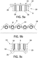
- FIG. 9a shows an embodiment of the device 19 for the harnessing of a water stream, illustrated as a rectangular front 18.
- the turbines are placed with their axes vertical, under the floating support 10, which is in turn supported by two hulls 20. Only the first turbine of each row is shown, the successive turbines are placed behind.
- FIG. 9c shows an embodiment of the device 19 analogous to that shown in FIG. 9a , but destined to harness the energy of a wind stream, and therefore the turbines are placed with their axes above the floating support.
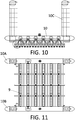
- FIGS. 10 to 12 show an embodiment of the invention comprising four rows, each provided with six successive turbines 9, arranged with their axes horizontal and in the same plane.
- the floating support 10 is basically a catamaran wherein the two hulls 10A, 10B support the axes of the turbines 9.
- Four rigid sails/ wings 10C fixed on the ends of the hulls 10A, 10B serve for orienting the base.
- the hulls 10A, 10B have floodable spaces inside that can extend in reservoirs placed inside the wings, which then contribute to control the water level.
- there are six turbines in each row it is obvious that more turbines can be provided to harness the maximum energy from the waves or current.
Landscapes
- Engineering & Computer Science (AREA)
- Chemical & Material Sciences (AREA)
- Combustion & Propulsion (AREA)
- Mechanical Engineering (AREA)
- General Engineering & Computer Science (AREA)
- Power Engineering (AREA)
- Other Liquid Machine Or Engine Such As Wave Power Use (AREA)
- Wind Motors (AREA)
- Surgical Instruments (AREA)
Claims (6)
- Vorrichtung (19) zur Umwandlung von kinetischer Energie aus einem Strom (16, 18) von Wellen oder Wasserströmungen in mechanische Rotationsenergie, aufweisend mehrere Querströmturbinen (9), von denen jede feststehende gekrümmte Turbinenschaufeln (5, 6) aufweist, die in einer Laufkäfig-Konfiguration um eine Rotationsachse (A) angeordnet sind, wobei die Turbinen (9) auf einem schwimmenden Träger (10) auf dem Wasser angebracht sind, so dass sie direkt in der Fluidströmung (18) positioniert werden können, und in Reihe hintereinander angeordnet sind, wobei ihre Achsen (A) zueinander parallel und senkrecht zum Strom (18) sind, wobei der schwimmende Träger (10) ein U-Querschnittprofil hat, das den Kanal bildet, so dass eine Bodenwand (12) und zwei Seitenwände (12A, 12B) definiert sind, wobei die Achsen (A) der Turbinen (9) drehbar zwischen den zwei Seitenwänden (12A, 12B) gelagert sind, und wobei die Schwimmsteuerungsmittel flutbare Schwimmer sind, so dass die Vorrichtung bewegbar ist zwischen einer tiefen Position, in welcher die Turbinen (9) vollständig versenkt sind, und einer höheren Position, in welcher die Turbinen (9) vollständig oberhalb des Wasserspiegels angeordnet sind.
- Vorrichtung nach Anspruch 1, wobei die Achsen (A) der Turbinen in der gleichen Ebene liegen.
- Vorrichtung nach einem der vorstehenden Ansprüche, wobei die Achsen (A) der Turbinen (9) in regelmäßigen Abständen angeordnet sind.
- Vorrichtung nach einem der vorstehenden Ansprüche, wobei der Schaufel-Satz der Turbinen (9) eine zylindrische Einhüllende hat.
- Vorrichtung nach einem der vorstehenden Ansprüche, wobei der Träger (10) Einrichtungen aufweist, um ihn im Gewässerbett zu verankern.
- Vorrichtung nach einem der vorstehenden Ansprüche, die keine Deflektoren oder Baffles aufweist.
Priority Applications (13)
| Application Number | Priority Date | Filing Date | Title |
|---|---|---|---|
| DK15382473.5T DK3150846T3 (en) | 2015-09-29 | 2015-09-29 | DEVICE FOR CONVERSION OF KINETIC ENERGY FROM A FLOW OF WAVES, WIND OR WATER CURRENTS FOR MECHANICAL ROTATION ENERGY |
| ES15382473T ES2718173T3 (es) | 2015-09-29 | 2015-09-29 | Dispositivo para convertir la energía cinética de un flujo de olas, viento o corrientes de agua en energía mecánica de rotación |
| EP15382473.5A EP3150846B1 (de) | 2015-09-29 | 2015-09-29 | Vorrichtung zur umwandlung von kinetischer energie aus einem strom aus wellen-, wind- oder wasserströmungen in mechanische drehenergie |
| PL15382473T PL3150846T3 (pl) | 2015-09-29 | 2015-09-29 | Urządzenie do przetwarzania energii kinetycznej z przepływu prądów fal, wiatru lub wody na mechaniczną energię obrotu |
| PT15382473T PT3150846T (pt) | 2015-09-29 | 2015-09-29 | Dispositivo para converter energia cinética de um fluxo de ondas, correntes de vento ou água em energia mecânica de rotação |
| PCT/ES2016/070474 WO2017055649A1 (es) | 2015-09-29 | 2016-06-23 | Dispositivo para convertir la energía cinética de las olas, las corrientes de agua o el viento en energía mecánica |
| CN201680062565.XA CN108350858A (zh) | 2015-09-29 | 2016-06-23 | 用于将波浪、水流或风力的动能转换为机械能的装置 |
| MX2018003722A MX2018003722A (es) | 2015-09-29 | 2016-06-23 | Dispositivo para convertir la energia cinetica de las olas, las corrientes de agua o el viento en energia mecanica. |
| JP2018535253A JP2018530708A (ja) | 2015-09-29 | 2016-06-23 | 波、風または水流からの運動エネルギーを機械的回転エネルギーに変換する装置 |
| US15/764,548 US10683840B2 (en) | 2015-09-29 | 2016-06-23 | Device for converting the kinetic energy of waves, water flows or wind into mechanical energy |
| AU2016329614A AU2016329614B2 (en) | 2015-09-29 | 2016-06-23 | Device for converting the kinetic energy of waves, water flows or wind into mechanical energy |
| CA3002254A CA3002254C (en) | 2015-09-29 | 2016-06-23 | Device for converting the kinetic energy of waves, water flows or wind into mechanical energy |
| CL2018000806A CL2018000806A1 (es) | 2015-09-29 | 2018-03-28 | Dispositivo para convertir la energía cinética de las olas, las corrientes de agua o el viento en energía mecánica |
Applications Claiming Priority (1)
| Application Number | Priority Date | Filing Date | Title |
|---|---|---|---|
| EP15382473.5A EP3150846B1 (de) | 2015-09-29 | 2015-09-29 | Vorrichtung zur umwandlung von kinetischer energie aus einem strom aus wellen-, wind- oder wasserströmungen in mechanische drehenergie |
Publications (2)
| Publication Number | Publication Date |
|---|---|
| EP3150846A1 EP3150846A1 (de) | 2017-04-05 |
| EP3150846B1 true EP3150846B1 (de) | 2018-12-26 |
Family
ID=54288736
Family Applications (1)
| Application Number | Title | Priority Date | Filing Date |
|---|---|---|---|
| EP15382473.5A Active EP3150846B1 (de) | 2015-09-29 | 2015-09-29 | Vorrichtung zur umwandlung von kinetischer energie aus einem strom aus wellen-, wind- oder wasserströmungen in mechanische drehenergie |
Country Status (13)
| Country | Link |
|---|---|
| US (1) | US10683840B2 (de) |
| EP (1) | EP3150846B1 (de) |
| JP (1) | JP2018530708A (de) |
| CN (1) | CN108350858A (de) |
| AU (1) | AU2016329614B2 (de) |
| CA (1) | CA3002254C (de) |
| CL (1) | CL2018000806A1 (de) |
| DK (1) | DK3150846T3 (de) |
| ES (1) | ES2718173T3 (de) |
| MX (1) | MX2018003722A (de) |
| PL (1) | PL3150846T3 (de) |
| PT (1) | PT3150846T (de) |
| WO (1) | WO2017055649A1 (de) |
Families Citing this family (5)
| Publication number | Priority date | Publication date | Assignee | Title |
|---|---|---|---|---|
| PE20220152A1 (es) * | 2019-03-08 | 2022-01-27 | Big Moon Power Inc | Sistemas y metodos para la generacion de potencia electrica de base hidroelectrica |
| CN110439730B (zh) * | 2019-08-02 | 2021-03-30 | 庄茜茜 | 增强型波浪发电装置 |
| CN112302873B (zh) * | 2020-10-19 | 2022-03-01 | 上海电气风电集团股份有限公司 | 海上漂浮式发电平台 |
| KR102293440B1 (ko) * | 2021-02-14 | 2021-08-25 | 이병찬 | 수류 및 풍력 겸용 발전장치 |
| CN112999855A (zh) * | 2021-04-15 | 2021-06-22 | 纪广波 | 一种废气处理设备 |
Family Cites Families (23)
| Publication number | Priority date | Publication date | Assignee | Title |
|---|---|---|---|---|
| US5136174A (en) * | 1990-11-20 | 1992-08-04 | Simoni Richard P | Multi-paddlewheel system for generating electricity from water canal |
| ES2074010B1 (es) | 1993-07-14 | 1998-05-16 | Univ Pais Vasco | Perfiles aerodinamicos de geometria sencilla |
| KR100191636B1 (ko) | 1995-12-23 | 1999-06-15 | 전성권 | 수력 발전 장치 |
| GB0329589D0 (en) * | 2003-12-20 | 2004-01-28 | Marine Current Turbines Ltd | Articulated false sea bed |
| US8403622B2 (en) * | 2005-02-09 | 2013-03-26 | Prime Energy Corporation | Radial-flow, horizontal-axis fluid turbine |
| PT1731757E (pt) * | 2005-06-07 | 2011-05-03 | Produtora De En El Ctrica Por Hidro Reaccao Unipessoal Lda Peehr | Catamar? com flutuadores perfilados suportando uma azenha de baixa queda e que tamb?m como ponte |
| US20090175723A1 (en) * | 2005-10-06 | 2009-07-09 | Broome Kenneth R | Undershot impulse jet driven water turbine having an improved vane configuration and radial gate for optimal hydroelectric power generation and water level control |
| US8350396B2 (en) * | 2009-03-17 | 2013-01-08 | Harry Edward Dempster | Water-current paddlewheel-based energy-generating unit having a tapered partial covering structure |
| WO2011101693A1 (en) * | 2010-02-22 | 2011-08-25 | Hidra Force D.O.O | Driving engine (water turbine) of hydrokinetic floating power plant with enhanced efficiency degree, and hydrokinetic floating power plant module |
| KR20110107881A (ko) * | 2010-03-26 | 2011-10-05 | 홍문표 | 바지선 위에 설치한 수평형 수차를 이용한 파력발전설비 |
| US8341957B2 (en) * | 2010-04-20 | 2013-01-01 | Joseph Erat S | Portable wave-swash and coastal-wind energy harvester |
| US20120007361A1 (en) * | 2010-07-09 | 2012-01-12 | Pete Agtuca | Water Handling Environment Water Electric Generator |
| GB2477872A (en) * | 2011-04-27 | 2011-08-17 | John Kendrick Skelton | Floating tidal stream electricity generating platform |
| US8525363B2 (en) * | 2011-07-27 | 2013-09-03 | Dlz Corporation | Horizontal-axis hydrokinetic water turbine system |
| US9086047B2 (en) * | 2011-09-17 | 2015-07-21 | Karim Salehpoor | Renewable energy extraction device |
| GB201119639D0 (en) * | 2011-11-15 | 2011-12-28 | Schepers Jos L M | Power station |
| US8772957B2 (en) * | 2011-11-23 | 2014-07-08 | John Herman Willingham | Power generating floating vessel |
| BE1021091B1 (nl) * | 2012-10-11 | 2015-11-27 | VAN ROMPAY BOUDEWIJN GABRIëL | Inrichting voor het opwekken van hydro-elektrische energie |
| DK2946107T3 (en) * | 2013-01-17 | 2019-04-23 | Rompay Boudewijn Gabriel Van | DEVICE FOR GENERATION OF HYDROELECTRIC ENERGY |
| KR101578537B1 (ko) * | 2013-10-18 | 2016-01-04 | 김유일 | 수면 부양식 고효율 수차 발전기 |
| KR101492768B1 (ko) | 2014-05-12 | 2015-02-12 | 한국해양대학교 산학협력단 | 횡류터빈을 이용한 부유식 파력발전장치 |
| KR101509729B1 (ko) * | 2014-08-26 | 2015-04-07 | 이재혁 | 조류발전장치 |
| US20170130690A1 (en) * | 2015-11-11 | 2017-05-11 | Edward Lilly | Barge electrical generation system |
-
2015
- 2015-09-29 EP EP15382473.5A patent/EP3150846B1/de active Active
- 2015-09-29 PT PT15382473T patent/PT3150846T/pt unknown
- 2015-09-29 DK DK15382473.5T patent/DK3150846T3/en active
- 2015-09-29 ES ES15382473T patent/ES2718173T3/es active Active
- 2015-09-29 PL PL15382473T patent/PL3150846T3/pl unknown
-
2016
- 2016-06-23 CA CA3002254A patent/CA3002254C/en active Active
- 2016-06-23 MX MX2018003722A patent/MX2018003722A/es unknown
- 2016-06-23 JP JP2018535253A patent/JP2018530708A/ja active Pending
- 2016-06-23 CN CN201680062565.XA patent/CN108350858A/zh active Pending
- 2016-06-23 WO PCT/ES2016/070474 patent/WO2017055649A1/es not_active Ceased
- 2016-06-23 US US15/764,548 patent/US10683840B2/en active Active
- 2016-06-23 AU AU2016329614A patent/AU2016329614B2/en not_active Ceased
-
2018
- 2018-03-28 CL CL2018000806A patent/CL2018000806A1/es unknown
Non-Patent Citations (1)
| Title |
|---|
| None * |
Also Published As
| Publication number | Publication date |
|---|---|
| JP2018530708A (ja) | 2018-10-18 |
| PL3150846T3 (pl) | 2019-10-31 |
| PT3150846T (pt) | 2019-04-01 |
| ES2718173T3 (es) | 2019-06-28 |
| US10683840B2 (en) | 2020-06-16 |
| DK3150846T3 (en) | 2019-04-08 |
| CA3002254C (en) | 2023-11-14 |
| AU2016329614A1 (en) | 2018-05-10 |
| US20180274516A1 (en) | 2018-09-27 |
| CL2018000806A1 (es) | 2018-06-08 |
| WO2017055649A1 (es) | 2017-04-06 |
| CA3002254A1 (en) | 2017-04-06 |
| EP3150846A1 (de) | 2017-04-05 |
| MX2018003722A (es) | 2018-11-09 |
| CN108350858A (zh) | 2018-07-31 |
| AU2016329614B2 (en) | 2020-10-22 |
Similar Documents
| Publication | Publication Date | Title |
|---|---|---|
| AU2016329614B2 (en) | Device for converting the kinetic energy of waves, water flows or wind into mechanical energy | |
| EP2659128B1 (de) | Energieerzeugungsverfahren und -vorrichtung | |
| AU746011B2 (en) | Extracting power from moving water | |
| US20110309624A1 (en) | Device and system for extracting tidal energy | |
| WO2015142737A1 (en) | Floating tower frame for ocean current turbine system | |
| US9309861B1 (en) | Ocean wave kinetic energy conversion method and system | |
| US20110187112A1 (en) | Hydro-kinetically powered electrical generator power head | |
| AU2018207025B2 (en) | Device and technique for generating power from moving water | |
| US9284941B2 (en) | Natural energy extraction apparatus | |
| GB2396888A (en) | Wind or water currect turbine | |
| US20120086208A1 (en) | Environmentally Safe Flowing Water and Air Energy Device With Power Output Optimization | |
| US20140138955A1 (en) | Vertical axis mooring rotor | |
| KR101261780B1 (ko) | 조류추동형 발전모듈 및 이를 포함하는 발전장치 | |
| KR101183378B1 (ko) | 소수력발전용 수차 | |
| GB2549283A (en) | Ocean wave kinetic energy conversion method and system | |
| EP2769087B1 (de) | Vorrichtung und verfahren zur gewinnung und speicherung von gezeitenenergie | |
| GB2503089A (en) | Device for recovering kinetic energy from a flowing fluid, eg from tidal or river currents | |
| BG109645A (bg) | Безнапорна водна турбина | |
| SK5510Y1 (en) | Flow turbine with pivoted blades |
Legal Events
| Date | Code | Title | Description |
|---|---|---|---|
| PUAI | Public reference made under article 153(3) epc to a published international application that has entered the european phase |
Free format text: ORIGINAL CODE: 0009012 |
|
| STAA | Information on the status of an ep patent application or granted ep patent |
Free format text: STATUS: THE APPLICATION HAS BEEN PUBLISHED |
|
| AK | Designated contracting states |
Kind code of ref document: A1 Designated state(s): AL AT BE BG CH CY CZ DE DK EE ES FI FR GB GR HR HU IE IS IT LI LT LU LV MC MK MT NL NO PL PT RO RS SE SI SK SM TR |
|
| AX | Request for extension of the european patent |
Extension state: BA ME |
|
| STAA | Information on the status of an ep patent application or granted ep patent |
Free format text: STATUS: REQUEST FOR EXAMINATION WAS MADE |
|
| 17P | Request for examination filed |
Effective date: 20171005 |
|
| RBV | Designated contracting states (corrected) |
Designated state(s): AL AT BE BG CH CY CZ DE DK EE ES FI FR GB GR HR HU IE IS IT LI LT LU LV MC MK MT NL NO PL PT RO RS SE SI SK SM TR |
|
| STAA | Information on the status of an ep patent application or granted ep patent |
Free format text: STATUS: EXAMINATION IS IN PROGRESS |
|
| 17Q | First examination report despatched |
Effective date: 20180104 |
|
| RAP1 | Party data changed (applicant data changed or rights of an application transferred) |
Owner name: ARRECIFE ENERGY SYSTEMS S.L. |
|
| RIN1 | Information on inventor provided before grant (corrected) |
Inventor name: ARRECIFE ENERGY SYSTEMS S.L. |
|
| GRAP | Despatch of communication of intention to grant a patent |
Free format text: ORIGINAL CODE: EPIDOSNIGR1 |
|
| STAA | Information on the status of an ep patent application or granted ep patent |
Free format text: STATUS: GRANT OF PATENT IS INTENDED |
|
| RIN1 | Information on inventor provided before grant (corrected) |
Inventor name: ARRECIFE ENERGY SYSTEMS S.L. |
|
| INTG | Intention to grant announced |
Effective date: 20180820 |
|
| RIN1 | Information on inventor provided before grant (corrected) |
Inventor name: DORIA IRIARTE, JOSE JAVIER |
|
| GRAS | Grant fee paid |
Free format text: ORIGINAL CODE: EPIDOSNIGR3 |
|
| GRAA | (expected) grant |
Free format text: ORIGINAL CODE: 0009210 |
|
| STAA | Information on the status of an ep patent application or granted ep patent |
Free format text: STATUS: THE PATENT HAS BEEN GRANTED |
|
| AK | Designated contracting states |
Kind code of ref document: B1 Designated state(s): AL AT BE BG CH CY CZ DE DK EE ES FI FR GB GR HR HU IE IS IT LI LT LU LV MC MK MT NL NO PL PT RO RS SE SI SK SM TR |
|
| REG | Reference to a national code |
Ref country code: GB Ref legal event code: FG4D |
|
| REG | Reference to a national code |
Ref country code: CH Ref legal event code: EP |
|
| REG | Reference to a national code |
Ref country code: AT Ref legal event code: REF Ref document number: 1081773 Country of ref document: AT Kind code of ref document: T Effective date: 20190115 |
|
| REG | Reference to a national code |
Ref country code: DE Ref legal event code: R096 Ref document number: 602015022201 Country of ref document: DE |
|
| REG | Reference to a national code |
Ref country code: IE Ref legal event code: FG4D |
|
| REG | Reference to a national code |
Ref country code: PT Ref legal event code: SC4A Ref document number: 3150846 Country of ref document: PT Date of ref document: 20190401 Kind code of ref document: T Free format text: AVAILABILITY OF NATIONAL TRANSLATION Effective date: 20190319 |
|
| REG | Reference to a national code |
Ref country code: DK Ref legal event code: T3 Effective date: 20190401 |
|
| REG | Reference to a national code |
Ref country code: SE Ref legal event code: TRGR |
|
| REG | Reference to a national code |
Ref country code: NL Ref legal event code: FP |
|
| PG25 | Lapsed in a contracting state [announced via postgrant information from national office to epo] |
Ref country code: LV Free format text: LAPSE BECAUSE OF FAILURE TO SUBMIT A TRANSLATION OF THE DESCRIPTION OR TO PAY THE FEE WITHIN THE PRESCRIBED TIME-LIMIT Effective date: 20181226 Ref country code: LT Free format text: LAPSE BECAUSE OF FAILURE TO SUBMIT A TRANSLATION OF THE DESCRIPTION OR TO PAY THE FEE WITHIN THE PRESCRIBED TIME-LIMIT Effective date: 20181226 Ref country code: BG Free format text: LAPSE BECAUSE OF FAILURE TO SUBMIT A TRANSLATION OF THE DESCRIPTION OR TO PAY THE FEE WITHIN THE PRESCRIBED TIME-LIMIT Effective date: 20190326 Ref country code: HR Free format text: LAPSE BECAUSE OF FAILURE TO SUBMIT A TRANSLATION OF THE DESCRIPTION OR TO PAY THE FEE WITHIN THE PRESCRIBED TIME-LIMIT Effective date: 20181226 |
|
| REG | Reference to a national code |
Ref country code: LT Ref legal event code: MG4D |
|
| REG | Reference to a national code |
Ref country code: NO Ref legal event code: T2 Effective date: 20181226 |
|
| PG25 | Lapsed in a contracting state [announced via postgrant information from national office to epo] |
Ref country code: RS Free format text: LAPSE BECAUSE OF FAILURE TO SUBMIT A TRANSLATION OF THE DESCRIPTION OR TO PAY THE FEE WITHIN THE PRESCRIBED TIME-LIMIT Effective date: 20181226 Ref country code: AL Free format text: LAPSE BECAUSE OF FAILURE TO SUBMIT A TRANSLATION OF THE DESCRIPTION OR TO PAY THE FEE WITHIN THE PRESCRIBED TIME-LIMIT Effective date: 20181226 |
|
| REG | Reference to a national code |
Ref country code: AT Ref legal event code: MK05 Ref document number: 1081773 Country of ref document: AT Kind code of ref document: T Effective date: 20181226 |
|
| REG | Reference to a national code |
Ref country code: ES Ref legal event code: FG2A Ref document number: 2718173 Country of ref document: ES Kind code of ref document: T3 Effective date: 20190628 |
|
| PG25 | Lapsed in a contracting state [announced via postgrant information from national office to epo] |
Ref country code: CZ Free format text: LAPSE BECAUSE OF FAILURE TO SUBMIT A TRANSLATION OF THE DESCRIPTION OR TO PAY THE FEE WITHIN THE PRESCRIBED TIME-LIMIT Effective date: 20181226 |
|
| PG25 | Lapsed in a contracting state [announced via postgrant information from national office to epo] |
Ref country code: SK Free format text: LAPSE BECAUSE OF FAILURE TO SUBMIT A TRANSLATION OF THE DESCRIPTION OR TO PAY THE FEE WITHIN THE PRESCRIBED TIME-LIMIT Effective date: 20181226 Ref country code: EE Free format text: LAPSE BECAUSE OF FAILURE TO SUBMIT A TRANSLATION OF THE DESCRIPTION OR TO PAY THE FEE WITHIN THE PRESCRIBED TIME-LIMIT Effective date: 20181226 Ref country code: SM Free format text: LAPSE BECAUSE OF FAILURE TO SUBMIT A TRANSLATION OF THE DESCRIPTION OR TO PAY THE FEE WITHIN THE PRESCRIBED TIME-LIMIT Effective date: 20181226 Ref country code: RO Free format text: LAPSE BECAUSE OF FAILURE TO SUBMIT A TRANSLATION OF THE DESCRIPTION OR TO PAY THE FEE WITHIN THE PRESCRIBED TIME-LIMIT Effective date: 20181226 |
|
| REG | Reference to a national code |
Ref country code: DE Ref legal event code: R097 Ref document number: 602015022201 Country of ref document: DE |
|
| PG25 | Lapsed in a contracting state [announced via postgrant information from national office to epo] |
Ref country code: AT Free format text: LAPSE BECAUSE OF FAILURE TO SUBMIT A TRANSLATION OF THE DESCRIPTION OR TO PAY THE FEE WITHIN THE PRESCRIBED TIME-LIMIT Effective date: 20181226 |
|
| PLBE | No opposition filed within time limit |
Free format text: ORIGINAL CODE: 0009261 |
|
| STAA | Information on the status of an ep patent application or granted ep patent |
Free format text: STATUS: NO OPPOSITION FILED WITHIN TIME LIMIT |
|
| 26N | No opposition filed |
Effective date: 20190927 |
|
| PG25 | Lapsed in a contracting state [announced via postgrant information from national office to epo] |
Ref country code: SI Free format text: LAPSE BECAUSE OF FAILURE TO SUBMIT A TRANSLATION OF THE DESCRIPTION OR TO PAY THE FEE WITHIN THE PRESCRIBED TIME-LIMIT Effective date: 20181226 |
|
| PG25 | Lapsed in a contracting state [announced via postgrant information from national office to epo] |
Ref country code: TR Free format text: LAPSE BECAUSE OF FAILURE TO SUBMIT A TRANSLATION OF THE DESCRIPTION OR TO PAY THE FEE WITHIN THE PRESCRIBED TIME-LIMIT Effective date: 20181226 |
|
| PG25 | Lapsed in a contracting state [announced via postgrant information from national office to epo] |
Ref country code: MC Free format text: LAPSE BECAUSE OF FAILURE TO SUBMIT A TRANSLATION OF THE DESCRIPTION OR TO PAY THE FEE WITHIN THE PRESCRIBED TIME-LIMIT Effective date: 20181226 |
|
| REG | Reference to a national code |
Ref country code: CH Ref legal event code: PL |
|
| PG25 | Lapsed in a contracting state [announced via postgrant information from national office to epo] |
Ref country code: CH Free format text: LAPSE BECAUSE OF NON-PAYMENT OF DUE FEES Effective date: 20190930 Ref country code: LI Free format text: LAPSE BECAUSE OF NON-PAYMENT OF DUE FEES Effective date: 20190930 Ref country code: LU Free format text: LAPSE BECAUSE OF NON-PAYMENT OF DUE FEES Effective date: 20190929 |
|
| PGFP | Annual fee paid to national office [announced via postgrant information from national office to epo] |
Ref country code: FI Payment date: 20200921 Year of fee payment: 6 Ref country code: IS Payment date: 20200910 Year of fee payment: 6 Ref country code: NL Payment date: 20200928 Year of fee payment: 6 |
|
| PGFP | Annual fee paid to national office [announced via postgrant information from national office to epo] |
Ref country code: IT Payment date: 20200922 Year of fee payment: 6 Ref country code: BE Payment date: 20200928 Year of fee payment: 6 Ref country code: PL Payment date: 20200915 Year of fee payment: 6 |
|
| PG25 | Lapsed in a contracting state [announced via postgrant information from national office to epo] |
Ref country code: CY Free format text: LAPSE BECAUSE OF FAILURE TO SUBMIT A TRANSLATION OF THE DESCRIPTION OR TO PAY THE FEE WITHIN THE PRESCRIBED TIME-LIMIT Effective date: 20181226 |
|
| PG25 | Lapsed in a contracting state [announced via postgrant information from national office to epo] |
Ref country code: GR Free format text: LAPSE BECAUSE OF FAILURE TO SUBMIT A TRANSLATION OF THE DESCRIPTION OR TO PAY THE FEE WITHIN THE PRESCRIBED TIME-LIMIT Effective date: 20181226 |
|
| PG25 | Lapsed in a contracting state [announced via postgrant information from national office to epo] |
Ref country code: HU Free format text: LAPSE BECAUSE OF FAILURE TO SUBMIT A TRANSLATION OF THE DESCRIPTION OR TO PAY THE FEE WITHIN THE PRESCRIBED TIME-LIMIT; INVALID AB INITIO Effective date: 20150929 Ref country code: MT Free format text: LAPSE BECAUSE OF FAILURE TO SUBMIT A TRANSLATION OF THE DESCRIPTION OR TO PAY THE FEE WITHIN THE PRESCRIBED TIME-LIMIT Effective date: 20181226 |
|
| REG | Reference to a national code |
Ref country code: FI Ref legal event code: MAE |
|
| PG25 | Lapsed in a contracting state [announced via postgrant information from national office to epo] |
Ref country code: FI Free format text: LAPSE BECAUSE OF NON-PAYMENT OF DUE FEES Effective date: 20210929 |
|
| REG | Reference to a national code |
Ref country code: NL Ref legal event code: MM Effective date: 20211001 |
|
| REG | Reference to a national code |
Ref country code: BE Ref legal event code: MM Effective date: 20210930 |
|
| PG25 | Lapsed in a contracting state [announced via postgrant information from national office to epo] |
Ref country code: NL Free format text: LAPSE BECAUSE OF NON-PAYMENT OF DUE FEES Effective date: 20211001 Ref country code: MK Free format text: LAPSE BECAUSE OF FAILURE TO SUBMIT A TRANSLATION OF THE DESCRIPTION OR TO PAY THE FEE WITHIN THE PRESCRIBED TIME-LIMIT Effective date: 20181226 |
|
| PG25 | Lapsed in a contracting state [announced via postgrant information from national office to epo] |
Ref country code: BE Free format text: LAPSE BECAUSE OF NON-PAYMENT OF DUE FEES Effective date: 20210930 |
|
| PG25 | Lapsed in a contracting state [announced via postgrant information from national office to epo] |
Ref country code: IT Free format text: LAPSE BECAUSE OF NON-PAYMENT OF DUE FEES Effective date: 20210929 |
|
| PG25 | Lapsed in a contracting state [announced via postgrant information from national office to epo] |
Ref country code: PL Free format text: LAPSE BECAUSE OF NON-PAYMENT OF DUE FEES Effective date: 20210929 |
|
| PGFP | Annual fee paid to national office [announced via postgrant information from national office to epo] |
Ref country code: DE Payment date: 20240918 Year of fee payment: 10 Ref country code: IE Payment date: 20240829 Year of fee payment: 10 |
|
| PGFP | Annual fee paid to national office [announced via postgrant information from national office to epo] |
Ref country code: DK Payment date: 20240829 Year of fee payment: 10 |
|
| PGFP | Annual fee paid to national office [announced via postgrant information from national office to epo] |
Ref country code: PT Payment date: 20240829 Year of fee payment: 10 |
|
| PGFP | Annual fee paid to national office [announced via postgrant information from national office to epo] |
Ref country code: FR Payment date: 20240827 Year of fee payment: 10 |
|
| PGFP | Annual fee paid to national office [announced via postgrant information from national office to epo] |
Ref country code: NO Payment date: 20240902 Year of fee payment: 10 Ref country code: SE Payment date: 20240829 Year of fee payment: 10 |
|
| PG25 | Lapsed in a contracting state [announced via postgrant information from national office to epo] |
Ref country code: IS Free format text: LAPSE BECAUSE OF NON-PAYMENT OF DUE FEES Effective date: 20220404 |
|
| PGFP | Annual fee paid to national office [announced via postgrant information from national office to epo] |
Ref country code: GB Payment date: 20250820 Year of fee payment: 11 |
|
| PGFP | Annual fee paid to national office [announced via postgrant information from national office to epo] |
Ref country code: ES Payment date: 20251003 Year of fee payment: 11 |