EP3150798A1 - Gas turbine disk - Google Patents
Gas turbine disk Download PDFInfo
- Publication number
- EP3150798A1 EP3150798A1 EP16180337.4A EP16180337A EP3150798A1 EP 3150798 A1 EP3150798 A1 EP 3150798A1 EP 16180337 A EP16180337 A EP 16180337A EP 3150798 A1 EP3150798 A1 EP 3150798A1
- Authority
- EP
- European Patent Office
- Prior art keywords
- gas turbine
- cooling channels
- turbine disk
- disk
- reinforcement parts
- Prior art date
- Legal status (The legal status is an assumption and is not a legal conclusion. Google has not performed a legal analysis and makes no representation as to the accuracy of the status listed.)
- Granted
Links
Images



Classifications
-
- F—MECHANICAL ENGINEERING; LIGHTING; HEATING; WEAPONS; BLASTING
- F01—MACHINES OR ENGINES IN GENERAL; ENGINE PLANTS IN GENERAL; STEAM ENGINES
- F01D—NON-POSITIVE DISPLACEMENT MACHINES OR ENGINES, e.g. STEAM TURBINES
- F01D5/00—Blades; Blade-carrying members; Heating, heat-insulating, cooling or antivibration means on the blades or the members
- F01D5/02—Blade-carrying members, e.g. rotors
- F01D5/08—Heating, heat-insulating or cooling means
- F01D5/081—Cooling fluid being directed on the side of the rotor disc or at the roots of the blades
- F01D5/082—Cooling fluid being directed on the side of the rotor disc or at the roots of the blades on the side of the rotor disc
-
- F—MECHANICAL ENGINEERING; LIGHTING; HEATING; WEAPONS; BLASTING
- F01—MACHINES OR ENGINES IN GENERAL; ENGINE PLANTS IN GENERAL; STEAM ENGINES
- F01D—NON-POSITIVE DISPLACEMENT MACHINES OR ENGINES, e.g. STEAM TURBINES
- F01D5/00—Blades; Blade-carrying members; Heating, heat-insulating, cooling or antivibration means on the blades or the members
- F01D5/02—Blade-carrying members, e.g. rotors
- F01D5/08—Heating, heat-insulating or cooling means
- F01D5/085—Heating, heat-insulating or cooling means cooling fluid circulating inside the rotor
- F01D5/087—Heating, heat-insulating or cooling means cooling fluid circulating inside the rotor in the radial passages of the rotor disc
-
- F—MECHANICAL ENGINEERING; LIGHTING; HEATING; WEAPONS; BLASTING
- F05—INDEXING SCHEMES RELATING TO ENGINES OR PUMPS IN VARIOUS SUBCLASSES OF CLASSES F01-F04
- F05D—INDEXING SCHEME FOR ASPECTS RELATING TO NON-POSITIVE-DISPLACEMENT MACHINES OR ENGINES, GAS-TURBINES OR JET-PROPULSION PLANTS
- F05D2220/00—Application
- F05D2220/30—Application in turbines
- F05D2220/32—Application in turbines in gas turbines
Definitions
- the present disclosure relates to a disk of a gas turbine and, more particularly, to a structure of a bore part of a gas turbine, in which a groove is provided to the bore part.
- a gas turbine in general, includes a compressor, a combustor and a turbine. Air is introduced through an air inlet and compressed by the compressor so as to be compressed air of high temperature and high pressure. Fuel is supplied with respect to the compressed air by the combustor so as to be burned. The combustion gas of high temperature and high pressure drives the turbine and thus drives a generator connected to this turbine.
- the turbine is formed of a plurality of stators and a plurality of rotors, which are arranged alternately, in a cabin, wherein the rotors are driven by the combustion gas so as to rotate an output shaft connected to the generator.
- the combustion gas which drives the turbine, is converted into static pressure by a diffuser in an exhaust cabin and then discharged into the atmosphere.
- cooling paths are formed in the stators and the rotors and a cooling medium is induced to flow through the cooling paths so as to cool the stators and the rotors, thereby securing heat resistance while facilitating the increase of the combustion gas temperature as well as improving an output and efficiency.
- a turbine disk 10 has a cooling channel 11 formed along the diameter direction thereof and the front end portion of the cooling channel communicates with a cooling path 12 of a stator main body.
- a cooling medium is supplied from a base part with respect to the cooling channel and flows through this cooling channel, thereby cooling the main body of a rotor 20.
- the present disclosure has been made to solve the above-mentioned problems occurring in the related art, and it is an objective of the present disclosure to provide a gas turbine disk, in which a reinforcement part is provided to a cooling channel of a gas turbine disk so as to induce stress decrease at a position where the stress has been conventionally concentrated in the circumferential direction or the diameter direction of the turbine disk, thereby improving or maximizing the lifespan of the disk.
- the object is solved by the features of the independent claim.
- a gas turbine disk comprises: a plurality of cooling channels penetrating side surfaces of the disks and spaced from each other in a radial direction; and reinforcement parts coupled to partial arcs of exits of the cooling channels so as to reduce stress concentrated on the cooling channels.
- a plurality of blades may be arranged on outer circumferential surfaces of the plurality of disks.
- the reinforcement part may be formed in a polygonal or circular shape so as to entirely encompass the exit of a cooling channel.
- the reinforcement part may protrude in the axial direction of a disk.
- the reinforcement part may be formed to directly connect one cooling channel to another cooling channel, which is adjacent to the one cooling channel.
- the reinforcement part may protrude in the axial direction of a disk.
- the reinforcement part may continuously encompass the exit of a cooling channel along the circumferential surface of the exit of the cooling channel.
- reinforcement parts may be continuously formed along the circumference formed by the exits of a plurality of cooling channels.
- reinforcement parts may be formed in the shape of a circle, a rectangle or any other polygon.
- the reinforcement part may be provided to the cooling channel of the disk of a gas turbine so as to induce the decrease of stress concentration, thereby increasing the lifespan of the disk.
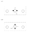
- Fig. 3 shows cooling channels and reinforcement parts forming a disk of a gas turbine according to an embodiment of the present disclosure.
- Fig. 4 shows cooling channels and reinforcement parts forming a disk of a gas turbine according to another embodiment of the present disclosure
- Fig. 5 shows cooling channels and reinforcement parts of a disk of a gas turbine according to still another embodiment of the present disclosure.
- a gas turbine disk may include a disk 100, on which outer circumferential surfaces one or more blades may be arranged, a plurality of cooling channels 110 penetrating side surfaces of the disk 100 and are spaced from each other in a radial direction, and reinforcement parts 120 coupled to partial arcs 111 of exits of the cooling channels 110 so as to reduce stress concentrated on the cooling channels 110.
- a gas turbine may include a plurality fo the gas turbine disks and a plurality of blades. The plurality of blades may be arranged at outer circumferential surfaces of the plurality of disks.
- the cooling channels 110 may be formed penetrating the disk 100 in parallel to the axial direction of the disk 100. That is, the cooling channels 110 are formed through one surface and the other surface of the disk 100 in the axial direction.
- the cooling channels 110 may be hollow parts, each of having a cross section in a circular shape.
- the cooling channels 110 may be formed as hollow parts, each of which having a cross section in an oval shape so as to have a long axis in the circumferential direction of the disk 100 or in the radial direction of the disk 100.
- the cooling channels 110 are to enable a cooling medium such as air, steam and the like to flow through the cooling channels 110 so as to cool a stator and a rotor, thereby securing heat resistance while facilitating the increase of combustion gas temperature as well as improving an output and efficiency.
- a cooling medium such as air, steam and the like
- the reinforcement parts 120 may be formed in a buildup shape so as to reinforce the cooling channels in the axial direction and in the radial direction.
- the reinforcement part 120 may be formed in a continuous shape, in which the reinforcement part 120 extends from one end thereof, which is formed at a partial arc 111 of the exit of one cooling channel 110, to the other end, which is formed at a partial arc 111 of the exit of another one cooling channel 110 that is adjacent to the one cooling channel 110. Therefore, the reinforcement parts 120 are formed in a shape, in which the reinforcement parts 120 connect the exits of the cooling channels, which are adjacent to each other, among the plurality of cooling channels.
- the shape, in which the respective reinforcement parts 120 and the cooling channels 110 are formed to be continuously connected may be the shape of a chain when viewing the side surface of the disk 100 on the whole.
- the above described embodiment may be applied for the reinforcement when the stress is concentrated in the circumferential direction 1 la of the disk 100.
- the reinforcement part 120 may be formed to directly connect one cooling channel 110 to another cooling channel 110, which is adjacent to the one cooling channel 110, wherein this reinforcement part 120 may be formed to be protruded in the axial direction of the disk 100.
- the reinforcement parts 120 may be protruded up to a preferable level according to the degree of the stress applied to the cooling channels 110.
- the reinforcement part 120 may continuously encompass the exit of the cooling channel 110 along the circumferential surface of the exit, so as to cope with the stress concentrated in the circumferential direction 11a of the disk 100 as well as the stress concentrated in the diameter direction 11b of the disk 100.
- the protrusion shape may be variously formed, wherein the thickness of the protrusion is preferably formed according to the stress concentration degree in the same way as the embodiment shown in Fig. 3 .
- the reinforcement part 120 is formed in a polygonal or circular shape so as to entirely encompass the exit, and may be formed to be protruded in the axial direction of the disk 100.
- This feature is to make the reinforcement at a position where rigidity reinforcement is most necessary according to the shape of a cooling concentration portion.
- the reinforcement part is in a shape, in which the length in the diameter direction of the disk is long so as to correspond to the stress in the diameter direction 11b.
- the gas turbine disk 100 is provided with the reinforcement parts 120 as the protruded buildup parts at the portions to which the stress is concentrated, thereby inducing the decrease of the local peak stress and increasing the low cycle fatigue (LCF) lifespan without requiring laser shock peening (LSP) thereby reducing additional manufacturing processes and reducing the associated manufacturing costs.
- the buildup parts, that is, the reinforcement parts 120 may be differently applied to the portions according to whether the circumference direction stress (radial peak stress) or the diameter direction stress (tangential peak stress) is applied thereto, thereby maximizing the effect.
Landscapes
- Engineering & Computer Science (AREA)
- Mechanical Engineering (AREA)
- General Engineering & Computer Science (AREA)
- Turbine Rotor Nozzle Sealing (AREA)
Abstract
Description
- The present disclosure relates to a disk of a gas turbine and, more particularly, to a structure of a bore part of a gas turbine, in which a groove is provided to the bore part.
- In general, a gas turbine includes a compressor, a combustor and a turbine. Air is introduced through an air inlet and compressed by the compressor so as to be compressed air of high temperature and high pressure. Fuel is supplied with respect to the compressed air by the combustor so as to be burned. The combustion gas of high temperature and high pressure drives the turbine and thus drives a generator connected to this turbine.
- The turbine is formed of a plurality of stators and a plurality of rotors, which are arranged alternately, in a cabin, wherein the rotors are driven by the combustion gas so as to rotate an output shaft connected to the generator. In addition, the combustion gas, which drives the turbine, is converted into static pressure by a diffuser in an exhaust cabin and then discharged into the atmosphere.
- According to recent demands for a gas turbine of a high output and high efficiency, there is a tendency that the temperature of the combustion gas induced into the stators and the rotors is gradually increased. Therefore, typically, cooling paths are formed in the stators and the rotors and a cooling medium is induced to flow through the cooling paths so as to cool the stators and the rotors, thereby securing heat resistance while facilitating the increase of the combustion gas temperature as well as improving an output and efficiency.
- Referring to
Fig. 1 , aturbine disk 10 has acooling channel 11 formed along the diameter direction thereof and the front end portion of the cooling channel communicates with acooling path 12 of a stator main body. In addition, a cooling medium is supplied from a base part with respect to the cooling channel and flows through this cooling channel, thereby cooling the main body of arotor 20. - However, such a cooling channel respectively has a portion to which stress is concentrated in the circumferential direction or the diameter direction of the turbine disk. Therefore, there is a problem that the tensile stress has to be minimized.
- Accordingly, the present disclosure has been made to solve the above-mentioned problems occurring in the related art, and it is an objective of the present disclosure to provide a gas turbine disk, in which a reinforcement part is provided to a cooling channel of a gas turbine disk so as to induce stress decrease at a position where the stress has been conventionally concentrated in the circumferential direction or the diameter direction of the turbine disk, thereby improving or maximizing the lifespan of the disk. The object is solved by the features of the independent claim.
- According to one embodiment, a gas turbine disk comprises: a plurality of cooling channels penetrating side surfaces of the disks and spaced from each other in a radial direction; and reinforcement parts coupled to partial arcs of exits of the cooling channels so as to reduce stress concentrated on the cooling channels. In a plurality of disks, a plurality of blades may be arranged on outer circumferential surfaces of the plurality of disks.
- According to an embodiment of the present disclosure, the reinforcement part may be formed in a polygonal or circular shape so as to entirely encompass the exit of a cooling channel. The reinforcement part may protrude in the axial direction of a disk.
- According to an embodiment of the present disclosure, the reinforcement part may be formed to directly connect one cooling channel to another cooling channel, which is adjacent to the one cooling channel. The reinforcement part may protrude in the axial direction of a disk.
- According to an embodiment of the present disclosure, the reinforcement part may continuously encompass the exit of a cooling channel along the circumferential surface of the exit of the cooling channel.
- According to an embodiment of the present disclosure, reinforcement parts may be continuously formed along the circumference formed by the exits of a plurality of cooling channels.
- According to an embodiment of the present disclosure, reinforcement parts may be formed in the shape of a circle, a rectangle or any other polygon.
- According to the present invention as described above, the reinforcement part may be provided to the cooling channel of the disk of a gas turbine so as to induce the decrease of stress concentration, thereby increasing the lifespan of the disk.
-
-
Fig. 1 is a partial cross-sectional view of a related art gas turbine disk. -
Fig. 2A is a partial cross-sectional view of a cooling channel of a gas turbine disk. -
Fig. 2B is a partial cross-sectional view of a cooling channel of a gas turbine disk. -
Fig. 3 is a side view of cooling channels and reinforcement parts forming a disk of a gas turbine according to an embodiment of the present disclosure. -
Fig. 4 is a side view of cooling channels and reinforcement parts forming a disk of a gas turbine according to another embodiment of the present disclosure, and -
Fig. 5 is a perspective view of cooling channels and reinforcement parts of a disk of a gas turbine according to still another embodiment of the present disclosure. - Reference will be now made in detail to the preferred embodiments of the present disclosure with reference to the attached illustrative drawings. It should be noted that, in adding reference signs to the constituent elements in each of the drawings, the same constituent elements have the same reference signs even though they are illustrated in different figures. In addition, in the description of the present disclosure, when it is judged that detailed descriptions of known functions or structures may make the essential points vague, the detailed descriptions of the known functions or structures will be omitted.
- Further, in the description of the constituent elements of the embodiments of the present disclosure, it is possible to use terms such as first, second, A, B, (a), (b) and the like. These terms are just to distinguish the constituent elements from any other constituent elements but do not limit the nature or sequence or order and the like of corresponding features by the terms. Additionally, it should be also understood that the expression that some constituent element is "connected", "coupled" or "joined" to another constituent element means that some constituent element may be directly connected or joined to another constituent element or is also "connected", "coupled" or "joined" to another constituent element through a further component therebetween.
-
Fig. 3 shows cooling channels and reinforcement parts forming a disk of a gas turbine according to an embodiment of the present disclosure. -
Fig. 4 shows cooling channels and reinforcement parts forming a disk of a gas turbine according to another embodiment of the present disclosure, and -
Fig. 5 shows cooling channels and reinforcement parts of a disk of a gas turbine according to still another embodiment of the present disclosure. -
- 100 : disk
- 110 : cooling channel
- 111 : partial arc
- 120 : reinforcement part
- As shown in
Fig.3 , a gas turbine disk according to an embodiment of the present disclosure may include adisk 100, on which outer circumferential surfaces one or more blades may be arranged, a plurality ofcooling channels 110 penetrating side surfaces of thedisk 100 and are spaced from each other in a radial direction, andreinforcement parts 120 coupled topartial arcs 111 of exits of thecooling channels 110 so as to reduce stress concentrated on thecooling channels 110. It will be appreciated that a gas turbine may include a plurality fo the gas turbine disks and a plurality of blades. The plurality of blades may be arranged at outer circumferential surfaces of the plurality of disks. - The
cooling channels 110 may be formed penetrating thedisk 100 in parallel to the axial direction of thedisk 100. That is, thecooling channels 110 are formed through one surface and the other surface of thedisk 100 in the axial direction. - The
cooling channels 110 may be hollow parts, each of having a cross section in a circular shape. In addition, in order to prevent or reduce the concentration of stress, thecooling channels 110 may be formed as hollow parts, each of which having a cross section in an oval shape so as to have a long axis in the circumferential direction of thedisk 100 or in the radial direction of thedisk 100. - The
cooling channels 110 are to enable a cooling medium such as air, steam and the like to flow through thecooling channels 110 so as to cool a stator and a rotor, thereby securing heat resistance while facilitating the increase of combustion gas temperature as well as improving an output and efficiency. - The
reinforcement parts 120 may be formed in a buildup shape so as to reinforce the cooling channels in the axial direction and in the radial direction. - The
reinforcement part 120 according to an embodiment of the present disclosure, as shown inFig. 3 , may be formed in a continuous shape, in which thereinforcement part 120 extends from one end thereof, which is formed at apartial arc 111 of the exit of onecooling channel 110, to the other end, which is formed at apartial arc 111 of the exit of another onecooling channel 110 that is adjacent to the onecooling channel 110. Therefore, thereinforcement parts 120 are formed in a shape, in which thereinforcement parts 120 connect the exits of the cooling channels, which are adjacent to each other, among the plurality of cooling channels. - That is, the shape, in which the
respective reinforcement parts 120 and thecooling channels 110 are formed to be continuously connected, may be the shape of a chain when viewing the side surface of thedisk 100 on the whole. - The above described embodiment, as shown in
Fig. 2 , may be applied for the reinforcement when the stress is concentrated in the circumferential direction 1 la of thedisk 100. - Further, as shown in
Fig. 4 , thereinforcement part 120 may be formed to directly connect onecooling channel 110 to anothercooling channel 110, which is adjacent to the onecooling channel 110, wherein thisreinforcement part 120 may be formed to be protruded in the axial direction of thedisk 100. - The
reinforcement parts 120 may be protruded up to a preferable level according to the degree of the stress applied to the coolingchannels 110. - In addition, according to the embodiment, as shown in
Fig. 3 , thereinforcement part 120 may continuously encompass the exit of thecooling channel 110 along the circumferential surface of the exit, so as to cope with the stress concentrated in thecircumferential direction 11a of thedisk 100 as well as the stress concentrated in thediameter direction 11b of thedisk 100. - The protrusion shape may be variously formed, wherein the thickness of the protrusion is preferably formed according to the stress concentration degree in the same way as the embodiment shown in
Fig. 3 . - Referring to
Fig. 5 , thereinforcement part 120 is formed in a polygonal or circular shape so as to entirely encompass the exit, and may be formed to be protruded in the axial direction of thedisk 100. - This feature is to make the reinforcement at a position where rigidity reinforcement is most necessary according to the shape of a cooling concentration portion.
- According to the embodiment of the present disclosure, as shown in
Fig. 5 , the reinforcement part is in a shape, in which the length in the diameter direction of the disk is long so as to correspond to the stress in thediameter direction 11b. - The
gas turbine disk 100 according to the embodiment of the present embodiment is provided with thereinforcement parts 120 as the protruded buildup parts at the portions to which the stress is concentrated, thereby inducing the decrease of the local peak stress and increasing the low cycle fatigue (LCF) lifespan without requiring laser shock peening (LSP) thereby reducing additional manufacturing processes and reducing the associated manufacturing costs. In addition, the buildup parts, that is, thereinforcement parts 120 may be differently applied to the portions according to whether the circumference direction stress (radial peak stress) or the diameter direction stress (tangential peak stress) is applied thereto, thereby maximizing the effect. - Hereinabove, even though all of the constituent elements are coupled into one body or operate in a combined state in the description of the above-mentioned embodiments of the present disclosure, the present disclosure is not limited to these embodiments. That is, all of the constituent elements may operate in one or more selective combination within the range of the purpose of the present invention. It should be also understood that the terms of "include", "comprise" or "have" in the specification are "open type" expressions just to say that the corresponding constituent elements exit and, unless specifically described to the contrary, do not exclude but may include additional components.
- All terms, including technical or scientific terms, unless otherwise defined, have the same meaning as commonly understood by those of ordinary skill in the art, to which the present invention belongs. The terms which are commonly used such as the definitions in the dictionary are to be interpreted to represent the meaning that matches the meaning in the context of the relevant art and, unless otherwise defined explicitly in the present invention, it shall not be interpreted to have an idealistic or excessively formalistic meaning.
- As described above, while the present invention has been particularly shown and described with reference to the example embodiments thereof, it will be understood by those of ordinary skill in the art that the above embodiments of the present invention are all exemplified and various changes, modifications and equivalents may be made therein without changing the essential characteristics and scope of the present invention.
- The embodiments discussed have been presented by way of example only and not limitation. Thus, the breadth and scope of the invention(s) should not be limited by any of the above-described exemplary embodiments, but should be defined only in accordance with the following claims and their equivalents. Moreover, the above advantages and features are provided in described embodiments, but shall not limit the application of the claims to processes and structures accomplishing any or all of the above advantages.
Claims (8)
- A gas turbine disk, comprising:a plurality of cooling channels penetrating a side surface of the disk and spaced from each other in a radial direction; andreinforcement parts coupled to partial arcs of exits of the cooling channels so as to reduce stress concentrated on the cooling channels.
- The gas turbine disk according to claim 1, wherein at least one of the reinforcement parts is configured to entirely encompass the exit of the corresponding cooling channel.
- The gas turbine disk according to claim 1 or 2, wherein at least one of the reinforcement part is formed in a polygonal or circular shape.
- The gas turbine disk according to any one of the preceding claims, wherein the reinforcement parts protrude in an axial direction of the disk.
- The gas turbine disk according to any one of the preceding claims, wherein the reinforcement parts respectively connect exits of neighboring cooling channels among the plurality of cooling channels.
- The gas turbine disk according to any one of the preceding claims, wherein at least one of the reinforcement parts continuously encompasses the exit of the corresponding cooling channel along a circumferential surface of the exit of said cooling channel.
- The gas turbine disk according to any one of the preceding claims, wherein the reinforcement parts are continuously formed along a circumference formed by the exits of the plurality of cooling channels.
- A gas turbine, comprising:a plurality of disks according to any one of the preceding claims; anda plurality of blades arranged on outer circumferential surfaces of the disks.
Applications Claiming Priority (1)
| Application Number | Priority Date | Filing Date | Title |
|---|---|---|---|
| KR1020150139136A KR101663306B1 (en) | 2015-10-02 | 2015-10-02 | Gas Turbine disk |
Publications (2)
| Publication Number | Publication Date |
|---|---|
| EP3150798A1 true EP3150798A1 (en) | 2017-04-05 |
| EP3150798B1 EP3150798B1 (en) | 2021-06-16 |
Family
ID=56497653
Family Applications (1)
| Application Number | Title | Priority Date | Filing Date |
|---|---|---|---|
| EP16180337.4A Active EP3150798B1 (en) | 2015-10-02 | 2016-07-20 | Gas turbine disk |
Country Status (4)
| Country | Link |
|---|---|
| US (1) | US10605085B2 (en) |
| EP (1) | EP3150798B1 (en) |
| KR (1) | KR101663306B1 (en) |
| WO (1) | WO2017057994A1 (en) |
Cited By (1)
| Publication number | Priority date | Publication date | Assignee | Title |
|---|---|---|---|---|
| EP3889390A1 (en) * | 2020-03-30 | 2021-10-06 | ITP Engines UK Ltd | Rotatable forged disc for a bladed rotor wheel and a method for manufacturing thereof |
Families Citing this family (1)
| Publication number | Priority date | Publication date | Assignee | Title |
|---|---|---|---|---|
| AU2016277549B2 (en) * | 2016-10-24 | 2018-10-18 | Intex Holdings Pty Ltd | A multi-stage axial flow turbine adapted to operate at low steam temperatures |
Citations (5)
| Publication number | Priority date | Publication date | Assignee | Title |
|---|---|---|---|---|
| JPS62225701A (en) * | 1986-03-28 | 1987-10-03 | Toshiba Corp | Steam turbine |
| EP1450005A1 (en) * | 2003-02-14 | 2004-08-25 | Snecma Moteurs | Turbine discs cooling device |
| US20060120855A1 (en) * | 2004-12-03 | 2006-06-08 | Pratt & Whitney Canada Corp. | Rotor assembly with cooling air deflectors and method |
| WO2010088882A2 (en) * | 2009-02-04 | 2010-08-12 | Mtu Aero Engines Gmbh | Integrally bladed rotor disk for a turbine |
| DE102011100221A1 (en) * | 2011-05-02 | 2012-11-08 | Mtu Aero Engines Gmbh | Covering device, integrally bladed rotor body, method and turbomachine |
Family Cites Families (14)
| Publication number | Priority date | Publication date | Assignee | Title |
|---|---|---|---|---|
| US3343806A (en) * | 1965-05-27 | 1967-09-26 | Gen Electric | Rotor assembly for gas turbine engines |
| JPS58143101A (en) * | 1982-02-22 | 1983-08-25 | Toshiba Corp | Steam turbine |
| JPS6093101A (en) | 1983-10-28 | 1985-05-24 | Hitachi Ltd | Apparatus for preventing rotor of steam turbine from temperature rise |
| JP3308316B2 (en) * | 1992-09-11 | 2002-07-29 | 三井化学株式会社 | Amorphous polyimide and method for producing the same |
| US6185924B1 (en) * | 1997-10-17 | 2001-02-13 | Hitachi, Ltd. | Gas turbine with turbine blade cooling |
| DE60043965D1 (en) | 1999-06-16 | 2010-04-22 | Gen Electric | Gas turbine rotor with axially directed cooling tubes |
| JP2001234701A (en) * | 2000-02-25 | 2001-08-31 | Hitachi Ltd | Refrigerant recovery type gas turbine rotor |
| US6506021B1 (en) * | 2001-10-31 | 2003-01-14 | General Electric Company | Cooling system for a gas turbine |
| US7160078B2 (en) * | 2004-09-23 | 2007-01-09 | General Electric Company | Mechanical solution for rail retention of turbine nozzles |
| JP4939461B2 (en) * | 2008-02-27 | 2012-05-23 | 三菱重工業株式会社 | Turbine disc and gas turbine |
| FR2931873B1 (en) * | 2008-05-29 | 2010-08-20 | Snecma | A TURBINE DISK ASSEMBLY OF A GAS TURBINE ENGINE AND A BEARING BRIDGE SUPPORT CIRCUIT, COOLING CIRCUIT OF A TURBINE DISK OF SUCH AN ASSEMBLY. |
| DE102015219022A1 (en) * | 2015-10-01 | 2017-04-06 | Rolls-Royce Deutschland Ltd & Co Kg | Flow guiding device and turbomachine with at least one flow guiding device |
| JP6686733B2 (en) | 2016-06-23 | 2020-04-22 | コニカミノルタ株式会社 | Dynamic analysis system |
| JP7123315B2 (en) | 2018-02-23 | 2022-08-23 | ユニマテック株式会社 | Composite particles |
-
2015
- 2015-10-02 KR KR1020150139136A patent/KR101663306B1/en active Active
-
2016
- 2016-07-15 US US15/212,133 patent/US10605085B2/en active Active
- 2016-07-20 EP EP16180337.4A patent/EP3150798B1/en active Active
- 2016-10-04 WO PCT/KR2016/011072 patent/WO2017057994A1/en not_active Ceased
Patent Citations (5)
| Publication number | Priority date | Publication date | Assignee | Title |
|---|---|---|---|---|
| JPS62225701A (en) * | 1986-03-28 | 1987-10-03 | Toshiba Corp | Steam turbine |
| EP1450005A1 (en) * | 2003-02-14 | 2004-08-25 | Snecma Moteurs | Turbine discs cooling device |
| US20060120855A1 (en) * | 2004-12-03 | 2006-06-08 | Pratt & Whitney Canada Corp. | Rotor assembly with cooling air deflectors and method |
| WO2010088882A2 (en) * | 2009-02-04 | 2010-08-12 | Mtu Aero Engines Gmbh | Integrally bladed rotor disk for a turbine |
| DE102011100221A1 (en) * | 2011-05-02 | 2012-11-08 | Mtu Aero Engines Gmbh | Covering device, integrally bladed rotor body, method and turbomachine |
Cited By (2)
| Publication number | Priority date | Publication date | Assignee | Title |
|---|---|---|---|---|
| EP3889390A1 (en) * | 2020-03-30 | 2021-10-06 | ITP Engines UK Ltd | Rotatable forged disc for a bladed rotor wheel and a method for manufacturing thereof |
| US11530613B2 (en) | 2020-03-30 | 2022-12-20 | Itp Engines Uk Ltd | Rotatable forged disc for a bladed rotor wheel and a method for manufacturing thereof |
Also Published As
| Publication number | Publication date |
|---|---|
| US10605085B2 (en) | 2020-03-31 |
| EP3150798B1 (en) | 2021-06-16 |
| KR101663306B1 (en) | 2016-10-06 |
| US20170096899A1 (en) | 2017-04-06 |
| WO2017057994A1 (en) | 2017-04-06 |
Similar Documents
| Publication | Publication Date | Title |
|---|---|---|
| US9995149B2 (en) | Structural configurations and cooling circuits in turbine blades | |
| EP2823151B1 (en) | Airfoil with improved internal cooling channel pedestals | |
| US9822647B2 (en) | High chord bucket with dual part span shrouds and curved dovetail | |
| US11732593B2 (en) | Flared central cavity aft of airfoil leading edge | |
| EP1939411A2 (en) | Cantilevered nozzle with crowned flange to improve outer band low cycle fatigue | |
| US9879542B2 (en) | Platform with curved edges adjacent suction side of airfoil | |
| US9581085B2 (en) | Hot streak alignment for gas turbine durability | |
| US10605090B2 (en) | Intermediate central passage spanning outer walls aft of airfoil leading edge passage | |
| US9879547B2 (en) | Interior cooling circuits in turbine blades | |
| US9739159B2 (en) | Method and system for relieving turbine rotor blade dovetail stress | |
| JP2016125484A (en) | Interior cooling channels in turbine blades | |
| US20150096306A1 (en) | Gas turbine airfoil with cooling enhancement | |
| EP3150798B1 (en) | Gas turbine disk | |
| US10533424B2 (en) | Gas turbine engine rotor mistuning | |
| US9765631B2 (en) | Structural configurations and cooling circuits in turbine blades | |
| US10053990B2 (en) | Internal rib with defined concave surface curvature for airfoil | |
| EP2612989A2 (en) | System and method for reducing stress in a rotor | |
| US20130022444A1 (en) | Low pressure turbine exhaust diffuser with turbulators | |
| US20170284415A1 (en) | Fan housing and engine assembly with fan housing | |
| US20160186577A1 (en) | Cooling configurations for turbine blades | |
| EP3203026B1 (en) | Gas turbine blade with pedestal array | |
| JP2016539273A (en) | Turbine blade |
Legal Events
| Date | Code | Title | Description |
|---|---|---|---|
| PUAI | Public reference made under article 153(3) epc to a published international application that has entered the european phase |
Free format text: ORIGINAL CODE: 0009012 |
|
| STAA | Information on the status of an ep patent application or granted ep patent |
Free format text: STATUS: REQUEST FOR EXAMINATION WAS MADE |
|
| 17P | Request for examination filed |
Effective date: 20160720 |
|
| AK | Designated contracting states |
Kind code of ref document: A1 Designated state(s): AL AT BE BG CH CY CZ DE DK EE ES FI FR GB GR HR HU IE IS IT LI LT LU LV MC MK MT NL NO PL PT RO RS SE SI SK SM TR |
|
| AX | Request for extension of the european patent |
Extension state: BA ME |
|
| RBV | Designated contracting states (corrected) |
Designated state(s): AL AT BE BG CH CY CZ DE DK EE ES FI FR GB GR HR HU IE IS IT LI LT LU LV MC MK MT NL NO PL PT RO RS SE SI SK SM TR |
|
| STAA | Information on the status of an ep patent application or granted ep patent |
Free format text: STATUS: EXAMINATION IS IN PROGRESS |
|
| 17Q | First examination report despatched |
Effective date: 20200703 |
|
| GRAP | Despatch of communication of intention to grant a patent |
Free format text: ORIGINAL CODE: EPIDOSNIGR1 |
|
| STAA | Information on the status of an ep patent application or granted ep patent |
Free format text: STATUS: GRANT OF PATENT IS INTENDED |
|
| INTG | Intention to grant announced |
Effective date: 20210113 |
|
| GRAS | Grant fee paid |
Free format text: ORIGINAL CODE: EPIDOSNIGR3 |
|
| GRAA | (expected) grant |
Free format text: ORIGINAL CODE: 0009210 |
|
| STAA | Information on the status of an ep patent application or granted ep patent |
Free format text: STATUS: THE PATENT HAS BEEN GRANTED |
|
| AK | Designated contracting states |
Kind code of ref document: B1 Designated state(s): AL AT BE BG CH CY CZ DE DK EE ES FI FR GB GR HR HU IE IS IT LI LT LU LV MC MK MT NL NO PL PT RO RS SE SI SK SM TR |
|
| REG | Reference to a national code |
Ref country code: GB Ref legal event code: FG4D |
|
| REG | Reference to a national code |
Ref country code: CH Ref legal event code: EP |
|
| REG | Reference to a national code |
Ref country code: DE Ref legal event code: R096 Ref document number: 602016059298 Country of ref document: DE |
|
| REG | Reference to a national code |
Ref country code: AT Ref legal event code: REF Ref document number: 1402476 Country of ref document: AT Kind code of ref document: T Effective date: 20210715 |
|
| REG | Reference to a national code |
Ref country code: IE Ref legal event code: FG4D |
|
| REG | Reference to a national code |
Ref country code: LT Ref legal event code: MG9D |
|
| PG25 | Lapsed in a contracting state [announced via postgrant information from national office to epo] |
Ref country code: HR Free format text: LAPSE BECAUSE OF FAILURE TO SUBMIT A TRANSLATION OF THE DESCRIPTION OR TO PAY THE FEE WITHIN THE PRESCRIBED TIME-LIMIT Effective date: 20210616 Ref country code: BG Free format text: LAPSE BECAUSE OF FAILURE TO SUBMIT A TRANSLATION OF THE DESCRIPTION OR TO PAY THE FEE WITHIN THE PRESCRIBED TIME-LIMIT Effective date: 20210916 Ref country code: FI Free format text: LAPSE BECAUSE OF FAILURE TO SUBMIT A TRANSLATION OF THE DESCRIPTION OR TO PAY THE FEE WITHIN THE PRESCRIBED TIME-LIMIT Effective date: 20210616 Ref country code: LT Free format text: LAPSE BECAUSE OF FAILURE TO SUBMIT A TRANSLATION OF THE DESCRIPTION OR TO PAY THE FEE WITHIN THE PRESCRIBED TIME-LIMIT Effective date: 20210616 |
|
| REG | Reference to a national code |
Ref country code: AT Ref legal event code: MK05 Ref document number: 1402476 Country of ref document: AT Kind code of ref document: T Effective date: 20210616 |
|
| REG | Reference to a national code |
Ref country code: NL Ref legal event code: MP Effective date: 20210616 |
|
| PG25 | Lapsed in a contracting state [announced via postgrant information from national office to epo] |
Ref country code: NO Free format text: LAPSE BECAUSE OF FAILURE TO SUBMIT A TRANSLATION OF THE DESCRIPTION OR TO PAY THE FEE WITHIN THE PRESCRIBED TIME-LIMIT Effective date: 20210916 Ref country code: SE Free format text: LAPSE BECAUSE OF FAILURE TO SUBMIT A TRANSLATION OF THE DESCRIPTION OR TO PAY THE FEE WITHIN THE PRESCRIBED TIME-LIMIT Effective date: 20210616 Ref country code: RS Free format text: LAPSE BECAUSE OF FAILURE TO SUBMIT A TRANSLATION OF THE DESCRIPTION OR TO PAY THE FEE WITHIN THE PRESCRIBED TIME-LIMIT Effective date: 20210616 Ref country code: LV Free format text: LAPSE BECAUSE OF FAILURE TO SUBMIT A TRANSLATION OF THE DESCRIPTION OR TO PAY THE FEE WITHIN THE PRESCRIBED TIME-LIMIT Effective date: 20210616 Ref country code: GR Free format text: LAPSE BECAUSE OF FAILURE TO SUBMIT A TRANSLATION OF THE DESCRIPTION OR TO PAY THE FEE WITHIN THE PRESCRIBED TIME-LIMIT Effective date: 20210917 |
|
| PG25 | Lapsed in a contracting state [announced via postgrant information from national office to epo] |
Ref country code: ES Free format text: LAPSE BECAUSE OF FAILURE TO SUBMIT A TRANSLATION OF THE DESCRIPTION OR TO PAY THE FEE WITHIN THE PRESCRIBED TIME-LIMIT Effective date: 20210616 Ref country code: NL Free format text: LAPSE BECAUSE OF FAILURE TO SUBMIT A TRANSLATION OF THE DESCRIPTION OR TO PAY THE FEE WITHIN THE PRESCRIBED TIME-LIMIT Effective date: 20210616 Ref country code: PT Free format text: LAPSE BECAUSE OF FAILURE TO SUBMIT A TRANSLATION OF THE DESCRIPTION OR TO PAY THE FEE WITHIN THE PRESCRIBED TIME-LIMIT Effective date: 20211018 Ref country code: RO Free format text: LAPSE BECAUSE OF FAILURE TO SUBMIT A TRANSLATION OF THE DESCRIPTION OR TO PAY THE FEE WITHIN THE PRESCRIBED TIME-LIMIT Effective date: 20210616 Ref country code: AT Free format text: LAPSE BECAUSE OF FAILURE TO SUBMIT A TRANSLATION OF THE DESCRIPTION OR TO PAY THE FEE WITHIN THE PRESCRIBED TIME-LIMIT Effective date: 20210616 Ref country code: SM Free format text: LAPSE BECAUSE OF FAILURE TO SUBMIT A TRANSLATION OF THE DESCRIPTION OR TO PAY THE FEE WITHIN THE PRESCRIBED TIME-LIMIT Effective date: 20210616 Ref country code: SK Free format text: LAPSE BECAUSE OF FAILURE TO SUBMIT A TRANSLATION OF THE DESCRIPTION OR TO PAY THE FEE WITHIN THE PRESCRIBED TIME-LIMIT Effective date: 20210616 Ref country code: CZ Free format text: LAPSE BECAUSE OF FAILURE TO SUBMIT A TRANSLATION OF THE DESCRIPTION OR TO PAY THE FEE WITHIN THE PRESCRIBED TIME-LIMIT Effective date: 20210616 Ref country code: EE Free format text: LAPSE BECAUSE OF FAILURE TO SUBMIT A TRANSLATION OF THE DESCRIPTION OR TO PAY THE FEE WITHIN THE PRESCRIBED TIME-LIMIT Effective date: 20210616 |
|
| PG25 | Lapsed in a contracting state [announced via postgrant information from national office to epo] |
Ref country code: PL Free format text: LAPSE BECAUSE OF FAILURE TO SUBMIT A TRANSLATION OF THE DESCRIPTION OR TO PAY THE FEE WITHIN THE PRESCRIBED TIME-LIMIT Effective date: 20210616 |
|
| REG | Reference to a national code |
Ref country code: CH Ref legal event code: PL |
|
| REG | Reference to a national code |
Ref country code: DE Ref legal event code: R097 Ref document number: 602016059298 Country of ref document: DE |
|
| PG25 | Lapsed in a contracting state [announced via postgrant information from national office to epo] |
Ref country code: MC Free format text: LAPSE BECAUSE OF FAILURE TO SUBMIT A TRANSLATION OF THE DESCRIPTION OR TO PAY THE FEE WITHIN THE PRESCRIBED TIME-LIMIT Effective date: 20210616 |
|
| REG | Reference to a national code |
Ref country code: BE Ref legal event code: MM Effective date: 20210731 |
|
| PLBE | No opposition filed within time limit |
Free format text: ORIGINAL CODE: 0009261 |
|
| STAA | Information on the status of an ep patent application or granted ep patent |
Free format text: STATUS: NO OPPOSITION FILED WITHIN TIME LIMIT |
|
| PG25 | Lapsed in a contracting state [announced via postgrant information from national office to epo] |
Ref country code: LI Free format text: LAPSE BECAUSE OF NON-PAYMENT OF DUE FEES Effective date: 20210731 Ref country code: DK Free format text: LAPSE BECAUSE OF FAILURE TO SUBMIT A TRANSLATION OF THE DESCRIPTION OR TO PAY THE FEE WITHIN THE PRESCRIBED TIME-LIMIT Effective date: 20210616 Ref country code: CH Free format text: LAPSE BECAUSE OF NON-PAYMENT OF DUE FEES Effective date: 20210731 |
|
| 26N | No opposition filed |
Effective date: 20220317 |
|
| PG25 | Lapsed in a contracting state [announced via postgrant information from national office to epo] |
Ref country code: LU Free format text: LAPSE BECAUSE OF NON-PAYMENT OF DUE FEES Effective date: 20210720 Ref country code: AL Free format text: LAPSE BECAUSE OF FAILURE TO SUBMIT A TRANSLATION OF THE DESCRIPTION OR TO PAY THE FEE WITHIN THE PRESCRIBED TIME-LIMIT Effective date: 20210616 |
|
| PG25 | Lapsed in a contracting state [announced via postgrant information from national office to epo] |
Ref country code: IT Free format text: LAPSE BECAUSE OF FAILURE TO SUBMIT A TRANSLATION OF THE DESCRIPTION OR TO PAY THE FEE WITHIN THE PRESCRIBED TIME-LIMIT Effective date: 20210616 Ref country code: IE Free format text: LAPSE BECAUSE OF NON-PAYMENT OF DUE FEES Effective date: 20210720 Ref country code: BE Free format text: LAPSE BECAUSE OF NON-PAYMENT OF DUE FEES Effective date: 20210731 |
|
| PG25 | Lapsed in a contracting state [announced via postgrant information from national office to epo] |
Ref country code: HU Free format text: LAPSE BECAUSE OF FAILURE TO SUBMIT A TRANSLATION OF THE DESCRIPTION OR TO PAY THE FEE WITHIN THE PRESCRIBED TIME-LIMIT; INVALID AB INITIO Effective date: 20160720 |
|
| PG25 | Lapsed in a contracting state [announced via postgrant information from national office to epo] |
Ref country code: CY Free format text: LAPSE BECAUSE OF FAILURE TO SUBMIT A TRANSLATION OF THE DESCRIPTION OR TO PAY THE FEE WITHIN THE PRESCRIBED TIME-LIMIT Effective date: 20210616 |
|
| REG | Reference to a national code |
Ref country code: DE Ref legal event code: R082 Ref document number: 602016059298 Country of ref document: DE Representative=s name: TER MEER STEINMEISTER & PARTNER PATENTANWAELTE, DE |
|
| PG25 | Lapsed in a contracting state [announced via postgrant information from national office to epo] |
Ref country code: MK Free format text: LAPSE BECAUSE OF FAILURE TO SUBMIT A TRANSLATION OF THE DESCRIPTION OR TO PAY THE FEE WITHIN THE PRESCRIBED TIME-LIMIT Effective date: 20210616 |
|
| PG25 | Lapsed in a contracting state [announced via postgrant information from national office to epo] |
Ref country code: MT Free format text: LAPSE BECAUSE OF FAILURE TO SUBMIT A TRANSLATION OF THE DESCRIPTION OR TO PAY THE FEE WITHIN THE PRESCRIBED TIME-LIMIT Effective date: 20210616 |
|
| PGFP | Annual fee paid to national office [announced via postgrant information from national office to epo] |
Ref country code: GB Payment date: 20250529 Year of fee payment: 10 |
|
| PGFP | Annual fee paid to national office [announced via postgrant information from national office to epo] |
Ref country code: FR Payment date: 20250610 Year of fee payment: 10 |
|
| PGFP | Annual fee paid to national office [announced via postgrant information from national office to epo] |
Ref country code: DE Payment date: 20250528 Year of fee payment: 10 |
|
| PG25 | Lapsed in a contracting state [announced via postgrant information from national office to epo] |
Ref country code: TR Free format text: LAPSE BECAUSE OF FAILURE TO SUBMIT A TRANSLATION OF THE DESCRIPTION OR TO PAY THE FEE WITHIN THE PRESCRIBED TIME-LIMIT Effective date: 20210616 |