EP3150495A1 - Control device for rocket - Google Patents
Control device for rocket Download PDFInfo
- Publication number
- EP3150495A1 EP3150495A1 EP15799554.9A EP15799554A EP3150495A1 EP 3150495 A1 EP3150495 A1 EP 3150495A1 EP 15799554 A EP15799554 A EP 15799554A EP 3150495 A1 EP3150495 A1 EP 3150495A1
- Authority
- EP
- European Patent Office
- Prior art keywords
- rocket
- predicted
- point
- stage
- staged
- Prior art date
- Legal status (The legal status is an assumption and is not a legal conclusion. Google has not performed a legal analysis and makes no representation as to the accuracy of the status listed.)
- Granted
Links
Images




Classifications
-
- B—PERFORMING OPERATIONS; TRANSPORTING
- B64—AIRCRAFT; AVIATION; COSMONAUTICS
- B64G—COSMONAUTICS; VEHICLES OR EQUIPMENT THEREFOR
- B64G1/00—Cosmonautic vehicles
- B64G1/002—Launch systems
-
- B—PERFORMING OPERATIONS; TRANSPORTING
- B64—AIRCRAFT; AVIATION; COSMONAUTICS
- B64G—COSMONAUTICS; VEHICLES OR EQUIPMENT THEREFOR
- B64G1/00—Cosmonautic vehicles
- B64G1/22—Parts of, or equipment specially adapted for fitting in or to, cosmonautic vehicles
- B64G1/24—Guiding or controlling apparatus, e.g. for attitude control
- B64G1/244—Spacecraft control systems
-
- B—PERFORMING OPERATIONS; TRANSPORTING
- B64—AIRCRAFT; AVIATION; COSMONAUTICS
- B64G—COSMONAUTICS; VEHICLES OR EQUIPMENT THEREFOR
- B64G1/00—Cosmonautic vehicles
- B64G1/22—Parts of, or equipment specially adapted for fitting in or to, cosmonautic vehicles
- B64G1/24—Guiding or controlling apparatus, e.g. for attitude control
- B64G1/36—Guiding or controlling apparatus, e.g. for attitude control using sensors, e.g. sun-sensors, horizon sensors
-
- B—PERFORMING OPERATIONS; TRANSPORTING
- B64—AIRCRAFT; AVIATION; COSMONAUTICS
- B64G—COSMONAUTICS; VEHICLES OR EQUIPMENT THEREFOR
- B64G1/00—Cosmonautic vehicles
- B64G1/22—Parts of, or equipment specially adapted for fitting in or to, cosmonautic vehicles
- B64G1/24—Guiding or controlling apparatus, e.g. for attitude control
- B64G1/36—Guiding or controlling apparatus, e.g. for attitude control using sensors, e.g. sun-sensors, horizon sensors
- B64G1/369—Guiding or controlling apparatus, e.g. for attitude control using sensors, e.g. sun-sensors, horizon sensors using gyroscopes as attitude sensors
-
- B—PERFORMING OPERATIONS; TRANSPORTING
- B64—AIRCRAFT; AVIATION; COSMONAUTICS
- B64G—COSMONAUTICS; VEHICLES OR EQUIPMENT THEREFOR
- B64G1/00—Cosmonautic vehicles
- B64G1/22—Parts of, or equipment specially adapted for fitting in or to, cosmonautic vehicles
- B64G1/40—Arrangements or adaptations of propulsion systems
-
- B—PERFORMING OPERATIONS; TRANSPORTING
- B64—AIRCRAFT; AVIATION; COSMONAUTICS
- B64G—COSMONAUTICS; VEHICLES OR EQUIPMENT THEREFOR
- B64G1/00—Cosmonautic vehicles
- B64G1/22—Parts of, or equipment specially adapted for fitting in or to, cosmonautic vehicles
- B64G1/64—Systems for coupling or separating cosmonautic vehicles or parts thereof, e.g. docking arrangements
- B64G1/645—Separators
Definitions
- the present disclosure relates to a control device for a rocket.
- an engine of an n-th-stage rocket is ignited following a cut-off of an (n-1)-th-stage rocket engine, and an (n-1)-th-stage rocket is separated and discarded from an n-th-stage rocket.
- the (n-1)-th-stage rocket which is separated and discarded, may be dropped to impact within a safe area apart from the land on the earth or from the sea near the land. Accordingly, in an event of launching the multi-staged rocket, engines of a second-stage rocket and after may be ignited at appropriate timing, that is, to separate and discard a preceding rocket body at appropriate timing.
- Patent Document 1 JP H06-344994 A
- the fuel of a little more than a standard quantity by adding a margin thereto may be loaded on a rocket. Therefore, when the rocket is separated and discarded at such a predetermined point as in the conventional proposal, the rocket is sometimes separated and discarded in a state where fuel by the amount of margin remains therein.
- the rocket may load the fuel, of which amount is appropriate in response to a consumption of the fuel by the rocket engine, in terms of enhancing a launch capability of the rocket by extending the flying distance with respect to a loaded amount of the fuel. In other words, it is ideal that the fuel loaded in the rocket be consumed as completely as possible. From a viewpoint, in terms of enhancing the launch capability of the rocket, the rocket may not be separated or discarded at such a predetermined point as in the conventional proposal.
- the rocket engine may be cut-off after the loaded fuel is consumed without waste and the rocket may be dropped to impact within a safe area in order to enhance the launch capability of the rocket.
- the present disclosure has been made in consideration of the above-described circumstances. It is an object of the present disclosure to provide a control device for a rocket, which can drop a discarded object such as the discarded n-th rocket body and the single-staged rocket, of which engine is already cut-off, to the safe area while enhancing the launching capability by consuming the loaded fuel as much as possible.
- a control device for a rocket which is described in claim 1, is a control device for a rocket, cutting-off a rocket engine during flight of the rocket and discarding a discarded object
- the control device being characterized by including: a flight path predicting processor that periodically predicts a predicted flight path, the rocket therealong flies from now on by residual fuel, based on a flight speed, a flight position and flight attitude of the rocket; an impact point predicting processor that for periodically predicts estimated impact points of the discarded object in a case of cutting-off the rocket engine at respective scheduled passing points on the predicted flight path of the rocket; and an engine cut-off controller that cuts-off the rocket engine and discards the discarded object in a case where the flight position of the rocket coincides with a scheduled passing point farthest from a launching spot of the rocket, the scheduled passing point also being where the discarded object discarded at a scheduled passing point is expected to impact within a safe area on predetermined topographic data
- a control device for a rocket which is described in claim 2, is a control device for a rocket, cutting-off a rocket engine during flight of the rocket and discarding a discarded object
- the control device being characterized by including: a flight path predicting processor that periodically predicts a predicted flight path, the rocket flies therealong from now on by residual fuel, based on a flight speed, a flight position and flight attitude of the rocket; a impact point predicting processor that periodically predicts predicted impact points of the discarded object in a case of cutting-off the rocket engine at respective scheduled passing points on the predicted flight path of the rocket; and an engine cut-off controller, in a case where it is estimated that none of predicted impact points of the discarded object, predicted for respective scheduled passing points on a predicted flight path predicted in a next cycle from a change of at least one of the predicted flight path of the rocket and the predicted impact point of the discarded object between two immediately previous cycles continuing with each other, comes to be located
- the path (predicted flight path) the rocket is predicted to fly therealong by the residual fuel during the flight of the launched rocket is predicted.
- This predicted flight path is periodically predicted and updated to latest contents.
- the respective points (predicted impact points) on which the discarded object is predicted to impact in the case where the rocket engine is cut-off at a plurality of the respective scheduled passing points set on the predicted flight path are predicted.
- the predicted impact points are also periodically predicted and updated to latest contents.
- the rocket engine is cut-off and the discarded object is discarded when the flying rocket reaches the scheduled passing point farthest from the launching spot of the rocket, the scheduled passing point also being where the discarded object discarded at the scheduled passing point is predicted to impact within the safe area on the predetermined topographic data, the scheduled passing point being among the respective scheduled passing points on the predicted flight path of the rocket, which was predicted in the past cycle.
- the predicted flight path of the rocket and the predicted impact points of the discarded object in the case where the rocket engine is cut-off at the plurality of respective scheduled passing points set on the predicted flight path are periodically predicted during the flight of the launched rocket, and are updated to the latest contents.
- the rocket engine is cut-off and the discarded object is discarded when the flying rocket reaches the scheduled passing point farthest from the launching spot of the rocket, the scheduled passing point also being where it is predicted that then engine is cut-off and the discarded object discarded at the scheduled passing point impacts within the safe area on the predetermined topographic data, the scheduled passing point being among the respective scheduled passing points on the latest predicted flight path of the rocket, which is predicted at the present time.
- the discarded object of the rocket for example, there are mentioned: a fairing separated and discarded in an event of putting a payload in a single-staged rocket or a multi-staged rocket; an (n-1)-th-stage rocket separated and discarded from an n-th-stage rocket in the multi-staged rocket; and further; the single-staged rocket itself.
- the rocket is flied to the farthest scheduled passing point at which the discarded object drops to impact within the safe area of the topographic data, and thereafter, the rocket engine is cut-off, and the discarded object is discarded.
- the discarded object can be dropped to impact within the safe area.
- control device for a rocket according to the present disclosure which is described in claim 3, is the control device for a rocket according to the present disclosure, which is described in either one of claims 1 and 2, characterized in that the rocket is a multi-staged rocket, the discarded object includes at least an (n-1)-th-stage rocket body separated and discarded from an n-th-stage rocket, the flight path predicting processor periodically predicts a predicted flight path, along which the multi-staged rocket flies from now on by propelling power generated by an (n-1)-th-stage rocket engine by using residual fuel, based on a flight speed, a flight position and flight attitude of the multi-staged rocket, and for respective scheduled passing points on the predicted flight path of the multi-staged rocket, the impact point predicting processor periodically predicts predicted impact points of the (n-1)-th-stage rocket in a case where the (n-1)-th-stage rocket engine is cut-off and the (n-1)-th-stage rocket body is separated and discarded from the n-th-stage
- the separation/discarding of the (n-1)-th-stage rocket in which the rocket engine is cut-off from the n-th-stage rocket is performed at the scheduled passing point, which is farthest from a launching spot of the multi-staged rocket, and at which the separated and discarded (n-1)-th-stage rocket body drops to impact within the safe area.
- the flight distance of the multi-staged rocket by the propelling power of the (n-1)-th-stage rocket engine can be extended by consuming the fuel of the (n-1)-th-stage rocket as much as possible, and the (n-1)-th-stage rocket body separated and discarded from the n-th-stage rocket can be dropped to impact within the safe area.
- the discarded object such as the discarded n-th rocket body and the single-staged rocket of which engine is already cut-off can be dropped to impact within the safe area while enhancing the launch capability by consuming the loaded fuel as much as possible.
- FIG. 1 is a partially cutaway front view showing a schematic configuration of a two-staged rocket on which the control device according to a first embodiment is mounted.
- a two-staged rocket 1 of this embodiment which is shown in FIG. 1 , includes first-stage and second-stage rockets 11 and 13 and a fairing 15.
- the first-stage and second-stage rockets 11 and 13 include fuel tanks 11 a and 13a of liquid oxygen and liquid hydrogen and rocket engines 11b and 13b which use the liquid oxygen and the liquid hydrogen as set of those propellants, respectively. Note that illustration of a solid rocket booster and an auxiliary engine, which are for use at a time of launching the two-staged rocket 1, is omitted.
- the second-stage rocket 13 is connected to an upper portion of the first-stage rocket 11 through a separation mechanism (not shown).
- a separation mechanism not shown.
- the fairing 15 covers a payload (not shown) connected to an upper portion of the second-stage rocket 13 through a separation mechanism, and opens to halves from a tip end thereof during flight of the two-staged rocket 1, and is separated and discarded from the two-staged rocket 13.
- the fairing 15 is separated and discarded from the second-stage rocket 13 before the first-stage rocket body 11 is separated and discarded from the second-stage rocket 13.
- a description is made of a case where the fairing 15 is separated and discarded from the second-stage rocket 13 after elapse of a certain time since the first-stage rocket body 11 is separated and discarded from the second-stage rocket 13 or after the first-stage rocket 11 is propelled by a certain distance since the first-stage rocket 11 is separated and discarded.
- the payload (not shown) in an inside of the fairing 15 is exposed.
- the second-stage rocket engine 13b is cut-off by finishing use of propellants (liquid oxygen and liquid hydrogen) of the fuel tank 11a, the payload is separated from the second-stage rocket 13, and is placed into a satellite orbit.
- the ignition and cut-off of the first-stage and second-stage rocket engines 11b and 13b and the separation of the first-stage rocket body 11 and the fairing 15 from the second-stage rocket 13 are controlled by a mounted computer (GCC: Guidance Control Computer) 13c (corresponding to a control device for a rocket in claims) in the second-stage rocket 13.
- GCC Guidance Control Computer
- an IMU (Inertial Measuring Unit) 13d is connected to the mounted computer 13c, which calculates a flight speed, flight position and flight attitude of the two-staged rocket 1 by using gyro and acceleration sensors.
- the mounted computer 13c controls propelling directions and the like of the rocket engines 11b and 13b based on the flight speed, the flight position and the flight attitude, which are sensed by the IMU 13d, so that the two-staged rocket 1 can fly through a nominal flight path of which data is stored in an internal memory of the mounted computer 13c.
- the mounted computer 13c monitors amounts of the fuel remaining in the fuel tanks 11a and 13a of the two-staged rocket 1, and predicts a flight path of the two-staged rocket 1 based on the monitored amounts of fuel and on the flight speed, flight position and flight attitude of the two-staged rocket 1, which are sensed by the IMU 13 d.
- the flight path predicted by the mounted computer 13c (that is, a predicted flight path) includes a path along which the two-staged rocket 1 flies from now on by propelling power of the first-stage rocket engine 11b by using residual fuel of the first-stage rocket 11 until combustion of the first-stage rocket engine 11b is cut-off.
- this predicted flight path is referred to as a first-stage predicted flight path.
- the predicted flight path includes a path along which the two-staged rocket 1 flies by propelling power of the second-stage rocket engine 13b by using the fuel of the second-stage rocket 13 after the first-stage rocket 11 is separated and discarded from the second-stage rocket 13.
- this predicted flight path is referred to as a second-stage predicted flight path.
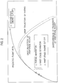
- a solid line in an explanatory view in FIG. 2 is the predicted flight path of the two-staged rocket 1, which is predicted by the mounted computer 13c.
- a segment from a launching point in which both of a ground surface distance and an altitude are "0" to a combustion cut-off point of the first-stage rocket engine 11b, which is indicated by a left plot point between two asterisk plot points present in FIG. 2 is the first-stage predicted flight path.
- a segment from a separating/discarding point of the first-stage rocket engine 11b to a combustion cut-off point of the second-stage rocket engine 13b, which is indicated by a right plot point between the two asterisk plot points present in FIG. 2 is the second-stage predicted flight path.
- the mounted computer 13c predicts a point where the first-stage rocket body 11 is predicted to impact, that is, a predicted impact point (IIP: Instantaneous Impact Point) in a case where the first-stage rocket engine 11b is cut-off at the cut-off point on the first-stage predicted flight path, and the first-stage rocket 11 is separated and discarded from the second-stage rocket 13 at the separating/discarding point placed forward thereof.
- a predicted impact point IIP: Instantaneous Impact Point
- the mounted computer 13c predicts respective points on which pieces of the fairing 15 are predicted to impact, that is, predicted impact points in a case where the two-staged rocket 1, which passes a certain time or is propelled by a certain distance since the first-stage rocket 11 is separated and discarded, opens the fairing 15 to halves and separates and discards the fairing 15 from the second-stage rocket 13 at a separating/discarding point indicated by a blank triangle plot point in FIG. 2 on the second-stage predicted flight path.
- the mounted computer 13c individually predicts the predicted impact points of the first-stage rocket 11 and the fairing 15 based on the flight speeds, flight positions and flight attitudes of the two-staged rocket 1 on the respective first-stage and second-stage predicted flight paths.
- the predicted impact point of the first-stage rocket body 11 is varied depending on to which point on the first-stage predicted flight path the cut-off point of the first-stage rocket engine 11b is to be decided. Accordingly, the mounted computer 13c sets a plurality of scheduled passing points on the first-stage predicted flight path, and individually predicts the predicted impact points of the first-stage rocket body 11 for cases where the respective scheduled passing points are decided to be the combustion cut-off point of the first-stage rocket engine 11b.
- the second-stage predicted flight path of the two-staged rocket 1 is varied depending on where the cut-off point of the first-stage rocket engine 11b on the first-stage predicted flight path is to be decided. Accordingly, after deciding the cut-off point of the first-stage rocket engine 11b, the mounted computer 13c predicts the second-stage predicted flight path of the two-staged rocket 1, which corresponds to the decided cut-off point.
- the mounted computer 13c predicts a predicted impact point of the fairing 15 while taking, as the separating/discarding point, a position of the two-staged rocket 1 on the second-stage predicted flight path when the two-staged rocket 1 flies for a certain time or by a certain distance from the separating/discarding point of the first-stage rocket 11.
- the separating/discarding point of the fairing 15 on the second-stage predicted flight path is assumed so as to individually correspond to each of the scheduled passing points on the first-stage predicted flight path, which is assumed as the cut-off point of the first-stage rocket engine 11b.
- the mounted computer 13c predicts the predicted impact point, which corresponds to the separating/discarding point of the fairing 15, individually in response to the respective scheduled passing points on the first-stage predicted flight path assumed as the cut-off point of the first-stage rocket engine 11b.
- the first-stage and second-stage predicted flight paths of the two-staged rocket 1, which are predicted by the mounted computer 13c, are so-called nominal flight paths.
- dispersion with respect to the nominal flight paths occurs by an influence of a weather condition or the like. Then, this dispersion is not reflected on the first-stage and second-stage predicted flight paths of the two-staged rocket 1, which serve as bases in an event where the mounted computer 13c predicts the predicted impact points of the first-stage rocket body 11 and the fairing 15.
- the mounted computer 13c predicts the predicted impact points of the first-stage rocket body 11 and the fairing 15 as ranges including some dispersion.
- topographic data that defines a safe area where the impact of the discarded object of the two-staged rocket 1 is allowed is stored together with data of the nominal flight path of the two-staged rocket 1.
- this topographic data is topographic data of down ranges (areas on a range) including impact limit lines (ILL) indicating boundary lines of lands to be protected from the impact of the discarded object and seas adjacent thereto.
- ILL impact limit lines
- data is stored, which indicates an area on which there drop fragments of the first-stage rocket body 11 and the fairing 15 separated and discarded from the second-stage rocket 13.
- a size and shape of such a fragment impact area differ depending on a launch capability of the two-staged rocket 1, that is, a launching enabled weight of the payload (not shown).
- a fragment impact area of the first-stage rocket 11 in a two-staged rocket 1 with a launching capability of 1.5 t (ton), which flies on a predicted flight path shown by a dotted line in FIG. 3 becomes such a range as shown by a dotted oval.
- a fragment drop area of the first-stage rocket 11 in a two-staged rocket 1 with a launch capability of 2 t (ton), which flies on a predicted flight path shown by an alternate long and short dash line in FIG. 3 becomes a smaller range than the fragment impact area of the first-stage rocket 11 in the two-staged rocket 1 with a launch capability of 1.5 t (ton).
- a blank rhombus in FIG. 3 which is plotted on the predicted flight path of the two-staged rocket 1 with a launching capability of 1.5 t (ton), is a predicted impact point (IIP) of the first-stage rocket 11 in the two-staged rocket 1 with a launch capability of 1.5 t (ton).
- a solid rhombus in FIG. 3 which is plotted on the predicted flight path of the two-staged rocket 1 with a launch capability of 2 t (ton), is an impact point (IIP) of the first-stage rocket 11 in the two-staged rocket 1 with a launch capability of 2 t (ton).
- the predicted impact point of the first-stage rocket 11 in the two-staged rocket 1 with a launching capability of 2 t (ton) is placed closer to the front in the flying direction of the two-staged rocket 1 with respect to the fragment drop area.
- the mounted computer 13c collates the predicted impact points of the first-stage rocket 11 and the fairing 15 (which include the fragment drop area) with the topographic data, and extracts a set in which both of the predicted impact point of the first-stage rocket 11 and the predicted impact point of the fairing 15 are located within the safe area SA. Moreover, the mounted computer 13c defines a scheduled passing point, which corresponds to the extracted set and is assumed to be the separating/discarding point of the first-stage rocket 11 on the first-stage predicted flight path, as an official separating/discarding point of the first-stage rocket 11.
- the mounted computer 13c defines a scheduled passing point, which is farthest from a launching spot of the two-staged rocket 1 among a plurality of scheduled passing points corresponding to the combinations, as the cut-off point of the first-stage rocket engine 11b.
- the two-staged rocket 1 will fly much farther by the propelling power of the first-stage rocket engine 11b. Therefore, the launch capability of the two-staged rocket 1 can be enhanced.
- the mounted computer 13c periodically and repeatedly predicts the predicted flight path of the two-staged rocket 1 and the predicted impact points of the first-stage rocket body 11 and the fairing 15, the predicted flight path and the predicted impact points being shown in FIG. 2 .
- the predicted flight path and the predicted impact point which are predicted by the mounted computer 13c, can be updated in response to such a fluctuation at any time.
- the mounted computer 13c cuts-off the first-stage rocket engine 11b, and thereafter, separates the first-stage rocket body 11 from the second-stage rocket 13.
- the mounted computer 13c separates the fairing 15 from the second-stage rocket 13.
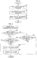
- the mounted computer 13c of this embodiment executes flight path prediction processing (Step S1), impact point prediction processing (Step S3), and engine cut-off determination processing (Step S5), which are shown in FIG. 4 , periodically and repeatedly during the flight of the two-staged rocket 1.
- the mounted computer 13c predicts the first-stage predicted flight path of the two-staged rocket 1 before separating and discarding the first-stage rocket body 11 and the second-stage predicted flight path of the two-staged rocket 1 after separating and discarding the first-stage rocket body 11.
- the mounted computer 13c predicts the first-stage predicted flight path based on the amount of the fuel remaining in the first-stage fuel tank 11a and based on the flight speed, the flight position and the flight attitude before the first-stage rocket engine 11b of the two-staged rocket 1 is cut-off, the flight speed, the flight position and the flight attitude being sensed by the IMU 13d.
- the mounted computer 13c predicts the second-stage predicted flight path based on the separating/discarding point of the first-stage rocket body 11, based on the amount of the fuel remaining in the second-stage fuel tank 13 a, and based on the flight speed, the flight position and the flight attitude after the first-stage rocket engine 11b of the two-staged rocket 1 is cut-off, the flight speed, the flight position and the flight attitude being sensed by the IMU 13d.
- the mounted computer 13c predicts the impact points (predicted impact points) of the first-stage rocket body 11 and the fairing 15.
- the mounted computer 13c predicts the impact points (predicted impact points) of the first-stage rocket body 11 and the fairing 15 based on the cut-off point of the first-stage rocket engine 11b, which is assumed on the predicted flight path of the first-stage rocket 11.
- Step S5 the mounted computer 13c confirms whether there is a set, in which both of the impact points (predicted impact points) of the first-stage rocket body 11 and the fairing 15 are located within the safe area SA, among the sets of the impact points of the first-stage rocket 11 and the fairing 15, which are predicted in the impact point prediction processing of Step S3 in the present cycle (Step S51).
- the mounted computer 13c determines whether the two-staged rocket 1 has reached the cut-off point, which is farthest from the launching spot of the two-staged rocket 1 among the cut-off points of the first-stage rocket engine 11b, which correspond to the predicted impact points of the first-stage rocket body 11 and the fairing 15, the predicted impact points being predicted in Step S3 of FIG. 4 in the present cycle (Step S52).
- the mounted computer 13c determines whether the two-staged rocket 1 has reached the engine cut-off point, which is farthest from the launching spot of the two-staged rocket 1 among the cut-off points of the first-stage rocket engine 11b, which correspond to the predicted impact points of the first-stage rocket body 11 and the fairing 15, the predicted impact points being predicted in Step S3 of FIG. 4 in the previous cycle (Step S53).
- Step S54 cuts-off of the first-stage rocket engine 11b (Step S54), and separates and discards the first-stage rocket body 11 and the fairing 15 from the second-stage rocket 13 at the respective separating/discarding points individually corresponding to the cut-off point (Step S55), and ends the separation determination processing.
- Step S1 in the flowchart of FIG. 4 is processing corresponding to a flight path prediction-processor in the claims.
- Step S3 in FIG. 4 is processing corresponding to an impact point prediction processor in the claims.
- Step S5 in FIG. 4 is processing corresponding to an engine cut-off controller in the claims.
- the flight path of the two-staged rocket 1 is periodically predicted during the flight, and the predicted impact points of the first-stage rocket body 11 and the fairing 15, which are separated and discarded from the second-stage rocket 13, in the case where the first-stage rocket engine 11 is cut-off at each scheduled passing point on the predicted flight path are predicted periodically.
- the processing for defining the farthest scheduled passing point from the launching spot of the two-staged rocket 1 as the combustion cut-off point of the first-stage rocket engine 11b is periodically performed.
- the cut-off point of the first-stage rocket engine 11b is updated to the farthest scheduled passing point from the launching spot of the two-staged rocket 1 at any time.
- the separating/discarding points of the first-stage rocket body 11 and the fairing 15 are also updated to the farthest points from the launching spot of the two-staged rocket 1 at any time.
- the first-stage rocket body 11 and the fairing 15, which are separated and discarded from the second-stage rocket 13 can be dropped to impact within the safe area SA.
- the mounted computer 13c periodically predicts the flight path of the two-staged rocket 1 during the flight, and periodically predicts the predicted impact points in the case where the first-stage rocket body 11 and the fairing 15 are separated and discarded from the second-stage rocket 13 at the respective scheduled passing points on the predicted flight path.
- the mounted computer 13c estimates whether none of the predicted impact points of the first-stage rocket 11 and the fairing 15, which are predicted in a next period, comes to be located within the safe area SA of the topographic data.
- the mounted computer 13c performs this estimation based on a change of at least one of the predicted flight path of the two-staged rocket 1 and the predicted impact points of the first-stage rocket 11 and the fairing 15, the change being observed between two immediately previous cycles which continue with each other.
- the mounted computer 13c adds variations obtained from the predicted impact points of the first-stage rocket body 11 and the fairing 15, which are predicted in the previous cycle, to the predicted impact points of the first-stage rocket body 11 and the fairing 15, which are predicted in the present cycle, and thereby estimates the predicted impact points of the first-stage rocket body 11 and the fairing 15, which are predicted in the nest cycle.
- the mounted computer 13c determines whether or not both of the predicted impact points of the first-stage rocket body 11 and the fairing 15 in the next cycle, the predicted impact points being thus estimated, are located within the safe area SA.
- the mounted computer 13c adds a variation obtained from the cut-off point of the first-stage rocket engine 11b, which is predicted in the previous cycle, to the cut-off point of the first-stage rocket engine 11b, which is predicted in the present cycle, and thereby estimates the cut-off point of the first-stage rocket engine 11b, which is predicted in the next cycle.
- the mounted computer 13c individually calculates the separating/discarding point of the first-stage rocket body 11 and the separating/discarding point of the fairing 15. Moreover, the mounted computer 13c determines whether both of the predicted impact point of the first-stage rocket 11 and the predicted impact point of the fairing 15 in the case where the first-stage rocket 11 and the fairing 15 are individually separated and discarded from each separating/discarding point are located within the safe area SA.
- both of the predicted impact points of the first-stage rocket body 11 and the fairing 15 are located within the safe area SA, then there is obtained such an estimation result that the predicted impact points of the first-stage rocket body 11 and the fairing 15, which are predicted in the next cycle, are located within the safe area SA of the topographical data. Meanwhile, if both of the predicted impact points of the first-stage rocket body 11 and the fairing 15 are not located within the safe area SA, then there is obtained such an estimation result that the predicted impact points of the first-stage rocket 11 and the fairing 15, which are predicted in the next cycle, come not to be located within the safe area SA of the topographical data.
- the mounted computer 13c decides the cut-off point of the first-stage rocket engine 11b.
- the mounted computer 13c extracts the sets of the combinations, in each of which both of the predicted impact point of the first-stage rocket body 11 and the predicted impact point of the fairing 15 are located within the safe area SA, among the sets of the predicted impact points of the first-stage rocket body 11 and the fairing 15, which are predicted in the present cycle. Then, the mounted computer 13c defines the farthest scheduled passing point from the launching spot of the two-staged rocket 1 among the scheduled passing points corresponding to the extracted sets as the cut-off point of the first-stage rocket engine 11b.
- the mounted computer 13c cuts-off the first-stage rocket engine 11b. Then, the mounted computer 13c separates the first-stage rocket 11 from the second-stage rocket 13 at the separation/discarding point corresponding to the engine cut-off point.
- the mounted computer 13c separates the fairing 15 from the second-stage rocket 13.
- the mounted computer 13c of this embodiment performs the flight path prediction processing (Step S1), the impact point prediction processing (Step S3), and the engine cut-off determination processing (Step S5), which are shown in FIG. 4 , periodically and repeatedly during the flight of the two-staged rocket 1.
- the mounted computer 13c performs similar processing to that of the first embodiment. Meanwhile, in the engine cut-off determination processing of Step S5, the mounted computer 13c performs different processing from that of the first embodiment.
- the mounted computer 13c estimates the predicted impact points of the first-stage rocket body 11 and the fairing 15, which are predicted in the next cycle (Step S56), and confirms whether there is a set in which both of the predicted impact points of the first-stage rocket body 11 and the fairing 15, which are thus estimated, are located within the safe area SA of the topographical data.
- the mounted computer 13c ends the engine cut-off determination processing.
- the mounted computer 13c determines whether or not the two-staged rocket 1 has reached the engine cut-off point, which is farthest from the launching spot of the two-staged rocket 1 among the combustion cut-off points of the first-stage rocket engine 11b, which correspond to the predicted impact points of the first-stage rocket body 11, the predicted impact points being predicted in Step S3 of FIG. 4 in the present cycle (Step S58).
- the mounted computer 13c cuts-off the first-stage rocket engine 11b (Step S59), separates and discards the first-stage rocket body 11 and the fairing 15 from the second-stage rocket 13 at the respective separating/discarding points individually corresponding to the cut-off point (Step S60), and ends the engine cut-off determination processing.
- Step S1 in the flowchart of FIG. 4 is the processing corresponding to the flight path prediction processor in the claims.
- Step S3 in FIG. 4 is the processing corresponding to the impact point prediction processor in the claims.
- Step S5 in FIG. 4 is the processing corresponding to the engine cut-off controller in the claims.
- the flight path of the two-staged rocket 1 is periodically predicted calculated during the flight, and the sets of the predicted impact points of the first-stage rocket body 11 and the fairing 15, which are separated and discarded from the second-stage rocket 13, in the case where the combustion of the first-stage rocket engine 11b is cut-off at each scheduled passing point on the predicted flight path are predicted periodically.
- the predicted impact points of the first-stage rocket body 11 and the fairing 15, which are predicted in the next cycle are individually estimated.
- the combustion cut-off point of the first-stage rocket engine 11b is updated to the farthest scheduled passing point from the launching spot of the two-staged rocket 1 at any time.
- the separating/discarding points of the first-stage rocket body 11 and the fairing 15 are also updated to the farthest points from the launching spot of the two-staged rocket 1 at any time.
- the first-stage rocket body 11 and the fairing 15, which are separated and discarded from the second-stage rocket 13 can be dropped to impact within the safe area SA.
- the first-stage rocket 11 and the fairing 15 correspond to a discarded object in the claims.
- the present disclosure is not limited to the above-mentioned respective embodiments, and is also applicable to an event of separating and discarding the fairing from the rocket no matter whether the rocket may be a single-staged one or a multi-staged one, and to a case of separating and discarding an n-th-stage rocket from an (n-1)-th-stage rocket in the multi-staged rocket.
- the fairing corresponds to the discarded object in the claims
- the (n-1)-th-stage rocket corresponds to the discarded object in the claims.
- the present disclosure can also be embodied in a form in which both of the fairing and the (n-1)-th-stage rocket body correspond to the discarded object in the claims.
- the present disclosure is also applicable to a single-staged rocket that does not include the fairing and drops as a discarded object by the cut-off of the engine.
- a description is made below of embodiments of such a case of applying the present disclosure to the rocket as described above.
- FIG. 7 is a partially cutaway front view showing a schematic configuration of a single-staged rocket on which control devices according to a third embodiment and fourth embodiment of the present disclosure are mounted.
- a single-staged rocket 3 of this embodiment which is shown in FIG. 7 , includes tanks 31a of liquid oxygen and liquid hydrogen and a rocket engine 31b that uses the liquid oxygen and the liquid hydrogen as propellants. Note that illustration of a solid rocket booster and an auxiliary engine, which are for use at a time of launching the single-staged rocket 3, is omitted.
- the single-staged rocket 3 drops and is discarded before long. Ignition and cut-off of the rocket engine 31b are controlled by a mounted computer (GCC: guidance control computer) 33c (corresponding to a control device for a rocket in the claims) of the single-staged rocket 3.
- GCC guidance control computer
- an IMU 33d is connected to the mounted computer 33c, which senses a flight speed, flight position and flight attitude of the single-staged rocket 3 by using gyro and acceleration sensors.
- the mounted computer 33c controls a propelling direction and the like of the rocket engine 31b based on the flight speed, the flight position and the flight attitude, which are sensed by the IMU 33d, so that the single-staged rocket 3 can fly through a nominal flight path of which data is stored in an internal memory of the mounted computer 33c.
- the mounted computer 33c monitors an amount of the propellants remaining in the tanks 31a of the single-staged rocket 3, and predicts a flight path of the single-staged rocket 3 based on the monitored amount of propellants and on the flight speed, flight position and flight attitude of the single-staged rocket 3, which are sensed by the IMU 33d.
- the flight path predicted by the mounted computer 33c (that is, a predicted flight path) includes a path along which the single-staged rocket 3 flies from now on by propelling power of the rocket engine 31b by using residual propellants of the-tanks 31a until the rocket engine 31b is cut-off.
- a segment from a launching point in which both of a ground surface distance and an altitude are "0" to a combustion cut-off point of the rocket engine 33b, which is indicated by a plot point as an asterisk in FIG. 8 is the predicted flight path of the single-staged rocket 3, which is predicted by the mounted computer 33c.
- the mounted computer 33c predicts a point where the single-staged rocket 3 is predicted to drop in a case where the rocket engine 31b of the single-staged rocket 3 is cut-off at an engine cut-off point on the predicted flight path, that is, predicts a predicted impact point (IIP). Note that the mounted computer 33c predicts the predicted impact point of the single-staged rocket 3 based on the flight speed, flight position and flight attitude of the single-staged rocket 3 on the predicted flight path.
- IIP predicted impact point
- the predicted impact point of the single-staged rocket 3 is varied depending on to which point on the predicted flight path the cut-off point of the first-stage rocket engine 31b is to be decided. Accordingly, the mounted computer 33c sets a plurality of scheduled passing points on the predicted flight path, and individually predicts the predicted impact points of the single-staged rocket 3 for cases where the respective scheduled passing points are decided to be the cut-off point of the rocket engine 31b.
- the predicted flight paths of the single-staged rocket 3, which is predicted by the mounted computer 33c, is a so-called nominal flight path.
- dispersion for the nominal flight path occurs by an influence of a weather condition or the like. Then, this dispersion is not reflected on the predicted flight path of the single-staged rocket 3, which serves as a base in an event where the mounted computer 33c predicts the predicted impact points of the single-staged rocket 3.
- the mounted computer 33c predicts the predicted impact point of the single-stage rocket 3 as a range including some error.
- topographic data that defines a safe area where the drop of the single-staged rocket 3 is allowed is stored together with data of the nominal flight path of the single-staged rocket 3.
- the stored topographical data is substantially like that shown in the explanatory view of FIG. 3 .
- the mounted computer 33c collates such predicted impact points of the single-staged rocket 3 (which include the fragment impact area) with the topographic data, and extracts the predicted impact point of the single-staged rocket 3, which is located within the safe area SA. Moreover, the mounted computer 33c defines a scheduled passing point, which corresponds to the extracted predicted impact point and is assumed to be the cut-off point of the rocket engine 31b on the predicted flight path of the single-staged rocket 3, as an official cut-off point of the rocket engine 31b.
- the mounted computer 33c defines a scheduled passing point, which is farthest from the launching spot of the single-staged rocket 3 among a plurality of such scheduled passing points, as the official cut-off point of the rocket engine 31b.
- the single-stage rocket 3 will fly much farther by the propelling power of the rocket engine 31b. Therefore, the launch capability of the single-staged rocket 3 can be enhanced.
- the mounted computer 33c periodically and repeatedly predicts the predicted flight path and predicted impact point of the single-staged rocket 3 the predicted flight path and the predicted impact point being shown in FIG. 8 .
- the predicted flight path and the predicted impact point which are predicted by the mounted computer 33c, can be updated in response to such a fluctuation at any time.
- the mounted computer 33c cuts-off the rocket engine 31b.
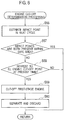
- the mounted computer 33c of this embodiment performs flight path prediction processing (Step S11), impact point prediction processing (Step S13), and engine cut-off determination processing (Step S15), which are shown in FIG. 9 , periodically and repeatedly during the flight of the single-staged rocket 3.
- the mounted computer 33c predicts the predicted flight path of the single-staged rocket 3 before the rocket engine 31b is cut-off.
- the mounted computer 33c predicts the predicted flight path of the single-staged rocket 3 based on the amount of the propellants remaining in the tanks 31a and based on the flight speed, flight position and flight attitude of the single-staged rocket 3 before the rocket engine 31b is cut-off, the flight speed, the flight position and the flight attitude being sensed by the IMU 33d.
- the mounted computer 33c predicts the impact point (predicted impact point) of the single-staged rocket 3.
- the mounted computer 33c predicts the impact point (predicted impact point) of the single-staged rocket 3 based on the cut-off point of the rocket engine 31b, which is assumed on the predicted flight path of the single-stage rocket 3.
- Step S15 the mounted computer 33c confirms whether there is an impact point, which is located within the safe area SA, among such impact points (predicted impact points) of the single-staged rocket 3, which are predicted in the impact point prediction processing of Step S 13 in the present cycle (Step S 151).
- the mounted computer 33c determines whether or not the single-stage rocket 3 has reached the engine cut-off point, which is farthest from the launching spot of the single-staged rocket 3 among the cut-off points of the rocket engine 31b, which correspond to the predicted drop point of the single-staged rocket 3, the predicted drop points being predicted in Step S13 of FIG. 9 in the present cycle (Step S 152).
- the mounted computer 33c determines whether or not the single-staged rocket 3 has reached the cut-off point, which is farthest from the launching spot of the single-staged rocket 3 among the cut-off points of the rocket engine 31b, which correspond to the predicted drop point of the single-staged rocket 3, the predicted drop points being predicted in Step S13 of FIG. 9 in the previous cycle (Step S153).
- Step S154 the mounted computer 33c cuts-off the rocket engine 31b (Step S154), and ends the engine cut-off processing.
- Step S11 in the flowchart of FIG. 9 is such processing corresponding to the flight path prediction processor in the claims.
- Step S13 in FIG. 9 is processing corresponding to the impact point prediction processor in the claims.
- Step S 15 in FIG. 9 is processing corresponding to the engine cut-off controller in the claims.
- the flight path of the single-staged rocket 3 is periodically predicted during the flight, and the predicted impact point of the single-staged rocket 3 in the case where the rocket engine 31b is cut-off at each scheduled passing point on the predicted flight path is predicted periodically.
- the processing for defining the farthest scheduled passing point from the launching spot of the single-staged rocket 3 as the combustion cut-off point of the rocket engine 31b is periodically performed.
- the engine cut-off point of the rocket engine 31b is updated to the farthest scheduled passing point from the launching spot of the single-staged rocket 3 at any time.
- the single-staged rocket 3 can be dropped to impact within the safe area SA.
- the mounted computer 33c predicts the flight path of the single-staged rocket 3 periodically during the flight, and periodically predicts the predicted impact point of the single-staged rocket 3 in the case where the rocket engine 31b is cut-off at each scheduled passing point on the predicted flight path.
- the mounted computer 33c estimates whether or not none of such predicted impact points of the single-staged rocket 3, which are predicted in a next period, comes to be located within the safe area SA of the topographic data.
- the mounted computer 33c performs this estimation based on a change of at least one of the predicted flight path of the single-staged rocket 3 and the predicted impact point of the single-staged rocket 3, the change being observed between two immediately previous cycles which continue with each other.
- the mounted computer 33c adds a variation obtained from the predicted impact point of the single-staged rocket 3, which is predicted in the previous cycle, to the predicted impact point of the single-staged rocket 3, which is predicted in the present cycle, and thereby estimates the predicted impact point of the single-staged rocket 3, which is predicted in the nest cycle. Then, the mounted computer 33c determines whether the predicted impact point of the single-staged rocket 3 in the next cycle, the predicted impact point being thus estimated, is located within the safe area SA.
- the mounted computer 33c adds a variation obtained from the cut-off point of the rocket engine 31b, which is predicted in the previous cycle, to the cut-off point of the rocket engine 31b, which is predicted in the present cycle, and thereby estimates the cut-off point of the rocket engine 31b, which is predicted in the next cycle.
- the mounted computer 33c determines whether the predicted impact point of the single-staged rocket 3 in the next cycle, the predicted impact point being thus estimated, is located within the safe area SA.
- the predicted impact point of the single-staged rocket 3 is located within the safe area SA, then there is obtained such an estimation result that the predicted impact point of the single-staged rocket 3, which is predicted in the next cycle, is located within the safe area SA of the topographical data. Meanwhile, if the predicted impact point of the single-staged rocket 3 is not located within the safe area SA, then there is obtained such an estimation result that the predicted impact point of the single-staged rocket 3, which is predicted in the next cycle, comes not to be located within the safe area SA of the topographical data.
- the mounted computer 33c decides the cut-off point of the rocket engine 31b.
- the mounted computer 33c extracts the predicted impact point of the single-staged rocket 3, which is located within the safe area SA, among such predicted impact points of the single-staged rocket 3, which are predicted in the present cycle. Then, the mounted computer 33c defines the farthest scheduled passing point from the launching spot of the single-staged rocket 3 among the scheduled passing points corresponding to the predicted impact point, which is thus extracted, as the cut-off point of the rocket engine 31b.
- the mounted computer 33c cuts-off the rocket engine 31b.
- the mounted computer 33c performs the flight path prediction processing (Step S11), the impact point prediction processing (Step S13), and the engine cut-off determination processing (Step S15), which are shown in FIG. 9 , periodically and repeatedly during the flight of the single-staged rocket 3.
- the mounted computer 33c performs similar processing to that of the third embodiment. Meanwhile, in the engine cut-off determination processing of Step S15, the mounted computer 33c performs different processing from that of the third embodiment.
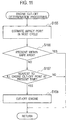
- the mounted computer 33c estimates the predicted impact points of the single-staged rocket 3, which are predicted in the next cycle (Step S155), and confirms whether there is a predicted impact point of the single-staged rocket 3, which is located within the safe area SA of the topographical data, among the predicted impact points of the single-staged rocket 3, which are thus estimated (Step S156).
- the mounted computer 33c ends the engine cut-off determination processing. In a case where there is no predicted impact point located within the safe area SA of the topographic data (NO in Step S156), the mounted computer 33c determines whether or not the single-staged rocket 3 has reaches the farthest combustion cut-off point the single-stages rocket 3 among the cut-off points of the rocket engine 31b, which correspond to the predicted impact points of the single-staged rocket 3, the predicted impact points being predicted in Step S13 of FIG. 9 in the present cycle (Step S157).
- Step S158 the mounted computer 33c cuts-off the rocket engine 31b (Step S158), and ends the engine cut-off determination processing.
- Step S11 in the flowchart of FIG. 9 is such processing corresponding to the flight path prediction processor in the claims.
- Step S13 in FIG. 9 is processing corresponding to the impact point prediction processor in the claims.
- Step S15 in FIG. 9 is processing corresponding to the engine cut-off controller in the claims.
- the flight path of the single-staged rocket 3 is periodically predicted during the flight, and the predicted impact point of the single-staged rocket 3 in the case where the rocket engine 31b is cut-off at each scheduled passing point on the predicted flight path is predicted periodically.
- the predicted impact points of the single-staged rocket 3, which are predicted in the next cycle are individually estimated.
- the cut-off point of the rocket engine 31b is not decided, but the processing for predicting the predicted flight path and the predicted impact point is also performed in the next cycle.
- the cut-off point of the rocket engine 31b is updated to the farthest scheduled passing point from the launching spot of the single-staged rocket 3 at any time.
- the single-staged rocket 3 can be dropped to impact within the safe area SA.
Landscapes
- Engineering & Computer Science (AREA)
- Remote Sensing (AREA)
- Aviation & Aerospace Engineering (AREA)
- Chemical & Material Sciences (AREA)
- Combustion & Propulsion (AREA)
- Radar, Positioning & Navigation (AREA)
- Automation & Control Theory (AREA)
- Aiming, Guidance, Guns With A Light Source, Armor, Camouflage, And Targets (AREA)
- Control Of Position, Course, Altitude, Or Attitude Of Moving Bodies (AREA)
Abstract
Description
- The present disclosure relates to a control device for a rocket.
- For example, in a multi-staged rocket for use in launching a payload such as a satellite, an engine of an n-th-stage rocket is ignited following a cut-off of an (n-1)-th-stage rocket engine, and an (n-1)-th-stage rocket is separated and discarded from an n-th-stage rocket.
- The (n-1)-th-stage rocket, which is separated and discarded, may be dropped to impact within a safe area apart from the land on the earth or from the sea near the land. Accordingly, in an event of launching the multi-staged rocket, engines of a second-stage rocket and after may be ignited at appropriate timing, that is, to separate and discard a preceding rocket body at appropriate timing.
- As a technology related to this, there is a proposal for separating and discarding a discarded object from a flying object when a horizontal flying distance from a takeoff point of the flying object, which is calculated from an acceleration of the flying object, exceeds a distance of a known separation/discarding point from the takeoff point, the separation/discarding point being suitable for dropping the discarded object to impact within such a safe area (for example, Patent Document 1).
- Patent Document 1:
JP H06-344994 A - Incidentally, in consideration of weather condition difference and the like at a launching time, the fuel of a little more than a standard quantity by adding a margin thereto may be loaded on a rocket. Therefore, when the rocket is separated and discarded at such a predetermined point as in the conventional proposal, the rocket is sometimes separated and discarded in a state where fuel by the amount of margin remains therein.
- The rocket may load the fuel, of which amount is appropriate in response to a consumption of the fuel by the rocket engine, in terms of enhancing a launch capability of the rocket by extending the flying distance with respect to a loaded amount of the fuel. In other words, it is ideal that the fuel loaded in the rocket be consumed as completely as possible. From a viewpoint, in terms of enhancing the launch capability of the rocket, the rocket may not be separated or discarded at such a predetermined point as in the conventional proposal.
- Moreover, also in a single-staged rocket in which the n-th rocket is not separated and discarded, the rocket engine may be cut-off after the loaded fuel is consumed without waste and the rocket may be dropped to impact within a safe area in order to enhance the launch capability of the rocket.
- The present disclosure has been made in consideration of the above-described circumstances. It is an object of the present disclosure to provide a control device for a rocket, which can drop a discarded object such as the discarded n-th rocket body and the single-staged rocket, of which engine is already cut-off, to the safe area while enhancing the launching capability by consuming the loaded fuel as much as possible.
- In order to achieve the above-described object, a control device for a rocket according to the present disclosure, which is described in
claim 1, is a control device for a rocket, cutting-off a rocket engine during flight of the rocket and discarding a discarded object, the control device being characterized by including: a flight path predicting processor that periodically predicts a predicted flight path, the rocket therealong flies from now on by residual fuel, based on a flight speed, a flight position and flight attitude of the rocket; an impact point predicting processor that for periodically predicts estimated impact points of the discarded object in a case of cutting-off the rocket engine at respective scheduled passing points on the predicted flight path of the rocket; and an engine cut-off controller that cuts-off the rocket engine and discards the discarded object in a case where the flight position of the rocket coincides with a scheduled passing point farthest from a launching spot of the rocket, the scheduled passing point also being where the discarded object discarded at a scheduled passing point is expected to impact within a safe area on predetermined topographic data, the scheduled passing point being among respective scheduled passing points on a predicted flight path predicted in a past cycle. - Moreover, in order to achieve the above-described object, a control device for a rocket according to the present disclosure, which is described in claim 2, is a control device for a rocket, cutting-off a rocket engine during flight of the rocket and discarding a discarded object, the control device being characterized by including: a flight path predicting processor that periodically predicts a predicted flight path, the rocket flies therealong from now on by residual fuel, based on a flight speed, a flight position and flight attitude of the rocket; a impact point predicting processor that periodically predicts predicted impact points of the discarded object in a case of cutting-off the rocket engine at respective scheduled passing points on the predicted flight path of the rocket; and an engine cut-off controller, in a case where it is estimated that none of predicted impact points of the discarded object, predicted for respective scheduled passing points on a predicted flight path predicted in a next cycle from a change of at least one of the predicted flight path of the rocket and the predicted impact point of the discarded object between two immediately previous cycles continuing with each other, comes to be located within a safe area on predetermined topographic data, for cutting-off the rocket engine and discarding the discarded object at a farthest scheduled passing point from a launching spot of the rocket, the scheduled passing point being where a predicted impact point of the discarded object is located within the safe area on the topographic data, the scheduled passing point being among respective scheduled passing points on a predicted flight path predicted at a present time, and the predicted impact point being predicted to correspond to each of the scheduled passing points.
- In accordance with the control device for a rocket according to the present disclosure, which is described in
claim 1, the path (predicted flight path) the rocket is predicted to fly therealong by the residual fuel during the flight of the launched rocket is predicted. This predicted flight path is periodically predicted and updated to latest contents. Then, every time when the predicted flight path is predicted, the respective points (predicted impact points) on which the discarded object is predicted to impact in the case where the rocket engine is cut-off at a plurality of the respective scheduled passing points set on the predicted flight path are predicted. The predicted impact points are also periodically predicted and updated to latest contents. - Then, the rocket engine is cut-off and the discarded object is discarded when the flying rocket reaches the scheduled passing point farthest from the launching spot of the rocket, the scheduled passing point also being where the discarded object discarded at the scheduled passing point is predicted to impact within the safe area on the predetermined topographic data, the scheduled passing point being among the respective scheduled passing points on the predicted flight path of the rocket, which was predicted in the past cycle.
- Moreover, also in the control device for a rocket according to the present disclosure, which is described in claim 2, in a similar way to the control device for a rocket, which is described in
claim 1, the predicted flight path of the rocket and the predicted impact points of the discarded object in the case where the rocket engine is cut-off at the plurality of respective scheduled passing points set on the predicted flight path are periodically predicted during the flight of the launched rocket, and are updated to the latest contents. - Then, if the discarded object does not impact within the safe area of the topographic data when the rocket engine is cut-off and the discarded object is discarded at the respective passing points on the predicted flight path, which are predicted in the next cycle, then the rocket engine is cut-off and the discarded object is discarded when the flying rocket reaches the scheduled passing point farthest from the launching spot of the rocket, the scheduled passing point also being where it is predicted that then engine is cut-off and the discarded object discarded at the scheduled passing point impacts within the safe area on the predetermined topographic data, the scheduled passing point being among the respective scheduled passing points on the latest predicted flight path of the rocket, which is predicted at the present time.
- Here, as the discarded object of the rocket, for example, there are mentioned: a fairing separated and discarded in an event of putting a payload in a single-staged rocket or a multi-staged rocket; an (n-1)-th-stage rocket separated and discarded from an n-th-stage rocket in the multi-staged rocket; and further; the single-staged rocket itself.
- Therefore, in accordance with the control device for a rocket according to the present disclosure, which is described in
claim 1 or claim 2, for example, even if the fuel consumed by the rocket engine in order to fly the rocket along the determined flight path fluctuates due to a weather condition and the like, the rocket is flied to the farthest scheduled passing point at which the discarded object drops to impact within the safe area of the topographic data, and thereafter, the rocket engine is cut-off, and the discarded object is discarded. - Hence, while extending the flight distance of the rocket by consuming the loaded fuel as much as possible to thereby enhance the launch capability thereof, the discarded object can be dropped to impact within the safe area.
- Moreover, the control device for a rocket according to the present disclosure, which is described in
claim 3, is the control device for a rocket according to the present disclosure, which is described in either one ofclaims 1 and 2, characterized in that the rocket is a multi-staged rocket, the discarded object includes at least an (n-1)-th-stage rocket body separated and discarded from an n-th-stage rocket, the flight path predicting processor periodically predicts a predicted flight path, along which the multi-staged rocket flies from now on by propelling power generated by an (n-1)-th-stage rocket engine by using residual fuel, based on a flight speed, a flight position and flight attitude of the multi-staged rocket, and for respective scheduled passing points on the predicted flight path of the multi-staged rocket, the impact point predicting processor periodically predicts predicted impact points of the (n-1)-th-stage rocket in a case where the (n-1)-th-stage rocket engine is cut-off and the (n-1)-th-stage rocket body is separated and discarded from the n-th-stage rocket. - In accordance with the control device for a rocket according to the present disclosure, which is described in
claim 3, in accordance with the control device for rocket according to the present disclosure, which is described in either one ofclaims 1 and 2, in a case where the rocket is a multi-staged rocket, the separation/discarding of the (n-1)-th-stage rocket in which the rocket engine is cut-off from the n-th-stage rocket is performed at the scheduled passing point, which is farthest from a launching spot of the multi-staged rocket, and at which the separated and discarded (n-1)-th-stage rocket body drops to impact within the safe area. - Therefore, the flight distance of the multi-staged rocket by the propelling power of the (n-1)-th-stage rocket engine can be extended by consuming the fuel of the (n-1)-th-stage rocket as much as possible, and the (n-1)-th-stage rocket body separated and discarded from the n-th-stage rocket can be dropped to impact within the safe area.
- In accordance with the present disclosure, the discarded object such as the discarded n-th rocket body and the single-staged rocket of which engine is already cut-off can be dropped to impact within the safe area while enhancing the launch capability by consuming the loaded fuel as much as possible.
-
-
FIG. 1 is a partially cutaway front view showing a schematic configuration of a second-stage rocket on which a control device according to a first embodiment of the present disclosure is mounted. -
FIG. 2 is an explanatory view showing a nominal flight path of the two-staged rocket ofFIG. 1 and a drop trajectory of a separated/discarded object from the rocket. -
FIG. 3 is an explanatory view showing topographic data of down ranges (areas on range) including impact limit lines (ILLs) of countries, which are stored in an internal memory of a controller inFIG. 1 . -
FIG. 4 is a flowchart showing a procedure of processing performed by a mounted computer inFIG. 1 . -
FIG. 5 is a flowchart showing an example of a specific procedure of engine cut-off determination processing inFIG. 4 . -
FIG. 6 is a flowchart showing an example of a specific procedure of engine cut-off determination processing inFIG. 4 , which is performed by a mounted computer of a two-staged rocket on which a control device according to a second embodiment of the present disclosure is mounted. -
FIG. 7 is a partially cutaway front view showing a schematic configuration of a single-staged rocket on which control devices according to a third embodiment and fourth embodiment of the present disclosure are mounted. -
FIG. 8 is an explanatory view showing a nominal flight path of the single-staged rocket inFIG. 7 and a drop trajectory of the rocket body. -
FIG. 9 is a flowchart showing a procedure of processing performed by a mounted computer inFIG. 7 . -
FIG. 10 is a flowchart showing an example of a specific procedure of engine cut-off determination processing inFIG. 9 , which is performed by the mounted computer of the single-staged rocket on which the control device according to the third embodiment of the present disclosure is mounted. -
FIG. 11 is a flowchart showing an example of a specific procedure of engine cut-off determination processing inFIG. 9 , which is performed by the mounted computer of the single-staged rocket on which the control device according to the fourth embodiment of the present disclosure is mounted. - A description is made below of embodiments of a control device for a rocket according to the present disclosure while referring to the drawings. In the following embodiments, a description is made of a two-staged rocket as an example of the rocket.
-
FIG. 1 is a partially cutaway front view showing a schematic configuration of a two-staged rocket on which the control device according to a first embodiment is mounted. A two-stagedrocket 1 of this embodiment, which is shown inFIG. 1 , includes first-stage and second-stage rockets fairing 15. - The first-stage and second-
stage rockets fuel tanks rocket engines rocket 1, is omitted. - The second-
stage rocket 13 is connected to an upper portion of the first-stage rocket 11 through a separation mechanism (not shown). When the first-stage rocket engine 11b is cut-off by substantially finishing use of propellants (liquid oxygen and liquid hydrogen) of thefuel tank 11a, the first-stage rocket body 11 is separated from the second-stage rocket 13 by the separation mechanism, and the second-stage rocket engine 13b is ignited. - The
fairing 15 covers a payload (not shown) connected to an upper portion of the second-stage rocket 13 through a separation mechanism, and opens to halves from a tip end thereof during flight of the two-stagedrocket 1, and is separated and discarded from the two-stagedrocket 13. - In some case, the
fairing 15 is separated and discarded from the second-stage rocket 13 before the first-stage rocket body 11 is separated and discarded from the second-stage rocket 13. However, in this embodiment, a description is made of a case where thefairing 15 is separated and discarded from the second-stage rocket 13 after elapse of a certain time since the first-stage rocket body 11 is separated and discarded from the second-stage rocket 13 or after the first-stage rocket 11 is propelled by a certain distance since the first-stage rocket 11 is separated and discarded. - When the
fairing 15 is separated and discarded from the second-stage rocket 13, the payload (not shown) in an inside of thefairing 15 is exposed. When the second-stage rocket engine 13b is cut-off by finishing use of propellants (liquid oxygen and liquid hydrogen) of thefuel tank 11a, the payload is separated from the second-stage rocket 13, and is placed into a satellite orbit. - The ignition and cut-off of the first-stage and second-
stage rocket engines stage rocket body 11 and thefairing 15 from the second-stage rocket 13 are controlled by a mounted computer (GCC: Guidance Control Computer) 13c (corresponding to a control device for a rocket in claims) in the second-stage rocket 13. - To the mounted
computer 13c, an IMU (Inertial Measuring Unit) 13d is connected, which calculates a flight speed, flight position and flight attitude of the two-stagedrocket 1 by using gyro and acceleration sensors. The mountedcomputer 13c controls propelling directions and the like of therocket engines rocket 1 can fly through a nominal flight path of which data is stored in an internal memory of the mountedcomputer 13c. - Moreover, the mounted
computer 13c monitors amounts of the fuel remaining in thefuel tanks rocket 1, and predicts a flight path of the two-stagedrocket 1 based on the monitored amounts of fuel and on the flight speed, flight position and flight attitude of the two-stagedrocket 1, which are sensed by theIMU 13 d. - The flight path predicted by the mounted
computer 13c (that is, a predicted flight path) includes a path along which the two-stagedrocket 1 flies from now on by propelling power of the first-stage rocket engine 11b by using residual fuel of the first-stage rocket 11 until combustion of the first-stage rocket engine 11b is cut-off. Hereinafter, this predicted flight path is referred to as a first-stage predicted flight path. - Moreover, the predicted flight path includes a path along which the two-staged
rocket 1 flies by propelling power of the second-stage rocket engine 13b by using the fuel of the second-stage rocket 13 after the first-stage rocket 11 is separated and discarded from the second-stage rocket 13. Hereinafter, this predicted flight path is referred to as a second-stage predicted flight path. - Note that a solid line in an explanatory view in
FIG. 2 is the predicted flight path of the two-stagedrocket 1, which is predicted by the mountedcomputer 13c. In this solid line, a segment from a launching point in which both of a ground surface distance and an altitude are "0" to a combustion cut-off point of the first-stage rocket engine 11b, which is indicated by a left plot point between two asterisk plot points present inFIG. 2 , is the first-stage predicted flight path. Moreover, a segment from a separating/discarding point of the first-stage rocket engine 11b to a combustion cut-off point of the second-stage rocket engine 13b, which is indicated by a right plot point between the two asterisk plot points present inFIG. 2 , is the second-stage predicted flight path. - Furthermore, the mounted
computer 13c predicts a point where the first-stage rocket body 11 is predicted to impact, that is, a predicted impact point (IIP: Instantaneous Impact Point) in a case where the first-stage rocket engine 11b is cut-off at the cut-off point on the first-stage predicted flight path, and the first-stage rocket 11 is separated and discarded from the second-stage rocket 13 at the separating/discarding point placed forward thereof. - Moreover, the mounted
computer 13c predicts respective points on which pieces of the fairing 15 are predicted to impact, that is, predicted impact points in a case where the two-stagedrocket 1, which passes a certain time or is propelled by a certain distance since the first-stage rocket 11 is separated and discarded, opens the fairing 15 to halves and separates and discards the fairing 15 from the second-stage rocket 13 at a separating/discarding point indicated by a blank triangle plot point inFIG. 2 on the second-stage predicted flight path. - Note that the mounted
computer 13c individually predicts the predicted impact points of the first-stage rocket 11 and the fairing 15 based on the flight speeds, flight positions and flight attitudes of the two-stagedrocket 1 on the respective first-stage and second-stage predicted flight paths. - Moreover, the predicted impact point of the first-
stage rocket body 11 is varied depending on to which point on the first-stage predicted flight path the cut-off point of the first-stage rocket engine 11b is to be decided. Accordingly, the mountedcomputer 13c sets a plurality of scheduled passing points on the first-stage predicted flight path, and individually predicts the predicted impact points of the first-stage rocket body 11 for cases where the respective scheduled passing points are decided to be the combustion cut-off point of the first-stage rocket engine 11b. - Furthermore, the second-stage predicted flight path of the two-staged
rocket 1 is varied depending on where the cut-off point of the first-stage rocket engine 11b on the first-stage predicted flight path is to be decided. Accordingly, after deciding the cut-off point of the first-stage rocket engine 11b, the mountedcomputer 13c predicts the second-stage predicted flight path of the two-stagedrocket 1, which corresponds to the decided cut-off point. Then, the mountedcomputer 13c predicts a predicted impact point of the fairing 15 while taking, as the separating/discarding point, a position of the two-stagedrocket 1 on the second-stage predicted flight path when the two-stagedrocket 1 flies for a certain time or by a certain distance from the separating/discarding point of the first-stage rocket 11. - As described above, the separating/discarding point of the fairing 15 on the second-stage predicted flight path is assumed so as to individually correspond to each of the scheduled passing points on the first-stage predicted flight path, which is assumed as the cut-off point of the first-
stage rocket engine 11b. Hence, in the same way as the predicted impact point of the first-stage rocket 11, the mountedcomputer 13c predicts the predicted impact point, which corresponds to the separating/discarding point of the fairing 15, individually in response to the respective scheduled passing points on the first-stage predicted flight path assumed as the cut-off point of the first-stage rocket engine 11b. - Incidentally, the first-stage and second-stage predicted flight paths of the two-staged
rocket 1, which are predicted by the mountedcomputer 13c, are so-called nominal flight paths. However, in an actual flight path of the two-stagedrocket 1, dispersion with respect to the nominal flight paths occurs by an influence of a weather condition or the like. Then, this dispersion is not reflected on the first-stage and second-stage predicted flight paths of the two-stagedrocket 1, which serve as bases in an event where the mountedcomputer 13c predicts the predicted impact points of the first-stage rocket body 11 and thefairing 15. - Accordingly, in consideration of the dispersion of the actual flight path of the two-staged
rocket 1 with respect to the nominal flight path, the mountedcomputer 13c predicts the predicted impact points of the first-stage rocket body 11 and the fairing 15 as ranges including some dispersion. - Note that, in the internal memory of the mounted
computer 13c, topographic data that defines a safe area where the impact of the discarded object of the two-stagedrocket 1 is allowed is stored together with data of the nominal flight path of the two-stagedrocket 1. As shown in an explanatory view ofFIG. 3 , this topographic data is topographic data of down ranges (areas on a range) including impact limit lines (ILL) indicating boundary lines of lands to be protected from the impact of the discarded object and seas adjacent thereto. Hence, a residual area excluding areas on more land sides than the impact limit lines becomes a safe area SA where the impact of the discarded object of the two-stagedrocket 1 is allowed. - Moreover, in the internal memory of the mounted
computer 13c, data is stored, which indicates an area on which there drop fragments of the first-stage rocket body 11 and the fairing 15 separated and discarded from the second-stage rocket 13. A size and shape of such a fragment impact area differ depending on a launch capability of the two-stagedrocket 1, that is, a launching enabled weight of the payload (not shown). - This is because, as the two-staged
rocket 1 has a higher launch capability, inertia in a flying direction, which acts on the first-stage rocket body 11 at the separation/discarding time, is larger, and a dispersion degree of the fragments of the first-stage rocket body 11 after the separation/discarding, the dispersion being caused by force other than the inertia, is smaller. - For example, a fragment impact area of the first-
stage rocket 11 in a two-stagedrocket 1 with a launching capability of 1.5 t (ton), which flies on a predicted flight path shown by a dotted line inFIG. 3 , becomes such a range as shown by a dotted oval. Moreover, a fragment drop area of the first-stage rocket 11 in a two-stagedrocket 1 with a launch capability of 2 t (ton), which flies on a predicted flight path shown by an alternate long and short dash line inFIG. 3 , becomes a smaller range than the fragment impact area of the first-stage rocket 11 in the two-stagedrocket 1 with a launch capability of 1.5 t (ton). - Note that a blank rhombus in
FIG. 3 , which is plotted on the predicted flight path of the two-stagedrocket 1 with a launching capability of 1.5 t (ton), is a predicted impact point (IIP) of the first-stage rocket 11 in the two-stagedrocket 1 with a launch capability of 1.5 t (ton). Moreover, a solid rhombus inFIG. 3 , which is plotted on the predicted flight path of the two-stagedrocket 1 with a launch capability of 2 t (ton), is an impact point (IIP) of the first-stage rocket 11 in the two-stagedrocket 1 with a launch capability of 2 t (ton). - By an amount that the inertia in the flying direction, which acts on the first-
stage rocket 11 at the separation/discarding time, is larger in the two-stagedrocket 1 with a launching capability of 2 t (ton) than in the two-stagedrocket 1 with a launching capability of 1.5 t (ton), the predicted impact point of the first-stage rocket 11 in the two-stagedrocket 1 with a launching capability of 2 t (ton) is placed closer to the front in the flying direction of the two-stagedrocket 1 with respect to the fragment drop area. - Then, the mounted
computer 13c collates the predicted impact points of the first-stage rocket 11 and the fairing 15 (which include the fragment drop area) with the topographic data, and extracts a set in which both of the predicted impact point of the first-stage rocket 11 and the predicted impact point of the fairing 15 are located within the safe area SA. Moreover, the mountedcomputer 13c defines a scheduled passing point, which corresponds to the extracted set and is assumed to be the separating/discarding point of the first-stage rocket 11 on the first-stage predicted flight path, as an official separating/discarding point of the first-stage rocket 11. - At this time, in a case where there are plural sets of combinations in each of which both of the predicted impact point of the first-
stage rocket body 11 and the predicted impact point of the fairing 15, each including the fragment impact area, are located within the safe area SA, the mountedcomputer 13c defines a scheduled passing point, which is farthest from a launching spot of the two-stagedrocket 1 among a plurality of scheduled passing points corresponding to the combinations, as the cut-off point of the first-stage rocket engine 11b. - In such a way, until the combustion of the first-
stage rocket engine 11b is cut-off, the two-stagedrocket 1 will fly much farther by the propelling power of the first-stage rocket engine 11b. Therefore, the launch capability of the two-stagedrocket 1 can be enhanced. - Note that the mounted
computer 13c periodically and repeatedly predicts the predicted flight path of the two-stagedrocket 1 and the predicted impact points of the first-stage rocket body 11 and the fairing 15, the predicted flight path and the predicted impact points being shown inFIG. 2 . In such a way, even if a consumption pace of the fuel by the two-stagedrocket 1 fluctuates during the flight due to a change of the weather condition, and the like, the predicted flight path and the predicted impact point, which are predicted by the mountedcomputer 13c, can be updated in response to such a fluctuation at any time. - Then, when the two-staged
rocket 1 reaches the cut-off point of the first-stage rocket engine 11b (when the flight position of the two-stagedrocket 1 coincides therewith), the mountedcomputer 13c cuts-off the first-stage rocket engine 11b, and thereafter, separates the first-stage rocket body 11 from the second-stage rocket 13. - Moreover, when the two-staged
rocket 1 that has separated and discarded the first-stage rocket 11 therefrom reaches the separating/discarding point of the fairing 15 (with which the flight position of the two-stagedrocket 1 coincides), the mountedcomputer 13c separates the fairing 15 from the second-stage rocket 13. - Next, referring to a flowchart of
FIG. 4 , a description is made of processing regarding the combustion cut-off of the first-stage rocket engine 11b, which is performed by the above-mentionedmounted computer 13c during the flight of the two-stagedrocket 1. - In order to cut-off of the first-
stage rocket engine 11b so that the first-stage rocket body 11 and the fairing 15 can drop to impact within the safe area SA, the mountedcomputer 13c of this embodiment executes flight path prediction processing (Step S1), impact point prediction processing (Step S3), and engine cut-off determination processing (Step S5), which are shown inFIG. 4 , periodically and repeatedly during the flight of the two-stagedrocket 1. - Then, in the flight path prediction processing of Step S1, the mounted
computer 13c predicts the first-stage predicted flight path of the two-stagedrocket 1 before separating and discarding the first-stage rocket body 11 and the second-stage predicted flight path of the two-stagedrocket 1 after separating and discarding the first-stage rocket body 11. - Note that the mounted
computer 13c predicts the first-stage predicted flight path based on the amount of the fuel remaining in the first-stage fuel tank 11a and based on the flight speed, the flight position and the flight attitude before the first-stage rocket engine 11b of the two-stagedrocket 1 is cut-off, the flight speed, the flight position and the flight attitude being sensed by theIMU 13d. - Moreover, the mounted
computer 13c predicts the second-stage predicted flight path based on the separating/discarding point of the first-stage rocket body 11, based on the amount of the fuel remaining in the second-stage fuel tank 13 a, and based on the flight speed, the flight position and the flight attitude after the first-stage rocket engine 11b of the two-stagedrocket 1 is cut-off, the flight speed, the flight position and the flight attitude being sensed by theIMU 13d. - Next, in the impact point prediction processing of Step S3, the mounted
computer 13c predicts the impact points (predicted impact points) of the first-stage rocket body 11 and thefairing 15. Here, the mountedcomputer 13c predicts the impact points (predicted impact points) of the first-stage rocket body 11 and the fairing 15 based on the cut-off point of the first-stage rocket engine 11b, which is assumed on the predicted flight path of the first-stage rocket 11. - Subsequently, in the engine cut-off determination processing of Step S5, first, as shown in a flowchart of
FIG. 5 , the mountedcomputer 13c confirms whether there is a set, in which both of the impact points (predicted impact points) of the first-stage rocket body 11 and the fairing 15 are located within the safe area SA, among the sets of the impact points of the first-stage rocket 11 and the fairing 15, which are predicted in the impact point prediction processing of Step S3 in the present cycle (Step S51). - In a case where there is a set in which both of the drop points of the first-
stage rocket body 11 and the fairing 15 are located within the safe area SA (YES in Step S51), the mountedcomputer 13c determines whether the two-stagedrocket 1 has reached the cut-off point, which is farthest from the launching spot of the two-stagedrocket 1 among the cut-off points of the first-stage rocket engine 11b, which correspond to the predicted impact points of the first-stage rocket body 11 and the fairing 15, the predicted impact points being predicted in Step S3 ofFIG. 4 in the present cycle (Step S52). - In contrast, in a case where there is no set in which both of the drop impact points of the first-
stage rocket 11 and the fairing 15 are located within the safe area SA (NO in Step S51), the mountedcomputer 13c determines whether the two-stagedrocket 1 has reached the engine cut-off point, which is farthest from the launching spot of the two-stagedrocket 1 among the cut-off points of the first-stage rocket engine 11b, which correspond to the predicted impact points of the first-stage rocket body 11 and the fairing 15, the predicted impact points being predicted in Step S3 ofFIG. 4 in the previous cycle (Step S53). - Then, in the case of having determined that the two-staged
rocket 1 has reached the farthest combustion cut-off point from the launching spot of the two-staged rocket 1 (YES in Step S52 or Step S53), then the mountedcomputer 13c cuts-off of the first-stage rocket engine 11b (Step S54), and separates and discards the first-stage rocket body 11 and the fairing 15 from the second-stage rocket 13 at the respective separating/discarding points individually corresponding to the cut-off point (Step S55), and ends the separation determination processing. - As obvious also from the above description, in this embodiment, Step S1 in the flowchart of
FIG. 4 is processing corresponding to a flight path prediction-processor in the claims. Moreover, in this embodiment, Step S3 inFIG. 4 is processing corresponding to an impact point prediction processor in the claims. Furthermore, in this embodiment, Step S5 inFIG. 4 is processing corresponding to an engine cut-off controller in the claims. - As described above, in the two-staged
rocket 1 of this embodiment, the flight path of the two-stagedrocket 1 is periodically predicted during the flight, and the predicted impact points of the first-stage rocket body 11 and the fairing 15, which are separated and discarded from the second-stage rocket 13, in the case where the first-stage rocket engine 11 is cut-off at each scheduled passing point on the predicted flight path are predicted periodically. - Then, while the scheduled passing points in each of which both of the predicted impact points of the first-
stage rocket body 11 and the fairing 15 are located within the safe area SA are present, the processing for defining the farthest scheduled passing point from the launching spot of the two-stagedrocket 1 as the combustion cut-off point of the first-stage rocket engine 11b is periodically performed. - Therefore, the cut-off point of the first-
stage rocket engine 11b is updated to the farthest scheduled passing point from the launching spot of the two-stagedrocket 1 at any time. In such a way, the separating/discarding points of the first-stage rocket body 11 and the fairing 15 are also updated to the farthest points from the launching spot of the two-stagedrocket 1 at any time. - Hence, while extending the flight distance by consuming the fuel in the
fuel tanks stage rocket 11 and the second-stage rocket 13 as much as possible to thereby enhance the launch capability of the two-stagedrocket 1, the first-stage rocket body 11 and the fairing 15, which are separated and discarded from the second-stage rocket 13, can be dropped to impact within the safe area SA. - Next, a description is made of a control device according to a second embodiment of the present disclosure, which is mounted on the two-staged
rocket 1. - Also in this embodiment, the mounted
computer 13c periodically predicts the flight path of the two-stagedrocket 1 during the flight, and periodically predicts the predicted impact points in the case where the first-stage rocket body 11 and the fairing 15 are separated and discarded from the second-stage rocket 13 at the respective scheduled passing points on the predicted flight path. - Then, in this embodiment, the mounted
computer 13c estimates whether none of the predicted impact points of the first-stage rocket 11 and the fairing 15, which are predicted in a next period, comes to be located within the safe area SA of the topographic data. The mountedcomputer 13c performs this estimation based on a change of at least one of the predicted flight path of the two-stagedrocket 1 and the predicted impact points of the first-stage rocket 11 and the fairing 15, the change being observed between two immediately previous cycles which continue with each other. - Specifically, for example, the mounted
computer 13c adds variations obtained from the predicted impact points of the first-stage rocket body 11 and the fairing 15, which are predicted in the previous cycle, to the predicted impact points of the first-stage rocket body 11 and the fairing 15, which are predicted in the present cycle, and thereby estimates the predicted impact points of the first-stage rocket body 11 and the fairing 15, which are predicted in the nest cycle. - Then, the mounted
computer 13c determines whether or not both of the predicted impact points of the first-stage rocket body 11 and the fairing 15 in the next cycle, the predicted impact points being thus estimated, are located within the safe area SA. - Alternatively, for example, the mounted
computer 13c adds a variation obtained from the cut-off point of the first-stage rocket engine 11b, which is predicted in the previous cycle, to the cut-off point of the first-stage rocket engine 11b, which is predicted in the present cycle, and thereby estimates the cut-off point of the first-stage rocket engine 11b, which is predicted in the next cycle. - Then, from the estimated cut-off point of the first-
stage rocket engine 11b in the next cycle, the mountedcomputer 13c individually calculates the separating/discarding point of the first-stage rocket body 11 and the separating/discarding point of thefairing 15. Moreover, the mountedcomputer 13c determines whether both of the predicted impact point of the first-stage rocket 11 and the predicted impact point of the fairing 15 in the case where the first-stage rocket 11 and the fairing 15 are individually separated and discarded from each separating/discarding point are located within the safe area SA. - If both of the predicted impact points of the first-
stage rocket body 11 and the fairing 15 are located within the safe area SA, then there is obtained such an estimation result that the predicted impact points of the first-stage rocket body 11 and the fairing 15, which are predicted in the next cycle, are located within the safe area SA of the topographical data. Meanwhile, if both of the predicted impact points of the first-stage rocket body 11 and the fairing 15 are not located within the safe area SA, then there is obtained such an estimation result that the predicted impact points of the first-stage rocket 11 and the fairing 15, which are predicted in the next cycle, come not to be located within the safe area SA of the topographical data. - Then, in such a case of having estimated that none of the predicted impact points of the first-
stage rocket body 11 and the fairing 15, which are predicted in the next cycle, comes to be located within the safe area SA of the topographical data, the mountedcomputer 13c decides the cut-off point of the first-stage rocket engine 11b. - Specifically, the mounted
computer 13c extracts the sets of the combinations, in each of which both of the predicted impact point of the first-stage rocket body 11 and the predicted impact point of the fairing 15 are located within the safe area SA, among the sets of the predicted impact points of the first-stage rocket body 11 and the fairing 15, which are predicted in the present cycle. Then, the mountedcomputer 13c defines the farthest scheduled passing point from the launching spot of the two-stagedrocket 1 among the scheduled passing points corresponding to the extracted sets as the cut-off point of the first-stage rocket engine 11b. - Then, when the two-staged
rocket 1 reaches the cut-off point of the first-stage rocket engine 11b (when the flight position of the two-stagedrocket 1 coincides therewith), the mountedcomputer 13c cuts-off the first-stage rocket engine 11b. Then, the mountedcomputer 13c separates the first-stage rocket 11 from the second-stage rocket 13 at the separation/discarding point corresponding to the engine cut-off point. - Moreover, when the two-staged
rocket 1 that has separated and discarded the first-stage rocket body 11 therefrom reaches the separating/discarding point of the fairing 15 (with which the flight position of the two-stagedrocket 1 coincides), the separating/discarding point corresponding to the engine cut-off point, the mountedcomputer 13c separates the fairing 15 from the second-stage rocket 13. - Therefore, also in this embodiment, in order to separate and discard the first-
stage rocket body 11 and the fairing 15 so that the first-stage rocket 11 and the fairing 15 can drop to impact within the safe area SA, the mountedcomputer 13c of this embodiment performs the flight path prediction processing (Step S1), the impact point prediction processing (Step S3), and the engine cut-off determination processing (Step S5), which are shown inFIG. 4 , periodically and repeatedly during the flight of the two-stagedrocket 1. - Then, in the flight path prediction processing of Step S1 and the impact point prediction processing of Step S3, the mounted
computer 13c performs similar processing to that of the first embodiment. Meanwhile, in the engine cut-off determination processing of Step S5, the mountedcomputer 13c performs different processing from that of the first embodiment. - Specifically, first, as shown in a flowchart of
FIG. 6 , the mountedcomputer 13c estimates the predicted impact points of the first-stage rocket body 11 and the fairing 15, which are predicted in the next cycle (Step S56), and confirms whether there is a set in which both of the predicted impact points of the first-stage rocket body 11 and the fairing 15, which are thus estimated, are located within the safe area SA of the topographical data. - In a case where there is a set in which both of the predicted impact points of the first-
stage rocket body 11 and the fairing 15, which are thus estimated, are located within the safe area SA of the topographical data (YES in Step S57), the mountedcomputer 13c ends the engine cut-off determination processing. In a case where there is no set in which both of the predicted impact points of the first-stage rocket body 11 and the fairing 15, which are thus estimated, are located within the safe area SA of the topographical data (NO in Step S57), the mountedcomputer 13c determines whether or not the two-stagedrocket 1 has reached the engine cut-off point, which is farthest from the launching spot of the two-stagedrocket 1 among the combustion cut-off points of the first-stage rocket engine 11b, which correspond to the predicted impact points of the first-stage rocket body 11, the predicted impact points being predicted in Step S3 ofFIG. 4 in the present cycle (Step S58). - Then, in the case of having determined that the two-staged
rocket 1 has reached the farthest combustion cut-off point from the launching spot of the two-staged rocket 1 (YES in Step S58), the mountedcomputer 13c cuts-off the first-stage rocket engine 11b (Step S59), separates and discards the first-stage rocket body 11 and the fairing 15 from the second-stage rocket 13 at the respective separating/discarding points individually corresponding to the cut-off point (Step S60), and ends the engine cut-off determination processing. - Also in the above-mentioned embodiment, Step S1 in the flowchart of
FIG. 4 is the processing corresponding to the flight path prediction processor in the claims. Moreover, also in this embodiment, Step S3 inFIG. 4 is the processing corresponding to the impact point prediction processor in the claims. Furthermore, also in this embodiment, Step S5 inFIG. 4 is the processing corresponding to the engine cut-off controller in the claims. - Then, in the two-staged
rocket 1 of this embodiment, the flight path of the two-stagedrocket 1 is periodically predicted calculated during the flight, and the sets of the predicted impact points of the first-stage rocket body 11 and the fairing 15, which are separated and discarded from the second-stage rocket 13, in the case where the combustion of the first-stage rocket engine 11b is cut-off at each scheduled passing point on the predicted flight path are predicted periodically. - Moreover, from the changes of the predicted flight path and the predicted impact points between two continuous cycles, the predicted impact points of the first-
stage rocket body 11 and the fairing 15, which are predicted in the next cycle, are individually estimated. - Then, while the set in which both of the predicted impact points of the first-
stage rocket body 11 and the fairing 15, which are thus estimated, are located within the safe area SA is present, the cut-off point of the first-stage rocket engine 11b is not decided, but the processing for predicting the predicted flight path and the predicted impact points is also performed in the next cycle. - Therefore, until the set in which both of the predicted impact points of the first-
stage rocket 11 and the fairing 15, which are thus estimated, are located within the safe area SA comes not to be present, the combustion cut-off point of the first-stage rocket engine 11b is updated to the farthest scheduled passing point from the launching spot of the two-stagedrocket 1 at any time. In such a way, the separating/discarding points of the first-stage rocket body 11 and the fairing 15 are also updated to the farthest points from the launching spot of the two-stagedrocket 1 at any time. - Hence, while extending the flight distance by consuming the fuel in the
propellant tanks stage rocket body 11 and the second-stage rocket 13 as much as possible to thereby enhance the launch capability of the two-stagedrocket 1, the first-stage rocket body 11 and the fairing 15, which are separated and discarded from the second-stage rocket 13, can be dropped to impact within the safe area SA. - Note that, in the above-mentioned respective embodiments, the description has been made of the examples where the present disclosure is individually applied to the cases of separating and discarding the first-
stage rocket body 11 and the fairing 15 from the second-stage rocket 13. Hence, in these embodiments, the first-stage rocket 11 and the fairing 15 correspond to a discarded object in the claims. - Moreover, the present disclosure is not limited to the above-mentioned respective embodiments, and is also applicable to an event of separating and discarding the fairing from the rocket no matter whether the rocket may be a single-staged one or a multi-staged one, and to a case of separating and discarding an n-th-stage rocket from an (n-1)-th-stage rocket in the multi-staged rocket. In the former case, the fairing corresponds to the discarded object in the claims, and in the latter case, the (n-1)-th-stage rocket corresponds to the discarded object in the claims. As a matter of course, as in the above-mentioned respective embodiments, the present disclosure can also be embodied in a form in which both of the fairing and the (n-1)-th-stage rocket body correspond to the discarded object in the claims.
- Moreover, the present disclosure is also applicable to a single-staged rocket that does not include the fairing and drops as a discarded object by the cut-off of the engine. A description is made below of embodiments of such a case of applying the present disclosure to the rocket as described above.
-
FIG. 7 is a partially cutaway front view showing a schematic configuration of a single-staged rocket on which control devices according to a third embodiment and fourth embodiment of the present disclosure are mounted. A single-stagedrocket 3 of this embodiment, which is shown inFIG. 7 , includestanks 31a of liquid oxygen and liquid hydrogen and arocket engine 31b that uses the liquid oxygen and the liquid hydrogen as propellants. Note that illustration of a solid rocket booster and an auxiliary engine, which are for use at a time of launching the single-stagedrocket 3, is omitted. - When the
rocket engine 31b is cut-off by fining use of the propellant (liquid oxygen and liquid hydrogen) of thetanks 31a, the single-stagedrocket 3 drops and is discarded before long. Ignition and cut-off of therocket engine 31b are controlled by a mounted computer (GCC: guidance control computer) 33c (corresponding to a control device for a rocket in the claims) of the single-stagedrocket 3. - To the mounted computer 33c, an IMU 33d is connected, which senses a flight speed, flight position and flight attitude of the single-staged
rocket 3 by using gyro and acceleration sensors. The mounted computer 33c controls a propelling direction and the like of therocket engine 31b based on the flight speed, the flight position and the flight attitude, which are sensed by the IMU 33d, so that the single-stagedrocket 3 can fly through a nominal flight path of which data is stored in an internal memory of the mounted computer 33c. - Moreover, the mounted computer 33c monitors an amount of the propellants remaining in the
tanks 31a of the single-stagedrocket 3, and predicts a flight path of the single-stagedrocket 3 based on the monitored amount of propellants and on the flight speed, flight position and flight attitude of the single-stagedrocket 3, which are sensed by the IMU 33d. - The flight path predicted by the mounted computer 33c (that is, a predicted flight path) includes a path along which the single-staged
rocket 3 flies from now on by propelling power of therocket engine 31b by using residual propellants of the-tanks 31a until therocket engine 31b is cut-off. - Note that, in a solid line in an explanatory view of
FIG. 8 , a segment from a launching point in which both of a ground surface distance and an altitude are "0" to a combustion cut-off point of the rocket engine 33b, which is indicated by a plot point as an asterisk inFIG. 8 , is the predicted flight path of the single-stagedrocket 3, which is predicted by the mounted computer 33c. - Then, the mounted computer 33c predicts a point where the single-staged
rocket 3 is predicted to drop in a case where therocket engine 31b of the single-stagedrocket 3 is cut-off at an engine cut-off point on the predicted flight path, that is, predicts a predicted impact point (IIP). Note that the mounted computer 33c predicts the predicted impact point of the single-stagedrocket 3 based on the flight speed, flight position and flight attitude of the single-stagedrocket 3 on the predicted flight path. - Moreover, the predicted impact point of the single-staged
rocket 3 is varied depending on to which point on the predicted flight path the cut-off point of the first-stage rocket engine 31b is to be decided. Accordingly, the mounted computer 33c sets a plurality of scheduled passing points on the predicted flight path, and individually predicts the predicted impact points of the single-stagedrocket 3 for cases where the respective scheduled passing points are decided to be the cut-off point of therocket engine 31b. - Incidentally, the predicted flight paths of the single-staged
rocket 3, which is predicted by the mounted computer 33c, is a so-called nominal flight path. However, in an actual flight path of the single-stagedrocket 3, dispersion for the nominal flight path occurs by an influence of a weather condition or the like. Then, this dispersion is not reflected on the predicted flight path of the single-stagedrocket 3, which serves as a base in an event where the mounted computer 33c predicts the predicted impact points of the single-stagedrocket 3. - Accordingly, in consideration of the dispersion of the actual flight path of the single-staged
rocket 3 with respect to the nominal flight path, the mounted computer 33c predicts the predicted impact point of the single-stage rocket 3 as a range including some error. - Note that, in an internal memory of the mounted computer 33c, topographic data that defines a safe area where the drop of the single-staged
rocket 3 is allowed is stored together with data of the nominal flight path of the single-stagedrocket 3. The stored topographical data is substantially like that shown in the explanatory view ofFIG. 3 . - Moreover, in the internal memory of the mounted computer 33c, data indicating an impact area of fragments dropped from single-staged
rocket 3 is stored. A difference in size and shape of this fragment impact area effects on a launch capability of the single-stage rocket 3. - This is because, as the single-staged
rocket 3 has a higher launch capability, inertia in a flying direction, which acts on the single-stagedrocket 3 at the cut-off time of therocket engine 31b, is larger, and a dispersion degree of the fragments of the dropped single-stagedrocket 3, the dispersion being caused by force other than the inertia, is smaller. - Then, the mounted computer 33c collates such predicted impact points of the single-staged rocket 3 (which include the fragment impact area) with the topographic data, and extracts the predicted impact point of the single-staged
rocket 3, which is located within the safe area SA. Moreover, the mounted computer 33c defines a scheduled passing point, which corresponds to the extracted predicted impact point and is assumed to be the cut-off point of therocket engine 31b on the predicted flight path of the single-stagedrocket 3, as an official cut-off point of therocket engine 31b. - At this time, in a case where there are a plurality of the predicted impact points of the single-staged
rocket 3, which include the fragment impact area and are located within the safe area SA, the mounted computer 33c defines a scheduled passing point, which is farthest from the launching spot of the single-stagedrocket 3 among a plurality of such scheduled passing points, as the official cut-off point of therocket engine 31b. - In such a way, until the
rocket engine 31b of the single-stagedrocket 3 is cut-off, the single-stage rocket 3 will fly much farther by the propelling power of therocket engine 31b. Therefore, the launch capability of the single-stagedrocket 3 can be enhanced. - Note that the mounted computer 33c periodically and repeatedly predicts the predicted flight path and predicted impact point of the single-staged
rocket 3 the predicted flight path and the predicted impact point being shown inFIG. 8 . In such a way, even if a consumption pace of the fuel by the single-stagedrocket 3 fluctuates during the flight due to a change of the weather condition, and the like, the predicted flight path and the predicted impact point, which are predicted by the mounted computer 33c, can be updated in response to such a fluctuation at any time. - Then, when the single-staged
rocket 3 reaches the cut-off point of therocket engine 31b (when the flight position of the single-stagedrocket 3 coincides therewith), the mounted computer 33c cuts-off therocket engine 31b. - Next, referring to a flowchart of
FIG. 9 , a description is made of processing regarding the cut-off of therocket engine 31b, which is performed by the above-mentioned mounted computer 33c during the flight of the single-stagedrocket 3. - In order to cut-off the combustion of the
rocket engine 31b so that the single-stagedrocket 3 can drop to impact within the safe area SA, the mounted computer 33c of this embodiment performs flight path prediction processing (Step S11), impact point prediction processing (Step S13), and engine cut-off determination processing (Step S15), which are shown inFIG. 9 , periodically and repeatedly during the flight of the single-stagedrocket 3. - Then, in the flight path prediction processing of Step S11, the mounted computer 33c predicts the predicted flight path of the single-staged
rocket 3 before therocket engine 31b is cut-off. - Note that the mounted computer 33c predicts the predicted flight path of the single-staged
rocket 3 based on the amount of the propellants remaining in thetanks 31a and based on the flight speed, flight position and flight attitude of the single-stagedrocket 3 before therocket engine 31b is cut-off, the flight speed, the flight position and the flight attitude being sensed by the IMU 33d. - Next, in the impact point prediction processing of Step S13, the mounted computer 33c predicts the impact point (predicted impact point) of the single-staged
rocket 3. Here, the mounted computer 33c predicts the impact point (predicted impact point) of the single-stagedrocket 3 based on the cut-off point of therocket engine 31b, which is assumed on the predicted flight path of the single-stage rocket 3. - Subsequently, in the engine cut-off determination processing of Step S15, as shown in a flowchart of
FIG. 10 , the mounted computer 33c confirms whether there is an impact point, which is located within the safe area SA, among such impact points (predicted impact points) of the single-stagedrocket 3, which are predicted in the impact point prediction processing ofStep S 13 in the present cycle (Step S 151). - In a case where there is an impact point of the single-staged
rocket 3, which is located within the safe area SA (YES in Step S151), the mounted computer 33c determines whether or not the single-stage rocket 3 has reached the engine cut-off point, which is farthest from the launching spot of the single-stagedrocket 3 among the cut-off points of therocket engine 31b, which correspond to the predicted drop point of the single-stagedrocket 3, the predicted drop points being predicted in Step S13 ofFIG. 9 in the present cycle (Step S 152). - In contrast, in a case where there is no impact point of the single-
stage rocket 3, which is located within the safe area SA (NO in Step S151), the mounted computer 33c determines whether or not the single-stagedrocket 3 has reached the cut-off point, which is farthest from the launching spot of the single-stagedrocket 3 among the cut-off points of therocket engine 31b, which correspond to the predicted drop point of the single-stagedrocket 3, the predicted drop points being predicted in Step S13 ofFIG. 9 in the previous cycle (Step S153). - Then, in the case of having determined that the single-staged
rocket 3 has reached the farthest combustion cut-off point from the launching spot of the single-staged rocket 3 (YES in Step S152 or Step S153), then the mounted computer 33c cuts-off therocket engine 31b (Step S154), and ends the engine cut-off processing. - As obvious also from the above description, in this embodiment, Step S11 in the flowchart of
FIG. 9 is such processing corresponding to the flight path prediction processor in the claims. Moreover, in this embodiment, Step S13 inFIG. 9 is processing corresponding to the impact point prediction processor in the claims. Furthermore, in this embodiment,Step S 15 inFIG. 9 is processing corresponding to the engine cut-off controller in the claims. - As described above, in the single-staged
rocket 3 of this embodiment, the flight path of the single-stagedrocket 3 is periodically predicted during the flight, and the predicted impact point of the single-stagedrocket 3 in the case where therocket engine 31b is cut-off at each scheduled passing point on the predicted flight path is predicted periodically. - Then, while the scheduled passing point in which the predicted impact point of the single-staged
rocket 3 is located within the safe area SA is present, the processing for defining the farthest scheduled passing point from the launching spot of the single-stagedrocket 3 as the combustion cut-off point of therocket engine 31b is periodically performed. - Therefore, the engine cut-off point of the
rocket engine 31b is updated to the farthest scheduled passing point from the launching spot of the single-stagedrocket 3 at any time. Hence, while extending the flight distance by consuming the propellants in thetanks 31 a as much as possible to thereby enhance the launch capability of the single-stagedrocket 3, the single-stagedrocket 3 can be dropped to impact within the safe area SA. - Next, a description is made of a control device according to a fourth embodiment of the present disclosure, which is mounted on the single-staged
rocket 3. - Also in this embodiment, the mounted computer 33c predicts the flight path of the single-staged
rocket 3 periodically during the flight, and periodically predicts the predicted impact point of the single-stagedrocket 3 in the case where therocket engine 31b is cut-off at each scheduled passing point on the predicted flight path. - Then, in this embodiment, the mounted computer 33c estimates whether or not none of such predicted impact points of the single-staged
rocket 3, which are predicted in a next period, comes to be located within the safe area SA of the topographic data. The mounted computer 33c performs this estimation based on a change of at least one of the predicted flight path of the single-stagedrocket 3 and the predicted impact point of the single-stagedrocket 3, the change being observed between two immediately previous cycles which continue with each other. - Specifically, for example, the mounted computer 33c adds a variation obtained from the predicted impact point of the single-staged
rocket 3, which is predicted in the previous cycle, to the predicted impact point of the single-stagedrocket 3, which is predicted in the present cycle, and thereby estimates the predicted impact point of the single-stagedrocket 3, which is predicted in the nest cycle. Then, the mounted computer 33c determines whether the predicted impact point of the single-stagedrocket 3 in the next cycle, the predicted impact point being thus estimated, is located within the safe area SA. - Alternatively, for example, the mounted computer 33c adds a variation obtained from the cut-off point of the
rocket engine 31b, which is predicted in the previous cycle, to the cut-off point of therocket engine 31b, which is predicted in the present cycle, and thereby estimates the cut-off point of therocket engine 31b, which is predicted in the next cycle. - Then, the mounted computer 33c determines whether the predicted impact point of the single-staged
rocket 3 in the next cycle, the predicted impact point being thus estimated, is located within the safe area SA. - If the predicted impact point of the single-staged
rocket 3 is located within the safe area SA, then there is obtained such an estimation result that the predicted impact point of the single-stagedrocket 3, which is predicted in the next cycle, is located within the safe area SA of the topographical data. Meanwhile, if the predicted impact point of the single-stagedrocket 3 is not located within the safe area SA, then there is obtained such an estimation result that the predicted impact point of the single-stagedrocket 3, which is predicted in the next cycle, comes not to be located within the safe area SA of the topographical data. - Then, in such a case of having estimated that none of such predicted impact points of the single-staged
rocket 3, which are predicted in the next cycle, comes to be located within the safe area SA of the topographical data, the mounted computer 33c decides the cut-off point of therocket engine 31b. - Specifically, the mounted computer 33c extracts the predicted impact point of the single-staged
rocket 3, which is located within the safe area SA, among such predicted impact points of the single-stagedrocket 3, which are predicted in the present cycle. Then, the mounted computer 33c defines the farthest scheduled passing point from the launching spot of the single-stagedrocket 3 among the scheduled passing points corresponding to the predicted impact point, which is thus extracted, as the cut-off point of therocket engine 31b. - Then, when the single-staged
rocket 3 reaches the cut-off point of therocket engine 31b (when the flight position of the single-stagedrocket 3 coincides therewith), the mounted computer 33c cuts-off therocket engine 31b. - Therefore, also in this embodiment, in order to cuts-off the
rocket engine 31b so that the single-stagedrocket 3 can drop to impact within the safe area SA, the mounted computer 33c performs the flight path prediction processing (Step S11), the impact point prediction processing (Step S13), and the engine cut-off determination processing (Step S15), which are shown inFIG. 9 , periodically and repeatedly during the flight of the single-stagedrocket 3. - Then, in the flight path prediction processing of Step S11 and the impact point prediction processing of Step S13, the mounted computer 33c performs similar processing to that of the third embodiment. Meanwhile, in the engine cut-off determination processing of Step S15, the mounted computer 33c performs different processing from that of the third embodiment.
- Specifically, first, as shown in a flowchart of
FIG. 11 , the mounted computer 33c estimates the predicted impact points of the single-stagedrocket 3, which are predicted in the next cycle (Step S155), and confirms whether there is a predicted impact point of the single-stagedrocket 3, which is located within the safe area SA of the topographical data, among the predicted impact points of the single-stagedrocket 3, which are thus estimated (Step S156). - In a case where there is a predicted impact point, which is located within the safe area SA of the topographic data, among the predicted impact points of the single-staged
rocket 3, which are thus estimated (YES in Step S156), the mounted computer 33c ends the engine cut-off determination processing. In a case where there is no predicted impact point located within the safe area SA of the topographic data (NO in Step S156), the mounted computer 33c determines whether or not the single-stagedrocket 3 has reaches the farthest combustion cut-off point the single-stages rocket 3 among the cut-off points of therocket engine 31b, which correspond to the predicted impact points of the single-stagedrocket 3, the predicted impact points being predicted in Step S13 ofFIG. 9 in the present cycle (Step S157). - Then, in the case of having determined that the single-staged
rocket 3 has reached the farthest combustion cut-off point from the launching spot of the single-staged rocket 3 (YES in Step S15), then the mounted computer 33c cuts-off therocket engine 31b (Step S158), and ends the engine cut-off determination processing. - Also in the above-mentioned embodiment, Step S11 in the flowchart of
FIG. 9 is such processing corresponding to the flight path prediction processor in the claims. Moreover, also in this embodiment, Step S13 inFIG. 9 is processing corresponding to the impact point prediction processor in the claims. Furthermore, also in this embodiment, Step S15 inFIG. 9 is processing corresponding to the engine cut-off controller in the claims. - Then, in the single-staged
rocket 3 of this embodiment, the flight path of the single-stagedrocket 3 is periodically predicted during the flight, and the predicted impact point of the single-stagedrocket 3 in the case where therocket engine 31b is cut-off at each scheduled passing point on the predicted flight path is predicted periodically. - Moreover, from the changes of the predicted flight path and the predicted impact point between two continuous cycles, the predicted impact points of the single-staged
rocket 3, which are predicted in the next cycle, are individually estimated. - Then, while the predicted impact point located within the safe area SA is present among the predicted impact points of the single-staged
rocket 3, which are thus estimated, the cut-off point of therocket engine 31b is not decided, but the processing for predicting the predicted flight path and the predicted impact point is also performed in the next cycle. - Therefore, until the predicted impact point located within the safe area SA comes not to be present among the predicted impact points of the single-staged
rocket 3, which are thus estimated, the cut-off point of therocket engine 31b is updated to the farthest scheduled passing point from the launching spot of the single-stagedrocket 3 at any time. - Hence, while extending the flight distance by consuming the propellants in the
tanks 31 a of the single-stagedrocket 3 as much as possible to thereby enhance the launch capability of the single-stagedrocket 3, the single-stagedrocket 3 can be dropped to impact within the safe area SA. -
- 1
- TWO-STAGED ROCKET
- 3
- SINGLE-STAGED ROCKET
- 11
- FIRST-STAGE ROCKET
- 11a, 13a, 31a
- PROPELLANT TANK
- 11b, 13b, 31b
- ROCKET ENGINE
- 13
- SECOND-STAGE ROCKET
- 13c, 33c
- MOUNTED COMPUTER
- 13d, 33d
- IMU
- 15
- FAIRING
- SA
- SAFE AREA
Claims (3)
- A control device for a rocket, cutting-off a rocket engine during flight of the rocket and discarding a discarded object, the control device comprising:a flight path predicting processor that periodically predicts a predicted flight path, the rocket flies therealong from now on by residual fuel, based on a flight speed, a flight position and flight attitude of the rocket;an impact point predicting processor that periodically predicts predicted impact points of the discarded object in a case of cutting-off the rocket engine at respective scheduled passing points on the predicted flight path of the rocket; andan engine cut-off controller that cuts-off the rocket engine and discards the discarded object in a case where the flight position of the rocket coincides with a scheduled passing point farthest from a launching spot of the rocket, the scheduled passing point also being where the discarded object discarded at a scheduled passing point is expected to impact within a safe area on predetermined topographic data, the scheduled passing point being among respective scheduled passing points on a predicted flight path predicted in a past cycle.
- A control device for a rocket, cutting-off a rocket engine during flight of the rocket and discarding a discarded object, the control device comprising:a flight path predicting processor that periodically predicts a predicted flight path, the rocket flies therealong from now on by residual fuel, based on a flight speed, a flight position and flight attitude of the rocket;an impact point predicting processor that periodically predicts predicted impact points of the discarded object in a case of cutting-off the rocket engine at respective scheduled passing points on the predicted flight path of the rocket; andan engine cut-off controller, in a case where it is estimated that none of predicted impact points of the discarded object, predicted for respective scheduled passing points on a predicted flight path predicted in a next cycle from a change of at least one of the predicted flight path of the rocket and the predicted impact point of the discarded object between two immediately previous cycles continuing with each other, comes to be located within a safe area on predetermined topographic data, for cutting-off the rocket engine and discarding the discarded object at a farthest scheduled passing point from a launching spot of the rocket, the scheduled passing point being where a predicted impact point of the discarded object is located within the safe area on the topographic data, the scheduled passing point being among respective scheduled passing points on a predicted flight path predicted at a present time, and the predicted impact point being predicted to correspond to each of the scheduled passing points.
- The control device for a rocket according to either one of claims 1 and 2, wherein the rocket is a multi-staged rocket, the discarded object includes at least an (n-1)-th-stage rocket separated and discarded from an n-th-stage rocket, the flight path predicting processor periodically predicts a predicted flight path, the multi-staged rocket flies therealong from now on by propelling power generated by an (n-1)-th-stage rocket engine by using residual fuel, based on a flight speed, a flight position and flight attitude of the multi-staged rocket, and for respective scheduled passing points on the predicted flight path of the multi-staged rocket, the drop point predicting processor periodically predicts predicted impact points of the (n-1)-th-stage rocket in a case where the (n-1)-th-stage rocket engine is cut-off and the (n-1)-th-stage rocket is separated and discarded from the n-th-stage rocket.
Applications Claiming Priority (2)
| Application Number | Priority Date | Filing Date | Title |
|---|---|---|---|
| JP2014110219A JP6256196B2 (en) | 2014-05-28 | 2014-05-28 | Rocket control device |
| PCT/JP2015/064508 WO2015182456A1 (en) | 2014-05-28 | 2015-05-20 | Control device for rocket |
Publications (3)
| Publication Number | Publication Date |
|---|---|
| EP3150495A1 true EP3150495A1 (en) | 2017-04-05 |
| EP3150495A4 EP3150495A4 (en) | 2018-02-14 |
| EP3150495B1 EP3150495B1 (en) | 2019-05-08 |
Family
ID=54698793
Family Applications (1)
| Application Number | Title | Priority Date | Filing Date |
|---|---|---|---|
| EP15799554.9A Active EP3150495B1 (en) | 2014-05-28 | 2015-05-20 | Control device for rocket |
Country Status (5)
| Country | Link |
|---|---|
| US (1) | US20170015441A1 (en) |
| EP (1) | EP3150495B1 (en) |
| JP (1) | JP6256196B2 (en) |
| RU (1) | RU2652356C1 (en) |
| WO (1) | WO2015182456A1 (en) |
Families Citing this family (8)
| Publication number | Priority date | Publication date | Assignee | Title |
|---|---|---|---|---|
| US10023329B1 (en) * | 2017-03-04 | 2018-07-17 | Othniel Mbamalu | Space vehicle system |
| CN109491246B (en) * | 2018-11-19 | 2021-08-10 | 北京航天自动控制研究所 | Self-adaptive rescue track planning method based on numerical optimization algorithm |
| CN109720604B (en) * | 2019-01-31 | 2024-05-24 | 北京星际荣耀空间科技股份有限公司 | Medium supply structure, attitude and orbit control power system and rocket |
| US11353304B2 (en) | 2020-08-18 | 2022-06-07 | Raytheon Company | Safe booster jettison for tactical missiles |
| CN112389680B (en) * | 2020-11-16 | 2022-11-22 | 北京航天自动控制研究所 | Deviation control method suitable for arrow body landing zone |
| CN112623279B (en) * | 2021-01-04 | 2022-09-23 | 清华大学 | Rocket recovery method and device in transverse fixed-component control mode |
| CN114253282B (en) * | 2021-12-21 | 2023-09-22 | 航天科工火箭技术有限公司 | Attitude control method, device, equipment and storage medium of launch vehicle |
| CN115729154B (en) * | 2022-11-24 | 2024-04-30 | 航天科工火箭技术有限公司 | Low-cost carrier rocket separation landing zone control electrical system |
Family Cites Families (14)
| Publication number | Priority date | Publication date | Assignee | Title |
|---|---|---|---|---|
| US4387865A (en) * | 1980-08-25 | 1983-06-14 | The United States Of America As Represented By The Secretary Of The Navy | Method for steering a solid propellant ballistic vehicle |
| US4964340A (en) * | 1988-10-07 | 1990-10-23 | Space Services, Incorporated | Overlapping stage burn for multistage launch vehicles |
| JPH06247399A (en) * | 1993-02-26 | 1994-09-06 | Mitsubishi Heavy Ind Ltd | Automatic flight safety operating device of spacecraft |
| JPH06344994A (en) * | 1993-06-03 | 1994-12-20 | Mitsubishi Electric Corp | Safety device |
| EP1076005B1 (en) * | 1999-08-13 | 2007-01-03 | Hughes Electronics Corporation | Spacecraft orbit control using orbit position feedback |
| US6315248B1 (en) * | 2000-02-10 | 2001-11-13 | The United States Of America As Represented By The Secretary Of The Navy | Method for satellite injection using a solid fuel rocket motor |
| US6622971B1 (en) * | 2001-05-22 | 2003-09-23 | Lockheed Martin Corporation | Adapter for connecting rocket stages |
| JP4632112B2 (en) * | 2001-07-09 | 2011-02-16 | 独立行政法人 宇宙航空研究開発機構 | Satellite launch method |
| US6666410B2 (en) * | 2001-10-05 | 2003-12-23 | The Charles Stark Draper Laboratory, Inc. | Load relief system for a launch vehicle |
| US20070285304A1 (en) * | 2006-03-16 | 2007-12-13 | Guy Cooper | Target orbit modification via gas-blast |
| US8678321B2 (en) * | 2009-06-15 | 2014-03-25 | Blue Origin, Llc | Sea landing of space launch vehicles and associated systems and methods |
| JP5822676B2 (en) * | 2011-11-24 | 2015-11-24 | 三菱スペース・ソフトウエア株式会社 | Multistage rocket guidance device, multistage rocket guidance program, multistage rocket guidance method, and multistage rocket guidance system |
| RU2506206C1 (en) * | 2012-07-12 | 2014-02-10 | Федеральное государственное бюджетное образовательное учреждение высшего профессионального образования "Омский государственный технический университет" | Method of descending space rocket stage separation part and device to this end |
| JP6169335B2 (en) * | 2012-08-10 | 2017-07-26 | 三菱重工業株式会社 | Flight control device, spacecraft, and flight control method |
-
2014
- 2014-05-28 JP JP2014110219A patent/JP6256196B2/en not_active Expired - Fee Related
-
2015
- 2015-05-20 RU RU2016150832A patent/RU2652356C1/en not_active IP Right Cessation
- 2015-05-20 EP EP15799554.9A patent/EP3150495B1/en active Active
- 2015-05-20 WO PCT/JP2015/064508 patent/WO2015182456A1/en not_active Ceased
-
2016
- 2016-09-27 US US15/277,081 patent/US20170015441A1/en not_active Abandoned
Also Published As
| Publication number | Publication date |
|---|---|
| EP3150495A4 (en) | 2018-02-14 |
| EP3150495B1 (en) | 2019-05-08 |
| RU2652356C1 (en) | 2018-04-25 |
| JP2015223958A (en) | 2015-12-14 |
| US20170015441A1 (en) | 2017-01-19 |
| JP6256196B2 (en) | 2018-01-10 |
| WO2015182456A1 (en) | 2015-12-03 |
Similar Documents
| Publication | Publication Date | Title |
|---|---|---|
| EP3150495B1 (en) | Control device for rocket | |
| EP2163844A2 (en) | Vehicle for aerial delivery of fire retardant | |
| US8058596B2 (en) | Method of controlling missile flight using attitude control thrusters | |
| US8624171B2 (en) | Tail thruster control for projectiles | |
| US7741588B2 (en) | Method and device for varying a flight path of a projectile by intentional tumbling of the projectile | |
| RU2015122873A (en) | OUTPUT SYSTEMS IN SPACE (OPTIONS) | |
| US12566054B2 (en) | Maneuvering aeromechanically stable sabot system | |
| CN110032206B (en) | Control method and control system for long-range guided aircraft with large landing angle | |
| KR101492830B1 (en) | Apparatus and method for analyzing weapon delivery of aircraft | |
| US11119512B2 (en) | Guiding device, flying object and guiding method | |
| US10371495B2 (en) | Reaction control system | |
| Wang et al. | Impact point prediction and analysis of lateral correction analysis of two-dimensional trajectory correction projectiles | |
| US11555678B2 (en) | Small body dynamics control method | |
| JP6727157B2 (en) | Flight guidance device and its program | |
| RU105882U1 (en) | DEVICE FOR MANAGING UNMANNED AIRCRAFT | |
| CN103486916B (en) | A kind of active suppression impulsive force controls the dipulse ignition method that body swings | |
| US11543220B2 (en) | Small body dynamics control method | |
| CN105182987B (en) | A kind of pose modification method of aircraft powered phase | |
| RU2687694C1 (en) | Method of determining main flight characteristics of guided sea missiles | |
| CN113734474B (en) | A method and system for determining trigger conditions for outsole separation under multiple constraints | |
| CN115682832B (en) | A method and system for launching loitering munitions | |
| RU2010113169A (en) | METHOD FOR CONTROLING SPACE MISSILES | |
| Vermeulen et al. | Interception of an aerodynamically stable weaving re-entry vehicle | |
| RU51724U1 (en) | UNMANNED AERIAL VEHICLE | |
| Głębocki et al. | Missile Vertical Launch System with Reaction Control Jets |
Legal Events
| Date | Code | Title | Description |
|---|---|---|---|
| STAA | Information on the status of an ep patent application or granted ep patent |
Free format text: STATUS: THE INTERNATIONAL PUBLICATION HAS BEEN MADE |
|
| PUAI | Public reference made under article 153(3) epc to a published international application that has entered the european phase |
Free format text: ORIGINAL CODE: 0009012 |
|
| STAA | Information on the status of an ep patent application or granted ep patent |
Free format text: STATUS: REQUEST FOR EXAMINATION WAS MADE |
|
| 17P | Request for examination filed |
Effective date: 20170102 |
|
| AK | Designated contracting states |
Kind code of ref document: A1 Designated state(s): AL AT BE BG CH CY CZ DE DK EE ES FI FR GB GR HR HU IE IS IT LI LT LU LV MC MK MT NL NO PL PT RO RS SE SI SK SM TR |
|
| AX | Request for extension of the european patent |
Extension state: BA ME |
|
| DAV | Request for validation of the european patent (deleted) | ||
| DAX | Request for extension of the european patent (deleted) | ||
| A4 | Supplementary search report drawn up and despatched |
Effective date: 20180112 |
|
| RIC1 | Information provided on ipc code assigned before grant |
Ipc: B64G 1/00 20060101ALI20180108BHEP Ipc: B64G 1/64 20060101ALN20180108BHEP Ipc: B64G 1/24 20060101AFI20180108BHEP Ipc: B64G 1/28 20060101ALN20180108BHEP Ipc: B64G 1/36 20060101ALN20180108BHEP |
|
| GRAP | Despatch of communication of intention to grant a patent |
Free format text: ORIGINAL CODE: EPIDOSNIGR1 |
|
| STAA | Information on the status of an ep patent application or granted ep patent |
Free format text: STATUS: GRANT OF PATENT IS INTENDED |
|
| RIC1 | Information provided on ipc code assigned before grant |
Ipc: B64G 1/00 20060101ALI20181024BHEP Ipc: B64G 1/24 20060101AFI20181024BHEP Ipc: B64G 1/36 20060101ALN20181024BHEP Ipc: B64G 1/64 20060101ALN20181024BHEP Ipc: B64G 1/28 20060101ALN20181024BHEP |
|
| INTG | Intention to grant announced |
Effective date: 20181204 |
|
| GRAS | Grant fee paid |
Free format text: ORIGINAL CODE: EPIDOSNIGR3 |
|
| GRAA | (expected) grant |
Free format text: ORIGINAL CODE: 0009210 |
|
| STAA | Information on the status of an ep patent application or granted ep patent |
Free format text: STATUS: THE PATENT HAS BEEN GRANTED |
|
| AK | Designated contracting states |
Kind code of ref document: B1 Designated state(s): AL AT BE BG CH CY CZ DE DK EE ES FI FR GB GR HR HU IE IS IT LI LT LU LV MC MK MT NL NO PL PT RO RS SE SI SK SM TR |
|
| REG | Reference to a national code |
Ref country code: GB Ref legal event code: FG4D |
|
| REG | Reference to a national code |
Ref country code: CH Ref legal event code: EP Ref country code: AT Ref legal event code: REF Ref document number: 1129764 Country of ref document: AT Kind code of ref document: T Effective date: 20190515 |
|
| REG | Reference to a national code |
Ref country code: DE Ref legal event code: R096 Ref document number: 602015030028 Country of ref document: DE Ref country code: IE Ref legal event code: FG4D |
|
| REG | Reference to a national code |
Ref country code: NL Ref legal event code: MP Effective date: 20190508 |
|
| REG | Reference to a national code |
Ref country code: LT Ref legal event code: MG4D |
|
| PG25 | Lapsed in a contracting state [announced via postgrant information from national office to epo] |
Ref country code: LT Free format text: LAPSE BECAUSE OF FAILURE TO SUBMIT A TRANSLATION OF THE DESCRIPTION OR TO PAY THE FEE WITHIN THE PRESCRIBED TIME-LIMIT Effective date: 20190508 Ref country code: HR Free format text: LAPSE BECAUSE OF FAILURE TO SUBMIT A TRANSLATION OF THE DESCRIPTION OR TO PAY THE FEE WITHIN THE PRESCRIBED TIME-LIMIT Effective date: 20190508 Ref country code: FI Free format text: LAPSE BECAUSE OF FAILURE TO SUBMIT A TRANSLATION OF THE DESCRIPTION OR TO PAY THE FEE WITHIN THE PRESCRIBED TIME-LIMIT Effective date: 20190508 Ref country code: PT Free format text: LAPSE BECAUSE OF FAILURE TO SUBMIT A TRANSLATION OF THE DESCRIPTION OR TO PAY THE FEE WITHIN THE PRESCRIBED TIME-LIMIT Effective date: 20190908 Ref country code: NO Free format text: LAPSE BECAUSE OF FAILURE TO SUBMIT A TRANSLATION OF THE DESCRIPTION OR TO PAY THE FEE WITHIN THE PRESCRIBED TIME-LIMIT Effective date: 20190808 Ref country code: AL Free format text: LAPSE BECAUSE OF FAILURE TO SUBMIT A TRANSLATION OF THE DESCRIPTION OR TO PAY THE FEE WITHIN THE PRESCRIBED TIME-LIMIT Effective date: 20190508 Ref country code: SE Free format text: LAPSE BECAUSE OF FAILURE TO SUBMIT A TRANSLATION OF THE DESCRIPTION OR TO PAY THE FEE WITHIN THE PRESCRIBED TIME-LIMIT Effective date: 20190508 Ref country code: ES Free format text: LAPSE BECAUSE OF FAILURE TO SUBMIT A TRANSLATION OF THE DESCRIPTION OR TO PAY THE FEE WITHIN THE PRESCRIBED TIME-LIMIT Effective date: 20190508 Ref country code: NL Free format text: LAPSE BECAUSE OF FAILURE TO SUBMIT A TRANSLATION OF THE DESCRIPTION OR TO PAY THE FEE WITHIN THE PRESCRIBED TIME-LIMIT Effective date: 20190508 |
|
| PG25 | Lapsed in a contracting state [announced via postgrant information from national office to epo] |
Ref country code: BG Free format text: LAPSE BECAUSE OF FAILURE TO SUBMIT A TRANSLATION OF THE DESCRIPTION OR TO PAY THE FEE WITHIN THE PRESCRIBED TIME-LIMIT Effective date: 20190808 Ref country code: LV Free format text: LAPSE BECAUSE OF FAILURE TO SUBMIT A TRANSLATION OF THE DESCRIPTION OR TO PAY THE FEE WITHIN THE PRESCRIBED TIME-LIMIT Effective date: 20190508 Ref country code: RS Free format text: LAPSE BECAUSE OF FAILURE TO SUBMIT A TRANSLATION OF THE DESCRIPTION OR TO PAY THE FEE WITHIN THE PRESCRIBED TIME-LIMIT Effective date: 20190508 Ref country code: GR Free format text: LAPSE BECAUSE OF FAILURE TO SUBMIT A TRANSLATION OF THE DESCRIPTION OR TO PAY THE FEE WITHIN THE PRESCRIBED TIME-LIMIT Effective date: 20190809 |
|
| REG | Reference to a national code |
Ref country code: AT Ref legal event code: MK05 Ref document number: 1129764 Country of ref document: AT Kind code of ref document: T Effective date: 20190508 |
|
| REG | Reference to a national code |
Ref country code: CH Ref legal event code: PL |
|
| PG25 | Lapsed in a contracting state [announced via postgrant information from national office to epo] |
Ref country code: EE Free format text: LAPSE BECAUSE OF FAILURE TO SUBMIT A TRANSLATION OF THE DESCRIPTION OR TO PAY THE FEE WITHIN THE PRESCRIBED TIME-LIMIT Effective date: 20190508 Ref country code: CH Free format text: LAPSE BECAUSE OF NON-PAYMENT OF DUE FEES Effective date: 20190531 Ref country code: SK Free format text: LAPSE BECAUSE OF FAILURE TO SUBMIT A TRANSLATION OF THE DESCRIPTION OR TO PAY THE FEE WITHIN THE PRESCRIBED TIME-LIMIT Effective date: 20190508 Ref country code: AT Free format text: LAPSE BECAUSE OF FAILURE TO SUBMIT A TRANSLATION OF THE DESCRIPTION OR TO PAY THE FEE WITHIN THE PRESCRIBED TIME-LIMIT Effective date: 20190508 Ref country code: DK Free format text: LAPSE BECAUSE OF FAILURE TO SUBMIT A TRANSLATION OF THE DESCRIPTION OR TO PAY THE FEE WITHIN THE PRESCRIBED TIME-LIMIT Effective date: 20190508 Ref country code: CZ Free format text: LAPSE BECAUSE OF FAILURE TO SUBMIT A TRANSLATION OF THE DESCRIPTION OR TO PAY THE FEE WITHIN THE PRESCRIBED TIME-LIMIT Effective date: 20190508 Ref country code: RO Free format text: LAPSE BECAUSE OF FAILURE TO SUBMIT A TRANSLATION OF THE DESCRIPTION OR TO PAY THE FEE WITHIN THE PRESCRIBED TIME-LIMIT Effective date: 20190508 Ref country code: LI Free format text: LAPSE BECAUSE OF NON-PAYMENT OF DUE FEES Effective date: 20190531 |
|
| REG | Reference to a national code |
Ref country code: BE Ref legal event code: MM Effective date: 20190531 |
|
| REG | Reference to a national code |
Ref country code: DE Ref legal event code: R097 Ref document number: 602015030028 Country of ref document: DE |
|
| PG25 | Lapsed in a contracting state [announced via postgrant information from national office to epo] |
Ref country code: SM Free format text: LAPSE BECAUSE OF FAILURE TO SUBMIT A TRANSLATION OF THE DESCRIPTION OR TO PAY THE FEE WITHIN THE PRESCRIBED TIME-LIMIT Effective date: 20190508 Ref country code: LU Free format text: LAPSE BECAUSE OF NON-PAYMENT OF DUE FEES Effective date: 20190520 Ref country code: MC Free format text: LAPSE BECAUSE OF FAILURE TO SUBMIT A TRANSLATION OF THE DESCRIPTION OR TO PAY THE FEE WITHIN THE PRESCRIBED TIME-LIMIT Effective date: 20190508 |
|
| PLBE | No opposition filed within time limit |
Free format text: ORIGINAL CODE: 0009261 |
|
| STAA | Information on the status of an ep patent application or granted ep patent |
Free format text: STATUS: NO OPPOSITION FILED WITHIN TIME LIMIT |
|
| PG25 | Lapsed in a contracting state [announced via postgrant information from national office to epo] |
Ref country code: TR Free format text: LAPSE BECAUSE OF FAILURE TO SUBMIT A TRANSLATION OF THE DESCRIPTION OR TO PAY THE FEE WITHIN THE PRESCRIBED TIME-LIMIT Effective date: 20190508 |
|
| 26N | No opposition filed |
Effective date: 20200211 |
|
| PG25 | Lapsed in a contracting state [announced via postgrant information from national office to epo] |
Ref country code: PL Free format text: LAPSE BECAUSE OF FAILURE TO SUBMIT A TRANSLATION OF THE DESCRIPTION OR TO PAY THE FEE WITHIN THE PRESCRIBED TIME-LIMIT Effective date: 20190508 Ref country code: IE Free format text: LAPSE BECAUSE OF NON-PAYMENT OF DUE FEES Effective date: 20190520 |
|
| PG25 | Lapsed in a contracting state [announced via postgrant information from national office to epo] |
Ref country code: BE Free format text: LAPSE BECAUSE OF NON-PAYMENT OF DUE FEES Effective date: 20190531 Ref country code: SI Free format text: LAPSE BECAUSE OF FAILURE TO SUBMIT A TRANSLATION OF THE DESCRIPTION OR TO PAY THE FEE WITHIN THE PRESCRIBED TIME-LIMIT Effective date: 20190508 |
|
| PG25 | Lapsed in a contracting state [announced via postgrant information from national office to epo] |
Ref country code: CY Free format text: LAPSE BECAUSE OF FAILURE TO SUBMIT A TRANSLATION OF THE DESCRIPTION OR TO PAY THE FEE WITHIN THE PRESCRIBED TIME-LIMIT Effective date: 20190508 |
|
| PG25 | Lapsed in a contracting state [announced via postgrant information from national office to epo] |
Ref country code: IS Free format text: LAPSE BECAUSE OF FAILURE TO SUBMIT A TRANSLATION OF THE DESCRIPTION OR TO PAY THE FEE WITHIN THE PRESCRIBED TIME-LIMIT Effective date: 20190908 |
|
| PG25 | Lapsed in a contracting state [announced via postgrant information from national office to epo] |
Ref country code: MT Free format text: LAPSE BECAUSE OF FAILURE TO SUBMIT A TRANSLATION OF THE DESCRIPTION OR TO PAY THE FEE WITHIN THE PRESCRIBED TIME-LIMIT Effective date: 20190508 Ref country code: HU Free format text: LAPSE BECAUSE OF FAILURE TO SUBMIT A TRANSLATION OF THE DESCRIPTION OR TO PAY THE FEE WITHIN THE PRESCRIBED TIME-LIMIT; INVALID AB INITIO Effective date: 20150520 |
|
| PG25 | Lapsed in a contracting state [announced via postgrant information from national office to epo] |
Ref country code: MK Free format text: LAPSE BECAUSE OF FAILURE TO SUBMIT A TRANSLATION OF THE DESCRIPTION OR TO PAY THE FEE WITHIN THE PRESCRIBED TIME-LIMIT Effective date: 20190508 |
|
| PGFP | Annual fee paid to national office [announced via postgrant information from national office to epo] |
Ref country code: DE Payment date: 20250423 Year of fee payment: 11 |
|
| PGFP | Annual fee paid to national office [announced via postgrant information from national office to epo] |
Ref country code: GB Payment date: 20250423 Year of fee payment: 11 |
|
| PGFP | Annual fee paid to national office [announced via postgrant information from national office to epo] |
Ref country code: IT Payment date: 20250423 Year of fee payment: 11 |
|
| PGFP | Annual fee paid to national office [announced via postgrant information from national office to epo] |
Ref country code: FR Payment date: 20250423 Year of fee payment: 11 |