EP3150327A1 - Heat exchanger tube, heat exchanger, and brazing paste - Google Patents
Heat exchanger tube, heat exchanger, and brazing paste Download PDFInfo
- Publication number
- EP3150327A1 EP3150327A1 EP15800648.6A EP15800648A EP3150327A1 EP 3150327 A1 EP3150327 A1 EP 3150327A1 EP 15800648 A EP15800648 A EP 15800648A EP 3150327 A1 EP3150327 A1 EP 3150327A1
- Authority
- EP
- European Patent Office
- Prior art keywords
- powder
- less
- flux
- heat
- content
- Prior art date
- Legal status (The legal status is an assumption and is not a legal conclusion. Google has not performed a legal analysis and makes no representation as to the accuracy of the status listed.)
- Granted
Links
Images

Classifications
-
- B—PERFORMING OPERATIONS; TRANSPORTING
- B23—MACHINE TOOLS; METAL-WORKING NOT OTHERWISE PROVIDED FOR
- B23K—SOLDERING OR UNSOLDERING; WELDING; CLADDING OR PLATING BY SOLDERING OR WELDING; CUTTING BY APPLYING HEAT LOCALLY, e.g. FLAME CUTTING; WORKING BY LASER BEAM
- B23K1/00—Soldering, e.g. brazing, or unsoldering
- B23K1/0008—Soldering, e.g. brazing, or unsoldering specially adapted for particular articles or work
- B23K1/0012—Brazing of heat exchangers
-
- F—MECHANICAL ENGINEERING; LIGHTING; HEATING; WEAPONS; BLASTING
- F28—HEAT EXCHANGE IN GENERAL
- F28F—DETAILS OF HEAT-EXCHANGE AND HEAT-TRANSFER APPARATUS, OF GENERAL APPLICATION
- F28F19/00—Preventing the formation of deposits or corrosion, e.g. by using filters or scrapers
- F28F19/02—Preventing the formation of deposits or corrosion, e.g. by using filters or scrapers by using coatings, e.g. vitreous or enamel coatings
- F28F19/06—Preventing the formation of deposits or corrosion, e.g. by using filters or scrapers by using coatings, e.g. vitreous or enamel coatings of metal
-
- B—PERFORMING OPERATIONS; TRANSPORTING
- B23—MACHINE TOOLS; METAL-WORKING NOT OTHERWISE PROVIDED FOR
- B23K—SOLDERING OR UNSOLDERING; WELDING; CLADDING OR PLATING BY SOLDERING OR WELDING; CUTTING BY APPLYING HEAT LOCALLY, e.g. FLAME CUTTING; WORKING BY LASER BEAM
- B23K1/00—Soldering, e.g. brazing, or unsoldering
-
- B—PERFORMING OPERATIONS; TRANSPORTING
- B23—MACHINE TOOLS; METAL-WORKING NOT OTHERWISE PROVIDED FOR
- B23K—SOLDERING OR UNSOLDERING; WELDING; CLADDING OR PLATING BY SOLDERING OR WELDING; CUTTING BY APPLYING HEAT LOCALLY, e.g. FLAME CUTTING; WORKING BY LASER BEAM
- B23K1/00—Soldering, e.g. brazing, or unsoldering
- B23K1/008—Soldering within a furnace
-
- B—PERFORMING OPERATIONS; TRANSPORTING
- B23—MACHINE TOOLS; METAL-WORKING NOT OTHERWISE PROVIDED FOR
- B23K—SOLDERING OR UNSOLDERING; WELDING; CLADDING OR PLATING BY SOLDERING OR WELDING; CUTTING BY APPLYING HEAT LOCALLY, e.g. FLAME CUTTING; WORKING BY LASER BEAM
- B23K1/00—Soldering, e.g. brazing, or unsoldering
- B23K1/19—Soldering, e.g. brazing, or unsoldering taking account of the properties of the materials to be soldered
-
- B—PERFORMING OPERATIONS; TRANSPORTING
- B23—MACHINE TOOLS; METAL-WORKING NOT OTHERWISE PROVIDED FOR
- B23K—SOLDERING OR UNSOLDERING; WELDING; CLADDING OR PLATING BY SOLDERING OR WELDING; CUTTING BY APPLYING HEAT LOCALLY, e.g. FLAME CUTTING; WORKING BY LASER BEAM
- B23K3/00—Tools, devices or special appurtenances for soldering, e.g. brazing, or unsoldering, not specially adapted for particular methods
- B23K3/06—Solder feeding devices; Solder melting pans
-
- B—PERFORMING OPERATIONS; TRANSPORTING
- B23—MACHINE TOOLS; METAL-WORKING NOT OTHERWISE PROVIDED FOR
- B23K—SOLDERING OR UNSOLDERING; WELDING; CLADDING OR PLATING BY SOLDERING OR WELDING; CUTTING BY APPLYING HEAT LOCALLY, e.g. FLAME CUTTING; WORKING BY LASER BEAM
- B23K35/00—Rods, electrodes, materials, or media, for use in soldering, welding, or cutting
- B23K35/02—Rods, electrodes, materials, or media, for use in soldering, welding, or cutting characterised by mechanical features, e.g. shape
- B23K35/0222—Rods, electrodes, materials, or media, for use in soldering, welding, or cutting characterised by mechanical features, e.g. shape for use in soldering or brazing
- B23K35/0244—Powders, particles or spheres; Preforms made therefrom
-
- B—PERFORMING OPERATIONS; TRANSPORTING
- B23—MACHINE TOOLS; METAL-WORKING NOT OTHERWISE PROVIDED FOR
- B23K—SOLDERING OR UNSOLDERING; WELDING; CLADDING OR PLATING BY SOLDERING OR WELDING; CUTTING BY APPLYING HEAT LOCALLY, e.g. FLAME CUTTING; WORKING BY LASER BEAM
- B23K35/00—Rods, electrodes, materials, or media, for use in soldering, welding, or cutting
- B23K35/02—Rods, electrodes, materials, or media, for use in soldering, welding, or cutting characterised by mechanical features, e.g. shape
- B23K35/0222—Rods, electrodes, materials, or media, for use in soldering, welding, or cutting characterised by mechanical features, e.g. shape for use in soldering or brazing
- B23K35/0244—Powders, particles or spheres; Preforms made therefrom
- B23K35/025—Pastes, creams or slurries
-
- B—PERFORMING OPERATIONS; TRANSPORTING
- B23—MACHINE TOOLS; METAL-WORKING NOT OTHERWISE PROVIDED FOR
- B23K—SOLDERING OR UNSOLDERING; WELDING; CLADDING OR PLATING BY SOLDERING OR WELDING; CUTTING BY APPLYING HEAT LOCALLY, e.g. FLAME CUTTING; WORKING BY LASER BEAM
- B23K35/00—Rods, electrodes, materials, or media, for use in soldering, welding, or cutting
- B23K35/22—Rods, electrodes, materials, or media, for use in soldering, welding, or cutting characterised by the composition or nature of the material
- B23K35/24—Selection of soldering or welding materials proper
- B23K35/28—Selection of soldering or welding materials proper with the principal constituent melting at less than 950°C
-
- B—PERFORMING OPERATIONS; TRANSPORTING
- B23—MACHINE TOOLS; METAL-WORKING NOT OTHERWISE PROVIDED FOR
- B23K—SOLDERING OR UNSOLDERING; WELDING; CLADDING OR PLATING BY SOLDERING OR WELDING; CUTTING BY APPLYING HEAT LOCALLY, e.g. FLAME CUTTING; WORKING BY LASER BEAM
- B23K35/00—Rods, electrodes, materials, or media, for use in soldering, welding, or cutting
- B23K35/22—Rods, electrodes, materials, or media, for use in soldering, welding, or cutting characterised by the composition or nature of the material
- B23K35/24—Selection of soldering or welding materials proper
- B23K35/28—Selection of soldering or welding materials proper with the principal constituent melting at less than 950°C
- B23K35/282—Zn as the principal constituent
-
- B—PERFORMING OPERATIONS; TRANSPORTING
- B23—MACHINE TOOLS; METAL-WORKING NOT OTHERWISE PROVIDED FOR
- B23K—SOLDERING OR UNSOLDERING; WELDING; CLADDING OR PLATING BY SOLDERING OR WELDING; CUTTING BY APPLYING HEAT LOCALLY, e.g. FLAME CUTTING; WORKING BY LASER BEAM
- B23K35/00—Rods, electrodes, materials, or media, for use in soldering, welding, or cutting
- B23K35/22—Rods, electrodes, materials, or media, for use in soldering, welding, or cutting characterised by the composition or nature of the material
- B23K35/36—Selection of non-metallic compositions, e.g. coatings or fluxes; Selection of soldering or welding materials, conjoint with selection of non-metallic compositions, both selections being of interest
- B23K35/3601—Selection of non-metallic compositions, e.g. coatings or fluxes; Selection of soldering or welding materials, conjoint with selection of non-metallic compositions, both selections being of interest with inorganic compounds as principal constituents
- B23K35/3603—Halide salts
- B23K35/3605—Fluorides
-
- B—PERFORMING OPERATIONS; TRANSPORTING
- B23—MACHINE TOOLS; METAL-WORKING NOT OTHERWISE PROVIDED FOR
- B23K—SOLDERING OR UNSOLDERING; WELDING; CLADDING OR PLATING BY SOLDERING OR WELDING; CUTTING BY APPLYING HEAT LOCALLY, e.g. FLAME CUTTING; WORKING BY LASER BEAM
- B23K35/00—Rods, electrodes, materials, or media, for use in soldering, welding, or cutting
- B23K35/22—Rods, electrodes, materials, or media, for use in soldering, welding, or cutting characterised by the composition or nature of the material
- B23K35/36—Selection of non-metallic compositions, e.g. coatings or fluxes; Selection of soldering or welding materials, conjoint with selection of non-metallic compositions, both selections being of interest
- B23K35/3612—Selection of non-metallic compositions, e.g. coatings or fluxes; Selection of soldering or welding materials, conjoint with selection of non-metallic compositions, both selections being of interest with organic compounds as principal constituents
- B23K35/3613—Polymers, e.g. resins
-
- C—CHEMISTRY; METALLURGY
- C22—METALLURGY; FERROUS OR NON-FERROUS ALLOYS; TREATMENT OF ALLOYS OR NON-FERROUS METALS
- C22C—ALLOYS
- C22C21/00—Alloys based on aluminium
-
- F—MECHANICAL ENGINEERING; LIGHTING; HEATING; WEAPONS; BLASTING
- F28—HEAT EXCHANGE IN GENERAL
- F28D—HEAT-EXCHANGE APPARATUS, NOT PROVIDED FOR IN ANOTHER SUBCLASS, IN WHICH THE HEAT-EXCHANGE MEDIA DO NOT COME INTO DIRECT CONTACT
- F28D1/00—Heat-exchange apparatus having stationary conduit assemblies for one heat-exchange medium only, the media being in contact with different sides of the conduit wall, in which the other heat-exchange medium is a large body of fluid, e.g. domestic or motor car radiators
- F28D1/02—Heat-exchange apparatus having stationary conduit assemblies for one heat-exchange medium only, the media being in contact with different sides of the conduit wall, in which the other heat-exchange medium is a large body of fluid, e.g. domestic or motor car radiators with heat-exchange conduits immersed in the body of fluid
- F28D1/04—Heat-exchange apparatus having stationary conduit assemblies for one heat-exchange medium only, the media being in contact with different sides of the conduit wall, in which the other heat-exchange medium is a large body of fluid, e.g. domestic or motor car radiators with heat-exchange conduits immersed in the body of fluid with tubular conduits
- F28D1/053—Heat-exchange apparatus having stationary conduit assemblies for one heat-exchange medium only, the media being in contact with different sides of the conduit wall, in which the other heat-exchange medium is a large body of fluid, e.g. domestic or motor car radiators with heat-exchange conduits immersed in the body of fluid with tubular conduits the conduits being straight
-
- F—MECHANICAL ENGINEERING; LIGHTING; HEATING; WEAPONS; BLASTING
- F28—HEAT EXCHANGE IN GENERAL
- F28F—DETAILS OF HEAT-EXCHANGE AND HEAT-TRANSFER APPARATUS, OF GENERAL APPLICATION
- F28F21/00—Constructions of heat-exchange apparatus characterised by the selection of particular materials
- F28F21/08—Constructions of heat-exchange apparatus characterised by the selection of particular materials of metal
-
- B—PERFORMING OPERATIONS; TRANSPORTING
- B23—MACHINE TOOLS; METAL-WORKING NOT OTHERWISE PROVIDED FOR
- B23K—SOLDERING OR UNSOLDERING; WELDING; CLADDING OR PLATING BY SOLDERING OR WELDING; CUTTING BY APPLYING HEAT LOCALLY, e.g. FLAME CUTTING; WORKING BY LASER BEAM
- B23K2101/00—Articles made by soldering, welding or cutting
- B23K2101/04—Tubular or hollow articles
- B23K2101/14—Heat exchangers
-
- B—PERFORMING OPERATIONS; TRANSPORTING
- B23—MACHINE TOOLS; METAL-WORKING NOT OTHERWISE PROVIDED FOR
- B23K—SOLDERING OR UNSOLDERING; WELDING; CLADDING OR PLATING BY SOLDERING OR WELDING; CUTTING BY APPLYING HEAT LOCALLY, e.g. FLAME CUTTING; WORKING BY LASER BEAM
- B23K2103/00—Materials to be soldered, welded or cut
- B23K2103/08—Non-ferrous metals or alloys
- B23K2103/10—Aluminium or alloys thereof
-
- F—MECHANICAL ENGINEERING; LIGHTING; HEATING; WEAPONS; BLASTING
- F28—HEAT EXCHANGE IN GENERAL
- F28D—HEAT-EXCHANGE APPARATUS, NOT PROVIDED FOR IN ANOTHER SUBCLASS, IN WHICH THE HEAT-EXCHANGE MEDIA DO NOT COME INTO DIRECT CONTACT
- F28D1/00—Heat-exchange apparatus having stationary conduit assemblies for one heat-exchange medium only, the media being in contact with different sides of the conduit wall, in which the other heat-exchange medium is a large body of fluid, e.g. domestic or motor car radiators
- F28D1/02—Heat-exchange apparatus having stationary conduit assemblies for one heat-exchange medium only, the media being in contact with different sides of the conduit wall, in which the other heat-exchange medium is a large body of fluid, e.g. domestic or motor car radiators with heat-exchange conduits immersed in the body of fluid
- F28D1/04—Heat-exchange apparatus having stationary conduit assemblies for one heat-exchange medium only, the media being in contact with different sides of the conduit wall, in which the other heat-exchange medium is a large body of fluid, e.g. domestic or motor car radiators with heat-exchange conduits immersed in the body of fluid with tubular conduits
- F28D1/053—Heat-exchange apparatus having stationary conduit assemblies for one heat-exchange medium only, the media being in contact with different sides of the conduit wall, in which the other heat-exchange medium is a large body of fluid, e.g. domestic or motor car radiators with heat-exchange conduits immersed in the body of fluid with tubular conduits the conduits being straight
- F28D1/0535—Heat-exchange apparatus having stationary conduit assemblies for one heat-exchange medium only, the media being in contact with different sides of the conduit wall, in which the other heat-exchange medium is a large body of fluid, e.g. domestic or motor car radiators with heat-exchange conduits immersed in the body of fluid with tubular conduits the conduits being straight the conduits having a non-circular cross-section
- F28D1/05366—Assemblies of conduits connected to common headers, e.g. core type radiators
-
- F—MECHANICAL ENGINEERING; LIGHTING; HEATING; WEAPONS; BLASTING
- F28—HEAT EXCHANGE IN GENERAL
- F28F—DETAILS OF HEAT-EXCHANGE AND HEAT-TRANSFER APPARATUS, OF GENERAL APPLICATION
- F28F1/00—Tubular elements; Assemblies of tubular elements
- F28F1/02—Tubular elements of cross-section which is non-circular
- F28F1/022—Tubular elements of cross-section which is non-circular with multiple channels
-
- F—MECHANICAL ENGINEERING; LIGHTING; HEATING; WEAPONS; BLASTING
- F28—HEAT EXCHANGE IN GENERAL
- F28F—DETAILS OF HEAT-EXCHANGE AND HEAT-TRANSFER APPARATUS, OF GENERAL APPLICATION
- F28F1/00—Tubular elements; Assemblies of tubular elements
- F28F1/10—Tubular elements and assemblies thereof with means for increasing heat-transfer area, e.g. with fins, with projections, with recesses
- F28F1/12—Tubular elements and assemblies thereof with means for increasing heat-transfer area, e.g. with fins, with projections, with recesses the means being only outside the tubular element
- F28F1/126—Tubular elements and assemblies thereof with means for increasing heat-transfer area, e.g. with fins, with projections, with recesses the means being only outside the tubular element consisting of zig-zag shaped fins
-
- F—MECHANICAL ENGINEERING; LIGHTING; HEATING; WEAPONS; BLASTING
- F28—HEAT EXCHANGE IN GENERAL
- F28F—DETAILS OF HEAT-EXCHANGE AND HEAT-TRANSFER APPARATUS, OF GENERAL APPLICATION
- F28F21/00—Constructions of heat-exchange apparatus characterised by the selection of particular materials
- F28F21/08—Constructions of heat-exchange apparatus characterised by the selection of particular materials of metal
- F28F21/081—Heat exchange elements made from metals or metal alloys
- F28F21/084—Heat exchange elements made from metals or metal alloys from aluminium or aluminium alloys
-
- F—MECHANICAL ENGINEERING; LIGHTING; HEATING; WEAPONS; BLASTING
- F28—HEAT EXCHANGE IN GENERAL
- F28F—DETAILS OF HEAT-EXCHANGE AND HEAT-TRANSFER APPARATUS, OF GENERAL APPLICATION
- F28F2245/00—Coatings; Surface treatments
-
- F—MECHANICAL ENGINEERING; LIGHTING; HEATING; WEAPONS; BLASTING
- F28—HEAT EXCHANGE IN GENERAL
- F28F—DETAILS OF HEAT-EXCHANGE AND HEAT-TRANSFER APPARATUS, OF GENERAL APPLICATION
- F28F2275/00—Fastening; Joining
- F28F2275/04—Fastening; Joining by brazing
Definitions
- the present invention relates to a heat-exchanger tube, to a heat exchanger in which the heat-exchanger tube is used, and to a brazing paste that is used in brazing the heat exchanger.
- a heat exchanger comprises tubes, through which a refrigerant flows, and fins for exchanging heat between the refrigerant and air on the outer side of the tubes; the tubes and the fins are joined by brazing.
- a fluoride flux is often used in the joining of the tubes and the fins.
- a sacrificial-anode layer is formed on the surface of each tube.
- a method that forms the sacrificial-anode layer a method is used in which Zn (zinc) is adhered beforehand to the tube surface by thermal spraying or the like, and the Zn diffuses by heating during brazing. According to such a method, a Zn-diffusion layer, which constitutes a sacrificial anode, is formed on the tube surface after the brazing, which makes it possible to inhibit the progress of corrosion in the plate-thickness direction.
- Patent Document 1 A technique has been proposed (Patent Document 1) to solve these problems, wherein a flux layer that contains an Si (silicon) powder, a Zn-containing flux, and a binder is formed on the outer surface of the tube.
- the flux layer having the above-mentioned composition can be adhered simultaneously with all the filler material, Zn, and flux components in a single adhering process.
- the fins can be prepared using bare-fin material. As a result, a cost reduction can be achieved.
- the Zn-containing flux does not function alone as the Zn and flux components, but rather it functions as the Zn and flux components by precipitating Zn by reacting with the Al (aluminum) of the tube and by producing potassium aluminum fluorides, which are the flux components. Accordingly, if a Zn-containing flux is used, then the above-mentioned reaction progresses at the interface between the flux layer and the tube, that is, in the vicinity of the outer surface of the tube.
- Patent Document 2 a technique that simultaneously adheres all the Zn and flux components in a single adhering process, a technique has been proposed (Patent Document 2), wherein a brazing composition, which is made by mixing Si powder, Zn powder, and K-Al-F flux, is applied to the outer surface of the tube. If this brazing composition is used, then a cost reduction can be achieved, the same as mentioned above.
- the total amount of oxide film present on the surface of the Zn powder increases in proportion to the content of the Zn powder. Therefore, in the technique of Patent Document 2, if an attempt is made to make the total amount of Zn in the flux layer the same as in the technique of Patent Document 1, then it is necessary to increase the content of the K-Al-F flux in order to eliminate the oxide film present on the surface of the Zn powder. As a result of the above, the present inventors discovered that the total amount of Si powder, Zn powder, and K-Al-F flux contained in the flux layer becomes greater than in the case of Patent Document 1.
- the flux layer becomes thick, and consequently, when brazing is performed to join the tube and the fin, a clearance between the tube and the fin, which results when the flux layer melts due to the heating, becomes large, and, in turn, the dimensions of the entire heat exchanger are adversely reduced. Accordingly, to prevent such problems, it is preferable to make the thickness of the flux layer as thin as possible.
- the present invention was conceived against this background, and an object of the present invention is to provide a heat-exchanger tube that has superior corrosion resistance, can prevent dimensional changes during brazing, and in which it is easy to reduce weight and cost; to provide a heat exchanger that uses the heat-exchanger tube; and to provide a brazing paste that is used in the manufacture of the heat exchanger.
- a heat-exchanger tube comprises:
- Another aspect of the invention is a heat exchanger manufactured using the heat-exchanger tube, wherein a fin, a header, and the heat-exchanger tube, which are composed of aluminum alloy, are joined by brazing.
- Yet another aspect of the invention is a brazing paste for manufacturing the coating on the heat-exchanger tube according to the above-mentioned aspects.
- the heat-exchanger tube (hereinbelow, called the "tube” where appropriate) comprises the tube main body composed of an aluminum alloy. Consequently, the tube is lightweight and has superior thermal conductivity.
- the coating includes the powder mixture, which includes the four types of powders, that is, the Si (silicon) powder, the Zn (zinc) powder, the first flux powder, and the second flux powder.
- the powder mixture which includes the four types of powders, that is, the Si (silicon) powder, the Zn (zinc) powder, the first flux powder, and the second flux powder.
- the Si powder included in the above-mentioned powder mixture reacts with the Al of the above-mentioned tube main body, and thereby liquid-phase filler material composed of an Al-Si alloy can be produced. Thereby, the above-mentioned tube and the above-mentioned fin can be joined together.
- the above-mentioned first flux powder is composed of a compound that contains Zn, it reacts with the Al of the above-mentioned tube main body, owing to the heating during brazing, to produce the flux component(s) and Zn. Thereby, brazing becomes possible and the Zn diffuses into the above-mentioned tube main body to form a Zn-diffusion layer. Furthermore, owing to the formation of the Zn-diffusion layer, an electric-potential gradient can be formed in which, from the surface to a deep part of the above-mentioned tube main body, the surface becomes a lower potential and the deep part becomes a higher potential, and thus the surface-layer part serves as a sacrificial anode and the deep part can be protected against corrosion.
- the reaction of the first flux powder proceeds at the outer surface of the tube main body, if the content of the first flux powder is made large in order to obtain higher corrosion resistance, then the coating as a whole becomes thick. As a result, the first flux powder would tend to remain in an unreacted state in the vicinity of the surface-layer part of the coating, which is separated from the outer surface of the tube main body. Thus, even if the content of the first flux powder is increased, it is difficult to form, on the surface of the tube main body, a Zn-diffusion layer that has a high concentration and is deep.
- the content of the first flux powder is reduced, and the Zn amount that has become insufficient due to the reduction of the first flux powder is compensated for by the Zn powder.
- the oxide film remaining on the surface of the Zn powder is eliminated during brazing, and the second flux powder is further admixed in order to wet the surface of the tube main body.
- the powder mixture has the above-specified composition, and thereby, in addition to the Zn produced by the first flux powder reacting with the Al of the tube main body, the Zn produced by the melting of the Zn powder also diffuses into the tube main body. As a result, a Zn-diffusion layer that has a high concentration and is deep can be formed on the surface of the tube main body, and thereby corrosion resistance can be increased.
- the content of the Zn powder can be decreased.
- the content of the second flux powder also can be decreased and, in turn, the total amount of the powder mixture can be decreased.
- the coating as a whole can be made thin by reducing the total amount of the powder mixture and, when brazing is performed, the clearance between the tube and the fin, which is created by the melting of the above-mentioned coating due to the heating, can be decreased. As a result, it is possible to prevent a decrease in the dimensions of the overall core of the resulting heat exchanger.
- the tube has superior corrosion resistance because a Zn-diffusion layer that has a high concentration and is deep can be easily formed.
- the wall thickness of the tube can be made thin while ensuring sufficient corrosion resistance, and thereby the tube easily can be made lightweight. Therefore, the tube can be suitably used, for example, for use in automobiles, which are in severely corrosive environments.
- the heat-exchanger tube, and the fin and header which are composed of aluminum alloy, are joined by brazing. Therefore, as described above, it has superior corrosion resistance and easily can be made lightweight.
- the configuration of the tube main body is not particularly limited and can be selected as appropriate in accordance with the application, the required characteristics, etc.
- the tube main body can be formed by extrusion and can be configured as an extruded multi-hole pipe having a plurality of refrigerant passageways internally.
- the tube main body may have a shape such as a simple tube shape.
- the tube main body may be manufactured by extrusion or may be manufactured by bending a plate material.
- the tube main body is composed of an aluminum alloy.
- aluminum alloy is a general term that includes both pure aluminum and aluminum alloys.
- Aluminum alloys of various chemical compositions can be utilized as the aluminum alloy used in the tube main body.
- a chemical composition that is restricted to Cu: 0.05% (mass%, likewise below) or less, the balance being Al and unavoidable impurities, can serve as the chemical composition of the above-mentioned aluminum alloy.
- the preferred content ranges and the like of each element based on this chemical composition are explained below.
- the Cu is mixed in, to a certain extent, as an unavoidable impurity. If the Cu content of the tube main body is large, then there is a risk that the intrinsic corrosion resistance of the tube main body will decrease. Consequently, from the viewpoint of increasing corrosion resistance, the Cu content is preferably restricted to 0.05% or less.
- a Zn-diffusion layer is formed by the diffusion of Zn in the depth direction from the surface of the tube main body. Furthermore, simultaneous with the diffusion of Zn, Si supplied from Si particles also diffuses in the depth direction, and thereby an Si diffusion layer is formed. Consequently, if the Cu content included in the tube main body is excessively large with respect to the Zn concentration in the above-mentioned Zn-diffusion layer, then the effect of Zn making the electric potential lower is offset by the effect of the Si diffusion layer and Cu making the electric potential higher; therefore it becomes difficult to make the electric potential on the surface side of the tube main body much lower than the electric potential of the deep part.
- the amount of Zn powder in a coating is increased in order to make the effect of Zn causing the electric potential to be lower to be greater than the effect of the Si diffusion layer and Cu making the electric potential higher, then the total amount of the oxide film present on the surface of the Zn powder also increases.
- the content of the above-mentioned second flux powder must be increased in order to eliminate that portion of the oxide film that was added, and consequently the above-mentioned coating becomes thick.
- the above-mentioned aluminum alloy may further contain Mn: 0.1%-1.2%.
- Mn functions to increase strength by solid so luting Mn in the Al matrix. By making the Mn content 0.1% or more, a sufficient strength-increasing effect can be obtained. On the other hand, if the Mn content is more than 1.2%, then workability during extrusion decreases, and consequently there is a risk that the efficiency of production of the above-mentioned tube main body will decrease. Accordingly, from the viewpoint of combining both strength and productivity, the Mn content is preferably 0.1%-1.2% and more preferably 0.2%-1.0%.
- the above-mentioned aluminum alloy may further contain Zr: 0.01%-0.30%.
- Zr functions to coarsen the recrystallized grains and thereby reduce the grain-boundary density. If the Zr content is 0.01 % or more, then it is possible to prevent the liquid-phase filler material of the Al-Si alloy produced during the brazing from infiltrating into the crystal-grain boundaries of the matrix and thereby to prevent preferential corrosion at the grain boundaries from occurring. On the other hand, if the Zr content is more than 0.30%, then huge crystallized products are produced during casting and there is a risk that it will become difficult to manufacture a suitable tube main body. Accordingly, the Zr content is preferably 0.01%-0.30%.
- the above-mentioned aluminum alloy may further contain Cr: 0.01%-0.30%.
- Cr functions to coarsen the recrystallized grains and thereby to decrease grain-boundary density, the same as in Zr.
- the Cr content is preferably 0.01%-0.30%.
- the above-mentioned aluminum alloy may further contain Ti: 0.01%-0.30%. If the aluminum alloy contains Ti, then high-concentration regions, in which the Ti concentration is comparatively high, and low-concentration regions, in which the Ti concentration is comparatively low, are alternately layered in the wall-thickness direction. The low-concentration regions tend to corrode more than the high-concentration regions, and consequently the progress of corrosion in the wall-thickness direction is reduced by the formation of the low Ti concentration regions in a laminar manner. As a result, pitting-corrosion resistance and grain-boundary-corrosion resistance are increased. In addition, Ti functions to increase strength at room temperature and at high temperature. To sufficiently obtain these effects, the Ti content is preferably 0.01 % or more.
- the Ti content is more than 0.30%, then huge crystallized products are produced during casting, and consequently there is a risk that it will become difficult to manufacture a suitable tube main body. Accordingly, the Ti content is preferably 0.01%-0.30%.
- the Sr content is preferably 0.01% or more.
- the Sr content is preferably 0.01%-0.10%.
- Si precipitates an Al-Mn-Si intermetallic compound as heating is applied during brazing.
- the Al-Mn-Si intermetallic compound functions to coarsen the recrystallized grains, which makes it possible to reduce the grain-boundary density of the aluminum alloy. If the Si content is 0.05% or more, then Al-Mn-Si intermetallic compounds can be sufficiently precipitated. As a result, the liquid-phase filler material produced during brazing can be prevented from infiltrating the crystal-grain boundaries of the aluminum alloy, and thereby the occurrence of preferential corrosion at the grain boundaries can be further inhibited.
- the Si content is more than 0.30%, then the electric potential of the tube main body becomes higher owing to solid so luting Si, and consequently there is a risk that corrosion resistance will decrease. Accordingly, the Si content is preferably 0.05%-0.30%.
- Zr, Cr, Ti, and Sr may be added independently or as a composite. If these elements are added as a composite, then the additive effects of the elements can be obtained.
- the tube main body is manufactured by extrusion using an aluminum alloy that contains Mn, then it is preferable to use an aluminum alloy that has been subjected to a homogenization treatment under the conditions below.
- a homogenization treatment is performed in which an aluminum alloy ingot having the above-mentioned chemical composition is held at a temperature of 400°C-650°C for 2 hours or more.
- the coarse crystallized products formed during casting are decomposed or granulated, and thereby it is possible to homogenize the heterogeneous structures, such as segregation layers, produced during casting.
- resistance during extrusion can be reduced and thereby extrudability can be increased.
- the surface roughness of the product after extrusion can be reduced.
- the hold temperature in the homogenization treatment is below 400°C, then there is a risk that coarse crystallized products, the above-mentioned heterogeneous structures, or the like will remain, and there is a risk that such will lead to a decrease in extrudability, an increase in surface roughness, or the like.
- the higher the hold temperature in the homogenization treatment the more that the hold time can be shortened and thereby the more that productivity can be increased.
- the hold temperature in the homogenization treatment is preferably 400°C-650°C. From the same viewpoint, the hold temperature in the homogenization treatment is preferably 430°C-620°C.
- the hold time in the homogenization treatment is preferably 3 hours or more.
- the hold time in the homogenization treatment is preferably 3-24 hours.
- a first homogenization treatment in which the ingot is held at a comparatively high temperature
- a second homogenization treatment in which the ingot is held at a temperature lower than that of the first homogenization treatment
- hot extrudability can be further increased.
- aluminum pieces that have accumulated in the die are discharged from the die when they reach a certain size, and thereby defects are produced by the adhesion of these aluminum pieces to the surface of the tube; however, the number of the above-mentioned defects can be reduced by utilizing the above-mentioned second aspect.
- the first homogenization treatment is preferably performed by holding the ingot at a temperature of 550°C-650°C for 2 hours or more.
- the coarse crystallized products formed during casting not only decompose or granulate but can also actively form solid solutes. Solid solute formation tends not to progress if the hold temperature in the first homogenization treatment is below 550°C.
- the higher the hold temperature in the first homogenization treatment the shorter that the hold time becomes and thereby the more that the productivity can be increased.
- the hold temperature in the first homogenization treatment is preferably 550°C-650°C. From the same viewpoint, the hold temperature in the first homogenization treatment is more preferably 580°C-620°C.
- the hold time in the first homogenization treatment is preferably 2 hours or more and is more preferably 3-24 hours.
- the second homogenization treatment is preferably performed by holding the ingot at a temperature of 400°C-550°C for 3 hours or more.
- the Mn that is solid soluted in the matrix is precipitated, and thereby the amount of solid solutes of Mn can be reduced.
- the deformation resistance in the extrusion decreases and thereby extrudability can be increased.
- the hold temperature in the second homogenization treatment is below 400°C, then the amount of precipitated Mn becomes small, and consequently there is a risk that the effect of decreasing deformation resistance will become insufficient.
- the hold temperature in the second homogenization treatment is above 550°C, then the Mn tends not to precipitate, and consequently there is a risk that the effect of decreasing deformation resistance will become insufficient.
- the hold time in the second homogenization treatment is preferably 3 hours or more, is more preferably 3-24 hours, and is yet more preferably 5-15 hours.
- the first homogenization treatment and the second homogenization treatment may be performed successively, or the ingot may be temporarily cooled between the first homogenization treatment and the second homogenization treatment. In either case, the above-mentioned effect can be obtained.
- performing the first homogenization treatment and the second homogenization treatment successively means that, after the first homogenization treatment is complete, the second homogenization treatment is started without cooling the ingot to a temperature lower than the hold temperature in the second homogenization treatment. If the ingot is cooled after the first homogenization treatment, then the second homogenization treatment can be performed by, for example, reheating the ingot after cooling it to 200°C or lower.
- the coating present on the surface of the tube main body contains a powder mixture-which contains an Si powder, a Zn powder, a first flux powder composed of a compound that includes Zn, and a second flux powder composed of a compound that does not include Zn-and a binder.
- the coating can be formed by applying a paste, in which the powder mixture and the binder are mixed in a solvent, onto the tube main body and then drying the solvent.
- the application of the paste can be performed by, for example, a roll-coating method or the like.
- the total amount of the powder mixture contained in the coating is 30 g/m 2 or less. If the total amount of the powder mixture is more than 30 g/m 2 , then the reduction of the volume caused by the melting of the powder mixture during brazing becomes excessively large. As a result, the clearance between the tube main body and the fin becomes large, and consequently there is a risk that the dimensions of the heat exchanger after brazing will shrink excessively. To avoid such a problem and from the viewpoint of increasing the dimensional accuracy of the resulting heat exchanger, the total amount of the powder mixture contained in the coating is 30 g/m 2 or less.
- Si Powder 1 g/m 2 or more and 7 g/m 2 or less
- the Si powder reacts with the Al of the tube main body owing to the heating during brazing, thereby producing liquid-phase filler material composed of an Al-Si alloy. Thereby, the tube can be joined to the fin, the header, etc.
- the Si powder content is 1 g/m 2 or more and 7 g/m 2 or less. If the Si powder content is less than 1 g/m 2 , then the amount of liquid-phase filler material becomes insufficient, and consequently joint failures tend to occur. On the other hand, if the Si powder content is more than 7 g/m 2 , then the proportions of the Zn powder, the first flux powder, and the second flux powder with respect to the overall powder mixture become excessively small, and consequently the amount of Zn diffused into the tube main body, the total amount of the flux component, etc. become insufficient. As a result, there is a risk that problems, such as a decrease in corrosion resistance or a decrease in brazeability, will occur.
- the Si powder content is 1 g/m 2 or more and 7 g/m 2 or less. From the same viewpoint, the Si powder content is preferably 2 g/m 2 or more and 6 g/m 2 or less.
- the maximum particle size of the Si powder is preferably 100 ⁇ m or less, more preferably 75 ⁇ m or less, yet more preferably 50 ⁇ m or less, and in particular preferably 35 ⁇ m or less. If coarse Si powder is present, then there is a risk that melt holes will be produced owing to local melting of the Al-Si eutectic during brazing. By restricting the maximum particle size of the Si powder to the above-specified ranges, the fluidity of the liquid-phase filler material produced during the addition of heat in brazing can be increased, and the formation of melt holes can be prevented by preventing erosion of the tube main body.
- the maximum particle size of the Si powder is set to a value that is measured by a laser diffraction method. This applies likewise to the Zn powder, which is described below.
- the Zn powder functions as a Zn source for forming the Zn-diffusion layer on the surface of the tube main body.
- the Zn powder can form a Zn-diffusion layer that has a high concentration and is deep.
- the total amount of the powder mixture can be reduced, and thereby a decrease in the dimensions of the overall core of the heat exchanger can be prevented.
- the Zn powder content is 0.2 g/m 2 or more and 4.0 g/m 2 or less. If the Zn powder content is less than 0.2 g/m 2 , then the amount of Zn that diffuses into the tube main body becomes insufficient, even considering the amount of the Zn supplied from the first flux powder, and this leads to a decrease in corrosion resistance. If the Zn powder content is more than 4.0 g/m 2 , then the Zn concentration of the fillet formed at the junction with the fin becomes excessively high, and consequently preferential corrosion tends to occur more in the fillet than in the Zn-diffusion layer of the tube main body. As a result, there is a risk that the fin will detach at an early stage owing to corrosion.
- the Zn powder content is 0.2 g/m 2 or more and 4.0 g/m 2 or less. From the same viewpoint, the Zn powder content is preferably 0.2 g/m 2 or more and 3.8 g/m 2 or less.
- the maximum particle size of the Zn powder is preferably 100 ⁇ m or less, more preferably 50 ⁇ m or less, yet more preferably 30 ⁇ m or less, and in particular preferably 15 ⁇ m or less. If coarse Zn powder is present, then there is a risk that melt holes will occur owing to local melting of the Al-Zn eutectic during brazing. By restricting the maximum particle size of the Zn powder to the above-specified ranges, the formation of melt holes can be prevented. In addition, if the maximum particle size of the Zn powder is in the above-specified ranges, then the liquid phase Zn tends to spread evenly when the Zn particles melt, and consequently the Zn-diffusion layer formed on the tube main body tends to become even.
- the first flux powder is composed of a compound that contains Zn. As described above, the first flux powder produces the flux component(s) and Zn by reacting with the Al of the tube main body. By using it in combination with the Zn powder and the second flux powder, the first flux powder can reduce the total amount of the powder mixture while maintaining the amount of Zn and the amount of flux supplied, as described above; in turn, the thickness of the coating can be reduced. In addition, the oxide film present on the surface of the Zn powder is effectively eliminated, and consequently a Zn-diffusion layer that has a high concentration and is deep can be formed.
- the content of the first flux powder is 0.5 g/m 2 or more and 5.0 g/m 2 or less. If the content of the first flux powder is less than 0.5 g/m 2 , then the thickness of the coating cannot be sufficiently reduced. On the other hand, if the content of the first flux powder is more than 5.0 g/m 2 , then the coating becomes thick and unreacted first flux powder tends to remain in the vicinity of the surface-layer part of the coating. From the same viewpoint, the content of the first flux powder is preferably 0.5 g/m 2 or more and less than 3.0 g/m 2 .
- a K-Zn-F compound such as KZnF 3
- the average particle size of the first flux powder is not particularly limited; for example, a first flux powder having an average particle size of approximately 5 ⁇ m can be used. It is noted that the average particle size is set to a value that is measured by a laser diffraction method. This applies likewise to the second flux powder, which is described below.
- Second Flux Powder 5 g/m 2 or more and 20 g/m 2 or less
- the second flux powder is composed of a compound that does not contain Zn. By using it in combination with the first flux powder and the Zn powder, the second flux powder can easily achieve both a reduction in the total amount of the powder mixture and the formation of a Zn-diffusion layer that has a high concentration and is deep, as described above.
- the content of the second flux powder is 5 g/m 2 or more and 20 g/m 2 or less. If the content of the second flux powder is less than 5 g/m 2 , then, even considering the amount of the flux component produced by the first flux powder, the total amount of the flux component becomes insufficient, and consequently brazeability decreases. In addition, in this case, there is a risk that the effect of eliminating the oxide film on the Zn powder surface will become insufficient, and consequently there is a risk that corrosion resistance will decrease.
- the content of the second flux powder is more than 20 g/m 2 , then the effect of eliminating the oxide film on the Zn powder, the tube main body, and the like will become saturated and, moreover, the total amount of the powder mixture will become excessive, and consequently the thickness of the coating cannot be sufficiently reduced. Accordingly, to reduce the thickness of the coating while ensuring brazeability, the content of the second flux powder is 5 g/m 2 or more and 20 g/m 2 or less. From the same viewpoint, it is preferably 6 g/m 2 or more and 18 g/m 2 or less.
- a K-Al-F compound such as KAlF 4 , K 2 AlF 5 , or K 3 AlF 6 , can be used as the second flux powder. These compounds may be used alone or in combination.
- the average particle size of the second flux powder is not particularly limited; for example, a second flux powder having an average particle size of approximately 5 ⁇ m can be used.
- Binder 5-40 mass%
- an acrylic resin, a urethane resin, or the like can be used as the binder.
- the proportion of the binder content with respect to the overall coating is 5-40 mass%. If the binder content is less than 5 mass%, then detachment of the coating tends to occur. On the other hand, if the binder content is more than 40 mass%, then the thermal decomposition of the binder becomes insufficient, and there is a risk that undecomposed binder and the like will remain when brazing is performed. As a result, there is a risk that brazeability will be decreased.
- the paste for forming the above-mentioned coating preferably contains the above-mentioned Si powder, the above-mentioned Zn powder, the above-mentioned first flux powder, the above-mentioned second flux powder, and the above-mentioned binder.
- the paste may contain a solvent or the like in order to adjust the coatability onto the tube-main-body part. The preferred aspects of these powders are as described above.
- the content of each component in the paste can be appropriately set such that it is in the above-specified ranges in the above-mentioned coating state. That is, the content of the Si powder, the content of the Zn powder, the content of the first flux powder, and the content of the second flux powder can be set to 1 part by mass or more and 7 parts by mass or less, 0.2 parts by mass or more and 4.0 parts by mass or less, 0.5 parts by mass or more and 5.0 parts by mass or less, and 5 parts by mass or more and 20 parts by mass or less, respectively.
- the binder content may be 5 mass% or more and 40 mass% with respect to the total mass of the above-mentioned four types of powders and the binder.
- the content of the first flux powder in the paste is preferably 0.5 parts by mass or more and less than 3.0 parts by mass.
- the heat exchanger in which tubes having the configuration described above are used, can be prepared by bringing fins, which are composed of aluminum alloy, into contact with the coating, then assembling other members, such as headers, and then heating and brazing these.
- the atmosphere, heating temperature, and times during brazing are not particularly limited, and the brazing method is also not particularly limited.
- any well-known alloy can be used as the aluminum alloy used in the fins, as long as it has a strength and corrosion resistance sufficient for use in the heat exchanger.
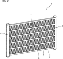
- tubes 1 shown in FIG. 1 were prepared using 11 types of alloys A1-A11 having the chemical compositions shown in Table 1. Subsequently, heat exchangers 2 shown in FIG. 2 were assembled using the resulting tubes 1, and the brazeability and corrosion resistance of the resulting 11 types of heat exchangers 2 were evaluated. The details are explained below.
- Billets having the chemical compositions shown in Table 1 were each heated at 600°C for 10 hours to perform a homogenization treatment. After the homogenization treatment was completed, the billets were cooled to room temperature and then reheated to 450°C and hot extrusion was performed.
- tube main bodies 10, each comprising a plurality of refrigerant passageways 11 and having a cross section perpendicular to the extrusion direction that exhibits a flat shape were manufactured, as shown in FIG. 1 .
- a paste for forming coatings 12 was prepared by mixing the Si powder, the Zn powder, the first flux powder, the second flux powder, and the binder with a solvent.
- each component of each coating 12 is as below.
- the tubes 1 as shown in FIG. 1 were obtained by the above.
- Fins 3 having a corrugated shape were prepared by corrugating plate materials, each composed of an Al(1.2%)-Mn(1.5%)-Zn alloy and having a thickness of 0.1 mm. It is noted that the fin pitch was set to 3 mm, and the fin height was set to 7 mm.
- Brazing sheets each made of an aluminum alloy and clad with a filler material, were each formed into a pipe shape such that the filler material was on the outer side. Subsequently, holes, into which the tubes were inserted, were formed on a side surface. By the above, the headers 4 were obtained.
- each tube 1 Both ends of each tube 1 were inserted into the headers 4 while alternately stacking the tubes 1 and the fins 3, thereby assembling the prescribed shape shown in FIG. 2 .
- the tubes 1, the fins 3, and the headers 4 were joined, and thereby the heat exchangers 2 were obtained. Furthermore, the brazing was performed in a nitrogen-gas atmosphere, the temperature of the tubes 1, the fins 3, and the headers 4 was increased to 600°C at a temperature-increase rate of an average of 50°C/min, and the temperature of 600°C was held for 3 min, after which the temperature was lowered to room temperature.
- test bodies 1-11 showed satisfactory results for both brazeability and corrosion resistance.
- test body 1 and test bodies 6-9 showed superior corrosion resistance because they contain Zr, Cr, Ti, or Sr in addition to Mn, Cu and Si and because the content of these elements are within the above-specified ranges.
- the present example is an example of heat exchangers 2 in which the content of each component in the coating 12 was modified by modifying the composition of the paste for forming the coating 12.
- the tube main bodies 10 were prepared using alloy A1 in working example 1, and the tubes 1 were obtained by forming coatings B1-B25 having the compositions shown in Table 3; otherwise, the heat exchangers 2 were prepared the same as in working example 1.
- the resulting 25 types of heat exchangers 2 (test bodies 21-45), brazeability and corrosion resistance were evaluated the same as in working example 1. The results thereof are shown in Table 4.
- test bodies 21-35 show satisfactory results for both brazeability and corrosion resistance because coatings B1-B15 having the above-specified compositions were used.
- test body 36 a portion was created at which a fin 3 and a tube 1 could not be joined because coating B16, which has a low Si powder content, was used, and consequently the joint failed.
- test body 37 liquid-phase filler material was excessively produced because coating B 17, which has a high Si powder content, was used. As a result, melting of a fin 3 after brazing was confirmed.
- Test body 38 shows corrosion resistance equivalent to test body 28, which has approximately the same total amount of Zn. Nevertheless, the content of the first flux powder in test body 38 is low, and consequently the total amount of the powder mixture in test body 38 is greater than that in test body 28. As a result, shrinkage of the dimensions of the heat exchanger after brazing became excessively large.
- coating B19 in which the content of the first flux powder is high, was used, and consequently unreacted first flux powder remained after brazing and produced discoloring.
- test body 40 In test body 40, coating B20, in which the content of the second flux powder is low, was used; consequently a portion was created in which a fin 3 and a tube 1 could not be joined; therefore, the joint failed. In addition, discoloring occurred in test body 40.
- coating B21 in which the content of the second flux powder is high and the total amount of the powder mixture is more than 30 g/m 2 , was used; consequently, shrinkage of the dimensions of the heat exchanger after brazing became excessively large.
- test body 42 In test body 42, coating B22, in which the Zn powder content is low, was used, and consequently corrosion resistance was insufficient.
- coating B23 in which the Zn powder content is high, was used, and consequently preferential corrosion of the fillet occurred and detachment of a fin 3 occurred.
- test body 44 coating B24, in which the binder content is low, was used, and consequently peeling of the coating occurred when assembling the tube main bodies 10 into the heat exchanger. As a result, a fin 3 had joint failure.
Landscapes
- Engineering & Computer Science (AREA)
- Mechanical Engineering (AREA)
- Chemical & Material Sciences (AREA)
- Physics & Mathematics (AREA)
- Thermal Sciences (AREA)
- General Engineering & Computer Science (AREA)
- Materials Engineering (AREA)
- Organic Chemistry (AREA)
- Metallurgy (AREA)
- Inorganic Chemistry (AREA)
- Details Of Heat-Exchange And Heat-Transfer (AREA)
- Other Surface Treatments For Metallic Materials (AREA)
- Powder Metallurgy (AREA)
Abstract
Description
- The present invention relates to a heat-exchanger tube, to a heat exchanger in which the heat-exchanger tube is used, and to a brazing paste that is used in brazing the heat exchanger.
- Aluminum alloys that are lightweight and have high thermal conductivity are frequently used in automobile heat exchangers, such as in evaporators and condensers. A heat exchanger comprises tubes, through which a refrigerant flows, and fins for exchanging heat between the refrigerant and air on the outer side of the tubes; the tubes and the fins are joined by brazing. A fluoride flux is often used in the joining of the tubes and the fins.
- If a perforation occurs in a tube used in the automobile heat exchanger owing to corrosion during use, then refrigerant will leak out and, consequently, the heat exchanger will no longer be able to serve its function. Therefore, for the purpose of increasing corrosion resistance, a sacrificial-anode layer is formed on the surface of each tube. Conventionally, as a method that forms the sacrificial-anode layer, a method is used in which Zn (zinc) is adhered beforehand to the tube surface by thermal spraying or the like, and the Zn diffuses by heating during brazing. According to such a method, a Zn-diffusion layer, which constitutes a sacrificial anode, is formed on the tube surface after the brazing, which makes it possible to inhibit the progress of corrosion in the plate-thickness direction.
- Nevertheless, in the above-mentioned method, an operation that adheres Zn onto the surface of the tube beforehand becomes necessary. In addition, if the above-mentioned method is used, then a filler material must be provided on the fin side, and therefore it is necessary to manufacture the fins using cladding material cladded with filler material. Consequently, it is difficult to reduce the manufacturing cost, the materials cost, etc.
- A technique has been proposed (Patent Document 1) to solve these problems, wherein a flux layer that contains an Si (silicon) powder, a Zn-containing flux, and a binder is formed on the outer surface of the tube. The flux layer having the above-mentioned composition can be adhered simultaneously with all the filler material, Zn, and flux components in a single adhering process. In addition, because there is no need to provide filler material on the fin side, the fins can be prepared using bare-fin material. As a result, a cost reduction can be achieved.
- For example, if the above-mentioned flux layer containing KZnF3 as the Zn-containing flux is used, then the flux component and Zn are produced according to the following reaction formula.
• 6KZnF3 + 4Al → 3KAlF4 + K3AlF6 + 6Zn
(555°C or higher) - Based on the above reaction formula, the Zn-containing flux does not function alone as the Zn and flux components, but rather it functions as the Zn and flux components by precipitating Zn by reacting with the Al (aluminum) of the tube and by producing potassium aluminum fluorides, which are the flux components. Accordingly, if a Zn-containing flux is used, then the above-mentioned reaction progresses at the interface between the flux layer and the tube, that is, in the vicinity of the outer surface of the tube.
- In addition, as a technique that simultaneously adheres all the Zn and flux components in a single adhering process, a technique has been proposed (Patent Document 2), wherein a brazing composition, which is made by mixing Si powder, Zn powder, and K-Al-F flux, is applied to the outer surface of the tube. If this brazing composition is used, then a cost reduction can be achieved, the same as mentioned above.
-
- Patent Document 1 -
PCT Publication No. WO 2011/090059 - Patent Document 2 - Japanese Laid-open Patent Publication No.
2014-83570 - To reduce the burden on the environment, there has been increasing demand in recent years to improve the fuel consumption of automobiles by reducing the weight of the component parts. From such a viewpoint, with regards to heat-exchanger tubes whose wall thickness is thinner than in the conventional art, there is strong demand for corrosion resistance that is higher than in the conventional art. This means that a more highly concentrated, deeper Zn-diffusion layer must be formed by adhering a larger amount of Zn to the tube surface than in the conventional art and then heating such, thereby increasing the corrosion-protection life span by a sacrificial anode.
- Nevertheless, according to the technique of
Patent Document 1, because it would be necessary to increase the content of the Zn-containing flux that is adhered to the tube, the entire flux layer would become thick. In this case, because the Zn-containing flux reaction will proceed at the outer surface of the tube as described above, there would be a problem in that unreacted Zn-containing flux will remain in the vicinity of a surface-layer part of the flux layer, which unreacted Zn-containing flux is separated from the outer surface of the tube. This means that, even if a large amount of the Zn-containing flux is applied, there is a limit to the formation of a highly-concentrated, deep Zn-diffusion layer on the outer surface of the tube, which means that it is not expected to increase corrosion resistance. - On the other hand, in the technique of
Patent Document 2, the total amount of oxide film present on the surface of the Zn powder increases in proportion to the content of the Zn powder. Therefore, in the technique ofPatent Document 2, if an attempt is made to make the total amount of Zn in the flux layer the same as in the technique ofPatent Document 1, then it is necessary to increase the content of the K-Al-F flux in order to eliminate the oxide film present on the surface of the Zn powder. As a result of the above, the present inventors discovered that the total amount of Si powder, Zn powder, and K-Al-F flux contained in the flux layer becomes greater than in the case ofPatent Document 1. If the total amount of these powders and the flux is large, then the flux layer becomes thick, and consequently, when brazing is performed to join the tube and the fin, a clearance between the tube and the fin, which results when the flux layer melts due to the heating, becomes large, and, in turn, the dimensions of the entire heat exchanger are adversely reduced. Accordingly, to prevent such problems, it is preferable to make the thickness of the flux layer as thin as possible. - The present invention was conceived against this background, and an object of the present invention is to provide a heat-exchanger tube that has superior corrosion resistance, can prevent dimensional changes during brazing, and in which it is easy to reduce weight and cost; to provide a heat exchanger that uses the heat-exchanger tube; and to provide a brazing paste that is used in the manufacture of the heat exchanger.
- In one aspect of the invention, a heat-exchanger tube comprises:
- a tube main body composed of an aluminum alloy; and
- a coating applied onto a surface of the tube main body;
- the coating contains a powder mixture-which includes: 1 g/m2 or more and 7 g/m2 or less of an Si powder, 0.2 g/m2 or more and 4.0 g/m2 or less of a Zn powder, 0.5 g/m2 or more and 5.0 g/m2 or less of a first flux powder composed of a compound that contains Zn, and 5 g/m2 or more and 20 g/m2 or less of a second flux powder composed of a compound that does not contain Zn-and a binder;
- the total amount of the powder mixture in the coating is 30 g/m2 or less; and the proportion of the binder in the coating is 5-40 mass%.
- Another aspect of the invention is a heat exchanger manufactured using the heat-exchanger tube, wherein
a fin, a header, and the heat-exchanger tube, which are composed of aluminum alloy, are joined by brazing. - Yet another aspect of the invention is a brazing paste for manufacturing the coating on the heat-exchanger tube according to the above-mentioned aspects.
- The heat-exchanger tube (hereinbelow, called the "tube" where appropriate) comprises the tube main body composed of an aluminum alloy. Consequently, the tube is lightweight and has superior thermal conductivity.
- In addition, the coating includes the powder mixture, which includes the four types of powders, that is, the Si (silicon) powder, the Zn (zinc) powder, the first flux powder, and the second flux powder. These four types of powders each exhibit their respective characteristics; in addition, they exhibit synergistic effects by interacting with one another, and thereby superior brazeability and corrosion resistance can be easily achieved.
- That is, owing to the heating during brazing, the Si powder included in the above-mentioned powder mixture reacts with the Al of the above-mentioned tube main body, and thereby liquid-phase filler material composed of an Al-Si alloy can be produced. Thereby, the above-mentioned tube and the above-mentioned fin can be joined together.
- Because the above-mentioned first flux powder is composed of a compound that contains Zn, it reacts with the Al of the above-mentioned tube main body, owing to the heating during brazing, to produce the flux component(s) and Zn. Thereby, brazing becomes possible and the Zn diffuses into the above-mentioned tube main body to form a Zn-diffusion layer. Furthermore, owing to the formation of the Zn-diffusion layer, an electric-potential gradient can be formed in which, from the surface to a deep part of the above-mentioned tube main body, the surface becomes a lower potential and the deep part becomes a higher potential, and thus the surface-layer part serves as a sacrificial anode and the deep part can be protected against corrosion.
- Nevertheless, as described above, because the reaction of the first flux powder proceeds at the outer surface of the tube main body, if the content of the first flux powder is made large in order to obtain higher corrosion resistance, then the coating as a whole becomes thick. As a result, the first flux powder would tend to remain in an unreacted state in the vicinity of the surface-layer part of the coating, which is separated from the outer surface of the tube main body. Thus, even if the content of the first flux powder is increased, it is difficult to form, on the surface of the tube main body, a Zn-diffusion layer that has a high concentration and is deep.
- In the present invention, in order to compensate for the insufficiency of the Zn amount while preventing the unreacted first flux powder from remaining, the content of the first flux powder is reduced, and the Zn amount that has become insufficient due to the reduction of the first flux powder is compensated for by the Zn powder. In addition, in the present invention, the oxide film remaining on the surface of the Zn powder is eliminated during brazing, and the second flux powder is further admixed in order to wet the surface of the tube main body.
- In the present invention, the powder mixture has the above-specified composition, and thereby, in addition to the Zn produced by the first flux powder reacting with the Al of the tube main body, the Zn produced by the melting of the Zn powder also diffuses into the tube main body. As a result, a Zn-diffusion layer that has a high concentration and is deep can be formed on the surface of the tube main body, and thereby corrosion resistance can be increased.
- On the other hand, if an attempt were to be made to obtain the Zn amount needed to form the Zn-diffusion layer by mixing the second flux powder and the Zn powder without using the first flux powder, then a large amount of the Zn powder would be needed. Attendant with that, because the total amount of the oxide film of the Zn powder also would increase, it would be necessary to increase the content of the second flux powder to eliminate that increased portion of the oxide film. In the present invention, by admixing the above-mentioned first flux powder, the content of the Zn powder can be decreased. As a result, in addition to the Zn powder, the content of the second flux powder also can be decreased and, in turn, the total amount of the powder mixture can be decreased. Furthermore, the coating as a whole can be made thin by reducing the total amount of the powder mixture and, when brazing is performed, the clearance between the tube and the fin, which is created by the melting of the above-mentioned coating due to the heating, can be decreased. As a result, it is possible to prevent a decrease in the dimensions of the overall core of the resulting heat exchanger.
- As described above, the tube has superior corrosion resistance because a Zn-diffusion layer that has a high concentration and is deep can be easily formed. In addition, the wall thickness of the tube can be made thin while ensuring sufficient corrosion resistance, and thereby the tube easily can be made lightweight. Therefore, the tube can be suitably used, for example, for use in automobiles, which are in severely corrosive environments.
- In addition, in the heat exchanger, the heat-exchanger tube, and the fin and header, which are composed of aluminum alloy, are joined by brazing. Therefore, as described above, it has superior corrosion resistance and easily can be made lightweight.
-
-
FIG. 1 is an oblique view of a heat-exchanger tube according to working example 1. -
FIG. 2 is an oblique view of a heat exchanger that was prepared using the heat-exchanger tube according to working example 1. - The configuration of the above-mentioned tube is explained in detail below.
- The configuration of the tube main body is not particularly limited and can be selected as appropriate in accordance with the application, the required characteristics, etc. For example, the tube main body can be formed by extrusion and can be configured as an extruded multi-hole pipe having a plurality of refrigerant passageways internally. In addition, the tube main body may have a shape such as a simple tube shape. In this case, the tube main body may be manufactured by extrusion or may be manufactured by bending a plate material.
- The tube main body is composed of an aluminum alloy. Here, the above-mentioned "aluminum alloy" is a general term that includes both pure aluminum and aluminum alloys. Aluminum alloys of various chemical compositions can be utilized as the aluminum alloy used in the tube main body.
- For example, a chemical composition that is restricted to Cu: 0.05% (mass%, likewise below) or less, the balance being Al and unavoidable impurities, can serve as the chemical composition of the above-mentioned aluminum alloy. The preferred content ranges and the like of each element based on this chemical composition are explained below.
- Cu is mixed in, to a certain extent, as an unavoidable impurity. If the Cu content of the tube main body is large, then there is a risk that the intrinsic corrosion resistance of the tube main body will decrease. Consequently, from the viewpoint of increasing corrosion resistance, the Cu content is preferably restricted to 0.05% or less.
- It is known in the conventional art that, when Zn is added to Al, the electric potential is made lower, and when Cu or Si is added, the electric potential is made higher. The present inventors discovered that, in the case in which Zn, Cu, and Si coexist, the effect of making the electric potential higher-owing to the synergistic effect of Cu and Si-becomes large as compared to the case in which Cu or Si are present alone; therefore it becomes difficult to obtain the effect of increasing corrosion resistance using Zn.
- That is, if brazing is performed using the above-mentioned tube, a Zn-diffusion layer is formed by the diffusion of Zn in the depth direction from the surface of the tube main body. Furthermore, simultaneous with the diffusion of Zn, Si supplied from Si particles also diffuses in the depth direction, and thereby an Si diffusion layer is formed. Consequently, if the Cu content included in the tube main body is excessively large with respect to the Zn concentration in the above-mentioned Zn-diffusion layer, then the effect of Zn making the electric potential lower is offset by the effect of the Si diffusion layer and Cu making the electric potential higher; therefore it becomes difficult to make the electric potential on the surface side of the tube main body much lower than the electric potential of the deep part.
- On the other hand, if the amount of Zn powder in a coating is increased in order to make the effect of Zn causing the electric potential to be lower to be greater than the effect of the Si diffusion layer and Cu making the electric potential higher, then the total amount of the oxide film present on the surface of the Zn powder also increases. In this case, the content of the above-mentioned second flux powder must be increased in order to eliminate that portion of the oxide film that was added, and consequently the above-mentioned coating becomes thick. As a result, the clearance between the above-mentioned tube and the above-mentioned fin created by the melting of the above-mentioned coating due to the heating becomes large, and consequently there is a risk that the decrease in the dimensions of the entire core of the heat exchanger will become excessive.
- Accordingly, to avoid such a problem and to increase corrosion resistance, it is necessary to both increase the intrinsic corrosion resistance of the tube main body by decreasing the Cu content and to form an electric-potential gradient in which the surface side of the tube main body is a sufficiently lower potential than that of the deep part. By restricting the Cu content to 0.05% or less, such an electric-potential gradient can be implemented and thereby corrosion resistance increased. From the same viewpoint, it is more preferable to restrict the Cu content to 0.03% or less, and yet more preferable to restrict the Cu content to 0.01 % or less.
- The above-mentioned aluminum alloy may further contain Mn: 0.1%-1.2%. Mn functions to increase strength by solid so luting Mn in the Al matrix. By making the Mn content 0.1% or more, a sufficient strength-increasing effect can be obtained. On the other hand, if the Mn content is more than 1.2%, then workability during extrusion decreases, and consequently there is a risk that the efficiency of production of the above-mentioned tube main body will decrease. Accordingly, from the viewpoint of combining both strength and productivity, the Mn content is preferably 0.1%-1.2% and more preferably 0.2%-1.0%.
- The above-mentioned aluminum alloy may further contain Zr: 0.01%-0.30%. When the aluminum alloy of the tube main body recrystallizes due to the heating during brazing, Zr functions to coarsen the recrystallized grains and thereby reduce the grain-boundary density. If the Zr content is 0.01 % or more, then it is possible to prevent the liquid-phase filler material of the Al-Si alloy produced during the brazing from infiltrating into the crystal-grain boundaries of the matrix and thereby to prevent preferential corrosion at the grain boundaries from occurring. On the other hand, if the Zr content is more than 0.30%, then huge crystallized products are produced during casting and there is a risk that it will become difficult to manufacture a suitable tube main body. Accordingly, the Zr content is preferably 0.01%-0.30%.
- The above-mentioned aluminum alloy may further contain Cr: 0.01%-0.30%. Cr functions to coarsen the recrystallized grains and thereby to decrease grain-boundary density, the same as in Zr. By setting the Cr content to 0.01 % or more, it is possible to prevent the occurrence of preferential corrosion at the grain boundaries. On the other hand, if the Cr content is more than 0.30%, then huge crystallized products are produced during casting, and consequently there is a risk that it will be difficult to manufacture a suitable tube main body. Accordingly, the Cr content is preferably 0.01%-0.30%.
- The above-mentioned aluminum alloy may further contain Ti: 0.01%-0.30%. If the aluminum alloy contains Ti, then high-concentration regions, in which the Ti concentration is comparatively high, and low-concentration regions, in which the Ti concentration is comparatively low, are alternately layered in the wall-thickness direction. The low-concentration regions tend to corrode more than the high-concentration regions, and consequently the progress of corrosion in the wall-thickness direction is reduced by the formation of the low Ti concentration regions in a laminar manner. As a result, pitting-corrosion resistance and grain-boundary-corrosion resistance are increased. In addition, Ti functions to increase strength at room temperature and at high temperature. To sufficiently obtain these effects, the Ti content is preferably 0.01 % or more. On the other hand, if the Ti content is more than 0.30%, then huge crystallized products are produced during casting, and consequently there is a risk that it will become difficult to manufacture a suitable tube main body. Accordingly, the Ti content is preferably 0.01%-0.30%.
- Sr functions to refine the structure of the eutectic that crystallizes when the liquid-phase filler material solidifies during cooling and to distribute that eutectic structure evenly. This eutectic structure becomes the anode site, and consequently the corrosion configuration can be made into a planar shape by the distribution of the eutectic structure. As a result, pitting-corrosion resistance can be increased. To sufficiently obtain the effect of increasing pitting-corrosion resistance, the Sr content is preferably 0.01% or more. On the other hand, if the Sr content is more than 0.10%, then Al-Si-Sr compounds crystallize, and consequently there is a risk that the refinement of the eutectic structure will become insufficient. Accordingly, the Sr content is preferably 0.01%-0.10%.
- By coexisting with Mn, Si precipitates an Al-Mn-Si intermetallic compound as heating is applied during brazing. The Al-Mn-Si intermetallic compound functions to coarsen the recrystallized grains, which makes it possible to reduce the grain-boundary density of the aluminum alloy. If the Si content is 0.05% or more, then Al-Mn-Si intermetallic compounds can be sufficiently precipitated. As a result, the liquid-phase filler material produced during brazing can be prevented from infiltrating the crystal-grain boundaries of the aluminum alloy, and thereby the occurrence of preferential corrosion at the grain boundaries can be further inhibited. On the other hand, if the Si content is more than 0.30%, then the electric potential of the tube main body becomes higher owing to solid so luting Si, and consequently there is a risk that corrosion resistance will decrease. Accordingly, the Si content is preferably 0.05%-0.30%.
- Zr, Cr, Ti, and Sr may be added independently or as a composite. If these elements are added as a composite, then the additive effects of the elements can be obtained.
- If the tube main body is manufactured by extrusion using an aluminum alloy that contains Mn, then it is preferable to use an aluminum alloy that has been subjected to a homogenization treatment under the conditions below.
- In a first aspect of the homogenization treatment, a homogenization treatment is performed in which an aluminum alloy ingot having the above-mentioned chemical composition is held at a temperature of 400°C-650°C for 2 hours or more. In this case, the coarse crystallized products formed during casting are decomposed or granulated, and thereby it is possible to homogenize the heterogeneous structures, such as segregation layers, produced during casting. As a result, resistance during extrusion can be reduced and thereby extrudability can be increased. In addition, the surface roughness of the product after extrusion can be reduced.
- If the hold temperature in the homogenization treatment is below 400°C, then there is a risk that coarse crystallized products, the above-mentioned heterogeneous structures, or the like will remain, and there is a risk that such will lead to a decrease in extrudability, an increase in surface roughness, or the like. The higher the hold temperature in the homogenization treatment, the more that the hold time can be shortened and thereby the more that productivity can be increased. However, if the hold temperature is above 650°C, there is a risk that such will lead to the melting of the ingot. Accordingly, the hold temperature in the homogenization treatment is preferably 400°C-650°C. From the same viewpoint, the hold temperature in the homogenization treatment is preferably 430°C-620°C.
- In addition, from the viewpoint of sufficiently performing the homogenization, the hold time in the homogenization treatment is preferably 3 hours or more. On the other hand, if the hold time is more than 24 hours, then the homogenization effect becomes saturated, and consequently it is difficult to obtain an effect commensurate with the hold time. Accordingly, the hold time in the homogenization treatment is preferably 3-24 hours.
- In a second aspect of the homogenization treatment, a first homogenization treatment, in which the ingot is held at a comparatively high temperature, and a second homogenization treatment, in which the ingot is held at a temperature lower than that of the first homogenization treatment, may be performed in combination. In this case, hot extrudability can be further increased. In addition, in the extrusion, aluminum pieces that have accumulated in the die are discharged from the die when they reach a certain size, and thereby defects are produced by the adhesion of these aluminum pieces to the surface of the tube; however, the number of the above-mentioned defects can be reduced by utilizing the above-mentioned second aspect.
- The first homogenization treatment is preferably performed by holding the ingot at a temperature of 550°C-650°C for 2 hours or more. In this case, the coarse crystallized products formed during casting not only decompose or granulate but can also actively form solid solutes. Solid solute formation tends not to progress if the hold temperature in the first homogenization treatment is below 550°C. The higher the hold temperature in the first homogenization treatment, the shorter that the hold time becomes and thereby the more that the productivity can be increased. However, if the hold temperature in the first homogenization treatment is above 650°C, then there is a risk that the ingot will melt. Accordingly, the hold temperature in the first homogenization treatment is preferably 550°C-650°C. From the same viewpoint, the hold temperature in the first homogenization treatment is more preferably 580°C-620°C.
- In addition, by making the hold time in the
first homogenization treatment 2 hours or more, solid soluting of the crystallized products can be implemented sufficiently. If the hold time is less than 2 hours, then the above-mentioned effect becomes insufficient. On the other hand, if the hold time is more than 24 hours, then it is difficult to obtain an effect commensurate with the hold time. Accordingly, the hold time in the first homogenization treatment is preferably 2 hours or more and is more preferably 3-24 hours. - The second homogenization treatment is preferably performed by holding the ingot at a temperature of 400°C-550°C for 3 hours or more. In this case, the Mn that is solid soluted in the matrix is precipitated, and thereby the amount of solid solutes of Mn can be reduced. As a result, the deformation resistance in the extrusion decreases and thereby extrudability can be increased. If the hold temperature in the second homogenization treatment is below 400°C, then the amount of precipitated Mn becomes small, and consequently there is a risk that the effect of decreasing deformation resistance will become insufficient. On the other hand, if the hold temperature in the second homogenization treatment is above 550°C, then the Mn tends not to precipitate, and consequently there is a risk that the effect of decreasing deformation resistance will become insufficient.
- In addition, by setting the hold time in the second homogenization treatment to 3 hours or more, Mn can be sufficiently precipitated. If the hold time is less than 3 hours, then Mn precipitation becomes insufficient and consequently there is a risk that the effect of reducing deformation resistance will become insufficient. From the viewpoint of increasing extrudability, the hold time preferably is made long; however, if the hold time is more than 24 hours, then it is difficult to obtain an effect commensurate with the hold time. Accordingly, the hold time in the second homogenization treatment is preferably 3 hours or more, is more preferably 3-24 hours, and is yet more preferably 5-15 hours.
- In the above-mentioned second aspect, the first homogenization treatment and the second homogenization treatment may be performed successively, or the ingot may be temporarily cooled between the first homogenization treatment and the second homogenization treatment. In either case, the above-mentioned effect can be obtained. Furthermore, performing the first homogenization treatment and the second homogenization treatment successively means that, after the first homogenization treatment is complete, the second homogenization treatment is started without cooling the ingot to a temperature lower than the hold temperature in the second homogenization treatment. If the ingot is cooled after the first homogenization treatment, then the second homogenization treatment can be performed by, for example, reheating the ingot after cooling it to 200°C or lower.
- The coating present on the surface of the tube main body contains a powder mixture-which contains an Si powder, a Zn powder, a first flux powder composed of a compound that includes Zn, and a second flux powder composed of a compound that does not include Zn-and a binder. The coating can be formed by applying a paste, in which the powder mixture and the binder are mixed in a solvent, onto the tube main body and then drying the solvent. The application of the paste can be performed by, for example, a roll-coating method or the like.
- The total amount of the powder mixture contained in the coating is 30 g/m2 or less. If the total amount of the powder mixture is more than 30 g/m2, then the reduction of the volume caused by the melting of the powder mixture during brazing becomes excessively large. As a result, the clearance between the tube main body and the fin becomes large, and consequently there is a risk that the dimensions of the heat exchanger after brazing will shrink excessively. To avoid such a problem and from the viewpoint of increasing the dimensional accuracy of the resulting heat exchanger, the total amount of the powder mixture contained in the coating is 30 g/m2 or less.
- The Si powder reacts with the Al of the tube main body owing to the heating during brazing, thereby producing liquid-phase filler material composed of an Al-Si alloy. Thereby, the tube can be joined to the fin, the header, etc.
- The Si powder content is 1 g/m2 or more and 7 g/m2 or less. If the Si powder content is less than 1 g/m2, then the amount of liquid-phase filler material becomes insufficient, and consequently joint failures tend to occur. On the other hand, if the Si powder content is more than 7 g/m2, then the proportions of the Zn powder, the first flux powder, and the second flux powder with respect to the overall powder mixture become excessively small, and consequently the amount of Zn diffused into the tube main body, the total amount of the flux component, etc. become insufficient. As a result, there is a risk that problems, such as a decrease in corrosion resistance or a decrease in brazeability, will occur.
- In addition, in this case, there is a risk that problems, such as the Si powder being unable to react with the Al of the tube main body and therefore remaining in the liquid-phase filler material, or the corrosion of the tube main body becoming remarkable as the liquid-phase filler material is produced, will occur. From the viewpoint of avoiding such problems, the Si powder content is 1 g/m2 or more and 7 g/m2 or less. From the same viewpoint, the Si powder content is preferably 2 g/m2 or more and 6 g/m2 or less.
- The maximum particle size of the Si powder is preferably 100 µm or less, more preferably 75 µm or less, yet more preferably 50 µm or less, and in particular preferably 35 µm or less. If coarse Si powder is present, then there is a risk that melt holes will be produced owing to local melting of the Al-Si eutectic during brazing. By restricting the maximum particle size of the Si powder to the above-specified ranges, the fluidity of the liquid-phase filler material produced during the addition of heat in brazing can be increased, and the formation of melt holes can be prevented by preventing erosion of the tube main body.
- Furthermore, the maximum particle size of the Si powder is set to a value that is measured by a laser diffraction method. This applies likewise to the Zn powder, which is described below.
- The Zn powder functions as a Zn source for forming the Zn-diffusion layer on the surface of the tube main body. By using it in combination with the first flux component as the Zn sources, the Zn powder can form a Zn-diffusion layer that has a high concentration and is deep. In addition, as described above, by using the Zn powder in combination with the first flux powder, the total amount of the powder mixture can be reduced, and thereby a decrease in the dimensions of the overall core of the heat exchanger can be prevented.
- The Zn powder content is 0.2 g/m2 or more and 4.0 g/m2 or less. If the Zn powder content is less than 0.2 g/m2, then the amount of Zn that diffuses into the tube main body becomes insufficient, even considering the amount of the Zn supplied from the first flux powder, and this leads to a decrease in corrosion resistance. If the Zn powder content is more than 4.0 g/m2, then the Zn concentration of the fillet formed at the junction with the fin becomes excessively high, and consequently preferential corrosion tends to occur more in the fillet than in the Zn-diffusion layer of the tube main body. As a result, there is a risk that the fin will detach at an early stage owing to corrosion. Accordingly, from the viewpoint of both increasing corrosion resistance and preventing the detachment of the fin, the Zn powder content is 0.2 g/m2 or more and 4.0 g/m2 or less. From the same viewpoint, the Zn powder content is preferably 0.2 g/m2 or more and 3.8 g/m2 or less.
- The maximum particle size of the Zn powder is preferably 100 µm or less, more preferably 50 µm or less, yet more preferably 30 µm or less, and in particular preferably 15 µm or less. If coarse Zn powder is present, then there is a risk that melt holes will occur owing to local melting of the Al-Zn eutectic during brazing. By restricting the maximum particle size of the Zn powder to the above-specified ranges, the formation of melt holes can be prevented. In addition, if the maximum particle size of the Zn powder is in the above-specified ranges, then the liquid phase Zn tends to spread evenly when the Zn particles melt, and consequently the Zn-diffusion layer formed on the tube main body tends to become even.
- The first flux powder is composed of a compound that contains Zn. As described above, the first flux powder produces the flux component(s) and Zn by reacting with the Al of the tube main body. By using it in combination with the Zn powder and the second flux powder, the first flux powder can reduce the total amount of the powder mixture while maintaining the amount of Zn and the amount of flux supplied, as described above; in turn, the thickness of the coating can be reduced. In addition, the oxide film present on the surface of the Zn powder is effectively eliminated, and consequently a Zn-diffusion layer that has a high concentration and is deep can be formed.
- To obtain the effect of reducing the thickness of the coating and to completely react with the Al of the tube main body, the content of the first flux powder is 0.5 g/m2 or more and 5.0 g/m2 or less. If the content of the first flux powder is less than 0.5 g/m2, then the thickness of the coating cannot be sufficiently reduced. On the other hand, if the content of the first flux powder is more than 5.0 g/m2, then the coating becomes thick and unreacted first flux powder tends to remain in the vicinity of the surface-layer part of the coating. From the same viewpoint, the content of the first flux powder is preferably 0.5 g/m2 or more and less than 3.0 g/m2.
- For example, a K-Zn-F compound, such as KZnF3, can be used as the first flux powder. In addition, the average particle size of the first flux powder is not particularly limited; for example, a first flux powder having an average particle size of approximately 5 µm can be used. It is noted that the average particle size is set to a value that is measured by a laser diffraction method. This applies likewise to the second flux powder, which is described below.
- The second flux powder is composed of a compound that does not contain Zn. By using it in combination with the first flux powder and the Zn powder, the second flux powder can easily achieve both a reduction in the total amount of the powder mixture and the formation of a Zn-diffusion layer that has a high concentration and is deep, as described above.
- The content of the second flux powder is 5 g/m2 or more and 20 g/m2 or less. If the content of the second flux powder is less than 5 g/m2, then, even considering the amount of the flux component produced by the first flux powder, the total amount of the flux component becomes insufficient, and consequently brazeability decreases. In addition, in this case, there is a risk that the effect of eliminating the oxide film on the Zn powder surface will become insufficient, and consequently there is a risk that corrosion resistance will decrease. If the content of the second flux powder is more than 20 g/m2, then the effect of eliminating the oxide film on the Zn powder, the tube main body, and the like will become saturated and, moreover, the total amount of the powder mixture will become excessive, and consequently the thickness of the coating cannot be sufficiently reduced. Accordingly, to reduce the thickness of the coating while ensuring brazeability, the content of the second flux powder is 5 g/m2 or more and 20 g/m2 or less. From the same viewpoint, it is preferably 6 g/m2 or more and 18 g/m2 or less.
- For example, a K-Al-F compound, such as KAlF4, K2AlF5, or K3AlF6, can be used as the second flux powder. These compounds may be used alone or in combination. The average particle size of the second flux powder is not particularly limited; for example, a second flux powder having an average particle size of approximately 5 µm can be used.
- For example, an acrylic resin, a urethane resin, or the like can be used as the binder. The proportion of the binder content with respect to the overall coating (with respect to 100 mass% of the total amount of the above-mentioned powder mixture and binder) is 5-40 mass%. If the binder content is less than 5 mass%, then detachment of the coating tends to occur. On the other hand, if the binder content is more than 40 mass%, then the thermal decomposition of the binder becomes insufficient, and there is a risk that undecomposed binder and the like will remain when brazing is performed. As a result, there is a risk that brazeability will be decreased.
- The paste for forming the above-mentioned coating preferably contains the above-mentioned Si powder, the above-mentioned Zn powder, the above-mentioned first flux powder, the above-mentioned second flux powder, and the above-mentioned binder. In addition, the paste may contain a solvent or the like in order to adjust the coatability onto the tube-main-body part. The preferred aspects of these powders are as described above.
- The content of each component in the paste can be appropriately set such that it is in the above-specified ranges in the above-mentioned coating state. That is, the content of the Si powder, the content of the Zn powder, the content of the first flux powder, and the content of the second flux powder can be set to 1 part by mass or more and 7 parts by mass or less, 0.2 parts by mass or more and 4.0 parts by mass or less, 0.5 parts by mass or more and 5.0 parts by mass or less, and 5 parts by mass or more and 20 parts by mass or less, respectively. In addition, the binder content may be 5 mass% or more and 40 mass% with respect to the total mass of the above-mentioned four types of powders and the binder.
- In addition, as described above, from the viewpoint of obtaining the effect of reducing the thickness of the coating and completely reacting with the Al of the tube main body, the content of the first flux powder in the paste is preferably 0.5 parts by mass or more and less than 3.0 parts by mass.
- The heat exchanger, in which tubes having the configuration described above are used, can be prepared by bringing fins, which are composed of aluminum alloy, into contact with the coating, then assembling other members, such as headers, and then heating and brazing these. The atmosphere, heating temperature, and times during brazing are not particularly limited, and the brazing method is also not particularly limited.
- Any well-known alloy can be used as the aluminum alloy used in the fins, as long as it has a strength and corrosion resistance sufficient for use in the heat exchanger.
- Working examples of the above-mentioned heat-exchanger tubes, and heat exchangers manufactured by using the above-mentioned heat-exchanger tubes, are explained below. In the present example,
tubes 1 shown inFIG. 1 were prepared using 11 types of alloys A1-A11 having the chemical compositions shown in Table 1. Subsequently,heat exchangers 2 shown inFIG. 2 were assembled using the resultingtubes 1, and the brazeability and corrosion resistance of the resulting 11 types ofheat exchangers 2 were evaluated. The details are explained below. - Billets having the chemical compositions shown in Table 1 were each heated at 600°C for 10 hours to perform a homogenization treatment. After the homogenization treatment was completed, the billets were cooled to room temperature and then reheated to 450°C and hot extrusion was performed. By the above, tube
main bodies 10, each comprising a plurality ofrefrigerant passageways 11 and having a cross section perpendicular to the extrusion direction that exhibits a flat shape, were manufactured, as shown inFIG. 1 . - Separate from the manufacture of the tube
main bodies 10, a paste for formingcoatings 12 was prepared by mixing the Si powder, the Zn powder, the first flux powder, the second flux powder, and the binder with a solvent. - The above-mentioned paste was applied, using a roll coater, to the flat surfaces of each tube
main body 10 obtained as mentioned above. Subsequently, the solvent was removed by drying the paste, thereby forming thecoating 12 on each tubemain body 10. It is noted that the content of each component of eachcoating 12 is as below. - Si powder (maximum particle size of 15 µm): 4 g/m2
- Zn powder (maximum particle size of 15 µm, average particle size of 3.4 µm): 1.5 g/m2
- First flux powder (KZnF3): 2.5 g/m2
- Second flux powder (a mixture of KAlF4 powder and K3AlF6 powder): 9 g/m2
- Binder: 25 mass% of overall coating
- The
tubes 1 as shown inFIG. 1 were obtained by the above. -
Fins 3, having a corrugated shape, were prepared by corrugating plate materials, each composed of an Al(1.2%)-Mn(1.5%)-Zn alloy and having a thickness of 0.1 mm. It is noted that the fin pitch was set to 3 mm, and the fin height was set to 7 mm. - Brazing sheets, each made of an aluminum alloy and clad with a filler material, were each formed into a pipe shape such that the filler material was on the outer side. Subsequently, holes, into which the tubes were inserted, were formed on a side surface. By the above, the
headers 4 were obtained. - Both ends of each
tube 1 were inserted into theheaders 4 while alternately stacking thetubes 1 and thefins 3, thereby assembling the prescribed shape shown inFIG. 2 . By heating and brazing in this state, thetubes 1, thefins 3, and theheaders 4 were joined, and thereby theheat exchangers 2 were obtained. Furthermore, the brazing was performed in a nitrogen-gas atmosphere, the temperature of thetubes 1, thefins 3, and theheaders 4 was increased to 600°C at a temperature-increase rate of an average of 50°C/min, and the temperature of 600°C was held for 3 min, after which the temperature was lowered to room temperature. - Brazeability and corrosion resistance were evaluated using the 11 types of heat exchangers 2 (test bodies 1-11) obtained by the above. The evaluating methods are explained in detail below.
- The joined state of the
fins 3, the presence/absence of external-appearance defects such as discoloring, and the presence/absence of melting of thefins 3 were checked by visual observation. The results thereof are shown in Table 2. Furthermore, those for which there was no problem in the visual observation are denoted in Table 2 as "Good." - The SWAAT test stipulated in ASTM G85 Annex A3 was performed for 1000 hours on each test body. After the tests were complete, the maximum corrosion depth was measured by observing a cross section of each sample using a microscope, and the presence/absence of the detachment of the
fins 3 was judged visually. The results thereof are shown in Table 2. It is noted that those having a maximum corrosion depth of 0.05 mm or less were judged to be "A+," those having a maximum corrosion depth of more than 0.05 mm and less than 0.10 mm were judged to be "A," those having a maximum corrosion depth of more than 0.10 mm and less than 0.20 mm were judged to be "B," and those having a maximum corrosion depth of more than 0.20 mm were judged to be "C." - As can be understood from Table 1 and Table 2, test bodies 1-11 showed satisfactory results for both brazeability and corrosion resistance. In particular,
test body 1 and test bodies 6-9 showed superior corrosion resistance because they contain Zr, Cr, Ti, or Sr in addition to Mn, Cu and Si and because the content of these elements are within the above-specified ranges. - The present example is an example of
heat exchangers 2 in which the content of each component in thecoating 12 was modified by modifying the composition of the paste for forming thecoating 12. In the present example, the tubemain bodies 10 were prepared using alloy A1 in working example 1, and thetubes 1 were obtained by forming coatings B1-B25 having the compositions shown in Table 3; otherwise, theheat exchangers 2 were prepared the same as in working example 1. Using the resulting 25 types of heat exchangers 2 (test bodies 21-45), brazeability and corrosion resistance were evaluated the same as in working example 1. The results thereof are shown in Table 4. - As can be understood from Table 3 and Table 4, test bodies 21-35 show satisfactory results for both brazeability and corrosion resistance because coatings B1-B15 having the above-specified compositions were used.
- In test body 36, a portion was created at which a
fin 3 and atube 1 could not be joined because coating B16, which has a low Si powder content, was used, and consequently the joint failed. - In test body 37, liquid-phase filler material was excessively produced because coating B 17, which has a high Si powder content, was used. As a result, melting of a
fin 3 after brazing was confirmed. - Test body 38 shows corrosion resistance equivalent to test body 28, which has approximately the same total amount of Zn. Nevertheless, the content of the first flux powder in test body 38 is low, and consequently the total amount of the powder mixture in test body 38 is greater than that in test body 28. As a result, shrinkage of the dimensions of the heat exchanger after brazing became excessively large.
- In test body 39, coating B19, in which the content of the first flux powder is high, was used, and consequently unreacted first flux powder remained after brazing and produced discoloring.
- In test body 40, coating B20, in which the content of the second flux powder is low, was used; consequently a portion was created in which a
fin 3 and atube 1 could not be joined; therefore, the joint failed. In addition, discoloring occurred in test body 40. - In test body 41, coating B21, in which the content of the second flux powder is high and the total amount of the powder mixture is more than 30 g/m2, was used; consequently, shrinkage of the dimensions of the heat exchanger after brazing became excessively large.
- In test body 42, coating B22, in which the Zn powder content is low, was used, and consequently corrosion resistance was insufficient.
- In test body 43, coating B23, in which the Zn powder content is high, was used, and consequently preferential corrosion of the fillet occurred and detachment of a
fin 3 occurred. - In test body 44, coating B24, in which the binder content is low, was used, and consequently peeling of the coating occurred when assembling the tube
main bodies 10 into the heat exchanger. As a result, afin 3 had joint failure. - In test body 45, coating B25, in which the binder content is high, was used, and consequently the fluidity of the liquid-phase filler material during brazing decreased. As a result, a
fin 3 had joint failure. In addition, discoloring of the surfaces of thetubes 1 caused by un-decomposed binder residue was observed.Table 1 Alloy Chemical Composition (mass%) Mn Cu Zr Cr Ti Sr Si Al A1 0.82 0.05 0.03 <0.01 <0.01 <0.01 0.12 Bal. A2 0.05 0.03 <0.01 <0.01 <0.01 <0.01 0.03 Bal. A3 0.39 0.05 <0.01 <0.01 <0.01 <0.01 0.03 Bal. A4 0.82 0.04 <0.01 <0.01 <0.01 <0.01 0.20 Bal. A5 0.97 0.03 <0.01 <0.01 <0.01 <0.01 0.12 Bal. A6 0.74 0.04 0.13 <0.01 <0.01 <0.01 0.12 Bal. A7 0.83 0.03 <0.01 0.12 <0.01 <0.01 0.12 Bal. A8 0.69 0.02 <0.01 <0.01 0.15 <0.01 0.12 Bal. A9 0.68 0.03 <0.01 <0.01 <0.01 0.06 0.12 Bal. A10 0.97 0.03 <0.01 <0.01 0.02 <0.01 0.03 Bal. A11 0.86 0.01 <0.01 <0.01 <0.01 0.05 0.35 Bal. Table 2 Test Body Alloy Used Brazeability Evaluation Corrosion-Resistance Evaluation Max. Corrosion Depth (mm) Judgment Presence/Absence of Detachment of Fin 3Test Body 1A1 Good 0.04 A+ None Test Body 2 A2 Good 0.11 B None Test Body 3 A3 Good 0.12 B None Test Body 4 A4 Good 0.06 A None Test Body 5 A5 Good 0.07 A None Test Body 6 A6 Good 0.03 A+ None Test Body 7 A7 Good 0.04 A+ None Test Body 8 A8 Good 0.04 A+ None Test Body 9 A9 Good 0.03 A+ None Test Body 10 A10 Good 0.08 A None Test Body 11 A11 Good 0.07 A None Table 3 Coating Powder Mixture Binder Amount of Coating Applied (g/m2) Si Powder First Flux Powder Second Flux Powder Zn Powder Total Amount of Powder Mixture (g/m2) Proportion in Coating (mass%) Content (g/m2) Content (g/m2) Max. Particle Size (µm) Content (g/m2) Content (g/m2) Content (g/m2) Max. Particle Size (µm) Avg. Particle Size (µm) B1 1 13 2.5 9 1.6 14 3.5 14.1 15 2.5 16.6 B2 7 10 2.5 10 1.5 15 3.2 21.0 30 9.0 30.0 B3 3 97 2.3 9 1.0 14 3.3 15.3 25 5.1 20.4 B4 6 75 2.4 8 1.4 13 3.5 17.8 10 2.0 19.8 B5 4 31 2.5 9 1.5 13 3.2 17.0 35 9.2 26.2 B6 3 12 0.5 11 1.4 14 3.3 15.9 5 0.8 16.7 B7 4 12 1.0 10 1.3 13 3.1 16.3 30 7.0 23.3 B8 3 13 2.8 9 3.0 13 2.9 17.8 25 5.9 23.7 B9 3 12 3.0 9 1.3 13 3.1 16.3 20 4.1 20.4 B10 3 13 5.0 8 1.2 12 3.0 17.2 30 7.4 24.6 B11 4 13 2.4 5 0.2 13 3.2 11.6 40 7.7 19.3 B12 3 12 2.2 19 3.8 15 3.5 28.0 25 9.3 37.3 B13 5 10 2.5 8 1.4 98 15.3 16.9 25 5.6 22.5 B14 5 13 2.3 9 1.2 49 7.7 17.5 25 5.8 23.3 B15 3 12 2.1 10 1.3 30 5.2 16.4 25 5.5 21.9 B16 0.7 12 2.0 12 1.7 15 3.2 16.4 25 5.5 21.9 B17 8 11 2.1 10 1.4 13 3.3 21.5 25 7.2 28.7 B18 3 14 0.3 23 4.0 12 3.1 30.3 25 10.1 40.4 B19 4 11 6.0 10 1.6 11 3.0 21.6 35 11.6 33.2 B20 5 12 2.3 3 1.5 11 3.0 11.8 25 3.9 15.7 B21 4 12 2.1 23 1.5 14 3.3 30.6 30 13.1 43.7 B22 3 14 2.0 6 0.1 14 3.2 11.1 30 4.8 15.9 B23 4 15 2.5 18 4.4 15 3.6 28.9 30 12.4 41.3 B24 6 12 2.5 10 1.3 13 3.2 19.8 3 0.6 20.4 B25 5 11 2.0 10 1.2 14 3.2 18.2 45 14.9 33.1 Table 4 Test Body Coating Used Brazeability Evaluation Corrosion-Resistance Evaluation Max. Corrosion Depth (mm) Judgment Presence/Absence of Detachment of Fin 3Test Body 21 B1 Good 0.04 A+ None Test Body 22 B2 Good 0.04 A+ None Test Body 23 B3 Good 0.07 A None Test Body 24 B4 Good 0.05 A+ None Test Body 25 B5 Good 0.04 A+ None Test Body 26 B6 Good 0.08 A None Test Body 27 B7 Good 0.07 A None Test Body 28 B8 Good 0.04 A+ None Test Body 29 B9 Good 0.05 A+ None Test Body 30 B10 Good 0.03 A+ None Test Body 31 B11 Good 0.10 A None Test Body 32 B12 Good 0.02 A+ None Test Body 33 B13 Good 0.04 A+ None Test Body 34 B14 Good 0.05 A+ None Test Body 35 B15 Good 0.05 A+ None Test Body 36 B16 Fin joint failure 0.04 A+ None Test Body 37 B17 Melting of fin 0.05 A+ None Test Body 38 B18 Large dimensional shrinkage 0.04 A+ None Test Body 39 B19 Discoloring 0.03 A+ None Test Body 40 B20 Fin joint failure, discoloring 0.04 A+ None Test Body 41 B21 Large dimensional shrinkage 0.04 A+ None Test Body 42 B22 Good 0.21 C None Test Body 43 B23 Good 0.01 A+ Present Test Body 44 B24 Fin joint failure 0.04 A+ None Test Body 45 B25 Fin joint failure, discoloring 0.05 A+ None
Claims (16)
- A heat-exchanger tube, comprising:a tube main body composed of an aluminum alloy; anda coating applied onto a surface of the tube main body;wherein,the coating contains a powder mixture-which includes: 1 g/m2 or more and 7 g/m2 or less of an Si powder, 0.2 g/m2 or more and 4.0 g/m2 or less of a Zn powder, 0.5 g/m2 or more and 5.0 g/m2 or less of a first flux powder composed of a compound that contains Zn, and 5 g/m2 or more and 20 g/m2 or less of a second flux powder composed of a compound that does not contain Zn -and a binder;the total amount of the powder mixture in the coating is 30 g/m2 or less; andthe proportion of the binder in the coating is 5-40 mass%.
- The heat-exchanger tube according to claim 1, wherein the content of the first flux powder is 0.5 g/m2 or more and less than 3.0 g/m2.
- The heat-exchanger tube according to claim 1 or 2, wherein the first flux powder is composed of KZnF3.
- The heat-exchanger tube according to any one of claims 1 to 3, wherein the second flux powder is composed of a K-Al-F compound.
- The heat-exchanger tube according to any one of claims 1 to 4, wherein the Si powder has a maximum particle size of 100 µm or less.
- The heat-exchanger tube according to any one of claims 1 to 5, wherein the Zn powder has a maximum particle size of 100 µm or less.
- The heat-exchanger tube according to any one of claims 1 to 5, wherein the Zn powder has a maximum particle size of 50 µm or less.
- The heat-exchanger tube according to any one of claims 1 to 5, wherein the Zn powder has a maximum particle size of 30 µm or less.
- The heat-exchanger tube according to any one of claims 1 to 8, wherein the aluminum alloy has a chemical composition in which Cu is restricted to 0.05% (mass%, likewise below) or less, the balance being Al and unavoidable impurities.
- The heat-exchanger tube according to claim 9, wherein the aluminum alloy further contains Mn: 0.1-1.2%.
- The heat-exchanger tube according to claim 9 or 10, wherein the aluminum alloy further contains one type or two or more from among Zr: 0.01-0.30%, Cr: 0.01-0.30%, Ti: 0.01-0.30%, and Sr: 0.01-0.10%.
- The heat-exchanger tube according to any one of claims 9 to 11, wherein the aluminum alloy further contains 0.05-0.30% of Si.
- A heat exchanger manufactured using the heat-exchanger tube according to any one of claims 1 to 12, whereina fin, a header, and the heat-exchanger tube, which are composed of aluminum alloy, are joined by brazing.
- A brazing paste for manufacturing the coating on the heat-exchanger tube according to any one of claims 1 to 12.
- The brazing paste according to claim 14, containing:the powder mixture-which includes 1 part by mass or more and 7 parts by mass or less of the Si powder, 0.2 parts by mass or more and 4.0 parts by mass or less of the Zn powder, 0.5 parts by mass or more and 5.0 parts by mass or less of the first flux powder, and 5 parts by mass or more and 20 parts by mass or less of the second flux powder-and the binder;wherein,the binder content is 5-40 mass% with respect to the total of the powder mixture and the binder.
- The brazing paste according to claim 15, wherein the content of the first flux powder is 0.5 parts by mass or more and less than 3.0 parts by mass.
Priority Applications (1)
| Application Number | Priority Date | Filing Date | Title |
|---|---|---|---|
| PL15800648T PL3150327T3 (en) | 2014-05-26 | 2015-04-27 | Coated heat-exchanger tube, method for manufacturing a heat-exchanger, and solder paste used for coating on the heat-exchanger tube |
Applications Claiming Priority (2)
| Application Number | Priority Date | Filing Date | Title |
|---|---|---|---|
| JP2014108119 | 2014-05-26 | ||
| PCT/JP2015/062739 WO2015182318A1 (en) | 2014-05-26 | 2015-04-27 | Heat exchanger tube, heat exchanger, and brazing paste |
Publications (3)
| Publication Number | Publication Date |
|---|---|
| EP3150327A1 true EP3150327A1 (en) | 2017-04-05 |
| EP3150327A4 EP3150327A4 (en) | 2017-05-24 |
| EP3150327B1 EP3150327B1 (en) | 2018-07-25 |
Family
ID=54698658
Family Applications (1)
| Application Number | Title | Priority Date | Filing Date |
|---|---|---|---|
| EP15800648.6A Active EP3150327B1 (en) | 2014-05-26 | 2015-04-27 | Coated heat-exchanger tube, method for manufacturing a heat-exchanger, and solder paste used for coating on the heat-exchanger tube |
Country Status (12)
| Country | Link |
|---|---|
| US (1) | US20170205159A1 (en) |
| EP (1) | EP3150327B1 (en) |
| JP (1) | JP6438019B2 (en) |
| KR (1) | KR102296371B1 (en) |
| CN (1) | CN106457483B (en) |
| BR (1) | BR112016027342B1 (en) |
| DK (1) | DK3150327T3 (en) |
| ES (1) | ES2686873T3 (en) |
| MX (1) | MX378778B (en) |
| NO (1) | NO3150327T3 (en) |
| PL (1) | PL3150327T3 (en) |
| WO (1) | WO2015182318A1 (en) |
Families Citing this family (14)
| Publication number | Priority date | Publication date | Assignee | Title |
|---|---|---|---|---|
| WO2016017716A1 (en) | 2014-07-30 | 2016-02-04 | 株式会社Uacj | Aluminium alloy brazing sheet |
| EP3231545B1 (en) | 2014-12-11 | 2019-09-18 | UACJ Corporation | Brazing method |
| JP6186455B2 (en) | 2016-01-14 | 2017-08-23 | 株式会社Uacj | Heat exchanger and manufacturing method thereof |
| JP2018044694A (en) * | 2016-09-12 | 2018-03-22 | 株式会社Uacj | Precoat fin material and heat exchanger prepared therewith |
| JP7096638B2 (en) * | 2016-09-12 | 2022-07-06 | 株式会社Uacj | Pre-coated fins and heat exchangers using them |
| JP6312968B1 (en) | 2016-11-29 | 2018-04-18 | 株式会社Uacj | Brazing sheet and method for producing the same |
| JP7053281B2 (en) | 2017-03-30 | 2022-04-12 | 株式会社Uacj | Aluminum alloy clad material and its manufacturing method |
| JP2019034334A (en) * | 2017-08-22 | 2019-03-07 | 株式会社ケーヒン・サーマル・テクノロジー | Manufacturing method of heat exchanger |
| JP2019070499A (en) * | 2017-10-11 | 2019-05-09 | 株式会社ケーヒン・サーマル・テクノロジー | Method of manufacturing heat exchanger |
| JP7199883B2 (en) | 2018-09-10 | 2023-01-06 | 株式会社Uacj | Pre-coated aluminum material and aluminum composite material |
| CN110369818B (en) * | 2019-08-05 | 2022-03-04 | 大连爱碧克空调配件有限公司 | Aluminum alloy bracket welding method |
| CN112935617A (en) * | 2019-12-10 | 2021-06-11 | 深圳市聚飞光电股份有限公司 | Solder for LED die bonding, preparation method thereof and LED die bonding method |
| JP7521943B2 (en) * | 2020-06-11 | 2024-07-24 | 株式会社Uacj | Aluminum alloy extruded multi-hole tube for heat exchanger and its manufacturing method |
| KR102490680B1 (en) * | 2022-07-04 | 2023-01-26 | 주식회사 삼원 | Paste composition for improving corrosion resistance of aluminum extruded tubes for heat exchangers and it is also using the Paste composition to manufacture heat exchanger extruded tube |
Family Cites Families (11)
| Publication number | Priority date | Publication date | Assignee | Title |
|---|---|---|---|---|
| JP3328923B2 (en) * | 1997-01-24 | 2002-09-30 | 日本軽金属株式会社 | Manufacturing method of aluminum heat exchanger core |
| US6497770B2 (en) * | 2000-02-17 | 2002-12-24 | Toyo Aluminium Kabushiki Kaisha | Flux-containing compositions for brazing aluminum, films and brazing method thereby |
| JP4115132B2 (en) * | 2002-01-11 | 2008-07-09 | 日本パーカライジング株式会社 | Aluminum alloy heat exchanger that resists odorous components |
| US8640766B2 (en) * | 2003-05-06 | 2014-02-04 | Mitsubishi Aluminum Co., Ltd. | Heat exchanger tube |
| KR20110133057A (en) * | 2003-10-20 | 2011-12-09 | 후루카와 스카이 가부시키가이샤 | Flat multi-vessel made of aluminum alloy and its manufacturing method |
| US7722922B2 (en) * | 2003-10-20 | 2010-05-25 | Furukawa-Sky Aluminum Corp. | Coating apparatus for an aluminum alloy heat exchanger member, method of producing a heat exchanger member, and aluminum alloy heat exchanger member |
| JP2011090059A (en) | 2009-10-20 | 2011-05-06 | Sumitomo Rubber Ind Ltd | Cleaning blade for image forming apparatus |
| JP5670100B2 (en) * | 2010-05-25 | 2015-02-18 | 株式会社Uacj | Method for producing aluminum alloy heat exchanger |
| JP5750237B2 (en) * | 2010-05-25 | 2015-07-15 | 株式会社Uacj | Method for producing aluminum alloy heat exchanger |
| JP5628266B2 (en) * | 2012-10-24 | 2014-11-19 | ハリマ化成株式会社 | Tube for heat exchanger, heat exchanger and coating film manufacturing method |
| JP6090736B2 (en) * | 2012-10-26 | 2017-03-08 | 株式会社Uacj | Aluminum alloy brazing method and flux component-coated aluminum alloy member |
-
2015
- 2015-04-27 BR BR112016027342-7A patent/BR112016027342B1/en active IP Right Grant
- 2015-04-27 NO NO15800648A patent/NO3150327T3/no unknown
- 2015-04-27 PL PL15800648T patent/PL3150327T3/en unknown
- 2015-04-27 MX MX2016015328A patent/MX378778B/en unknown
- 2015-04-27 JP JP2016523394A patent/JP6438019B2/en active Active
- 2015-04-27 EP EP15800648.6A patent/EP3150327B1/en active Active
- 2015-04-27 ES ES15800648.6T patent/ES2686873T3/en active Active
- 2015-04-27 KR KR1020167034971A patent/KR102296371B1/en active Active
- 2015-04-27 WO PCT/JP2015/062739 patent/WO2015182318A1/en not_active Ceased
- 2015-04-27 US US15/313,198 patent/US20170205159A1/en not_active Abandoned
- 2015-04-27 DK DK15800648.6T patent/DK3150327T3/en active
- 2015-04-27 CN CN201580025512.6A patent/CN106457483B/en active Active
Also Published As
| Publication number | Publication date |
|---|---|
| WO2015182318A1 (en) | 2015-12-03 |
| DK3150327T3 (en) | 2018-10-08 |
| NO3150327T3 (en) | 2018-12-22 |
| EP3150327A4 (en) | 2017-05-24 |
| MX378778B (en) | 2025-03-10 |
| JP6438019B2 (en) | 2018-12-12 |
| KR102296371B1 (en) | 2021-09-02 |
| EP3150327B1 (en) | 2018-07-25 |
| PL3150327T3 (en) | 2018-11-30 |
| CN106457483B (en) | 2019-07-26 |
| ES2686873T3 (en) | 2018-10-22 |
| MX2016015328A (en) | 2017-07-04 |
| JPWO2015182318A1 (en) | 2017-04-20 |
| US20170205159A1 (en) | 2017-07-20 |
| CN106457483A (en) | 2017-02-22 |
| BR112016027342B1 (en) | 2021-05-18 |
| KR20170013284A (en) | 2017-02-06 |
Similar Documents
| Publication | Publication Date | Title |
|---|---|---|
| EP3150327B1 (en) | Coated heat-exchanger tube, method for manufacturing a heat-exchanger, and solder paste used for coating on the heat-exchanger tube | |
| CN103038014B (en) | The manufacture method of aluminum alloy heat exchanger | |
| JP5670100B2 (en) | Method for producing aluminum alloy heat exchanger | |
| EP2543951B1 (en) | Heat exchanger constituted of aluminum alloy | |
| CN106170571B (en) | Aluminum cladding material and its manufacturing method, aluminum cladding material for heat exchanger and its manufacturing method, and aluminum heat exchanger using the aluminum cladding material for heat exchanger and its manufacturing method | |
| US20110240280A1 (en) | Aluminum alloy brazing sheet and heat exchanger | |
| JP5115963B2 (en) | Aluminum heat exchanger member with excellent corrosion resistance and method for producing aluminum heat exchanger with excellent corrosion resistance | |
| EP3418408A1 (en) | Aluminum alloy brazing sheet, manufacturing method therefor, and manufacturing method for vehicle heat exchanger using said brazing sheet | |
| EP3321384B1 (en) | Aluminum alloy cladding material, manufacturing method therefor, and heat exchanger using said aluminum alloy cladding material | |
| JP5279278B2 (en) | Brazing sheet for tube material of heat exchanger and method of manufacturing heat exchanger using the same | |
| EP3670688B1 (en) | Aluminum alloy-brazing sheet for heat exchanger | |
| EP3663423B1 (en) | Aluminum alloy brazing sheet for heat exchanger | |
| JP5632140B2 (en) | Aluminum alloy automotive heat exchanger and method of manufacturing the same | |
| JP6738667B2 (en) | Aluminum alloy heat exchanger excellent in corrosion resistance in atmospheric environment and method of manufacturing aluminum alloy heat exchanger | |
| JP7558004B2 (en) | Aluminum alloy extruded tubes and heat exchangers | |
| JP6738666B2 (en) | Aluminum alloy heat exchanger excellent in corrosion resistance in atmospheric environment and method of manufacturing aluminum alloy heat exchanger | |
| JP7519238B2 (en) | Aluminum alloy extruded tubes and heat exchangers | |
| WO2023063065A1 (en) | Aluminum alloy clad material for heat exchanger | |
| JP2023026898A (en) | Aluminum alloy extruded tube and heat exchanger |
Legal Events
| Date | Code | Title | Description |
|---|---|---|---|
| STAA | Information on the status of an ep patent application or granted ep patent |
Free format text: STATUS: THE INTERNATIONAL PUBLICATION HAS BEEN MADE |
|
| PUAI | Public reference made under article 153(3) epc to a published international application that has entered the european phase |
Free format text: ORIGINAL CODE: 0009012 |
|
| STAA | Information on the status of an ep patent application or granted ep patent |
Free format text: STATUS: REQUEST FOR EXAMINATION WAS MADE |
|
| 17P | Request for examination filed |
Effective date: 20161227 |
|
| AK | Designated contracting states |
Kind code of ref document: A1 Designated state(s): AL AT BE BG CH CY CZ DE DK EE ES FI FR GB GR HR HU IE IS IT LI LT LU LV MC MK MT NL NO PL PT RO RS SE SI SK SM TR |
|
| AX | Request for extension of the european patent |
Extension state: BA ME |
|
| A4 | Supplementary search report drawn up and despatched |
Effective date: 20170424 |
|
| RIC1 | Information provided on ipc code assigned before grant |
Ipc: F28F 21/08 20060101ALI20170418BHEP Ipc: B23K 1/19 20060101ALI20170418BHEP Ipc: B23K 35/28 20060101ALI20170418BHEP Ipc: F28F 19/06 20060101ALI20170418BHEP Ipc: B23K 101/14 20060101ALI20170418BHEP Ipc: B23K 35/363 20060101AFI20170418BHEP Ipc: B23K 3/06 20060101ALI20170418BHEP Ipc: C22C 21/00 20060101ALI20170418BHEP Ipc: B23K 1/00 20060101ALI20170418BHEP Ipc: B23K 103/10 20060101ALI20170418BHEP Ipc: F28D 1/053 20060101ALI20170418BHEP |
|
| DAV | Request for validation of the european patent (deleted) | ||
| DAX | Request for extension of the european patent (deleted) | ||
| GRAP | Despatch of communication of intention to grant a patent |
Free format text: ORIGINAL CODE: EPIDOSNIGR1 |
|
| STAA | Information on the status of an ep patent application or granted ep patent |
Free format text: STATUS: GRANT OF PATENT IS INTENDED |
|
| INTG | Intention to grant announced |
Effective date: 20180220 |
|
| GRAJ | Information related to disapproval of communication of intention to grant by the applicant or resumption of examination proceedings by the epo deleted |
Free format text: ORIGINAL CODE: EPIDOSDIGR1 |
|
| GRAL | Information related to payment of fee for publishing/printing deleted |
Free format text: ORIGINAL CODE: EPIDOSDIGR3 |
|
| STAA | Information on the status of an ep patent application or granted ep patent |
Free format text: STATUS: REQUEST FOR EXAMINATION WAS MADE |
|
| GRAR | Information related to intention to grant a patent recorded |
Free format text: ORIGINAL CODE: EPIDOSNIGR71 |
|
| STAA | Information on the status of an ep patent application or granted ep patent |
Free format text: STATUS: GRANT OF PATENT IS INTENDED |
|
| GRAA | (expected) grant |
Free format text: ORIGINAL CODE: 0009210 |
|
| STAA | Information on the status of an ep patent application or granted ep patent |
Free format text: STATUS: THE PATENT HAS BEEN GRANTED |
|
| INTC | Intention to grant announced (deleted) | ||
| AK | Designated contracting states |
Kind code of ref document: B1 Designated state(s): AL AT BE BG CH CY CZ DE DK EE ES FI FR GB GR HR HU IE IS IT LI LT LU LV MC MK MT NL NO PL PT RO RS SE SI SK SM TR |
|
| INTG | Intention to grant announced |
Effective date: 20180618 |
|
| REG | Reference to a national code |
Ref country code: GB Ref legal event code: FG4D |
|
| GRAS | Grant fee paid |
Free format text: ORIGINAL CODE: EPIDOSNIGR3 |
|
| REG | Reference to a national code |
Ref country code: CH Ref legal event code: EP |
|
| REG | Reference to a national code |
Ref country code: NO Ref legal event code: T2 Effective date: 20180725 |
|
| REG | Reference to a national code |
Ref country code: AT Ref legal event code: REF Ref document number: 1021241 Country of ref document: AT Kind code of ref document: T Effective date: 20180815 |
|
| REG | Reference to a national code |
Ref country code: IE Ref legal event code: FG4D |
|
| REG | Reference to a national code |
Ref country code: DE Ref legal event code: R096 Ref document number: 602015014140 Country of ref document: DE |
|
| REG | Reference to a national code |
Ref country code: RO Ref legal event code: EPE |
|
| REG | Reference to a national code |
Ref country code: DK Ref legal event code: T3 Effective date: 20181001 |
|
| REG | Reference to a national code |
Ref country code: ES Ref legal event code: FG2A Ref document number: 2686873 Country of ref document: ES Kind code of ref document: T3 Effective date: 20181022 |
|
| REG | Reference to a national code |
Ref country code: NL Ref legal event code: MP Effective date: 20180725 |
|
| REG | Reference to a national code |
Ref country code: LT Ref legal event code: MG4D |
|
| PG25 | Lapsed in a contracting state [announced via postgrant information from national office to epo] |
Ref country code: NL Free format text: LAPSE BECAUSE OF FAILURE TO SUBMIT A TRANSLATION OF THE DESCRIPTION OR TO PAY THE FEE WITHIN THE PRESCRIBED TIME-LIMIT Effective date: 20180725 |
|
| PG25 | Lapsed in a contracting state [announced via postgrant information from national office to epo] |
Ref country code: LT Free format text: LAPSE BECAUSE OF FAILURE TO SUBMIT A TRANSLATION OF THE DESCRIPTION OR TO PAY THE FEE WITHIN THE PRESCRIBED TIME-LIMIT Effective date: 20180725 Ref country code: FI Free format text: LAPSE BECAUSE OF FAILURE TO SUBMIT A TRANSLATION OF THE DESCRIPTION OR TO PAY THE FEE WITHIN THE PRESCRIBED TIME-LIMIT Effective date: 20180725 Ref country code: BG Free format text: LAPSE BECAUSE OF FAILURE TO SUBMIT A TRANSLATION OF THE DESCRIPTION OR TO PAY THE FEE WITHIN THE PRESCRIBED TIME-LIMIT Effective date: 20181025 Ref country code: GR Free format text: LAPSE BECAUSE OF FAILURE TO SUBMIT A TRANSLATION OF THE DESCRIPTION OR TO PAY THE FEE WITHIN THE PRESCRIBED TIME-LIMIT Effective date: 20181026 Ref country code: RS Free format text: LAPSE BECAUSE OF FAILURE TO SUBMIT A TRANSLATION OF THE DESCRIPTION OR TO PAY THE FEE WITHIN THE PRESCRIBED TIME-LIMIT Effective date: 20180725 Ref country code: IS Free format text: LAPSE BECAUSE OF FAILURE TO SUBMIT A TRANSLATION OF THE DESCRIPTION OR TO PAY THE FEE WITHIN THE PRESCRIBED TIME-LIMIT Effective date: 20181125 Ref country code: SE Free format text: LAPSE BECAUSE OF FAILURE TO SUBMIT A TRANSLATION OF THE DESCRIPTION OR TO PAY THE FEE WITHIN THE PRESCRIBED TIME-LIMIT Effective date: 20180725 |
|
| PG25 | Lapsed in a contracting state [announced via postgrant information from national office to epo] |
Ref country code: HR Free format text: LAPSE BECAUSE OF FAILURE TO SUBMIT A TRANSLATION OF THE DESCRIPTION OR TO PAY THE FEE WITHIN THE PRESCRIBED TIME-LIMIT Effective date: 20180725 Ref country code: LV Free format text: LAPSE BECAUSE OF FAILURE TO SUBMIT A TRANSLATION OF THE DESCRIPTION OR TO PAY THE FEE WITHIN THE PRESCRIBED TIME-LIMIT Effective date: 20180725 Ref country code: AL Free format text: LAPSE BECAUSE OF FAILURE TO SUBMIT A TRANSLATION OF THE DESCRIPTION OR TO PAY THE FEE WITHIN THE PRESCRIBED TIME-LIMIT Effective date: 20180725 |
|
| REG | Reference to a national code |
Ref country code: DE Ref legal event code: R097 Ref document number: 602015014140 Country of ref document: DE |
|
| PG25 | Lapsed in a contracting state [announced via postgrant information from national office to epo] |
Ref country code: EE Free format text: LAPSE BECAUSE OF FAILURE TO SUBMIT A TRANSLATION OF THE DESCRIPTION OR TO PAY THE FEE WITHIN THE PRESCRIBED TIME-LIMIT Effective date: 20180725 |
|
| PG25 | Lapsed in a contracting state [announced via postgrant information from national office to epo] |
Ref country code: SM Free format text: LAPSE BECAUSE OF FAILURE TO SUBMIT A TRANSLATION OF THE DESCRIPTION OR TO PAY THE FEE WITHIN THE PRESCRIBED TIME-LIMIT Effective date: 20180725 Ref country code: SK Free format text: LAPSE BECAUSE OF FAILURE TO SUBMIT A TRANSLATION OF THE DESCRIPTION OR TO PAY THE FEE WITHIN THE PRESCRIBED TIME-LIMIT Effective date: 20180725 |
|
| PLBE | No opposition filed within time limit |
Free format text: ORIGINAL CODE: 0009261 |
|
| STAA | Information on the status of an ep patent application or granted ep patent |
Free format text: STATUS: NO OPPOSITION FILED WITHIN TIME LIMIT |
|
| 26N | No opposition filed |
Effective date: 20190426 |
|
| PG25 | Lapsed in a contracting state [announced via postgrant information from national office to epo] |
Ref country code: SI Free format text: LAPSE BECAUSE OF FAILURE TO SUBMIT A TRANSLATION OF THE DESCRIPTION OR TO PAY THE FEE WITHIN THE PRESCRIBED TIME-LIMIT Effective date: 20180725 |
|
| REG | Reference to a national code |
Ref country code: CH Ref legal event code: PL |
|
| PG25 | Lapsed in a contracting state [announced via postgrant information from national office to epo] |
Ref country code: LU Free format text: LAPSE BECAUSE OF NON-PAYMENT OF DUE FEES Effective date: 20190427 Ref country code: MC Free format text: LAPSE BECAUSE OF FAILURE TO SUBMIT A TRANSLATION OF THE DESCRIPTION OR TO PAY THE FEE WITHIN THE PRESCRIBED TIME-LIMIT Effective date: 20180725 |
|
| PG25 | Lapsed in a contracting state [announced via postgrant information from national office to epo] |
Ref country code: CH Free format text: LAPSE BECAUSE OF NON-PAYMENT OF DUE FEES Effective date: 20190430 Ref country code: LI Free format text: LAPSE BECAUSE OF NON-PAYMENT OF DUE FEES Effective date: 20190430 |
|
| PG25 | Lapsed in a contracting state [announced via postgrant information from national office to epo] |
Ref country code: TR Free format text: LAPSE BECAUSE OF FAILURE TO SUBMIT A TRANSLATION OF THE DESCRIPTION OR TO PAY THE FEE WITHIN THE PRESCRIBED TIME-LIMIT Effective date: 20180725 |
|
| PG25 | Lapsed in a contracting state [announced via postgrant information from national office to epo] |
Ref country code: IE Free format text: LAPSE BECAUSE OF NON-PAYMENT OF DUE FEES Effective date: 20190427 |
|
| PGFP | Annual fee paid to national office [announced via postgrant information from national office to epo] |
Ref country code: PL Payment date: 20200311 Year of fee payment: 6 |
|
| PGFP | Annual fee paid to national office [announced via postgrant information from national office to epo] |
Ref country code: BE Payment date: 20200316 Year of fee payment: 6 |
|
| PG25 | Lapsed in a contracting state [announced via postgrant information from national office to epo] |
Ref country code: PT Free format text: LAPSE BECAUSE OF FAILURE TO SUBMIT A TRANSLATION OF THE DESCRIPTION OR TO PAY THE FEE WITHIN THE PRESCRIBED TIME-LIMIT Effective date: 20181125 |
|
| PGFP | Annual fee paid to national office [announced via postgrant information from national office to epo] |
Ref country code: ES Payment date: 20200504 Year of fee payment: 6 Ref country code: NO Payment date: 20200414 Year of fee payment: 6 Ref country code: DK Payment date: 20200414 Year of fee payment: 6 |
|
| PGFP | Annual fee paid to national office [announced via postgrant information from national office to epo] |
Ref country code: AT Payment date: 20200325 Year of fee payment: 6 |
|
| REG | Reference to a national code |
Ref country code: AT Ref legal event code: UEP Ref document number: 1021241 Country of ref document: AT Kind code of ref document: T Effective date: 20180725 |
|
| PG25 | Lapsed in a contracting state [announced via postgrant information from national office to epo] |
Ref country code: CY Free format text: LAPSE BECAUSE OF FAILURE TO SUBMIT A TRANSLATION OF THE DESCRIPTION OR TO PAY THE FEE WITHIN THE PRESCRIBED TIME-LIMIT Effective date: 20180725 |
|
| PG25 | Lapsed in a contracting state [announced via postgrant information from national office to epo] |
Ref country code: MT Free format text: LAPSE BECAUSE OF FAILURE TO SUBMIT A TRANSLATION OF THE DESCRIPTION OR TO PAY THE FEE WITHIN THE PRESCRIBED TIME-LIMIT Effective date: 20180725 Ref country code: HU Free format text: LAPSE BECAUSE OF FAILURE TO SUBMIT A TRANSLATION OF THE DESCRIPTION OR TO PAY THE FEE WITHIN THE PRESCRIBED TIME-LIMIT; INVALID AB INITIO Effective date: 20150427 |
|
| REG | Reference to a national code |
Ref country code: DK Ref legal event code: EBP Effective date: 20210430 |
|
| REG | Reference to a national code |
Ref country code: NO Ref legal event code: MMEP |
|
| REG | Reference to a national code |
Ref country code: AT Ref legal event code: MM01 Ref document number: 1021241 Country of ref document: AT Kind code of ref document: T Effective date: 20210427 |
|
| REG | Reference to a national code |
Ref country code: BE Ref legal event code: MM Effective date: 20210430 |
|
| PG25 | Lapsed in a contracting state [announced via postgrant information from national office to epo] |
Ref country code: NO Free format text: LAPSE BECAUSE OF NON-PAYMENT OF DUE FEES Effective date: 20210430 Ref country code: AT Free format text: LAPSE BECAUSE OF NON-PAYMENT OF DUE FEES Effective date: 20210427 |
|
| PG25 | Lapsed in a contracting state [announced via postgrant information from national office to epo] |
Ref country code: DK Free format text: LAPSE BECAUSE OF NON-PAYMENT OF DUE FEES Effective date: 20210430 |
|
| PG25 | Lapsed in a contracting state [announced via postgrant information from national office to epo] |
Ref country code: MK Free format text: LAPSE BECAUSE OF FAILURE TO SUBMIT A TRANSLATION OF THE DESCRIPTION OR TO PAY THE FEE WITHIN THE PRESCRIBED TIME-LIMIT Effective date: 20180725 |
|
| REG | Reference to a national code |
Ref country code: ES Ref legal event code: FD2A Effective date: 20220706 |
|
| PG25 | Lapsed in a contracting state [announced via postgrant information from national office to epo] |
Ref country code: ES Free format text: LAPSE BECAUSE OF NON-PAYMENT OF DUE FEES Effective date: 20210428 Ref country code: BE Free format text: LAPSE BECAUSE OF NON-PAYMENT OF DUE FEES Effective date: 20210430 |
|
| PG25 | Lapsed in a contracting state [announced via postgrant information from national office to epo] |
Ref country code: PL Free format text: LAPSE BECAUSE OF NON-PAYMENT OF DUE FEES Effective date: 20210427 |
|
| P01 | Opt-out of the competence of the unified patent court (upc) registered |
Effective date: 20230816 |
|
| PGFP | Annual fee paid to national office [announced via postgrant information from national office to epo] |
Ref country code: DE Payment date: 20250305 Year of fee payment: 11 |
|
| PGFP | Annual fee paid to national office [announced via postgrant information from national office to epo] |
Ref country code: CZ Payment date: 20250423 Year of fee payment: 11 |
|
| PGFP | Annual fee paid to national office [announced via postgrant information from national office to epo] |
Ref country code: GB Payment date: 20260313 Year of fee payment: 12 |
|
| PGFP | Annual fee paid to national office [announced via postgrant information from national office to epo] |
Ref country code: RO Payment date: 20260318 Year of fee payment: 12 Ref country code: IT Payment date: 20260320 Year of fee payment: 12 |
|
| PGFP | Annual fee paid to national office [announced via postgrant information from national office to epo] |
Ref country code: FR Payment date: 20260309 Year of fee payment: 12 |