EP3150269A1 - Bag filter arrangement and seal comprising recess - Google Patents
Bag filter arrangement and seal comprising recess Download PDFInfo
- Publication number
- EP3150269A1 EP3150269A1 EP16191291.0A EP16191291A EP3150269A1 EP 3150269 A1 EP3150269 A1 EP 3150269A1 EP 16191291 A EP16191291 A EP 16191291A EP 3150269 A1 EP3150269 A1 EP 3150269A1
- Authority
- EP
- European Patent Office
- Prior art keywords
- bag filter
- seal
- arrangement
- recess
- sealing
- Prior art date
- Legal status (The legal status is an assumption and is not a legal conclusion. Google has not performed a legal analysis and makes no representation as to the accuracy of the status listed.)
- Granted
Links
Images


Classifications
-
- B—PERFORMING OPERATIONS; TRANSPORTING
- B01—PHYSICAL OR CHEMICAL PROCESSES OR APPARATUS IN GENERAL
- B01D—SEPARATION
- B01D46/00—Filters or filtering processes specially modified for separating dispersed particles from gases or vapours
- B01D46/02—Particle separators, e.g. dust precipitators, having hollow filters made of flexible material
-
- B—PERFORMING OPERATIONS; TRANSPORTING
- B01—PHYSICAL OR CHEMICAL PROCESSES OR APPARATUS IN GENERAL
- B01D—SEPARATION
- B01D46/00—Filters or filtering processes specially modified for separating dispersed particles from gases or vapours
- B01D46/0002—Casings; Housings; Frame constructions
- B01D46/0005—Mounting of filtering elements within casings, housings or frames
-
- B—PERFORMING OPERATIONS; TRANSPORTING
- B01—PHYSICAL OR CHEMICAL PROCESSES OR APPARATUS IN GENERAL
- B01D—SEPARATION
- B01D46/00—Filters or filtering processes specially modified for separating dispersed particles from gases or vapours
- B01D46/54—Particle separators, e.g. dust precipitators, using ultra-fine filter sheets or diaphragms
- B01D46/543—Particle separators, e.g. dust precipitators, using ultra-fine filter sheets or diaphragms using membranes
-
- B—PERFORMING OPERATIONS; TRANSPORTING
- B01—PHYSICAL OR CHEMICAL PROCESSES OR APPARATUS IN GENERAL
- B01D—SEPARATION
- B01D2265/00—Casings, housings or mounting for filters specially adapted for separating dispersed particles from gases or vapours
- B01D2265/04—Permanent measures for connecting different parts of the filter, e.g. welding, glueing or moulding
-
- B—PERFORMING OPERATIONS; TRANSPORTING
- B01—PHYSICAL OR CHEMICAL PROCESSES OR APPARATUS IN GENERAL
- B01D—SEPARATION
- B01D2271/00—Sealings for filters specially adapted for separating dispersed particles from gases or vapours
- B01D2271/02—Gaskets, sealings
- B01D2271/027—Radial sealings
Definitions
- the invention is related to Swedish patent application no. 1551260-1, filed on 1 October 2015 , which is incorporated herein by reference.
- the present invention relates to a bag filter arrangement for being arranged in a bag filter holder.
- a powderized product or intermediate powderized product may henceforth be known as powder product.
- a known method is to use bag filter downstream of a silo or a hopper which hold and/or store the powder product, and filter the powder product using the bag filter. The powder product is thus fed into the bag filter which is made of different types of material and pore sizes for retaining the desired powder product.
- the undesired components are thus allowed to pass through the bag filter.
- the undesired component may be air, i.e. the bag filter may be arranged for separating air and the powder products.
- the powder product may be fed through the bag filter at high speed utilizing overpressure on the upstream side of the bag filter, or by utilizing a vacuum on the downstream side of the bag filter.
- the bag filter may be configured to allow the desired powder product to pass the bag filter, while retaining the undesired components. In either case, it is important to seal the edges of the bag filter to a bag filter e.g. the silo or hopper in order to prevent the powder product or undesired components from bypassing the bag filter. This is typically solved using some sort of seal between the bag filter and the bag filter holder.
- the seal may be moulded, or use felt or other materials for sealing against a bag filter holder.
- the mentioned options may not provide sufficient attachment to the bag filter itself, or may not be able to combine with certain materials used for the bag filters.
- a bag filter arrangement for being arranged in a bag filter holder.
- the bag filter arrangement comprises: a bag filter having an end portion encompassing an open end of the bag filter; a bag filter seal for sealing against the bag filter holder, the bag filter seal being arranged to hold the bag filter, the bag filter seal comprising a bag filter facing surface; and wherein the bag filter seal comprises a recess on the bag filter facing surface, the recess being arranged to receive the open end portion of the bag filter.
- the bag filter arrangement is based on the realization that by providing a recess on a bag filter facing surface, which recess is arranged to receive the open end portion of the bag filter. An improved attachment between the bag filter seal and bag filter may be provided. Further, the bag filter may be attached to the bag filter seal after the manufacturing of the bag filter seal, which enables the bag filter seal and the bag filter to comprise material which were not able to be combine previously. The bag filter arrangement provides an improved seal between the bag filter and the bag filter holder. Further, a bag filter arrangement as described herein may be manufactured at a low cost.
- a bag filter holder may be understood as a silo or hopper containing the powder product to be filtered by the bag filter.
- the bag filter holder may comprises a plate having a hole or opening the general shape of the bag filter seal.
- the bag filter seal comprises an opening, the opening being fluidly connected to an inside of the bag filter.
- the opening is facing the open end of the bag filter. The opening enables powder to be filtered to enter the bag filter via the opening in the seal.
- the bag filter seal comprises an inner surface extending from the opening to an inside of the bag filter, and wherein the bag filter seal comprises an outer surface extending from the opening to an outside of the bag filter.
- the shortest path along the inner surface to the bag filter may be shorter than the shortest path along the outer surface to the bag filter.
- the outer surface may at least partly be facing away from the inside of the bag filter.
- the inner surface may at least partly be facing an inside of the bag filter.
- the outer surface comprises a sealing protrusion arranged to seal against the bag filter holder.
- the sealing protrusion is a first sealing protrusion and wherein the outer surface further comprises a second sealing protrusion arranged to seal against the bag filter holder. Sealing protrusion(s) may improve the sealing between the bag filter seal and the bag filter holder.
- an end portion of the recess is located in proximity second protrusion.
- the second sealing protrusion may be arranged radially outwardly of the end portion recess. This may provide an increased stiffness of the seal in the proximity of the end portion of the recess and the second sealing protrusion.
- bag filter seal further comprises a nook arranged between the first and the second sealing protrusions.
- the nook may be construed as a corner, or a concave surface between the first and second sealing protrusions.
- the first sealing protrusion, the nook, and the second sealing protrusion together forms a sealing portion of the bag filter seal, the sealing portion being arranged to seal against the bag filter holder.
- the sealing portion should the be understood to be arranged to be a receiving portion for an end portion of the bag filter holder which mates with the sealing portion.
- the first sealing protrusion, the nook, and the second sealing protrusion may provide a snap-lock such that the first and second sealing protrusion snap over edges of an end portion of the bag filter holder.
- the bag filter seal is made of at least one of the following materials: Silicone, PVC (polyvinyl chloride), Rubber. Compared to the prior art which did not provide a freedom of choice in the seal materials, the above materials are more compatible with the powderized food product which may be used with the bag filter.
- the bag filter seal may be made using the techniques of vulcanisation or extrusion.
- the bag filter comprises a PTFE (polytetrafluoroethylene) membrane, or polyester with or without a PTFE membrane.
- PTFE polytetrafluoroethylene
- the bag filter arrangement enables the use of PTFE membranes for the bag filters, and the use of polyester with or without PTFE membranes.
- the end portion of the bag filter is attached to the bag filter seal by at least one row of stitches or adhesive means.
- the bag filter arrangement due to the materials which may be used, enables the use of at least one row of stitches to attach the bag filter to the bag filter seal.
- the row of stitches should be interpreted as a row of stitches around the circumference of the seal, which thus attaches the bag filter in the recess. More than one row of stitches may be used, such as two rows of stitches.
- the adhesive may be any known and suitable adhesive.
- the bag filter seal extends at least in a radial direction from a center axis of the bag filter arrangement.
- a central axis of the bag filter arrangement may be understood as a central axis of the bag filter, which passes through the opening of the bag ftiler seal.
- the seal comprises a top portion and a bottom portion, the top portion having a radial extension greater than a radial extension of the bottom portion, and wherein the bottom portion at least partly encompasses the recess.
- the top portion may be construed as a support portion which, in use, rests on, and is thus supported by, the bag filter holder.
- the first sealing protrusion may be positioned on the top portion, the nook may be positioned between the top and bottom portions, and the second sealing protrusion may be positioned on the bottom portion facing radially outwards.
- the bag filter arrangement is suitable for being installed in an industrial food production facility, or pharmaceutical production facility, or chemical production facility, for filtering powder products.
- a powder product is transported through the bag filter seal, and bag filter, undesired particles with a small size are allowed to pass the bag filter.
- the bag filter thus collects the desired powder products.
- Another mode of operation is of course that the powder product is allowed to pass through the bag filter, the bag filter being configured to allow the powder food product to pass through, and the bag filter collects the undesired particles.
- the powder product may be fed using pneumatic means and possible an overpressure, or by utilizing an under pressure, e.g. partial vacuum such as less than 1 kilo Pascal, on the downstream side of the bag filter arrangement.
- the powder product is thus filtered and may be transferred to further processes downstream such as different treatments and/or packaging.
- the bag filter arranged may be used for either a round, e.g. circular bag filter arrangement or an elongated, e.g. a flattened, bag filter arrangement.
- An embodiment of a round bag filter arrangement 30 is shown in figure 3a
- an elongated bag filter arrangement 40 is shown in figure 3b .
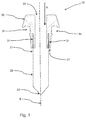
- FIG. 1 shows a cross-sectional view of a bag filter arrangement 10 in accordance with an exemplary embodiment.
- the bag filter arrangement 10 comprises a bag filter 20 and a bag filter seal 30.
- the bag filter seal has a center axis B.
- the bag filter 20 and bag filter seal 30 extends in a radial direction from the center axis B.
- the bag filter seal 30 typically extends further in a radial direction than the bag filter 20. Whereas the bag filter typically extends further in an axial direction along the center axis B than the bag filter seal 30.
- the bag filter 20 has an open end portion 21 and a closed end portion 22 opposite the open end portion 21.
- the closed end portion 22 may be closed by stichting or by using an adhesive.
- the bag filter 20 may comprise a PTFE membrane.
- the bag filter 20 may be made of polyester with or without a PTFE membrane.
- the bag filter 20 may be made of any other known bag filter materials.
- the length of the bag filter 20, seen as the vertical direction in figure 1 may be in the range of 500 mm to 1500 mm.
- the bag filter seal 30 comprises a recess 31 for receiving the open end portion 21 of the bag filter.
- the recess 31 is arranged on a bag filter facing surface 31' of the bag filter seal 30.
- the open end portion 21 may be attached in the recess 31 by either a row of stitches or by using an adhesive. Alternatively, both stitches and an adhesive may be used.
- the row of stitches may be a row of stitches around the circumference of the bag filter seal 30. In exemplary embodiments, at least two rows of stitches may be used. When using more than one row of stitches, the rows of stitches are preferably spaced apart.
- the bag filter seal 30 may be made of silicone, PVC, or rubber.
- the length of the closed end portion 21 which is inserted in the recess 31 may be in the range of 10 mm to 40 mm.
- the bag filter seal 30 further comprises an opening 33 in the top of the bag filter seal which is fluidly connected to the open end 21 of the bag filter 20.
- a powder product may be introduced into the bag filter 20 be being transported through the bag filter seal via the opening into the bag filter 20 in the direction indicated by the arrow A in figure 1 .
- the width e.g. the diameter if the opening 33 is circular, may be in the range of 20 mm to 40 mm.
- the width of the elongated opening 33 discussed with reference to figure 3b may also be in the range of 20 mm to 40 mm.
- the bag filter seal 30 further comprises a sealing portion 34.
- the sealing portion is arranged on the outside of the bag filter seal 30.
- the sealing portion 34 is the portion of the bag filter seal 30 which, in use, seals the bag filter arrangement 10 against the bag filter holder (not shown) such that a powder product is prevented from bypassing the bag filter arrangement 10.
- FIG 2 shows an enlarged view the bag filter seal 30.
- the bag filter seal 30 has an inner surface 35 and an outer surface 36. Note that the path from where the opening begins, marked by 33' in figure 2 , is shorter along the inner surface 35 than along the outer surface 36. This is because the outside, e.g. the outer surface 36, of the bag filter seal 30 comprises a number of features for further improving the sealing effect between the bag filter seal 30 and a bag filter holder (not shown).
- the outer surface 36 of the bag filter seal 30 comprises a first sealing protrusion 37.
- the first sealing protrusion 37 may be, and as shown in figure 2 , arranged at the same height, being the vertical direction in figure 2 , as the end of the recess 31. Thereby, the stiffness of the bag filter seal 30 may be increased in proximity of the end of the recess and the first sealing protrusion 37.
- the first sealing protrusion 37 may protrude substantially in a radial direction from the central axis B of the bag filter arrangement 10.
- the outer surface 36 of the bag filter seal 30 further comprises a second sealing protrusion 38.
- the second sealing protrusion 38 is arranged spaced apart from the first sealing protrusion 37.
- the second sealing protrusion 38 may protrude substantially in an axial direction of the central axis B. In other words, the second sealing protrusion 38 may extend downwards as seen in figure 2 .
- the outer surface 36 of the bag filter seal 30 further comprises a nook 39.
- the nook 39 is arranged between and spaced apart from the first and second sealing protrusions 37, 38.
- the nook 39 may also be construed as a corner located radially inwards, as seen from the central axis B, from the second sealing protrusion, and located axially upwards along the central axis B as seen in figure 2 .
- the first sealing protrusion 37, the second sealing protrusion 38, and the nook 39 may be understood as the sealing portion 34 of the bag filter seal 30 which is arranged to seal against a bag filter holder (not shown).
- the sealing portion 34 may be arranged to snap lock, or at least improve the attached to the bag filter holder by being flexible and resilient.
- the bag filter seal 30 may alternatively be described as having a top portion 30a and a bottom portion 30b.
- the top portion has a greater radial extension than the bottom portion 30b.
- the bottom portion 30b comprises the recess 31 and the first sealing protrusion 37.
- the bottom portion 30b at least partly encompasses the recess 31.
- the top portion 30a comprises the second sealing protrusion 38.
- the nook 39 is arranged between the top 30a and the bottom portion 30b.
- FIG 3a shows a perspective view of a round bag filter arrangement 110 according one embodiment.
- the round bag filter arrangment 110 comprises a bag filter 20 which has been inserted into a recess of the bag filter seal 30 and attached.
- the bag filter 20 and bag filter seal 30 are the same elements as described above in conjunction with figure 1 and 2 .
- a round bag filter arrangement 110 may typically only mounted vertically.
- FIG 3b shows a perspective view of an elongated flat bag filter arrangement 210 according one embodiment.
- the flat bag filter arrangement 210 has an elongated cross section perpendicular to the direction of the center axis B,
- the elongated flat bag filter arrangement 210 comprises a bag filter 20 which has been inserted into a recess of the bag filter seal 30 and attached.
- the bag filter 20 and bag filter seal 30 are the same elements as described above in conjunction with figure 1 and 2 .
- An elongated flat bag filter arrangement as shown in figure 3b may typically be mounted both vertically and horizontally. In order to mount the bag filter arrangement 210 horizontally, a rigid support structure may be inserted into the bag filter 20 through the opening in the bag bag filter seal 30.
- bag filter or bag filter seal may be made of other known materials.
Landscapes
- Chemical & Material Sciences (AREA)
- Chemical Kinetics & Catalysis (AREA)
- Packages (AREA)
- Bag Frames (AREA)
Abstract
Description
- The invention is related to
Swedish patent application no. 1551260-1, filed on 1 October 2015 - The present invention relates to a bag filter arrangement for being arranged in a bag filter holder.
- In the food, pharmaceutical and chemical industry, dried and powderized products or intermediate powderized products need to be separated from other undesired components before being packaged or delivered to further processes downstream. A powderized product or intermediate powderized product may henceforth be known as powder product. A known method is to use bag filter downstream of a silo or a hopper which hold and/or store the powder product, and filter the powder product using the bag filter. The powder product is thus fed into the bag filter which is made of different types of material and pore sizes for retaining the desired powder product. The undesired components are thus allowed to pass through the bag filter. The undesired component may be air, i.e. the bag filter may be arranged for separating air and the powder products. The powder product may be fed through the bag filter at high speed utilizing overpressure on the upstream side of the bag filter, or by utilizing a vacuum on the downstream side of the bag filter. Alternatively, the bag filter may be configured to allow the desired powder product to pass the bag filter, while retaining the undesired components. In either case, it is important to seal the edges of the bag filter to a bag filter e.g. the silo or hopper in order to prevent the powder product or undesired components from bypassing the bag filter. This is typically solved using some sort of seal between the bag filter and the bag filter holder.
- The seal may be moulded, or use felt or other materials for sealing against a bag filter holder. However, the mentioned options may not provide sufficient attachment to the bag filter itself, or may not be able to combine with certain materials used for the bag filters.
- There is thus a need for improving the state of the art to provide a bag filter arrangement which at least partly solves these problems.
- It is an object to improve the current state of the art, to solve at least some of the above problems. These and other objects are achieved by a bag filter arrangement.
- According to a first aspect a bag filter arrangement for being arranged in a bag filter holder is provided. The bag filter arrangement comprises: a bag filter having an end portion encompassing an open end of the bag filter; a bag filter seal for sealing against the bag filter holder, the bag filter seal being arranged to hold the bag filter, the bag filter seal comprising a bag filter facing surface; and wherein the bag filter seal comprises a recess on the bag filter facing surface, the recess being arranged to receive the open end portion of the bag filter.
- The bag filter arrangement is based on the realization that by providing a recess on a bag filter facing surface, which recess is arranged to receive the open end portion of the bag filter. An improved attachment between the bag filter seal and bag filter may be provided. Further, the bag filter may be attached to the bag filter seal after the manufacturing of the bag filter seal, which enables the bag filter seal and the bag filter to comprise material which were not able to be combine previously. The bag filter arrangement provides an improved seal between the bag filter and the bag filter holder. Further, a bag filter arrangement as described herein may be manufactured at a low cost.
- A bag filter holder may be understood as a silo or hopper containing the powder product to be filtered by the bag filter. The bag filter holder may comprises a plate having a hole or opening the general shape of the bag filter seal.
- In at least one exemplary embodiment, the bag filter seal comprises an opening, the opening being fluidly connected to an inside of the bag filter. The opening is facing the open end of the bag filter. The opening enables powder to be filtered to enter the bag filter via the opening in the seal.
- In at least one exemplary embodiment, the bag filter seal comprises an inner surface extending from the opening to an inside of the bag filter, and wherein the bag filter seal comprises an outer surface extending from the opening to an outside of the bag filter. The shortest path along the inner surface to the bag filter may be shorter than the shortest path along the outer surface to the bag filter. The outer surface may at least partly be facing away from the inside of the bag filter. The inner surface may at least partly be facing an inside of the bag filter.
- In at least one exemplary embodiment, the outer surface comprises a sealing protrusion arranged to seal against the bag filter holder. In at least one exemplary embodiment, the sealing protrusion is a first sealing protrusion and wherein the outer surface further comprises a second sealing protrusion arranged to seal against the bag filter holder. Sealing protrusion(s) may improve the sealing between the bag filter seal and the bag filter holder.
- In at least one exemplary embodiment, an end portion of the recess is located in proximity second protrusion. For example, the second sealing protrusion may be arranged radially outwardly of the end portion recess. This may provide an increased stiffness of the seal in the proximity of the end portion of the recess and the second sealing protrusion.
- In at least one exemplary embodiment, bag filter seal further comprises a nook arranged between the first and the second sealing protrusions. The nook may be construed as a corner, or a concave surface between the first and second sealing protrusions.
- In at least one exemplary embodiment, the first sealing protrusion, the nook, and the second sealing protrusion together forms a sealing portion of the bag filter seal, the sealing portion being arranged to seal against the bag filter holder. The sealing portion should the be understood to be arranged to be a receiving portion for an end portion of the bag filter holder which mates with the sealing portion. The first sealing protrusion, the nook, and the second sealing protrusion may provide a snap-lock such that the first and second sealing protrusion snap over edges of an end portion of the bag filter holder.
- In at least one exemplary embodiment, the bag filter seal is made of at least one of the following materials: Silicone, PVC (polyvinyl chloride), Rubber. Compared to the prior art which did not provide a freedom of choice in the seal materials, the above materials are more compatible with the powderized food product which may be used with the bag filter. The bag filter seal may be made using the techniques of vulcanisation or extrusion.
- In at least one exemplary embodiment, the bag filter comprises a PTFE (polytetrafluoroethylene) membrane, or polyester with or without a PTFE membrane. The bag filter arrangement enables the use of PTFE membranes for the bag filters, and the use of polyester with or without PTFE membranes.
- In at least one exemplary embodiment, wherein, in the recess, the end portion of the bag filter is attached to the bag filter seal by at least one row of stitches or adhesive means. The bag filter arrangement, due to the materials which may be used, enables the use of at least one row of stitches to attach the bag filter to the bag filter seal. The row of stitches should be interpreted as a row of stitches around the circumference of the seal, which thus attaches the bag filter in the recess. More than one row of stitches may be used, such as two rows of stitches. The adhesive may be any known and suitable adhesive.
- In at least one exemplary embodiment, the bag filter seal extends at least in a radial direction from a center axis of the bag filter arrangement. A central axis of the bag filter arrangement may be understood as a central axis of the bag filter, which passes through the opening of the bag ftiler seal.
- In at least one exemplary embodiment, the seal comprises a top portion and a bottom portion, the top portion having a radial extension greater than a radial extension of the bottom portion, and wherein the bottom portion at least partly encompasses the recess. The top portion may be construed as a support portion which, in use, rests on, and is thus supported by, the bag filter holder. The first sealing protrusion may be positioned on the top portion, the nook may be positioned between the top and bottom portions, and the second sealing protrusion may be positioned on the bottom portion facing radially outwards.
- Generally, all terms used in the claims are to be interpreted according to their ordinary meaning in the technical field, unless explicitly defined otherwise herein. All references to "a/an/the [element, device, component, means, step, etc.]" are to be interpreted openly as referring to at least one instance of said element, device, component, means, step, etc., unless explicitly stated otherwise.
- The above objects, as well as additional objects, features and advantages of the bag filter arrangement, will be more fully appreciated by reference to the following illustrative and non-limiting detailed description of preferred embodiments of the present invention, when taken in conjunction with the accompanying drawings, wherein:
-
Figure 1 is a cross-sectional view of a bag filter arrangement in accordance with an exemplary embodiment; -
Figure 2 is a cross-sectional view of a bag filter arrangement in accordance with an exemplary embodiment; -
Figure 3a is a perspective view of an exemplary embodiment. -
Figure 3b is a side view of an exemplary embodiment. - In the present detailed description, embodiments of a bag filter arrangement are mainly discussed with reference to views only showing components and portions being relevant in relation to various embodimentsof the bag filter arrangement. It should be noted that this by no means limits the scope of the bag filter arrangment, which is also applicable in other circumstances for instance with other types or variants of bag filter arrangements and processes than the embodiments shown in the appended drawings. Further, that specific features are mentioned in connection to an embodiment of the bag filter arrangement does not mean that those components cannot be used to an advantage together with other embodiments of the bag filter arrangement.
- The bag filter arrangement is suitable for being installed in an industrial food production facility, or pharmaceutical production facility, or chemical production facility, for filtering powder products. When a powder product is transported through the bag filter seal, and bag filter, undesired particles with a small size are allowed to pass the bag filter. The bag filter thus collects the desired powder products. Another mode of operation is of course that the powder product is allowed to pass through the bag filter, the bag filter being configured to allow the powder food product to pass through, and the bag filter collects the undesired particles. The powder product may be fed using pneumatic means and possible an overpressure, or by utilizing an under pressure, e.g. partial vacuum such as less than 1 kilo Pascal, on the downstream side of the bag filter arrangement. The powder product is thus filtered and may be transferred to further processes downstream such as different treatments and/or packaging. The bag filter arranged may be used for either a round, e.g. circular bag filter arrangement or an elongated, e.g. a flattened, bag filter arrangement. An embodiment of a round
bag filter arrangement 30 is shown infigure 3a , and an elongated bag filter arrangement 40 is shown infigure 3b . -
Figure 1 shows a cross-sectional view of abag filter arrangement 10 in accordance with an exemplary embodiment. Thebag filter arrangement 10 comprises abag filter 20 and abag filter seal 30. The bag filter seal has a center axis B. Thebag filter 20 andbag filter seal 30 extends in a radial direction from the center axis B. Thebag filter seal 30 typically extends further in a radial direction than thebag filter 20. Whereas the bag filter typically extends further in an axial direction along the center axis B than thebag filter seal 30. - The
bag filter 20 has anopen end portion 21 and aclosed end portion 22 opposite theopen end portion 21. Theclosed end portion 22 may be closed by stichting or by using an adhesive. Thebag filter 20 may comprise a PTFE membrane. For example, thebag filter 20 may be made of polyester with or without a PTFE membrane. Thebag filter 20 may be made of any other known bag filter materials. The length of thebag filter 20, seen as the vertical direction infigure 1 , may be in the range of 500 mm to 1500 mm. - The
bag filter seal 30 comprises arecess 31 for receiving theopen end portion 21 of the bag filter. Therecess 31 is arranged on a bag filter facing surface 31' of thebag filter seal 30. Theopen end portion 21 may be attached in therecess 31 by either a row of stitches or by using an adhesive. Alternatively, both stitches and an adhesive may be used. The row of stitches may be a row of stitches around the circumference of thebag filter seal 30. In exemplary embodiments, at least two rows of stitches may be used. When using more than one row of stitches, the rows of stitches are preferably spaced apart. Thebag filter seal 30 may be made of silicone, PVC, or rubber. The length of theclosed end portion 21 which is inserted in therecess 31 may be in the range of 10 mm to 40 mm. - The
bag filter seal 30 further comprises anopening 33 in the top of the bag filter seal which is fluidly connected to theopen end 21 of thebag filter 20. A powder product may be introduced into thebag filter 20 be being transported through the bag filter seal via the opening into thebag filter 20 in the direction indicated by the arrow A infigure 1 . The width, e.g. the diameter if theopening 33 is circular, may be in the range of 20 mm to 40 mm. The width of theelongated opening 33 discussed with reference tofigure 3b may also be in the range of 20 mm to 40 mm.Thebag filter seal 30 further comprises a sealingportion 34. The sealing portion is arranged on the outside of thebag filter seal 30. The sealingportion 34 is the portion of thebag filter seal 30 which, in use, seals thebag filter arrangement 10 against the bag filter holder (not shown) such that a powder product is prevented from bypassing thebag filter arrangement 10. -
Figure 2 shows an enlarged view thebag filter seal 30. Thebag filter seal 30 has aninner surface 35 and anouter surface 36. Note that the path from where the opening begins, marked by 33' infigure 2 , is shorter along theinner surface 35 than along theouter surface 36. This is because the outside, e.g. theouter surface 36, of thebag filter seal 30 comprises a number of features for further improving the sealing effect between thebag filter seal 30 and a bag filter holder (not shown). - The
outer surface 36 of thebag filter seal 30 comprises a first sealing protrusion 37. The first sealing protrusion 37 may be, and as shown infigure 2 , arranged at the same height, being the vertical direction infigure 2 , as the end of therecess 31. Thereby, the stiffness of thebag filter seal 30 may be increased in proximity of the end of the recess and the first sealing protrusion 37. The first sealing protrusion 37 may protrude substantially in a radial direction from the central axis B of thebag filter arrangement 10. - The
outer surface 36 of thebag filter seal 30 further comprises a second sealing protrusion 38. The second sealing protrusion 38 is arranged spaced apart from the first sealing protrusion 37. The second sealing protrusion 38 may protrude substantially in an axial direction of the central axis B. In other words, the second sealing protrusion 38 may extend downwards as seen infigure 2 . - The
outer surface 36 of thebag filter seal 30 further comprises anook 39. Thenook 39 is arranged between and spaced apart from the first and second sealing protrusions 37, 38. Thenook 39 may also be construed as a corner located radially inwards, as seen from the central axis B, from the second sealing protrusion, and located axially upwards along the central axis B as seen infigure 2 . - The first sealing protrusion 37, the second sealing protrusion 38, and the
nook 39 may be understood as the sealingportion 34 of thebag filter seal 30 which is arranged to seal against a bag filter holder (not shown). The sealingportion 34 may be arranged to snap lock, or at least improve the attached to the bag filter holder by being flexible and resilient. - The
bag filter seal 30 may alternatively be described as having atop portion 30a and abottom portion 30b. The top portion has a greater radial extension than thebottom portion 30b. Thebottom portion 30b comprises therecess 31 and the first sealing protrusion 37. Thebottom portion 30b at least partly encompasses therecess 31. Thetop portion 30a comprises the second sealing protrusion 38. Thenook 39 is arranged between the top 30a and thebottom portion 30b. -
Figure 3a shows a perspective view of a roundbag filter arrangement 110 according one embodiment. The round bag filter arrangment 110 comprises abag filter 20 which has been inserted into a recess of thebag filter seal 30 and attached. Thebag filter 20 andbag filter seal 30 are the same elements as described above in conjunction withfigure 1 and2 . A roundbag filter arrangement 110 may typically only mounted vertically. -
Figure 3b shows a perspective view of an elongated flatbag filter arrangement 210 according one embodiment. The flatbag filter arrangement 210 has an elongated cross section perpendicular to the direction of the center axis B, The elongated flatbag filter arrangement 210 comprises abag filter 20 which has been inserted into a recess of thebag filter seal 30 and attached. Thebag filter 20 andbag filter seal 30 are the same elements as described above in conjunction withfigure 1 and2 . An elongated flat bag filter arrangement as shown infigure 3b may typically be mounted both vertically and horizontally. In order to mount thebag filter arrangement 210 horizontally, a rigid support structure may be inserted into thebag filter 20 through the opening in the bagbag filter seal 30. - It is of course understood that variations to the shown embodiment may be effected and still be within the scope of the invention described herein, for example the bag filter or bag filter seal may be made of other known materials.
- The skilled person realizes that a number of modifications of the embodiments described herein are possible without departing from the scope of the invention, which is defined in the appended claims.
Claims (12)
- A bag filter arrangement (10) for being arranged in a bag filter holder, said bag filter arrangement (10) comprises:a bag filter (20) having an end portion (21) encompassing an open end of the bag filter (20);a bag filter seal (30) for sealing against said bag filter holder, said bag filter seal (30) being arranged to hold said bag filter (20), said bag filter seal (30) comprising a bag filter facing surface (31'); andwherein said bag filter seal (30) comprises a recess (31) on said bag filter facing surface (31'), said recess (31) being arranged to receive said open end portion (21) of said bag filter (20).
- A bag filter arrangement (10) according to claim 1, wherein said bag filter seal (30) comprises an opening (33), said opening (33) being fluidly connected to an inside of said bag filter (20).
- A bag filter arrangement (10) according to claim 2, wherein said bag filter seal (30) comprises an inner surface extending from said opening to an inside of said bag filter, and wherein said bag filter seal (30) comprises an outer surface (36) extending from said opening (33) to an outside of said bag filter (20).
- A bag filter arrangement (10) according to claim 3, wherein said outer surface (36) comprises a sealing protrusion (37) arranged to seal against the bag filter holder.
- A bag filter arrangement (10) according to claim 4, wherein said sealing protrusion is a first sealing protrusion (37) and wherein said outer surface further comprises a second sealing protrusion (38) arranged to seal against the bag filter holder.
- A bag filter arrangement (10) according to claim 5, wherein said bag filter seal (30) further comprises a nook (39) arranged between said first and said second sealing protrusions.
- A bag filter arrangement (10) according to claim 6, wherein said first sealing protrusion (37), said nook(39), and said second sealing protrusion (38) together forms a sealing portion of said bag filter seal (30), said sealing portion being arranged to seal against the bag filter holder.
- A bag filter arrangement (10) according to any one of the preceding claims, wherein said bag filter seal (30) is made of at least one of the following materials: Silicone, PVC, or rubber.
- A bag filter arrangement (10) according to any one of the preceding claims, wherein said bag filter comprises a PTFE membrane, or polyester with or without a PTFE Membrane.
- A bag filter arrangement (10) according to any one of the preceding claims, wherein, in said recess, said end portion of said bag filter is attached to said bag filter seal (30) by at least one row of stitches or adhesive means.
- A bag filter arrangement (10) according to any one of the preceding claims, wherein said bag filter seal (30) extends at least in a radial direction from a center axis of the bag filter arrangement (10).
- A bag filter arrangement (10) according to claim 11, wherein said seal comprises a top portion and a bottom portion, said top portion having a radial extension greater than a radial extension of said bottom portion, and wherein said bottom portion at least partly encompasses said recess.
Applications Claiming Priority (1)
| Application Number | Priority Date | Filing Date | Title |
|---|---|---|---|
| SE1551260 | 2015-10-01 |
Publications (2)
| Publication Number | Publication Date |
|---|---|
| EP3150269A1 true EP3150269A1 (en) | 2017-04-05 |
| EP3150269B1 EP3150269B1 (en) | 2019-06-26 |
Family
ID=57044881
Family Applications (1)
| Application Number | Title | Priority Date | Filing Date |
|---|---|---|---|
| EP16191291.0A Active EP3150269B1 (en) | 2015-10-01 | 2016-09-29 | Bag filter arrangement and seal comprising a recess |
Country Status (2)
| Country | Link |
|---|---|
| US (1) | US10279297B2 (en) |
| EP (1) | EP3150269B1 (en) |
Cited By (3)
| Publication number | Priority date | Publication date | Assignee | Title |
|---|---|---|---|---|
| WO2023122106A1 (en) * | 2021-12-21 | 2023-06-29 | Donaldson Company, Inc. | Filter systems with filter bag assemblies including filter bags with radial seal gaskets |
| US11883763B2 (en) | 2019-09-13 | 2024-01-30 | Donaldson Company, Inc. | Air filter systems, filter bag assemblies, filter bags and methods |
| US12605664B2 (en) | 2021-03-16 | 2026-04-21 | Donaldson Company, Inc. | Foldable filter bags, filter bag support assemblies, and filter bag assemblies |
Families Citing this family (1)
| Publication number | Priority date | Publication date | Assignee | Title |
|---|---|---|---|---|
| KR102306389B1 (en) * | 2016-03-08 | 2021-09-30 | 케이앤드엔 엔지니어링, 인크. | Ultra-Pleated Vehicle Air Filters |
Citations (2)
| Publication number | Priority date | Publication date | Assignee | Title |
|---|---|---|---|---|
| US5045194A (en) * | 1990-04-02 | 1991-09-03 | Gaf Chemicals Corporation | Filter apparatus having a bag with handles |
| DE10223352A1 (en) * | 2002-05-25 | 2003-12-11 | Infiltec Gmbh | Sealing ring, for liquid filter bag, has upper flange for mounting at filter housing together with double-wall inner collar to take the inserted edge of bag with clip |
Family Cites Families (2)
| Publication number | Priority date | Publication date | Assignee | Title |
|---|---|---|---|---|
| WO1998009716A1 (en) | 1996-09-06 | 1998-03-12 | The Dow Chemical Company | Process for reducing dioxin and furan emissions in the stack gas from an incinerator |
| US5755962A (en) * | 1996-11-26 | 1998-05-26 | Isp Investments Inc. | Filter bag and process of manufacture |
-
2016
- 2016-09-29 EP EP16191291.0A patent/EP3150269B1/en active Active
- 2016-09-30 US US15/281,936 patent/US10279297B2/en active Active
Patent Citations (2)
| Publication number | Priority date | Publication date | Assignee | Title |
|---|---|---|---|---|
| US5045194A (en) * | 1990-04-02 | 1991-09-03 | Gaf Chemicals Corporation | Filter apparatus having a bag with handles |
| DE10223352A1 (en) * | 2002-05-25 | 2003-12-11 | Infiltec Gmbh | Sealing ring, for liquid filter bag, has upper flange for mounting at filter housing together with double-wall inner collar to take the inserted edge of bag with clip |
Cited By (4)
| Publication number | Priority date | Publication date | Assignee | Title |
|---|---|---|---|---|
| US11883763B2 (en) | 2019-09-13 | 2024-01-30 | Donaldson Company, Inc. | Air filter systems, filter bag assemblies, filter bags and methods |
| US12465881B2 (en) | 2019-09-13 | 2025-11-11 | Donaldson Company, Inc. | Air filter systems, filter bag assemblies, filter bags and methods |
| US12605664B2 (en) | 2021-03-16 | 2026-04-21 | Donaldson Company, Inc. | Foldable filter bags, filter bag support assemblies, and filter bag assemblies |
| WO2023122106A1 (en) * | 2021-12-21 | 2023-06-29 | Donaldson Company, Inc. | Filter systems with filter bag assemblies including filter bags with radial seal gaskets |
Also Published As
| Publication number | Publication date |
|---|---|
| NZ724569A (en) | 2024-04-26 |
| EP3150269B1 (en) | 2019-06-26 |
| US10279297B2 (en) | 2019-05-07 |
| US20170095763A1 (en) | 2017-04-06 |
Similar Documents
| Publication | Publication Date | Title |
|---|---|---|
| EP3150269B1 (en) | Bag filter arrangement and seal comprising a recess | |
| US9120059B2 (en) | Ventilation unit | |
| US20210396323A1 (en) | Ventilation component | |
| CN109417856B (en) | Ventilation Department | |
| JP2023179453A (en) | ventilation parts | |
| US10940095B2 (en) | Vented bottle | |
| EP2557356B1 (en) | Ventilation member | |
| WO2019006079A3 (en) | Filter-gasket assembly with seal and placement indicator for sterilization rigid container | |
| CN110574503B (en) | vent parts | |
| US20160303501A1 (en) | End cap and air filter incorporating same | |
| CN104080290A (en) | Ventilation member | |
| JP7286789B2 (en) | ventilation parts | |
| JP7723050B2 (en) | Ventilation parts | |
| CA2980027C (en) | Fitment splash guard | |
| US20120324845A1 (en) | Filter assembly for use in a baghouse | |
| KR101854780B1 (en) | Vacuum pipe support apparatus for semiconductor and display manufacturing device | |
| CN215196008U (en) | Filtering structure of vacuum feeding machine | |
| US20120324844A1 (en) | Filter assembly for use in a baghouse | |
| CN109985524B (en) | Filter and method for manufacturing the same | |
| CN111824598A (en) | Filter for a ventilation opening of a container | |
| US20230272326A1 (en) | Methods and devices for aseptic dry transfer | |
| US20130153481A1 (en) | Filter support member | |
| CH702936A2 (en) | High-sensitivity valve for balancing pressure differences between the inside and outside of rigid or flexible containers and for preventing return in pneumatic and hydraulic circuits comprises a ball with elastic arms | |
| WO2017099249A1 (en) | Flexible container | |
| CN203392189U (en) | Dampproof bottle |
Legal Events
| Date | Code | Title | Description |
|---|---|---|---|
| PUAI | Public reference made under article 153(3) epc to a published international application that has entered the european phase |
Free format text: ORIGINAL CODE: 0009012 |
|
| STAA | Information on the status of an ep patent application or granted ep patent |
Free format text: STATUS: THE APPLICATION HAS BEEN PUBLISHED |
|
| AK | Designated contracting states |
Kind code of ref document: A1 Designated state(s): AL AT BE BG CH CY CZ DE DK EE ES FI FR GB GR HR HU IE IS IT LI LT LU LV MC MK MT NL NO PL PT RO RS SE SI SK SM TR |
|
| AX | Request for extension of the european patent |
Extension state: BA ME |
|
| STAA | Information on the status of an ep patent application or granted ep patent |
Free format text: STATUS: REQUEST FOR EXAMINATION WAS MADE |
|
| 17P | Request for examination filed |
Effective date: 20171005 |
|
| RBV | Designated contracting states (corrected) |
Designated state(s): AL AT BE BG CH CY CZ DE DK EE ES FI FR GB GR HR HU IE IS IT LI LT LU LV MC MK MT NL NO PL PT RO RS SE SI SK SM TR |
|
| STAA | Information on the status of an ep patent application or granted ep patent |
Free format text: STATUS: EXAMINATION IS IN PROGRESS |
|
| 17Q | First examination report despatched |
Effective date: 20180803 |
|
| GRAP | Despatch of communication of intention to grant a patent |
Free format text: ORIGINAL CODE: EPIDOSNIGR1 |
|
| STAA | Information on the status of an ep patent application or granted ep patent |
Free format text: STATUS: GRANT OF PATENT IS INTENDED |
|
| INTG | Intention to grant announced |
Effective date: 20190123 |
|
| GRAS | Grant fee paid |
Free format text: ORIGINAL CODE: EPIDOSNIGR3 |
|
| GRAA | (expected) grant |
Free format text: ORIGINAL CODE: 0009210 |
|
| STAA | Information on the status of an ep patent application or granted ep patent |
Free format text: STATUS: THE PATENT HAS BEEN GRANTED |
|
| AK | Designated contracting states |
Kind code of ref document: B1 Designated state(s): AL AT BE BG CH CY CZ DE DK EE ES FI FR GB GR HR HU IE IS IT LI LT LU LV MC MK MT NL NO PL PT RO RS SE SI SK SM TR |
|
| REG | Reference to a national code |
Ref country code: GB Ref legal event code: FG4D |
|
| REG | Reference to a national code |
Ref country code: CH Ref legal event code: EP |
|
| REG | Reference to a national code |
Ref country code: AT Ref legal event code: REF Ref document number: 1147652 Country of ref document: AT Kind code of ref document: T Effective date: 20190715 |
|
| REG | Reference to a national code |
Ref country code: DE Ref legal event code: R096 Ref document number: 602016015829 Country of ref document: DE |
|
| REG | Reference to a national code |
Ref country code: IE Ref legal event code: FG4D |
|
| REG | Reference to a national code |
Ref country code: NL Ref legal event code: MP Effective date: 20190626 |
|
| PG25 | Lapsed in a contracting state [announced via postgrant information from national office to epo] |
Ref country code: NO Free format text: LAPSE BECAUSE OF FAILURE TO SUBMIT A TRANSLATION OF THE DESCRIPTION OR TO PAY THE FEE WITHIN THE PRESCRIBED TIME-LIMIT Effective date: 20190926 Ref country code: HR Free format text: LAPSE BECAUSE OF FAILURE TO SUBMIT A TRANSLATION OF THE DESCRIPTION OR TO PAY THE FEE WITHIN THE PRESCRIBED TIME-LIMIT Effective date: 20190626 Ref country code: SE Free format text: LAPSE BECAUSE OF FAILURE TO SUBMIT A TRANSLATION OF THE DESCRIPTION OR TO PAY THE FEE WITHIN THE PRESCRIBED TIME-LIMIT Effective date: 20190626 Ref country code: FI Free format text: LAPSE BECAUSE OF FAILURE TO SUBMIT A TRANSLATION OF THE DESCRIPTION OR TO PAY THE FEE WITHIN THE PRESCRIBED TIME-LIMIT Effective date: 20190626 Ref country code: AL Free format text: LAPSE BECAUSE OF FAILURE TO SUBMIT A TRANSLATION OF THE DESCRIPTION OR TO PAY THE FEE WITHIN THE PRESCRIBED TIME-LIMIT Effective date: 20190626 Ref country code: LT Free format text: LAPSE BECAUSE OF FAILURE TO SUBMIT A TRANSLATION OF THE DESCRIPTION OR TO PAY THE FEE WITHIN THE PRESCRIBED TIME-LIMIT Effective date: 20190626 |
|
| REG | Reference to a national code |
Ref country code: LT Ref legal event code: MG4D |
|
| PG25 | Lapsed in a contracting state [announced via postgrant information from national office to epo] |
Ref country code: BG Free format text: LAPSE BECAUSE OF FAILURE TO SUBMIT A TRANSLATION OF THE DESCRIPTION OR TO PAY THE FEE WITHIN THE PRESCRIBED TIME-LIMIT Effective date: 20190926 Ref country code: LV Free format text: LAPSE BECAUSE OF FAILURE TO SUBMIT A TRANSLATION OF THE DESCRIPTION OR TO PAY THE FEE WITHIN THE PRESCRIBED TIME-LIMIT Effective date: 20190626 Ref country code: RS Free format text: LAPSE BECAUSE OF FAILURE TO SUBMIT A TRANSLATION OF THE DESCRIPTION OR TO PAY THE FEE WITHIN THE PRESCRIBED TIME-LIMIT Effective date: 20190626 Ref country code: GR Free format text: LAPSE BECAUSE OF FAILURE TO SUBMIT A TRANSLATION OF THE DESCRIPTION OR TO PAY THE FEE WITHIN THE PRESCRIBED TIME-LIMIT Effective date: 20190927 |
|
| REG | Reference to a national code |
Ref country code: AT Ref legal event code: MK05 Ref document number: 1147652 Country of ref document: AT Kind code of ref document: T Effective date: 20190626 |
|
| PG25 | Lapsed in a contracting state [announced via postgrant information from national office to epo] |
Ref country code: SK Free format text: LAPSE BECAUSE OF FAILURE TO SUBMIT A TRANSLATION OF THE DESCRIPTION OR TO PAY THE FEE WITHIN THE PRESCRIBED TIME-LIMIT Effective date: 20190626 Ref country code: RO Free format text: LAPSE BECAUSE OF FAILURE TO SUBMIT A TRANSLATION OF THE DESCRIPTION OR TO PAY THE FEE WITHIN THE PRESCRIBED TIME-LIMIT Effective date: 20190626 Ref country code: AT Free format text: LAPSE BECAUSE OF FAILURE TO SUBMIT A TRANSLATION OF THE DESCRIPTION OR TO PAY THE FEE WITHIN THE PRESCRIBED TIME-LIMIT Effective date: 20190626 Ref country code: EE Free format text: LAPSE BECAUSE OF FAILURE TO SUBMIT A TRANSLATION OF THE DESCRIPTION OR TO PAY THE FEE WITHIN THE PRESCRIBED TIME-LIMIT Effective date: 20190626 Ref country code: NL Free format text: LAPSE BECAUSE OF FAILURE TO SUBMIT A TRANSLATION OF THE DESCRIPTION OR TO PAY THE FEE WITHIN THE PRESCRIBED TIME-LIMIT Effective date: 20190626 Ref country code: CZ Free format text: LAPSE BECAUSE OF FAILURE TO SUBMIT A TRANSLATION OF THE DESCRIPTION OR TO PAY THE FEE WITHIN THE PRESCRIBED TIME-LIMIT Effective date: 20190626 Ref country code: PT Free format text: LAPSE BECAUSE OF FAILURE TO SUBMIT A TRANSLATION OF THE DESCRIPTION OR TO PAY THE FEE WITHIN THE PRESCRIBED TIME-LIMIT Effective date: 20191028 |
|
| PG25 | Lapsed in a contracting state [announced via postgrant information from national office to epo] |
Ref country code: SM Free format text: LAPSE BECAUSE OF FAILURE TO SUBMIT A TRANSLATION OF THE DESCRIPTION OR TO PAY THE FEE WITHIN THE PRESCRIBED TIME-LIMIT Effective date: 20190626 Ref country code: IS Free format text: LAPSE BECAUSE OF FAILURE TO SUBMIT A TRANSLATION OF THE DESCRIPTION OR TO PAY THE FEE WITHIN THE PRESCRIBED TIME-LIMIT Effective date: 20191026 Ref country code: IT Free format text: LAPSE BECAUSE OF FAILURE TO SUBMIT A TRANSLATION OF THE DESCRIPTION OR TO PAY THE FEE WITHIN THE PRESCRIBED TIME-LIMIT Effective date: 20190626 Ref country code: ES Free format text: LAPSE BECAUSE OF FAILURE TO SUBMIT A TRANSLATION OF THE DESCRIPTION OR TO PAY THE FEE WITHIN THE PRESCRIBED TIME-LIMIT Effective date: 20190626 |
|
| PG25 | Lapsed in a contracting state [announced via postgrant information from national office to epo] |
Ref country code: TR Free format text: LAPSE BECAUSE OF FAILURE TO SUBMIT A TRANSLATION OF THE DESCRIPTION OR TO PAY THE FEE WITHIN THE PRESCRIBED TIME-LIMIT Effective date: 20190626 |
|
| PG25 | Lapsed in a contracting state [announced via postgrant information from national office to epo] |
Ref country code: PL Free format text: LAPSE BECAUSE OF FAILURE TO SUBMIT A TRANSLATION OF THE DESCRIPTION OR TO PAY THE FEE WITHIN THE PRESCRIBED TIME-LIMIT Effective date: 20190626 Ref country code: DK Free format text: LAPSE BECAUSE OF FAILURE TO SUBMIT A TRANSLATION OF THE DESCRIPTION OR TO PAY THE FEE WITHIN THE PRESCRIBED TIME-LIMIT Effective date: 20190626 |
|
| PG25 | Lapsed in a contracting state [announced via postgrant information from national office to epo] |
Ref country code: IS Free format text: LAPSE BECAUSE OF FAILURE TO SUBMIT A TRANSLATION OF THE DESCRIPTION OR TO PAY THE FEE WITHIN THE PRESCRIBED TIME-LIMIT Effective date: 20200224 Ref country code: MC Free format text: LAPSE BECAUSE OF FAILURE TO SUBMIT A TRANSLATION OF THE DESCRIPTION OR TO PAY THE FEE WITHIN THE PRESCRIBED TIME-LIMIT Effective date: 20190626 |
|
| REG | Reference to a national code |
Ref country code: CH Ref legal event code: PL |
|
| REG | Reference to a national code |
Ref country code: DE Ref legal event code: R097 Ref document number: 602016015829 Country of ref document: DE |
|
| PLBE | No opposition filed within time limit |
Free format text: ORIGINAL CODE: 0009261 |
|
| STAA | Information on the status of an ep patent application or granted ep patent |
Free format text: STATUS: NO OPPOSITION FILED WITHIN TIME LIMIT |
|
| PG2D | Information on lapse in contracting state deleted |
Ref country code: IS |
|
| PG25 | Lapsed in a contracting state [announced via postgrant information from national office to epo] |
Ref country code: IE Free format text: LAPSE BECAUSE OF NON-PAYMENT OF DUE FEES Effective date: 20190929 Ref country code: LU Free format text: LAPSE BECAUSE OF NON-PAYMENT OF DUE FEES Effective date: 20190929 Ref country code: LI Free format text: LAPSE BECAUSE OF NON-PAYMENT OF DUE FEES Effective date: 20190930 Ref country code: CH Free format text: LAPSE BECAUSE OF NON-PAYMENT OF DUE FEES Effective date: 20190930 |
|
| 26N | No opposition filed |
Effective date: 20200603 |
|
| REG | Reference to a national code |
Ref country code: BE Ref legal event code: MM Effective date: 20190930 |
|
| PG25 | Lapsed in a contracting state [announced via postgrant information from national office to epo] |
Ref country code: SI Free format text: LAPSE BECAUSE OF FAILURE TO SUBMIT A TRANSLATION OF THE DESCRIPTION OR TO PAY THE FEE WITHIN THE PRESCRIBED TIME-LIMIT Effective date: 20190626 Ref country code: BE Free format text: LAPSE BECAUSE OF NON-PAYMENT OF DUE FEES Effective date: 20190930 |
|
| GBPC | Gb: european patent ceased through non-payment of renewal fee |
Effective date: 20200929 |
|
| PG25 | Lapsed in a contracting state [announced via postgrant information from national office to epo] |
Ref country code: CY Free format text: LAPSE BECAUSE OF FAILURE TO SUBMIT A TRANSLATION OF THE DESCRIPTION OR TO PAY THE FEE WITHIN THE PRESCRIBED TIME-LIMIT Effective date: 20190626 |
|
| PG25 | Lapsed in a contracting state [announced via postgrant information from national office to epo] |
Ref country code: MT Free format text: LAPSE BECAUSE OF FAILURE TO SUBMIT A TRANSLATION OF THE DESCRIPTION OR TO PAY THE FEE WITHIN THE PRESCRIBED TIME-LIMIT Effective date: 20190626 Ref country code: HU Free format text: LAPSE BECAUSE OF FAILURE TO SUBMIT A TRANSLATION OF THE DESCRIPTION OR TO PAY THE FEE WITHIN THE PRESCRIBED TIME-LIMIT; INVALID AB INITIO Effective date: 20160929 |
|
| PG25 | Lapsed in a contracting state [announced via postgrant information from national office to epo] |
Ref country code: GB Free format text: LAPSE BECAUSE OF NON-PAYMENT OF DUE FEES Effective date: 20200929 |
|
| PG25 | Lapsed in a contracting state [announced via postgrant information from national office to epo] |
Ref country code: MK Free format text: LAPSE BECAUSE OF FAILURE TO SUBMIT A TRANSLATION OF THE DESCRIPTION OR TO PAY THE FEE WITHIN THE PRESCRIBED TIME-LIMIT Effective date: 20190626 |
|
| P01 | Opt-out of the competence of the unified patent court (upc) registered |
Effective date: 20230426 |
|
| PGFP | Annual fee paid to national office [announced via postgrant information from national office to epo] |
Ref country code: DE Payment date: 20250926 Year of fee payment: 10 |
|
| PGFP | Annual fee paid to national office [announced via postgrant information from national office to epo] |
Ref country code: FR Payment date: 20250925 Year of fee payment: 10 |