EP3149260B1 - Fencing mesh and fence - Google Patents
Fencing mesh and fence Download PDFInfo
- Publication number
- EP3149260B1 EP3149260B1 EP15734725.3A EP15734725A EP3149260B1 EP 3149260 B1 EP3149260 B1 EP 3149260B1 EP 15734725 A EP15734725 A EP 15734725A EP 3149260 B1 EP3149260 B1 EP 3149260B1
- Authority
- EP
- European Patent Office
- Prior art keywords
- wires
- fencing mesh
- mesh
- fencing
- fence
- Prior art date
- Legal status (The legal status is an assumption and is not a legal conclusion. Google has not performed a legal analysis and makes no representation as to the accuracy of the status listed.)
- Active
Links
Images


Classifications
-
- E—FIXED CONSTRUCTIONS
- E04—BUILDING
- E04H—BUILDINGS OR LIKE STRUCTURES FOR PARTICULAR PURPOSES; SWIMMING OR SPLASH BATHS OR POOLS; MASTS; FENCING; TENTS OR CANOPIES, IN GENERAL
- E04H17/00—Fencing, e.g. fences, enclosures, corrals
- E04H17/14—Fences constructed of rigid elements, e.g. with additional wire fillings or with posts
- E04H17/16—Fences constructed of rigid elements, e.g. with additional wire fillings or with posts using prefabricated panel-like elements, e.g. wired frames
- E04H17/161—Fences constructed of rigid elements, e.g. with additional wire fillings or with posts using prefabricated panel-like elements, e.g. wired frames using wire panels
-
- F—MECHANICAL ENGINEERING; LIGHTING; HEATING; WEAPONS; BLASTING
- F41—WEAPONS
- F41H—ARMOUR; ARMOURED TURRETS; ARMOURED OR ARMED VEHICLES; MEANS OF ATTACK OR DEFENCE, e.g. CAMOUFLAGE, IN GENERAL
- F41H5/00—Armour; Armour plates
- F41H5/02—Plate construction
- F41H5/023—Armour plate, or auxiliary armour plate mounted at a distance of the main armour plate, having cavities at its outer impact surface, or holes, for deflecting the projectile
- F41H5/026—Slat armour; Nets
-
- E—FIXED CONSTRUCTIONS
- E04—BUILDING
- E04H—BUILDINGS OR LIKE STRUCTURES FOR PARTICULAR PURPOSES; SWIMMING OR SPLASH BATHS OR POOLS; MASTS; FENCING; TENTS OR CANOPIES, IN GENERAL
- E04H17/00—Fencing, e.g. fences, enclosures, corrals
- E04H17/02—Wire fencing, e.g. made of wire mesh
- E04H17/10—Wire fencing, e.g. made of wire mesh characterised by the way of connecting wire to posts; Droppers
- E04H17/12—Wire fencing, e.g. made of wire mesh characterised by the way of connecting wire to posts; Droppers the wire being placed in slots, grooves, or the like
-
- E—FIXED CONSTRUCTIONS
- E04—BUILDING
- E04H—BUILDINGS OR LIKE STRUCTURES FOR PARTICULAR PURPOSES; SWIMMING OR SPLASH BATHS OR POOLS; MASTS; FENCING; TENTS OR CANOPIES, IN GENERAL
- E04H17/00—Fencing, e.g. fences, enclosures, corrals
- E04H17/14—Fences constructed of rigid elements, e.g. with additional wire fillings or with posts
- E04H17/24—Connections for attaching additional wire to frames, posts or railings
-
- F—MECHANICAL ENGINEERING; LIGHTING; HEATING; WEAPONS; BLASTING
- F41—WEAPONS
- F41H—ARMOUR; ARMOURED TURRETS; ARMOURED OR ARMED VEHICLES; MEANS OF ATTACK OR DEFENCE, e.g. CAMOUFLAGE, IN GENERAL
- F41H5/00—Armour; Armour plates
- F41H5/013—Mounting or securing armour plates
Definitions
- the present invention relates to a fencing mesh for protecting an interior space from projectiles, comprising a first set of wires which are arranged essentially parallel with respect to each other and a second set of wires which are arranged essentially parallel with respect to each other and intersect the first set of wires, wherein the wires of the first set are connected to the wires of the second set at the locations where they intersect.
- the present invention relates to a fence comprising such a fencing mesh.
- the present invention also relates to a method for producing a specific embodiment of such a fencing mesh.
- a number of fence systems comprising fencing mesh and configured to be able to catch projectiles are already known on the market.
- the fencing mesh of these fence systems is typically a woven wire mesh which is sufficiently flexible to be able to absorb the impact of projectiles striking it.
- Such fence systems are described, for example, in WO 99/43894 A1 and WO 2005/120744 .
- Such fence systems are inter alia also used to construct screenings for potential targets of attackers in order to intercept projectiles, such as for example, rocket-launched grenades and to detonate these before the actual target. In this way, for example ships or chemical installations or drilling platforms, etc. are screened off from potential attacks.
- these fencing mesh panels can only span very small surface areas and also require sufficient external support. Therefore, these systems are not very suitable for screening off large surface areas in this way.
- WO 92/00496 and US 2010/0102166 describe fencing mesh panels for protecting an interior space from projectiles which comprise a first set of wires and a second set of wires, wherein the wires of the second set have a greater tensile strength than the wires of the first set. This makes it possible to protect larger surface areas from projectiles using such a fencing mesh.
- a fencing mesh By providing two types of wires, each having a different tensile strength, it is possible to construct a fencing mesh, in which the wires having a greater tensile strength provide the strength of the fencing mesh, so that less external support is required in order to construct a fence.
- the wires having a lower tensile strength in turn provide sufficient flexibility in the fencing mesh to be able to absorb the kinetic energy of the projectiles upon impact.
- the principal aim is to cause projectiles to explode before the fencing mesh. When projectiles explode, the damage to such a fencing mesh is relatively extensive.
- WO 03/101726 A1 concerns a reinforced composite panel.
- This panel comprises a sandwich structure, wherein a metal grid of rods serves as a reinforcement and does not form a fencing mesh to be used as such.
- EP 1712710 A1 describes a post and a welded mesh panel. Such a welded mesh panel is not suitable for protecting an interior space from projectiles.
- the object of the present invention is to provide a fencing mesh which also makes it possible to protect relatively large surface areas in a simple way to protect against projectiles, wherein this fencing mesh is only damaged to a minimal degree upon impact and a smaller distance is required between the fencing mesh and a potential target to be protected in the interior space.
- a fencing mesh comprising a first set of wires which are arranged essentially parallel with respect to each other and a second set of wires which are arranged essentially parallel with respect to each other and intersect the first set of wires, wherein the wires of the first set are connected to the wires of the second set at the locations where they intersect, wherein the wires of the second set have a greater tensile strength than the wires of the first set, and wherein the wires are welded to one another in order to connect them to each other.
- the wires having a lower tensile strength move apart sufficiently, so that a projectile can be caught between the wires and damaged.
- the wires having a greater tensile strength retain the structure of the fencing mesh as well as possible and are welded to the wires having a lower tensile strength in such a way that the projectile cannot pass through the fencing mesh. In this way, a projectile can become buried in the fencing mesh, thus reducing the functionality of such a projectile. According to the invention, it is thus no longer intended to cause a projectile to explode before the fence or behind the fence, but to limit its effect. As a result of the more limited impact and welding the wires together, the fencing mesh is only damaged to a limited degree upon detonation of the projectiles.
- welding' is to be interpreted broadly in the sense of any process or treatment, optionally with the addition of welding materials or bonding materials or products, and optionally accompanied by (local) heating of the parts to be connected, which results in a durable connection without external coupling means having a substantially mechanical connecting function.
- the wires of a fencing mesh according to the present invention may have various forms. Preferably, however, they have an essentially round cross section.
- the tensile strengths and diameters of the wires, as well as the intermediate distances between the wires are preferably chosen as a function of the expected projectiles which this fencing mesh serves to be able to catch.
- the wires of the first set preferably have a tensile strength of less than 550 MPa. Still more preferably, these wires have a tensile strength of more than 300 MPa. Furthermore, these wires of the first set preferably have a diameter of at most 3 mm.
- the wires of the second set preferably have a tensile strength of more than 550 MPa. Furthermore, these wires of the second set preferably have a diameter of at least 3 mm.
- the intermediate distance between the wires of the first set is preferably smaller than the intermediate distance between the wires of the second set. Still more preferably, this intermediate distance between the wires of the first set is preferably at least twice as small as the intermediate distance between the wires of the second set.
- the intermediate distance between the wires of the first set is preferably chosen to be between 15 mm and 35 mm and is preferably essentially 20 mm.
- the intermediate distance between the wires of the second set is preferably chosen to be between 30 mm and 70 mm and is preferably essentially 40 mm.
- the wires of a fencing mesh according to the present invention may furthermore be made of different kinds of materials.
- the wires of the second set are made of steel.
- the wires of the first set are preferably also made of steel. When steel wires are used as the wires in a fencing mesh according to the present invention, then these are preferably galvanized.
- the first set of wires and the second set of wires intersect essentially at right angles.
- the wires of the second set of a fencing mesh according to the present invention are furthermore preferably designed to extend essentially vertically in the fitted position of the fencing mesh.
- the wires of the first set are designed to extend essentially horizontally in the fitted position of the fencing mesh.
- the object of the present invention is furthermore also achieved by providing a fence for protecting an interior space from projectiles, comprising a post and a fencing mesh according to the present invention as described above, which is attached to said post.
- Such a fence is only suitable for catching specific types of projectiles and to detonate these before the actual target, if said projectiles contain explosives. Since the projectiles are caught and damaged in the fence, the explosion of these projectiles is also reduced.
- a second fence will be arranged at a distance from this fence in order, for example, to collect shrapnel after the detonation of a projectile on the fence according to the present invention or to be able to catch different types of projectiles.
- the wires of the first set are preferably arranged substantially facing the interior space to be protected and the wires of the second set are preferably arranged substantially facing away from this interior space.
- Such an arrangement of the wires results in a reduced effect of the detonation of projectiles.
- the fencing mesh is preferably attached to the post at an intermediate distance from said post. This increases the possibility of moving apart in a flexible manner and thus to absorb kinetic energy from projectiles hitting the fencing mesh.
- the fencing mesh (1) illustrated in Figs 1-5 comprises a first set of wires (2) which are arranged essentially parallel to one another and which, as can be seen in Figs 3-5 , extend essentially horizontally in the fitted position of the fencing mesh (1).
- the fencing mesh (1) also comprises a second set of wires (3) which are arranged essentially parallel to one another and extend essentially vertically in the fitted position of the fencing mesh (1).
- the wires (2, 3) in each case comprise a round cross section. Alternative cross sections are conceivable, but less preferred. These wires (2, 3) are preferably made of steel.
- the wires (2) of the first set have a tensile strength of between 300 MPa and 550 MPa. To this end, they have a diameter of at most 3 mm.
- the wires (3) of the second set have a tensile strength of more than 550 MPa. To this end, they have a diameter of at least 3 mm.
- the wires (2) of the first set and the wires (3) of the second set are welded to one another where they intersect.
- a fencing mesh (1) having essentially rectangular meshes is obtained.
- the fencing mesh (1) in each case comprises rectangular meshes.
- a fencing mesh according to the present invention may also be provided with different kinds of mesh shapes, such as for example diamond-shaped meshes or hexagonal meshes, etc.
- the intermediate distance between the wires (2) of the first set is then chosen to be between 15 mm and 35 mm and is preferably essentially 20 mm.
- the intermediate distance between the wires (3) of the second set is then chosen to be between 30 and 70 mm and is preferably essentially 40 mm. These intermediate distances are preferably measured between the centres of the weld spots of the wires (2, 3).
- the term "essentially" is used to indicate that these values correspond to the values given within a certain tolerance. For the first set of wires (2), this tolerance is preferably ⁇ 1 mm. For the second set of wires (3), this tolerance is preferably ⁇ 2 mm.
- the fencing mesh (1) absorbs the kinetic energy of the projectile, due to the flexibility of the wires (2) of the first set.
- the impact on the fence (5) in this case remains limited to a minimum, partly due to the strength of the wires (3) of the second set.
- the fence (5) is as impenetrable as possible, both before and after the impact, partly due to the small intermediate distance between the wires (2) of the first set.
- Figs 3-5 show how a fencing mesh (1) according to the present invention can be incorporated in a fence (5). This may be effected in a variety of ways by attaching it to posts (4) using all kinds of possible attachment means (6).
- the fencing mesh (1) is attached here to a post (4) by means of attachment means (6) at an intermediate distance.
- these attachment means (6) may comprise, for example a bolt (7), nuts (11), washers (8), a clamp (9) and a clamping plate (10), as is illustrated in Fig. 5 .
Landscapes
- Engineering & Computer Science (AREA)
- Architecture (AREA)
- General Engineering & Computer Science (AREA)
- Civil Engineering (AREA)
- Structural Engineering (AREA)
- Devices Affording Protection Of Roads Or Walls For Sound Insulation (AREA)
- Fencing (AREA)
Description
- The present invention relates to a fencing mesh for protecting an interior space from projectiles, comprising a first set of wires which are arranged essentially parallel with respect to each other and a second set of wires which are arranged essentially parallel with respect to each other and intersect the first set of wires, wherein the wires of the first set are connected to the wires of the second set at the locations where they intersect.
In addition, the present invention relates to a fence comprising such a fencing mesh. Furthermore, the present invention also relates to a method for producing a specific embodiment of such a fencing mesh. - A number of fence systems comprising fencing mesh and configured to be able to catch projectiles are already known on the market. The fencing mesh of these fence systems is typically a woven wire mesh which is sufficiently flexible to be able to absorb the impact of projectiles striking it. Such fence systems are described, for example, in
WO 99/43894 A1 WO 2005/120744 .
In practice, such fence systems are inter alia also used to construct screenings for potential targets of attackers in order to intercept projectiles, such as for example, rocket-launched grenades and to detonate these before the actual target. In this way, for example ships or chemical installations or drilling platforms, etc. are screened off from potential attacks. When used for such applications, these fencing mesh panels can only span very small surface areas and also require sufficient external support. Therefore, these systems are not very suitable for screening off large surface areas in this way. -
WO 92/00496 US 2010/0102166 describe fencing mesh panels for protecting an interior space from projectiles which comprise a first set of wires and a second set of wires, wherein the wires of the second set have a greater tensile strength than the wires of the first set. This makes it possible to protect larger surface areas from projectiles using such a fencing mesh. - By providing two types of wires, each having a different tensile strength, it is possible to construct a fencing mesh, in which the wires having a greater tensile strength provide the strength of the fencing mesh, so that less external support is required in order to construct a fence. The wires having a lower tensile strength in turn provide sufficient flexibility in the fencing mesh to be able to absorb the kinetic energy of the projectiles upon impact.
With a fencing mesh as described inWO 92/00496
By contrast, with a fencing mesh as described inUS 2010/0102166 , it is preferred to allow projectiles to penetrate the fencing mesh, in which case they are affected by the fencing mesh in order to cause a detonation at some determined distance behind the fencing mesh. This makes it possible to limit the damage to the fencing mesh, but it requires a relatively large distance behind the fencing mesh in order to explode the projectiles at a safe distance from both the fencing mesh and from a target in the interior space to be protected. -
WO 03/101726 A1 EP 1712710 A1 describes a post and a welded mesh panel. Such a welded mesh panel is not suitable for protecting an interior space from projectiles. - The object of the present invention is to provide a fencing mesh which also makes it possible to protect relatively large surface areas in a simple way to protect against projectiles, wherein this fencing mesh is only damaged to a minimal degree upon impact and a smaller distance is required between the fencing mesh and a potential target to be protected in the interior space.
- This object of the invention is achieved by providing a fencing mesh, comprising a first set of wires which are arranged essentially parallel with respect to each other and a second set of wires which are arranged essentially parallel with respect to each other and intersect the first set of wires, wherein the wires of the first set are connected to the wires of the second set at the locations where they intersect, wherein the wires of the second set have a greater tensile strength than the wires of the first set, and wherein the wires are welded to one another in order to connect them to each other.
- By welding the wires to one another in order to connect them to each other, it is ensured that, when projectiles strike, the wires having a lower tensile strength move apart sufficiently, so that a projectile can be caught between the wires and damaged. The wires having a greater tensile strength retain the structure of the fencing mesh as well as possible and are welded to the wires having a lower tensile strength in such a way that the projectile cannot pass through the fencing mesh. In this way, a projectile can become buried in the fencing mesh, thus reducing the functionality of such a projectile.
According to the invention, it is thus no longer intended to cause a projectile to explode before the fence or behind the fence, but to limit its effect. As a result of the more limited impact and welding the wires together, the fencing mesh is only damaged to a limited degree upon detonation of the projectiles. - The term 'welding' is to be interpreted broadly in the sense of any process or treatment, optionally with the addition of welding materials or bonding materials or products, and optionally accompanied by (local) heating of the parts to be connected, which results in a durable connection without external coupling means having a substantially mechanical connecting function.
- The wires of a fencing mesh according to the present invention may have various forms. Preferably, however, they have an essentially round cross section.
- The tensile strengths and diameters of the wires, as well as the intermediate distances between the wires are preferably chosen as a function of the expected projectiles which this fencing mesh serves to be able to catch.
- The wires of the first set preferably have a tensile strength of less than 550 MPa. Still more preferably, these wires have a tensile strength of more than 300 MPa. Furthermore, these wires of the first set preferably have a diameter of at most 3 mm. The wires of the second set preferably have a tensile strength of more than 550 MPa. Furthermore, these wires of the second set preferably have a diameter of at least 3 mm.
- The intermediate distance between the wires of the first set is preferably smaller than the intermediate distance between the wires of the second set. Still more preferably, this intermediate distance between the wires of the first set is preferably at least twice as small as the intermediate distance between the wires of the second set.
The intermediate distance between the wires of the first set is preferably chosen to be between 15 mm and 35 mm and is preferably essentially 20 mm.
The intermediate distance between the wires of the second set is preferably chosen to be between 30 mm and 70 mm and is preferably essentially 40 mm. - The wires of a fencing mesh according to the present invention may furthermore be made of different kinds of materials. Preferably, however, the wires of the second set are made of steel.
The wires of the first set are preferably also made of steel.
When steel wires are used as the wires in a fencing mesh according to the present invention, then these are preferably galvanized. - In a particular embodiment of a fencing mesh according to the present invention, the first set of wires and the second set of wires intersect essentially at right angles.
- The wires of the second set of a fencing mesh according to the present invention are furthermore preferably designed to extend essentially vertically in the fitted position of the fencing mesh. When the first set of wires and the second set of wires of such a fencing mesh extend essentially at right angles to one another, the wires of the first set are designed to extend essentially horizontally in the fitted position of the fencing mesh.
- The object of the present invention is furthermore also achieved by providing a fence for protecting an interior space from projectiles, comprising a post and a fencing mesh according to the present invention as described above, which is attached to said post.
- Such a fence is only suitable for catching specific types of projectiles and to detonate these before the actual target, if said projectiles contain explosives. Since the projectiles are caught and damaged in the fence, the explosion of these projectiles is also reduced. Depending on the situation, a second fence will be arranged at a distance from this fence in order, for example, to collect shrapnel after the detonation of a projectile on the fence according to the present invention or to be able to catch different types of projectiles.
- In a fence according to the present invention, the wires of the first set are preferably arranged substantially facing the interior space to be protected and the wires of the second set are preferably arranged substantially facing away from this interior space. Such an arrangement of the wires results in a reduced effect of the detonation of projectiles.
- Furthermore, with a fence according to the present invention, the fencing mesh is preferably attached to the post at an intermediate distance from said post. This increases the possibility of moving apart in a flexible manner and thus to absorb kinetic energy from projectiles hitting the fencing mesh.
- The present invention will now be described in more detail by means of the following detailed description of a few preferred embodiments of a fencing mesh and a fence according to the present invention. The aim of this description is solely to give illustrative examples and to indicate further advantages and particulars of the present invention, and can thus not be interpreted as a limitation of the area of application of the invention or of the patent rights defined in the claims.
- In this detailed description, reference numerals are used to refer to the attached drawings, in which:
-
Fig. 1 shows an embodiment of a fencing mesh according to the present invention in front view; -
Fig. 2 shows a detail of the fencing mesh fromFig. 1 ; -
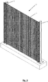
Fig. 3 shows an embodiment of a fence according to the present invention in perspective view; -
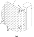
Fig. 4 shows the top right-hand corner of the fence fromFig. 3 in more detail in perspective view; -
Fig. 5 shows the top right-hand corner of the fence fromFig. 3 in more detail in cut-away perspective view. - The fencing mesh (1) illustrated in
Figs 1-5 comprises a first set of wires (2) which are arranged essentially parallel to one another and which, as can be seen inFigs 3-5 , extend essentially horizontally in the fitted position of the fencing mesh (1). In addition to this first set of wires (2), the fencing mesh (1) also comprises a second set of wires (3) which are arranged essentially parallel to one another and extend essentially vertically in the fitted position of the fencing mesh (1). - The wires (2, 3) in each case comprise a round cross section. Alternative cross sections are conceivable, but less preferred. These wires (2, 3) are preferably made of steel.
The wires (2) of the first set have a tensile strength of between 300 MPa and 550 MPa. To this end, they have a diameter of at most 3 mm.
The wires (3) of the second set have a tensile strength of more than 550 MPa. To this end, they have a diameter of at least 3 mm. - In the first embodiment illustrated in
Figs 1-5 , the wires (2) of the first set and the wires (3) of the second set are welded to one another where they intersect. In this way, a fencing mesh (1) having essentially rectangular meshes is obtained.
In the illustrated embodiments, the fencing mesh (1) in each case comprises rectangular meshes. In alternative, but less preferred embodiments, a fencing mesh according to the present invention may also be provided with different kinds of mesh shapes, such as for example diamond-shaped meshes or hexagonal meshes, etc. - The intermediate distance between the wires (2) of the first set is then chosen to be between 15 mm and 35 mm and is preferably essentially 20 mm. The intermediate distance between the wires (3) of the second set is then chosen to be between 30 and 70 mm and is preferably essentially 40 mm. These intermediate distances are preferably measured between the centres of the weld spots of the wires (2, 3). The term "essentially" is used to indicate that these values correspond to the values given within a certain tolerance. For the first set of wires (2), this tolerance is preferably ± 1 mm. For the second set of wires (3), this tolerance is preferably ± 2 mm.
These dimensions and the above-described tensile strengths of the wires (2, 3) are chosen such that the most common rocket-launched grenades can be caught in the meshes, so that this projectile becomes lodged and detonates at the location of this fencing mesh. In this case, the fencing mesh (1) absorbs the kinetic energy of the projectile, due to the flexibility of the wires (2) of the first set. The impact on the fence (5) in this case remains limited to a minimum, partly due to the strength of the wires (3) of the second set. In this way, the fence (5) is as impenetrable as possible, both before and after the impact, partly due to the small intermediate distance between the wires (2) of the first set.
As a result of the strength of the wires (3) of the second set, such a fencing mesh (1) can be made to relatively large sizes and can be placed with a minimum of support. -
Figs 3-5 show how a fencing mesh (1) according to the present invention can be incorporated in a fence (5). This may be effected in a variety of ways by attaching it to posts (4) using all kinds of possible attachment means (6). In the illustrated embodiment, the fencing mesh (1) is attached here to a post (4) by means of attachment means (6) at an intermediate distance. To this end, these attachment means (6) may comprise, for example a bolt (7), nuts (11), washers (8), a clamp (9) and a clamping plate (10), as is illustrated inFig. 5 .
Claims (16)
- Fencing mesh (1) for protecting an interior space from projectiles, comprising a first set of wires (2) which are arranged essentially parallel with respect to each other and a second set of wires (3) which are arranged essentially parallel with respect to each other and intersect the first set of wires (2), wherein the wires (2) of the first set are connected to the wires (3) of the second set at the locations where they intersect and the wires (3) of the second set have a greater tensile strength than the wires (2) of the first set, characterized in that the wires (2, 3) are welded to one another in order to connect them to each other.
- Fencing mesh (1) according to Claim 1, characterized in that the wires (2) of the first set have a tensile strength of less than 550 MPa.
- Fencing mesh (1) according to Claim 2, characterized in that the wires (2) of the first set have a tensile strength of more than 300 MPa.
- Fencing mesh (1) according to any of the preceding claims, characterized in that the wires (2) of the first set have a diameter of at most 3 mm.
- Fencing mesh (1) according to any of the preceding claims, characterized in that the wires (3) of the second set have a tensile strength of more than 550 MPa.
- Fencing mesh (1) according to any of the preceding claims, characterized in that the wires (3) of the second set have a diameter of at least 3 mm.
- Fencing mesh (1) according to any of the preceding claims, characterized in that the intermediate distance between the wires (2) of the first set is smaller than the intermediate distance between the wires (3) of the second set.
- Fencing mesh (1) according to any of the preceding claims, characterized in that the intermediate distance between the wires (2) of the first set is essentially 20 mm.
- Fencing mesh (1) according to any of the preceding claims, characterized in that the intermediate distance between the wires (3) of the second set is essentially 40 mm.
- Fencing mesh (1) according to any of the preceding claims, characterized in that the wires (3) of the second set are made of steel.
- Fencing mesh (1) according to any of the preceding claims, characterized in that the wires (2) of the first set are made of steel.
- Fencing mesh (1) according to any of the preceding claims, characterized in that the wires (2) of the first set intersect the wires (3) of the second set essentially at right angles.
- Fencing mesh (1) according to any of the preceding claims, characterized in that the wires (3) of the second set are designed to extend essentially vertically in the fitted position of the fencing mesh (1).
- Fence (5) for protecting an interior space from projectiles, comprising a post (4) and a fencing mesh (1) which is attached to said post (4), characterized in that the fencing mesh (1) is a fencing mesh (1) according to any of Claims 1 to 13.
- Fence (5) according to Claim 14, characterized in that the wires (2) of the first set are arranged substantially facing the interior space and the wires (3) of the second set are arranged substantially facing away from the interior space.
- Fence (5) according to Claim 14 or 15, characterized in that the fencing mesh (1) is attached to the post (4) at an intermediate distance from said post (4).
Priority Applications (1)
| Application Number | Priority Date | Filing Date | Title |
|---|---|---|---|
| PL15734725T PL3149260T3 (en) | 2014-05-27 | 2015-05-26 | Fencing mesh and fence |
Applications Claiming Priority (2)
| Application Number | Priority Date | Filing Date | Title |
|---|---|---|---|
| BE2014/0404A BE1021258B1 (en) | 2014-05-27 | 2014-05-27 | FENCE Gauze, FENCE AND METHOD FOR MANUFACTURING A FENCE Gauze |
| PCT/IB2015/053922 WO2015181715A1 (en) | 2014-05-27 | 2015-05-26 | Fencing mesh and fence |
Publications (2)
| Publication Number | Publication Date |
|---|---|
| EP3149260A1 EP3149260A1 (en) | 2017-04-05 |
| EP3149260B1 true EP3149260B1 (en) | 2018-03-14 |
Family
ID=51352367
Family Applications (1)
| Application Number | Title | Priority Date | Filing Date |
|---|---|---|---|
| EP15734725.3A Active EP3149260B1 (en) | 2014-05-27 | 2015-05-26 | Fencing mesh and fence |
Country Status (7)
| Country | Link |
|---|---|
| US (1) | US10689879B2 (en) |
| EP (1) | EP3149260B1 (en) |
| BE (1) | BE1021258B1 (en) |
| MA (1) | MA39979A (en) |
| PL (1) | PL3149260T3 (en) |
| SA (1) | SA516380309B1 (en) |
| WO (1) | WO2015181715A1 (en) |
Cited By (2)
| Publication number | Priority date | Publication date | Assignee | Title |
|---|---|---|---|---|
| WO2019197874A1 (en) | 2018-04-10 | 2019-10-17 | Guardiar Europe | Fencing mesh assembly for a fence |
| WO2020245168A1 (en) | 2019-06-04 | 2020-12-10 | Guardiar Europe Bvba | Security fencing |
Families Citing this family (20)
| Publication number | Priority date | Publication date | Assignee | Title |
|---|---|---|---|---|
| US10604962B1 (en) * | 2015-12-01 | 2020-03-31 | Ameristar Perimeter Security Usa Inc. | Barrier infill system |
| US10584513B2 (en) * | 2016-01-08 | 2020-03-10 | Harsco Technologies LLC | Fence structure |
| USD826427S1 (en) * | 2016-04-12 | 2018-08-21 | Cochrane Usa, Inc. | Fence panel |
| US10570640B2 (en) * | 2016-08-31 | 2020-02-25 | Alabama Metal Industries Corporation | Modular perimeter fencing system |
| USD825780S1 (en) * | 2016-12-21 | 2018-08-14 | Cochrane Usa, Inc | Fence panel |
| USD825079S1 (en) * | 2016-12-21 | 2018-08-07 | Cochrane Usa, Inc. | Fence panel |
| CN108716306B (en) * | 2018-04-19 | 2020-08-25 | 厦门川莆太阳能科技有限公司 | Netted guardrail |
| BR112020022783A2 (en) * | 2018-05-10 | 2021-02-02 | Pasquale Impero | road safety barrier |
| US10559232B1 (en) | 2018-07-26 | 2020-02-11 | Utility Compliance Consultants, LLC | Anti-theft sign bracket and sign assembly and method |
| WO2020230173A1 (en) * | 2019-05-14 | 2020-11-19 | Satech Safety Technology S.P.A. | Anchoring assembly and associated fencing |
| GB2591736B (en) * | 2020-01-20 | 2023-02-01 | Praesidiad Holding Bvba | Securing device for fence |
| US12098567B2 (en) | 2020-04-29 | 2024-09-24 | Alabama Metal Industries Corporation | Fencing bracket |
| TWI753635B (en) * | 2020-11-03 | 2022-01-21 | 香港商冠捷投資有限公司 | connection device |
| USD996198S1 (en) | 2020-11-06 | 2023-08-22 | Alabama Metal Industries Corporation | Fencing assembly bracket |
| USD999054S1 (en) | 2020-11-07 | 2023-09-19 | Alabama Metal Industries Corporation | Fencing assembly bracket |
| USD995282S1 (en) | 2020-11-07 | 2023-08-15 | Alabama Metal Industries Corporation | Fencing assembly bracket |
| CN113389429A (en) * | 2021-05-12 | 2021-09-14 | 广船国际有限公司 | Interim protector and interim rail guard, interim flood prevention device |
| USD1075052S1 (en) | 2022-03-14 | 2025-05-13 | Neusch Innovations, Lp | Mesh fence panel |
| CN115962679B (en) * | 2022-12-28 | 2025-05-13 | 海底鹰深海科技股份有限公司 | Floating device and method for assembling floating device and defending net |
| USD1080916S1 (en) * | 2024-09-30 | 2025-06-24 | Guangzhou Mibo Zhilian Technology Co. Ltd | Fence |
Family Cites Families (27)
| Publication number | Priority date | Publication date | Assignee | Title |
|---|---|---|---|---|
| CA1056178A (en) * | 1976-01-19 | 1979-06-12 | Morris Schupack | Reinforced panel structures and methods for producing them |
| DE2650578A1 (en) * | 1976-11-04 | 1978-05-11 | Arbed | KNOTS |
| US4209153A (en) * | 1977-06-14 | 1980-06-24 | N. V. Bekaert S.A. | Functional mesh or netting |
| AT390578B (en) * | 1988-03-31 | 1990-05-25 | Evg Entwicklung Verwert Ges | MULTIPLE POINT WELDING MACHINE |
| GB9014205D0 (en) * | 1990-06-26 | 1990-10-17 | Passive Barriers Ltd | Yielding barriers |
| BE1007664A3 (en) * | 1993-10-21 | 1995-09-05 | Bekaert Sa Nv | Closure with bars panels. |
| US6010116A (en) * | 1997-11-14 | 2000-01-04 | Knott, Sr.; James M. | High security fence assembly |
| CH692921A5 (en) * | 1998-02-25 | 2002-12-13 | Fatzer Ag | Wire mesh preferably as rockfall protection or for securing a Erdoberflächenschicht. |
| GB0212687D0 (en) | 2002-05-31 | 2002-07-10 | Composhield As | Reinforced composite panel |
| AT6497U1 (en) * | 2002-11-19 | 2003-11-25 | H & S Zauntechnik Ges M B H | DEVICE FOR FASTENING FENCE MATS ON FENCING PILLARS |
| CH697096A5 (en) | 2004-06-08 | 2008-04-30 | Fatzer Ag | Safety net, especially for rockfall protection or for verge securing. |
| FR2871829B1 (en) * | 2004-06-17 | 2006-08-11 | Clotex Soc Par Actions Simplif | FIXING DEVICE FOR A CLOSING GRID ON A POST AND CLOSING USING SAID ORGANS |
| US20060038165A1 (en) * | 2004-08-18 | 2006-02-23 | Charles Larsen | Fence apparatus and related methods |
| US7866635B2 (en) * | 2005-01-07 | 2011-01-11 | Payne Fence Products, Llc | Fence system |
| EP1712710A1 (en) | 2005-04-14 | 2006-10-18 | Betafence Holding NV | Post with fixing bracket |
| US20080308780A1 (en) * | 2007-04-09 | 2008-12-18 | Sloan Security Fencing, Inc. | Security fence system |
| US8056855B2 (en) * | 2008-06-05 | 2011-11-15 | Konstantinovskiy Alexandr | Missile interceptor with net body |
| GB0810657D0 (en) * | 2008-06-11 | 2008-07-16 | Mccalister Andrew | Blast absorption device |
| US20090321701A1 (en) * | 2008-06-30 | 2009-12-31 | Payne Fence Products, Llc | Fence System |
| US20110062404A1 (en) * | 2009-09-14 | 2011-03-17 | C.E. Shepherd Company, L.P. | Wire-Mesh Security Fence and Fence Panel |
| US9695613B2 (en) * | 2009-09-14 | 2017-07-04 | C. E. Shepherd Company, L.P. | Wire-mesh security fences, methods and systems and fence panels |
| US20140353564A1 (en) * | 2009-09-14 | 2014-12-04 | C.E. Shepherd Company, L.P. | Wire-Mesh Security Fence and Fence Panel |
| US20130069027A1 (en) * | 2010-03-26 | 2013-03-21 | Ingo Zimmermann | Safety Barrier |
| US8840089B2 (en) * | 2010-09-02 | 2014-09-23 | Electra-Lock Fence Systems, Inc. | Electric web fence |
| AU2011100489B4 (en) * | 2010-12-15 | 2011-08-11 | Pro3 Safety Pty Ltd | System and components for safely enclosing handrails, stairways, walkways and platforms |
| AU2013225238B2 (en) * | 2012-02-28 | 2016-10-20 | Minova International Limited | Knotted mesh as supporting material in mines |
| BE1021457B1 (en) * | 2012-11-29 | 2015-11-26 | Betafence Holding Nv | SAFETY FENCE PANEL AND SAFETY FENCE |
-
2014
- 2014-05-27 BE BE2014/0404A patent/BE1021258B1/en not_active IP Right Cessation
-
2015
- 2015-05-26 EP EP15734725.3A patent/EP3149260B1/en active Active
- 2015-05-26 WO PCT/IB2015/053922 patent/WO2015181715A1/en not_active Ceased
- 2015-05-26 PL PL15734725T patent/PL3149260T3/en unknown
- 2015-05-26 MA MA039979A patent/MA39979A/en unknown
- 2015-05-26 US US15/314,328 patent/US10689879B2/en not_active Expired - Fee Related
-
2016
- 2016-11-15 SA SA516380309A patent/SA516380309B1/en unknown
Cited By (2)
| Publication number | Priority date | Publication date | Assignee | Title |
|---|---|---|---|---|
| WO2019197874A1 (en) | 2018-04-10 | 2019-10-17 | Guardiar Europe | Fencing mesh assembly for a fence |
| WO2020245168A1 (en) | 2019-06-04 | 2020-12-10 | Guardiar Europe Bvba | Security fencing |
Also Published As
| Publication number | Publication date |
|---|---|
| PL3149260T3 (en) | 2018-11-30 |
| US20170096835A1 (en) | 2017-04-06 |
| SA516380309B1 (en) | 2019-03-25 |
| US10689879B2 (en) | 2020-06-23 |
| BE1021258B1 (en) | 2015-10-07 |
| WO2015181715A1 (en) | 2015-12-03 |
| EP3149260A1 (en) | 2017-04-05 |
| MA39979A (en) | 2017-04-05 |
Similar Documents
| Publication | Publication Date | Title |
|---|---|---|
| US10689879B2 (en) | Fencing mesh and fence | |
| US8132495B2 (en) | Multilayer armor system for defending against missile-borne and stationary shaped charges | |
| US8453552B2 (en) | Method of designing an RPG shield | |
| CA2692757A1 (en) | Flexible web to confront rocket propelled grenades | |
| CA2855486C (en) | Vehicle and structure shield with improved hard points | |
| WO2012134597A1 (en) | Low breaking strength vehicle and structure shield net/frame arrangement | |
| US8677882B2 (en) | Vehicle and structure shield with flexible frame | |
| US20140373707A1 (en) | Arrangement for the protection of an object, especially of a motor vehicle, against approaching projectiles | |
| US20170063054A1 (en) | Protective barriers and related methods | |
| EP2167903B1 (en) | Flexible web to confront rocket propelled grenades | |
| WO2018194766A1 (en) | Improved hard point net | |
| KR20200093915A (en) | Proximity explosion protection system to reduce bursting pressure | |
| JP2016079766A (en) | Tornado protection net | |
| EP3128282A2 (en) | Security fence assembly method for ballistic purposes | |
| WO2015157179A1 (en) | Infrastructure armor system | |
| GB2534197A (en) | Protective wall | |
| RU2846946C1 (en) | Flexible vehicle protection system | |
| Szudrowicz | Analysis of bar and net screens structure protecting vehicles against anti-tank grenades fired from RPG-7 | |
| WO2011123086A1 (en) | Multilayer armor system for defending against missile-borne and stationary shaped charges | |
| EP3757505B1 (en) | A balistic protective net module | |
| KR20110116410A (en) | Explosive Gloves for Combat Vehicles | |
| US20160236264A1 (en) | Protecting Net | |
| WO2018065791A1 (en) | Improved vehicle armour | |
| RU2488765C1 (en) | Anti-ricochet and anti-fragmentation protection of living or cargo compartment | |
| WO2014065924A1 (en) | Vehicle and structure shield with flexible frame |
Legal Events
| Date | Code | Title | Description |
|---|---|---|---|
| PUAI | Public reference made under article 153(3) epc to a published international application that has entered the european phase |
Free format text: ORIGINAL CODE: 0009012 |
|
| 17P | Request for examination filed |
Effective date: 20161213 |
|
| AK | Designated contracting states |
Kind code of ref document: A1 Designated state(s): AL AT BE BG CH CY CZ DE DK EE ES FI FR GB GR HR HU IE IS IT LI LT LU LV MC MK MT NL NO PL PT RO RS SE SI SK SM TR |
|
| AX | Request for extension of the european patent |
Extension state: BA ME |
|
| DAX | Request for extension of the european patent (deleted) | ||
| GRAP | Despatch of communication of intention to grant a patent |
Free format text: ORIGINAL CODE: EPIDOSNIGR1 |
|
| RIC1 | Information provided on ipc code assigned before grant |
Ipc: E04H 17/20 20060101ALI20171031BHEP Ipc: F41H 5/013 20060101ALI20171031BHEP Ipc: E04H 17/16 20060101AFI20171031BHEP Ipc: F41H 5/02 20060101ALI20171031BHEP |
|
| INTG | Intention to grant announced |
Effective date: 20171201 |
|
| GRAS | Grant fee paid |
Free format text: ORIGINAL CODE: EPIDOSNIGR3 |
|
| GRAA | (expected) grant |
Free format text: ORIGINAL CODE: 0009210 |
|
| RAP1 | Party data changed (applicant data changed or rights of an application transferred) |
Owner name: BETAFENCE HOLDING NV |
|
| AK | Designated contracting states |
Kind code of ref document: B1 Designated state(s): AL AT BE BG CH CY CZ DE DK EE ES FI FR GB GR HR HU IE IS IT LI LT LU LV MC MK MT NL NO PL PT RO RS SE SI SK SM TR |
|
| REG | Reference to a national code |
Ref country code: GB Ref legal event code: FG4D |
|
| REG | Reference to a national code |
Ref country code: AT Ref legal event code: REF Ref document number: 979042 Country of ref document: AT Kind code of ref document: T Effective date: 20180315 Ref country code: CH Ref legal event code: EP |
|
| REG | Reference to a national code |
Ref country code: IE Ref legal event code: FG4D |
|
| REG | Reference to a national code |
Ref country code: DE Ref legal event code: R096 Ref document number: 602015008896 Country of ref document: DE |
|
| REG | Reference to a national code |
Ref country code: NL Ref legal event code: MP Effective date: 20180314 |
|
| REG | Reference to a national code |
Ref country code: LT Ref legal event code: MG4D |
|
| PG25 | Lapsed in a contracting state [announced via postgrant information from national office to epo] |
Ref country code: LT Free format text: LAPSE BECAUSE OF FAILURE TO SUBMIT A TRANSLATION OF THE DESCRIPTION OR TO PAY THE FEE WITHIN THE PRESCRIBED TIME-LIMIT Effective date: 20180314 Ref country code: NO Free format text: LAPSE BECAUSE OF FAILURE TO SUBMIT A TRANSLATION OF THE DESCRIPTION OR TO PAY THE FEE WITHIN THE PRESCRIBED TIME-LIMIT Effective date: 20180614 Ref country code: FI Free format text: LAPSE BECAUSE OF FAILURE TO SUBMIT A TRANSLATION OF THE DESCRIPTION OR TO PAY THE FEE WITHIN THE PRESCRIBED TIME-LIMIT Effective date: 20180314 Ref country code: CY Free format text: LAPSE BECAUSE OF FAILURE TO SUBMIT A TRANSLATION OF THE DESCRIPTION OR TO PAY THE FEE WITHIN THE PRESCRIBED TIME-LIMIT Effective date: 20180314 Ref country code: HR Free format text: LAPSE BECAUSE OF FAILURE TO SUBMIT A TRANSLATION OF THE DESCRIPTION OR TO PAY THE FEE WITHIN THE PRESCRIBED TIME-LIMIT Effective date: 20180314 |
|
| REG | Reference to a national code |
Ref country code: MA Ref legal event code: VAGR Ref document number: 39979 Country of ref document: MA Kind code of ref document: B1 |
|
| REG | Reference to a national code |
Ref country code: AT Ref legal event code: MK05 Ref document number: 979042 Country of ref document: AT Kind code of ref document: T Effective date: 20180314 |
|
| PG25 | Lapsed in a contracting state [announced via postgrant information from national office to epo] |
Ref country code: GR Free format text: LAPSE BECAUSE OF FAILURE TO SUBMIT A TRANSLATION OF THE DESCRIPTION OR TO PAY THE FEE WITHIN THE PRESCRIBED TIME-LIMIT Effective date: 20180615 Ref country code: BG Free format text: LAPSE BECAUSE OF FAILURE TO SUBMIT A TRANSLATION OF THE DESCRIPTION OR TO PAY THE FEE WITHIN THE PRESCRIBED TIME-LIMIT Effective date: 20180614 Ref country code: RS Free format text: LAPSE BECAUSE OF FAILURE TO SUBMIT A TRANSLATION OF THE DESCRIPTION OR TO PAY THE FEE WITHIN THE PRESCRIBED TIME-LIMIT Effective date: 20180314 Ref country code: LV Free format text: LAPSE BECAUSE OF FAILURE TO SUBMIT A TRANSLATION OF THE DESCRIPTION OR TO PAY THE FEE WITHIN THE PRESCRIBED TIME-LIMIT Effective date: 20180314 Ref country code: SE Free format text: LAPSE BECAUSE OF FAILURE TO SUBMIT A TRANSLATION OF THE DESCRIPTION OR TO PAY THE FEE WITHIN THE PRESCRIBED TIME-LIMIT Effective date: 20180314 |
|
| PG25 | Lapsed in a contracting state [announced via postgrant information from national office to epo] |
Ref country code: AL Free format text: LAPSE BECAUSE OF FAILURE TO SUBMIT A TRANSLATION OF THE DESCRIPTION OR TO PAY THE FEE WITHIN THE PRESCRIBED TIME-LIMIT Effective date: 20180314 Ref country code: NL Free format text: LAPSE BECAUSE OF FAILURE TO SUBMIT A TRANSLATION OF THE DESCRIPTION OR TO PAY THE FEE WITHIN THE PRESCRIBED TIME-LIMIT Effective date: 20180314 Ref country code: EE Free format text: LAPSE BECAUSE OF FAILURE TO SUBMIT A TRANSLATION OF THE DESCRIPTION OR TO PAY THE FEE WITHIN THE PRESCRIBED TIME-LIMIT Effective date: 20180314 Ref country code: RO Free format text: LAPSE BECAUSE OF FAILURE TO SUBMIT A TRANSLATION OF THE DESCRIPTION OR TO PAY THE FEE WITHIN THE PRESCRIBED TIME-LIMIT Effective date: 20180314 Ref country code: ES Free format text: LAPSE BECAUSE OF FAILURE TO SUBMIT A TRANSLATION OF THE DESCRIPTION OR TO PAY THE FEE WITHIN THE PRESCRIBED TIME-LIMIT Effective date: 20180314 |
|
| PG25 | Lapsed in a contracting state [announced via postgrant information from national office to epo] |
Ref country code: CZ Free format text: LAPSE BECAUSE OF FAILURE TO SUBMIT A TRANSLATION OF THE DESCRIPTION OR TO PAY THE FEE WITHIN THE PRESCRIBED TIME-LIMIT Effective date: 20180314 Ref country code: AT Free format text: LAPSE BECAUSE OF FAILURE TO SUBMIT A TRANSLATION OF THE DESCRIPTION OR TO PAY THE FEE WITHIN THE PRESCRIBED TIME-LIMIT Effective date: 20180314 Ref country code: SK Free format text: LAPSE BECAUSE OF FAILURE TO SUBMIT A TRANSLATION OF THE DESCRIPTION OR TO PAY THE FEE WITHIN THE PRESCRIBED TIME-LIMIT Effective date: 20180314 Ref country code: SM Free format text: LAPSE BECAUSE OF FAILURE TO SUBMIT A TRANSLATION OF THE DESCRIPTION OR TO PAY THE FEE WITHIN THE PRESCRIBED TIME-LIMIT Effective date: 20180314 |
|
| REG | Reference to a national code |
Ref country code: CH Ref legal event code: PL |
|
| REG | Reference to a national code |
Ref country code: DE Ref legal event code: R097 Ref document number: 602015008896 Country of ref document: DE |
|
| PG25 | Lapsed in a contracting state [announced via postgrant information from national office to epo] |
Ref country code: PT Free format text: LAPSE BECAUSE OF FAILURE TO SUBMIT A TRANSLATION OF THE DESCRIPTION OR TO PAY THE FEE WITHIN THE PRESCRIBED TIME-LIMIT Effective date: 20180716 |
|
| PLBE | No opposition filed within time limit |
Free format text: ORIGINAL CODE: 0009261 |
|
| STAA | Information on the status of an ep patent application or granted ep patent |
Free format text: STATUS: NO OPPOSITION FILED WITHIN TIME LIMIT |
|
| PG25 | Lapsed in a contracting state [announced via postgrant information from national office to epo] |
Ref country code: DK Free format text: LAPSE BECAUSE OF FAILURE TO SUBMIT A TRANSLATION OF THE DESCRIPTION OR TO PAY THE FEE WITHIN THE PRESCRIBED TIME-LIMIT Effective date: 20180314 Ref country code: MC Free format text: LAPSE BECAUSE OF FAILURE TO SUBMIT A TRANSLATION OF THE DESCRIPTION OR TO PAY THE FEE WITHIN THE PRESCRIBED TIME-LIMIT Effective date: 20180314 |
|
| 26N | No opposition filed |
Effective date: 20181217 |
|
| REG | Reference to a national code |
Ref country code: IE Ref legal event code: MM4A |
|
| PG25 | Lapsed in a contracting state [announced via postgrant information from national office to epo] |
Ref country code: CH Free format text: LAPSE BECAUSE OF NON-PAYMENT OF DUE FEES Effective date: 20180531 Ref country code: LI Free format text: LAPSE BECAUSE OF NON-PAYMENT OF DUE FEES Effective date: 20180531 |
|
| REG | Reference to a national code |
Ref country code: BE Ref legal event code: PD Owner name: GUARDIAR EUROPE; BE Free format text: DETAILS ASSIGNMENT: CHANGE OF OWNER(S), CESSION; FORMER OWNER NAME: BETAFENCE HOLDING NV Effective date: 20190131 |
|
| PG25 | Lapsed in a contracting state [announced via postgrant information from national office to epo] |
Ref country code: LU Free format text: LAPSE BECAUSE OF NON-PAYMENT OF DUE FEES Effective date: 20180526 |
|
| PG25 | Lapsed in a contracting state [announced via postgrant information from national office to epo] |
Ref country code: FR Free format text: LAPSE BECAUSE OF NON-PAYMENT OF DUE FEES Effective date: 20180531 Ref country code: IE Free format text: LAPSE BECAUSE OF NON-PAYMENT OF DUE FEES Effective date: 20180526 |
|
| VSFP | Annual fee paid to validation state [announced via postgrant information from national office to epo] |
Ref country code: MA Payment date: 20180525 Year of fee payment: 4 |
|
| PGFP | Annual fee paid to national office [announced via postgrant information from national office to epo] |
Ref country code: IT Payment date: 20190527 Year of fee payment: 5 Ref country code: PL Payment date: 20190514 Year of fee payment: 5 |
|
| PG25 | Lapsed in a contracting state [announced via postgrant information from national office to epo] |
Ref country code: MT Free format text: LAPSE BECAUSE OF NON-PAYMENT OF DUE FEES Effective date: 20180526 |
|
| PG25 | Lapsed in a contracting state [announced via postgrant information from national office to epo] |
Ref country code: TR Free format text: LAPSE BECAUSE OF FAILURE TO SUBMIT A TRANSLATION OF THE DESCRIPTION OR TO PAY THE FEE WITHIN THE PRESCRIBED TIME-LIMIT Effective date: 20180314 |
|
| VSFP | Annual fee paid to validation state [announced via postgrant information from national office to epo] |
Ref country code: MA Payment date: 20190522 Year of fee payment: 5 |
|
| PG25 | Lapsed in a contracting state [announced via postgrant information from national office to epo] |
Ref country code: HU Free format text: LAPSE BECAUSE OF FAILURE TO SUBMIT A TRANSLATION OF THE DESCRIPTION OR TO PAY THE FEE WITHIN THE PRESCRIBED TIME-LIMIT; INVALID AB INITIO Effective date: 20150526 Ref country code: MK Free format text: LAPSE BECAUSE OF NON-PAYMENT OF DUE FEES Effective date: 20180314 |
|
| PG25 | Lapsed in a contracting state [announced via postgrant information from national office to epo] |
Ref country code: IS Free format text: LAPSE BECAUSE OF FAILURE TO SUBMIT A TRANSLATION OF THE DESCRIPTION OR TO PAY THE FEE WITHIN THE PRESCRIBED TIME-LIMIT Effective date: 20180714 |
|
| PG25 | Lapsed in a contracting state [announced via postgrant information from national office to epo] |
Ref country code: SI Free format text: LAPSE BECAUSE OF NON-PAYMENT OF DUE FEES Effective date: 20180526 |
|
| PG25 | Lapsed in a contracting state [announced via postgrant information from national office to epo] |
Ref country code: IT Free format text: LAPSE BECAUSE OF NON-PAYMENT OF DUE FEES Effective date: 20200526 |
|
| PG25 | Lapsed in a contracting state [announced via postgrant information from national office to epo] |
Ref country code: PL Free format text: LAPSE BECAUSE OF NON-PAYMENT OF DUE FEES Effective date: 20200526 |
|
| P01 | Opt-out of the competence of the unified patent court (upc) registered |
Effective date: 20230526 |
|
| VS25 | Lapsed in a validation state [announced via postgrant information from nat. office to epo] |
Ref country code: MA Free format text: LAPSE BECAUSE OF NON-PAYMENT OF DUE FEES Effective date: 20200527 |
|
| PGFP | Annual fee paid to national office [announced via postgrant information from national office to epo] |
Ref country code: DE Payment date: 20250520 Year of fee payment: 11 |
|
| PGFP | Annual fee paid to national office [announced via postgrant information from national office to epo] |
Ref country code: GB Payment date: 20250519 Year of fee payment: 11 |
|
| PGFP | Annual fee paid to national office [announced via postgrant information from national office to epo] |
Ref country code: BE Payment date: 20250522 Year of fee payment: 11 |
|
| VSFP | Annual fee paid to validation state [announced via postgrant information from national office to epo] |
Ref country code: MA Payment date: 20190522 Year of fee payment: 5 |