EP3148611B1 - Infusion system and pump with configurable closed loop delivery rate catch-up - Google Patents
Infusion system and pump with configurable closed loop delivery rate catch-up Download PDFInfo
- Publication number
- EP3148611B1 EP3148611B1 EP15799090.4A EP15799090A EP3148611B1 EP 3148611 B1 EP3148611 B1 EP 3148611B1 EP 15799090 A EP15799090 A EP 15799090A EP 3148611 B1 EP3148611 B1 EP 3148611B1
- Authority
- EP
- European Patent Office
- Prior art keywords
- infusion
- rate
- catch
- pump
- drug
- Prior art date
- Legal status (The legal status is an assumption and is not a legal conclusion. Google has not performed a legal analysis and makes no representation as to the accuracy of the status listed.)
- Active
Links
Images


Classifications
-
- A—HUMAN NECESSITIES
- A61—MEDICAL OR VETERINARY SCIENCE; HYGIENE
- A61M—DEVICES FOR INTRODUCING MEDIA INTO, OR ONTO, THE BODY; DEVICES FOR TRANSDUCING BODY MEDIA OR FOR TAKING MEDIA FROM THE BODY; DEVICES FOR PRODUCING OR ENDING SLEEP OR STUPOR
- A61M5/00—Devices for bringing media into the body in a subcutaneous, intra-vascular or intramuscular way; Accessories therefor, e.g. filling or cleaning devices, arm-rests
- A61M5/14—Infusion devices, e.g. infusing by gravity; Blood infusion; Accessories therefor
- A61M5/168—Means for controlling media flow to the body or for metering media to the body, e.g. drip meters, counters ; Monitoring media flow to the body
- A61M5/16804—Flow controllers
- A61M5/16827—Flow controllers controlling delivery of multiple fluids, e.g. sequencing, mixing or via separate flow-paths
-
- G—PHYSICS
- G16—INFORMATION AND COMMUNICATION TECHNOLOGY [ICT] SPECIALLY ADAPTED FOR SPECIFIC APPLICATION FIELDS
- G16H—HEALTHCARE INFORMATICS, i.e. INFORMATION AND COMMUNICATION TECHNOLOGY [ICT] SPECIALLY ADAPTED FOR THE HANDLING OR PROCESSING OF MEDICAL OR HEALTHCARE DATA
- G16H20/00—ICT specially adapted for therapies or health-improving plans, e.g. for handling prescriptions, for steering therapy or for monitoring patient compliance
- G16H20/10—ICT specially adapted for therapies or health-improving plans, e.g. for handling prescriptions, for steering therapy or for monitoring patient compliance relating to drugs or medications, e.g. for ensuring correct administration to patients
- G16H20/17—ICT specially adapted for therapies or health-improving plans, e.g. for handling prescriptions, for steering therapy or for monitoring patient compliance relating to drugs or medications, e.g. for ensuring correct administration to patients delivered via infusion or injection
-
- G—PHYSICS
- G16—INFORMATION AND COMMUNICATION TECHNOLOGY [ICT] SPECIALLY ADAPTED FOR SPECIFIC APPLICATION FIELDS
- G16H—HEALTHCARE INFORMATICS, i.e. INFORMATION AND COMMUNICATION TECHNOLOGY [ICT] SPECIALLY ADAPTED FOR THE HANDLING OR PROCESSING OF MEDICAL OR HEALTHCARE DATA
- G16H40/00—ICT specially adapted for the management or administration of healthcare resources or facilities; ICT specially adapted for the management or operation of medical equipment or devices
- G16H40/60—ICT specially adapted for the management or administration of healthcare resources or facilities; ICT specially adapted for the management or operation of medical equipment or devices for the operation of medical equipment or devices
- G16H40/63—ICT specially adapted for the management or administration of healthcare resources or facilities; ICT specially adapted for the management or operation of medical equipment or devices for the operation of medical equipment or devices for local operation
-
- A—HUMAN NECESSITIES
- A61—MEDICAL OR VETERINARY SCIENCE; HYGIENE
- A61M—DEVICES FOR INTRODUCING MEDIA INTO, OR ONTO, THE BODY; DEVICES FOR TRANSDUCING BODY MEDIA OR FOR TAKING MEDIA FROM THE BODY; DEVICES FOR PRODUCING OR ENDING SLEEP OR STUPOR
- A61M5/00—Devices for bringing media into the body in a subcutaneous, intra-vascular or intramuscular way; Accessories therefor, e.g. filling or cleaning devices, arm-rests
- A61M5/14—Infusion devices, e.g. infusing by gravity; Blood infusion; Accessories therefor
- A61M5/168—Means for controlling media flow to the body or for metering media to the body, e.g. drip meters, counters ; Monitoring media flow to the body
- A61M5/172—Means for controlling media flow to the body or for metering media to the body, e.g. drip meters, counters ; Monitoring media flow to the body electrical or electronic
- A61M5/1723—Means for controlling media flow to the body or for metering media to the body, e.g. drip meters, counters ; Monitoring media flow to the body electrical or electronic using feedback of body parameters, e.g. blood-sugar, pressure
Definitions
- the present invention relates to medical devices. More specifically, the invention relates to infusion systems and pumps with configurable closed loop delivery rate catch-up.
- Infusion pumps are medical devices that deliver fluids, including nutrients and medications such as antibiotics, chemotherapy drugs, and pain relievers, into a patient's body in controlled amounts.
- Many types of pumps including large volume, patient-controlled analgesia (PCA), elastomeric, syringe, enteral, and insulin pumps, are used worldwide in healthcare facilities such as hospitals, and in the home. Clinicians and patients rely on pumps for safe and accurate administration of fluids and medications.
- PCA patient-controlled analgesia
- elastomeric, syringe, enteral, and insulin pumps are used worldwide in healthcare facilities such as hospitals, and in the home. Clinicians and patients rely on pumps for safe and accurate administration of fluids and medications.
- the desired pumping or volumetric flow rate is input directly, or calculated from an input volume to be infused and delivery period or duration, and the infusion pump operates at a single target motor speed or stroke frequency to deliver the desired pumping or flow rate regardless of external conditions.
- flow delivery can be interrupted by a variety of conditions, such as a stoppage or pause based upon a full or partial occlusion, a kinked tube, an air-in-line alarm, hanging a new IV bag, vein clot, or the like. Once the flow delivery is interrupted, the time in which there is no medication delivery is lost, resulting in a delay in desired infusion completion.
- Nurses typically work in shifts and expect certain medications to be started and/or finished within their shift and plan accordingly. When occlusions, pauses, or other disturbances interrupt or delay medication delivery, this disrupts the nurses' planning for patient care within their respective shifts. In addition, the patients in these scenarios would not receive the medicine required within the allotted time.
- US 5,522,798 discloses a host controller to controls drug concentrations for each of a plurality of channels delivered through multiple drug channels of a multi-channel drug delivery system.
- the host controller includes a controller that is coupled to each drug channel of the multichannel drug delivery system to receive actual drug delivery rate information.
- US 4,525,163 discloses a controller for an intravenous set which operates both to maintain the instantaneous drip rate through a drip chamber included in the IV set at a desired value, and to modify this value repeatedly during the course of an infusion.
- the desired drip value is modified in accordance with the measured volumetric flow rate through the intravenous set such that if a particular infusion fluid produces abnormally small volume drops in the drip chamber, then the controller automatically increases the drip rate to compensate.
- US 2006/0270971 discloses a patient hydration system including an infusion device for administering hydration fluid to a patient and a patient urine output measurement device. If a disruption is detected, a controller software calculates an amount of urine made by a patient during the disruption using weight measurements, and the system increases the infusion rate.
- US 2002/0077852 discloses a system for creating a customized drug library for an electronically loadable drug infusion pump, the system including a drug library containing a plurality of drug entries, there being associated with each drug entry a set of associated drug delivery parameters and/or drug delivery protocols for configuring the drug infusion pump.
- US 2006/0064053 discloses an infusion system comprising a first pump device that delivers a first infusate to an IV infusion line and a second pump device that delivers a second infusate to the IV line.
- a measurement device determines an amount of undelivered first infusate remaining in a receptacle.
- a control system communicates with the first and second delivery devices and the measurement device to determine an optimum first infusate infusion flow rate based on the determined amount of undelivered first infusate remaining in the system, a predetermined volume of fluid to be infused, and a predetermined infusion time period.
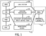
- FIG. 1 is a schematic diagram of the medication management system including a medication management unit and a medical device integrated with an information system, in accordance with the present invention.
- the medication management system (MMS) 10 includes a medication management unit (MMU) 12 and a medical device 14, typically operating in a hospital environment 16.
- MMU medication management unit
- the term hospital environment as defined herein is used broadly to mean any medical care facility, including but not limited to a hospital, treatment center, clinic, doctor's office, day surgery center, hospice, nursing home, and any of the above associated with a home care environment.
- the MMU 12 communicates to a hospital information system (HIS) 18 via a caching mechanism 20 that is part of the hospital environment 16.
- HIS hospital information system
- the caching mechanism 20 is primarily a pass through device for facilitating communication with the HIS 18 and its functions can be eliminated or incorporated into the MMU 12 ( FIG. 1 ) and/or the medical device 14 and/or the HIS 18 and/or other information systems or components within the hospital environment 16.
- the caching mechanism 20 provides temporary storage of hospital information data separate from the HIS 18, the medication administration record system (MAR) 22, pharmacy information system (PhIS) 24, physician order entry (POE) 26, and/or Lab System 28.
- the caching mechanism 20 provides information storage accessible to the medication management system 10 to support scenarios where direct access to data within the hospital environment 16 is not available or not desired.
- the caching mechanism 20 provides continued flow of information in and out of the MMU 12 in instances where the HIS 18 is down or the connectivity between the MMU 12 and the electronic network (not shown) is down.
- the HIS 18 communicates with a medication administration record system (MAR) 22 for maintaining medication records and a pharmacy information system (PhIS) 24 for delivering drug orders to the HIS.
- MAR medication administration record system
- PrIS pharmacy information system
- a physician/provider order entry (POE) device 26 permits a healthcare provider to deliver a medication order prescribed for a patient to the hospital information system directly or indirectly via the PhIS 24.
- a medication order can be sent to the MMU 12 directly from the PhIS 24 or POE device 26.
- the term medication order is defined as an order to administer something that has a physiological impact on a person or animal, including but not limited to liquid or gaseous fluids, drugs or medicines, liquid nutritional products and combinations thereof.
- Lab system 28 and monitoring device 30 also communicate with the MMU 12 to deliver updated patient-specific information to the MMU 12.
- the MMU 12 communicates directly to the lab system 28 and monitoring device 30.
- the MMU 12 can communicate with the lab system 28 and monitoring device 30 indirectly via the HIS 18, the caching mechanism 20, the medical device 14 or some other intermediary device or system.
- Delivery information input device 32 also communicates with the MMU 12 to assist in processing drug orders for delivery through the MMU 12.
- the delivery information input device 32 can be any sort of data input means, including those adapted to read machine readable indicia such as barcode labels; for example a personal digital assistant (PDA) with a barcode scanner.
- PDA personal digital assistant
- the delivery information input device 32 is referred to as input device 32.
- the machine readable indicia can be in other known forms, such as radio frequency identification (RFID) tag, two-dimensional bar code, ID matrix, transmitted radio ID code, human biometric data such as fingerprints, etc. and the input device 32 adapted to "read” or recognize such indicia.
- RFID radio frequency identification
- the input device 32 is shown as a separate device from the medical device 14; alternatively, the input device 32 communicates directly with the medical device 14 or can be integrated wholly or in part with the medical device.
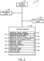
- FIG. 2 is a schematic diagram of the medication management unit, in accordance with the present invention.
- the medication management unit 12 includes a network interface 34 for connecting the MMU 12 to multiple components of a hospital environment 16, one or more medical devices 14, and any other desired device or network.
- a processing unit 36 is included in MMU 12 and performs various operations described in greater detail below.
- a display/input or user interface device 38 communicates with the processing unit 36 and allows the user to receive output from processing unit 36 and/or input information into the processing unit 36.
- the display/input device 38 can be provided as a separate display device and a separate input device.
- An electronic storage medium 40 communicates with the processing unit 36 and stores programming code and data necessary for the processing unit 36 to perform the functions of the MMU 12. More specifically, the storage medium 40 stores multiple programs formed in accordance with the present invention for various functions of the MMU 12 including but not limited to the following programs: Maintain Drug Library 42; Download Drug Library 44; Process Drug Order 46; Maintain Expert Clinical Rules 48; Apply Expert Clinical Rules 50; Monitor Pumps 52; Monitor Lines 54; Generate Reports 56; View Data 58; Configure the MMS 60; and Monitor the MMS 62.
- the Maintain Drug Library 42 program creates, updates, and deletes drug entries and establishes a current active drug library.
- the Download Drug Library 44 program updates medical devices 14 with the current drug library.
- the Process Drug Order 46 program processes the medication order for a patient, verifying that the point of care (POC) medication and delivery parameters match those ordered.
- the Maintain Expert Clinical Rules 48 program creates, updates, and deletes the rules that describe the hospital's therapy and protocol regimens.
- the Apply Expert Clinical Rules 50 program performs logic processing to ensure safety and considers other infusions or medication orders, patient demographics, and current patient conditions.
- the Monitor Pumps 52 program acquires ongoing updates of status events, and alarms transmitted both near real-time and in batch mode, as well as tracking the location, current assignment, and software versions such as the drug library version residing on medical device 14.
- the Monitor Lines 54 program acquires ongoing updates of status, events and alarms for each channel or line for a medical device 14 that supports multiple drug delivery channels or lines.
- the Generate Reports 56 program provides a mechanism that allows the user to generate various reports of the data held in the MMU storage medium 40.
- the View Data 58 program provides a mechanism that supports various display or view capabilities for users of the MMU 12.
- the Notifications 59 program provides a mechanism for scheduling and delivery of events to external systems and users.
- the Configure the MMS 60 program provides a mechanism for system administrators to install and configure the MMS 10.
- the Monitor the MMS 62 program enables information technology operations staff capabilities to see the current status of MMS 10 components and processing, and other aspects of day-to-day operations such as system start up, shut down, backup and restore.
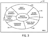
- FIG. 3 is a schematic diagram of some of the major functions performed by the medication management unit, in accordance with the present invention.
- the various functional programs 42-62 of the MMU 12, each including separate features and rules, are partitioned (at a higher level than shown in FIG. 2 ) and logically organized into interrelated managing units of the MMU 12.
- the MMU 12 includes an asset manager 64, an alarm manager 66, a drug library manager (such as, for example, is included in HOSPIRA MEDNETTM software) 68, a caregiver manager 70, a therapy manager 72, and/or a clinical data manager 73.
- the MMU 12 includes a master adjudicator 74 between the separate interrelated managing units 64-73 of the MMU 12, to regulate the interaction between the separate management units.
- the MMU 12 as described herein appears as a single device, there can be more than one MMU 12 operating harmoniously and sharing the same database.
- the MMU 12 can consist of a collection of MMU specific applications running on distinct servers in order to avoid a single point of failure, address availability requirements, and handle a high volume of requests.
- each individual server portion of the MMU 12 operates in conjunction with other server portions of the MMU 12 to redirect service requests to another server portion of the MMU 12.
- the master adjudicator 74 assigns redirected service requests to another server portion of the MMU 12, prioritizing each request and also ensuring that each request is processed.
- the managing units 64-72 each include separate features and rules to govern their operation.
- the asset manager 64 governs the execution of the Monitor Pumps 52 and Monitor Lines 54 programs
- the drug library manager 68 governs the execution of the Drug Library 42 and Download Drug Library 44 programs
- the therapy manager 72 governs the execution of the Process Drug Order 46, Maintain Expert Clinical Rules 48, and Apply Expert Clinical Rules 50 programs
- the clinical data manager 73 governs the execution of the Generate Reports 56 and View Data 58 programs.
- Other distribution of the functional MMU programs 42-62 among the managing units 64-73 can be made in accordance with the present invention.
- FIG. 4 is a schematic diagram of a medical device, in accordance with the present invention.
- An electronic network 114 connects the MMU 12, medical device 14, and hospital environment 16 for electronic communication.
- the electronic network 114 can be a completely wireless network, a completely hard wired network, or some combination thereof.
- the term "medical device” includes without limitation a device that acts upon a cassette, reservoir, vial, syringe, or tubing to convey medication or fluid to or from a patient (for example, an enteral pump, a parenteral infusion pump, a patient controlled analgesia (PCA) or pain management medication pump, or a suction pump), a monitor for monitoring patient vital signs or other parameters, or a diagnostic, testing or sampling device.
- PCA patient controlled analgesia
- the pump style medical device 14 includes a network interface 112 for connecting the medical device 14 to electronic network 114. Where a wireless connection to the electronic network 114 is desired, network interface 112 operates an antenna for wireless connection to the electronic network 114.
- the antenna can project outside the medical device 14 or be enclosed within the housing of the device.
- a processor 118 is included in the medical device 14, includes a real time clock (not shown), and performs various operations described in greater detail below.
- the input/output device 120 allows the user to receive output from the medical device 14 and/or input information into the medical device 14.
- input/output device 120 can be provided as a single device such as a touch screen 122, or as a separate display device and a separate input device (not shown).
- the display screen 122 of the medical device 14 is a thin film transistor active matrix color liquid crystal display with a multi-wire touch screen.
- a membrane generally impermeable to fluids overlays the display screen 122 so the user can press images of keys or buttons on the underlying screen with wet gloves, dry gloves, or without gloves to trigger an input.
- a memory 124 communicates with the processor 118 and stores code and data necessary for the processor 118 to perform the functions of the medical device 14. More specifically, the memory 124 stores multiple programs formed in accordance with the present invention for various functions of the medical device 14 including a graphical user interface program 126 with multiple subparts described in greater detail below.
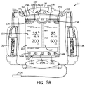
- FIGS. 5A & 5B are perspective views of a multi-channel medical device in communication with a machine-readable input device, in accordance with the present invention.
- FIG. 5A illustrates an infusion pump with a split screen display, having one portion associated with each channel.
- FIG. 5B illustrates an infusion pump with a screen display for receiving infusion programmable input from a user.
- the medical device 14 in this example is a multi-channel infusion pump.
- the medical device 14 can be a single channel infusion pump, a multi-channel infusion pump (as shown), a combination thereof, or the like, as desired for a particular application.
- the medical device 14 provides a machine-readable input device 130.
- the machine-readable input device 130 communicates with the medical device 14 to input machine-readable information to the medical device 14.
- the machine-readable input device 130 can communicate, directly or indirectly, with the medical device 14 via a wireless or hard-wired connection.
- the machine-readable input device 130 can be a device that is separate from but associated or in communication with the medical device 14.
- the machine-readable input device 130 can be any sort of data input means, including those adapted to read machine-readable indicia, such as a barcode scanner or handheld personal digital assistant (PDA).
- PDA personal digital assistant
- the machine-readable input device 130 can be operable to read in other known forms of machine-readable information, such as radio frequency identification tags (RFID), touch memory, digital photography, biometrics, etc.
- RFID radio frequency identification tags
- the medical device 14 is a multi-channel pump having a first channel 132 with first channel machine-readable label 134 and a second channel 136 with a second channel machine-readable label 138.
- a user of the medical device 14 operates the machine-readable input device 130 to select a channel from one or more channels 132 and 136, by scanning in the associated machine-readable label 134 or 138.
- the user selects the desired channel 132 or 136 by using the machine-readable input device 130 to scan a factory or hospital programmed, unique, machine-readable label 134 or 138 that is electronically generated and presented on the screen 122, preferably positioned near the respective channel 132 or 136.
- the machine-readable labels 134 and 138 are physically affixed to the medical device 14, preferably on or positioned near the channel 132 and 136, respectively. Since the machine-readable labels 134 and 138 are generated and/or can be stored in memory 124 by the medical device 14, the medical device 14 can associate the machine-readable labels 134 and 138 to the channels 132 or 136.
- the medical device 14 then allows the user to program and activate the selected channel 132 or 136.
- the user may also manually select the desired channel by touching an appropriate folder tab on the touch screen.
- the folder tabs are labeled and/or physically arranged on the screen so as to be proximate to the corresponding channel 132 or 136.
- all the medical devices can periodically broadcast a unique wireless device/channel IP address and/or a self-generated unique machine-readable label (for example, a barcode) 134 or 138 that can also be presented on the screen 122.
- a self-generated unique machine-readable label for example, a barcode
- the machine-readable labels 134 and 138 are physically affixed to or posted on the medical device 14.
- Each medical device will correlate such broadcasted or posted device/channel IP addresses and/or barcodes with a particular patient, who is also identified by a unique machine readable label (not shown) or patient IP address.
- the user associates the desired pump(s) or channel(s) 132, 136 with the patient by using the machine-readable input device 130 to scan the unique machine-readable labels 134, 138 and the patient's machine readable label.
- This causes the appropriate pump processor(s) 118 to associate the appropriate pump channel(s) 132, 136 with the patient. Then the pumps or channels can associate, communicate, and coordinate with each other wirelessly.
- FIG. 5A illustrates a multi-channel infusion medical device 14 with a split touch screen 122 having a first channel screen portion 140 associated with first channel 132 and a second channel screen portion 142 associated with the second channel 136.
- Each channel screen portion 140 and 142 presents a subset of the delivery information regarding the respective channels 132 or 136 including without limitation therapeutic agent name, concentration, dose rate, VTBI, and alarm information, in a font size that it is easily readable by a user from a distance such as, for example, from approximately fifteen to twenty feet (4.6-6.2 meters) away. This is what is defined herein as a "far view" delivery screen.
- the far view delivery screens display subsets of the information found on the relevant "near view” delivery screens.
- the near view delivery screen displays information such as, drug name, concentration, dose rate, time remaining, VTBI, volume remaining, and alarm name for the highest priority alarm if in an alarm state.
- the delivery screen displays a near view when the user is programming the device as illustrated by FIG. 5B .
- the near view delivery screen will switch to the far view delivery screen after a predetermined period of time that is predetermined by the manufacturer, configurable by the facility via the drug library, and/or set by the caregiver at the pump, for example after 20 seconds. Often, the user does not want to wait for the predetermined length of time to view the far screen.
- the channel screen portion 140 or 142 selected or corresponding to the tab selected expands in area but the size of at least some of the text therein is shrunk.
- the shrinkage of one of the channel screen portions 140 and 142 and enlargement of its counterpart provides additional space for one or more data display or data entry fields to be placed on screen 122, as shown in FIG. 5B .
- data displays or data entry fields are placed on screen 122 in space previously occupied by portions of the channel screen portion 140 or 142.
- This reallocation of space on screen 122 permits the user to enter inputs more easily since the data entry field can be large, preferably at least as large or, more preferably, larger in area than the original channel screen portions 140 and 142 were in the delivery screen mode. Additionally, the reallocation of space on screen 122 provides greater space for presenting information on the channel being adjusted or monitored.
- the medical device 14 includes dedicated or fixed tactile infuser buttons, and images of buttons on the LCD-touch screen 122.
- the fixed tactile buttons 133, 135, 137 , and 139 provide the following functions: LOAD/EJECT button 133 --opens and closes the cassette carriage; ON/OFF button 135 --turns power on and off; ALARM SILENCE button 137 --silences a silenceable alarm for a specified period of time, for example two minutes; and EMERGENCY STOP button 139 --stops all channels.
- the LCD color touch screen 122 allows the user to access and use on-screen button images, for example 3 D button images, and data entry fields.
- the touch screen 122 uses a membrane over the LCD display so a single keypress does not cause significant infusion pole movement nor is it mistaken for a double keypress.
- the touch screen also accommodates a keypress whether the user is wearing wet gloves, dry gloves, or no gloves.
- LCD touch screen button images 143, 145, 147, and 149A-149E are located as shown in FIGS. 5A & 5B perform the following functions: Patient Information Tab 143 --displays the clinical care area, preselected patient information (including without limitation name, ID number, etc.), and provides access to a more detailed patient information screen; Channel Level Therapy Buttons 145 --accessed by button images on the infuser touch screen, are used to select an infusion therapy; Program Level Buttons 147 --accessed by pressing areas, drop-down list triangles, boxes or text boxes on the programming screen, are used to select dose parameters of an infusion; and Device Level Buttons 149A-149E at the bottom of the touch screen are used to display and control device level features, including without limitation Mode 149A (for example, Operational or Biomed), Logs 149B, Locks 149C, Settings 149D, and Calculator display 149E.
- a wireless indicator image 102 displayed at the bottom of the screen 122 indicates that the medical device 14 is connected and ready for communication.
- the healthcare practitioner can program each individual channel of the pump with specific fluid therapies in a variety of weight- and body surface area-based units such as micrograms/kg/hour, grams/m 2 /hr, and other delivery specifications for the following modes:
- Bolus delivery allows user to program a single uninterrupted discrete delivery based on dose amount and time (the bolus can be delivered from the primary or a secondary container);
- Advanced Programming mode provides various types of programs including: Multistep--which allows a sequential delivery of fluid in up to 10 steps, with fluid volumes and delivery rates programmable for each step based on Rate and Volume or Volume and Time; Variable Time--which allows up to 24 dose calculation steps at specified clock times; Intermittent--a calculated dose or step to be delivered at regular intervals; and Taper--a delivery that ramps up and/or ramps down to a plateau rate.
- the graphical user interface 126 provides channel indicators presented on screen 122.
- the channel indicators associate on-screen programming, delivery, and alarm information with a particular delivery channel by using graphical depictions such as a channel indication icon 154, 155.
- the channel indication icon 154 or 155 is a graphical item clearly associating on-screen programming, delivery, and alarm information with a specified associated delivery channel.
- the channel indication icons 154 and 155 are located on a tab 158 associated with a specified delivery channel of the medical device
- the channel indication icon 154 or 155 may include but is not limited to a user readable letter or number, a machine-readable indicator 134, or a combination thereof.
- the graphical user interface program 126 also provides a drip indicator icon 160 and an infusion status icon 156 presented on screen 122.
- the screen 122 provides an optional drop-down box 170 for setting an Allow Rate Catch-Up flag to one of an Enabled setting and a Disabled setting at the pump.
- the drop-down box 170 allows the user to enable or disable the rate catch-up function and to override the default rate catch-up flag provided in the drug library, if desired.
- the Allow Rate Catch-Up flag is set to the Enabled setting, the user can enter a catch-up rate factor in the catch-up rate factor value box 172.
- the screen 122 also displays a catch-up rate factor limit value 174 and a catch-up rate factor alarm value 176 provided through the drug library.
- the catch-up rate factor limit value 174 is the maximum catch-up rate factor which the user can enter in the catch-up rate factor value box 172, i.e., the maximum catch-up rate factor or hard limit allowed for the particular therapeutic agent.
- the catch-up rate factor alarm value 176 is a soft limit on the catch-up rate factor.
- the screen 122 will provide an alarm when the user enters a value in the catch-up rate factor value box 172 which exceeds the catch-up rate factor alarm value 176, but the infusion pump will accept the catch-up rate factor after the user acknowledges the alarm or indicates a decision to override the soft limit as long as the catch-up rate factor does not exceed the hard limit or catch-up rate factor limit value 174.
- catch-up rate factor limit value 174 and the catch-up rate factor alarm value 176 can be omitted or set to a high value as desired for a particular application.
- the default values for the Allow Rate Catch-Up flag setting, catch-up rate factor value box 172, catch-up rate factor limit value 174, and/or catch-up rate factor alarm value 176 can be loaded into the infusion pump from a remote computer as part of a drug library editing program such as HOSPIRA MEDNETTM software.
- the default values for the Allow Rate Catch-Up flag, catch-up rate factor value box 172, catch-up rate factor limit value 174, and/or catch-up rate factor alarm value 176 can be loaded into the infusion pump by the user at the infusion pump.
- the default values can be established in a drug library downloaded to the pump and, if allowed by a setting in the drug library, later overridden or modified by the user at the pump.
- the entire catch-up rate behavior can be predetermined by the manufacturer and hard coded into the pump, without any user customization being allowed.
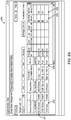
- FIGS. 6A & 6B are screen shots of a graphical user interface and detail of the graphical user interface, respectively, for configuring a drug library, in accordance with the present invention.
- the graphical user interface 200 can be displayed on the display/input device 38 of the MMU 12 (as shown in FIG. 2 ) and used to receive data for creating or updating the drug library, such as the catch-up rate factor, Allow Rate Catch-up flag setting, maximum catch-up rate factor setting, maximum catch-up rate factor alarm setting, and the like.
- the graphical user interface 200 includes a table 201 to receive different drugs and therapeutic agents in the drug library database.
- Drug list 202 includes a list of the names of the drugs in the drug library, which could be the generic names, brand names or both.
- the drug list can include multiple entries for the same drug but different concentrations or clinical uses (cardiac, renal, pediatric).
- the Allow Rate Catch-Up Flag list 204 includes the allow rate catch-up flag setting for each drug/concentration/use entry ("drug entry" for short) in the drug list 202 to determine whether rate catch-up is allowed for the particular drug entry.
- the Allow Rate Catch-up flag setting can be a function of pump type and/or clinical care area location.
- the maximum rate catch-up list 206 includes the maximum catch-up rate factor setting for each drug entry in the drug list 202 for which rate catch-up is allowed.
- the maximum catch-up rate factor setting also can be a function of pump type and clinical care area location.
- allowable maximum catch-up rate factors are regular linear percentages at predetermined intervals, e.g., 5%, 10%, 15%, 20%, et cetera.
- the table 201 can also include other parameters that constrain or limit the drug maximum catch-up rate such as the normal global constraints on rate already configured via the MMU 12 and HOSPIRA MEDNETTM software (Lower Hard Limit, Lower Soft Limit, Upper Soft Limit, and/or Upper Hard Limit).
- the maximum catch-up rate factor alarm setting and other drug maximum catch-up rate limits for each drug entry also can be a function of pump type and clinical care area location.
- the catch-up rate factor is a simple percentage applied to the desired infusion rate to obtain a catch-up infusion rate when the actual accumulated infusion volume is less than the expected accumulated infusion volume.
- the desired infusion rate is input directly as a rate or volume per unit of time, such as mL/hr.
- the desired infusion rate is a calculated value based upon a dose and the weight or body surface area of the patient. For example, a dose of 10 mL/kg/hr can be prescribed for a patient who weighs 100 kg. Thus, the desired infusion rate would be calculated as 1000 mL/hr. In other cases the desired infusion rate is calculated based upon the dose and concentration of drug in the container.
- the desired infusion rate is calculated at 100 mL/hr.
- the catch-up rate factor is added to the desired infusion rate.
- the catch-up rate factor (for example 1.05) is multiplied by the desired infusion rate.
- allowable catch-up rate factors are regular linear percentages at predetermined intervals, e.g., 5%, 10%, 15%, 20%, et cetera to make it easier for the user to select a catch-up rate factor.
- the catch-up rate factor applies a linear adjustment to the desired infusion rate and does not rely on any input from physiological factors of the patient.
- the configurable closed loop delivery rate catch-up is straightforward and does not rely on complex algorithms or control schemes. Instead the feedback mechanism of this algorithm is based only on the measured versus expected accumulated volume delivered over time by the pump.
- the new rate Y is determined by a simple single order equation X + AX or AX; where A equals the catch-up rate factor as described above.
- the Allow Rate Catch-up flag setting as a function of pump type can account for different pump types, makes and models, as well as uses for which various pump types are employed.
- one pump type using a cartridge and driving a plunger with a stepper motor can be used for general infusion such as saline solutions or the like, so that there is little risk in allowing rate catch-up.
- another pump type using a prefilled syringe can be used for analgesics or opiates, so that it may not be desirable to allow rate catch-up.
- Other pump types may have multiple uses or therapies and it may be desirable to control the enablement of the catch-up rate feature for each of the plurality of uses available with such a pump type.
- the Allow Rate Catch-up flag setting can be a function of clinical care area location.
- an infusion pump used in a treatment area in which the patients are in serious or critical condition such as an emergency or operating room, may not want to allow rate catch-up.
- an infusion pump used in a treatment area in which the patients are in good condition may want to allow rate catch-up.
- the table 201 can also include other data as desired for a particular application.
- the table 201 can include other exemplary columns 208 for additional data for the different drugs, such as External Drug ID Numbers, Drug Display Names, Drug Concentration/Container Volume, Selected Drug Rule Set (Label Only, Limited, Full), Drug Dosing Unit, Drug Dosing Limits (Lower Hard Limit, Lower Soft/Alarm Limit, Upper Soft/Alarm Limit, and/or Upper Hard Limit) or the like.
- the drug library provides flexibility for various combinations of parameters as desired for a particular application.
- the drug library can have different Allow Rate Catch-up flag settings for different drugs or drug entries in the drug library.
- the drug library can have different maximum permissible catch-up rate factor settings for different drugs in the drug library.
- the drug library can have a given drug listed in multiple different clinical care areas (CCAs) in the drug library with at least one of different Allow Rate Catch-up flag settings and different maximum catch-up rate factor settings for a the given drug.
- CCAs clinical care areas
- FIG. 7 is a graph of an infusion volume and infusion rate versus time modeled for an infusion with an infusion pump employing configurable closed loop delivery rate catch-up, in accordance with the present invention.
- the graph 300 includes the expected accumulated infusion volume 310, the actual accumulated infusion volume 320, and the infusion rate 330.
- the expected accumulated infusion volume 310 increases linearly at a desired infusion rate of 100 mL per hour.
- the actual accumulated infusion volume 320 increases linearly from time 0:00 until time 1:00 at the originally programmed or desired infusion rate 330 of 100 mL per hour.
- the infusion is interrupted so that the infusion rate 330 remains approximately zero and the actual accumulated infusion volume 320 remains about 100 mL until time 1:15, when the infusion resumes.
- the actual accumulated infusion volume 320 is less than the expected accumulated infusion volume 310, so the infusion rate is increased by the catch-up rate factor of 15% and the infusion resumes at a catch-up infusion rate of 115 mL per hour from time 1:15 to time 2:00.
- the actual accumulated infusion volume 320 has not quite yet caught up with the expected accumulated infusion volume 310 and the infusion is once again interrupted.
- the infusion rate 330 remains approximately zero and the actual accumulated infusion volume 320 remains about 200 mL until time 2:10, when the infusion resumes. From time 2:10 until time 3:20, the infusion is delivered at the catch-up infusion rate of 115 mL per hour until the actual accumulated infusion volume 320 equals the expected accumulated infusion volume 310 at time 3:20, when the infusion rate 330 is reduced to the originally programmed or desired infusion rate of 100 mL per hour.
- the infusion is once again interrupted so that the infusion rate 330 remains approximately 0 and the actual accumulated infusion volume 320 remains at about 375 mL until the infusion resumes at time 3:55.
- the infusion is delivered at the catch-up infusion rate of 115 mL per hour until the actual accumulated infusion volume 320 equals the expected accumulated infusion volume 310 at time 4:40, when the infusion rate 330 is reduced to the originally programmed or desired infusion rate of 100 mL per hour.
- the desired accumulated volume of 500 mL has been delivered by the scheduled time 5:00 in spite of three interruptions in the infusion.
- FIG. 8 is a block diagram of a control model for an infusion pump employing configurable closed loop delivery rate catch-up, in accordance with the present invention.
- the control model 400 includes an infusion volume calculator 410, a volume comparator 420, a pump controller 430, a pump drive 440, and a flow integrator 450.
- the infusion volume calculator 410 receives a desired infusion rate signal 412 and generates an expected accumulated infusion volume signal 414 from the originally programmed desired infusion rate signal 412 and the elapsed time.
- the volume comparator 420 receives the expected infusion volume signal 414 and an actual accumulated infusion volume signal 452, and generates a volume error signal 422 from the expected accumulated infusion volume signal 414 and the actual accumulated infusion volume signal 452.
- the pump controller 430 also receives the desired infusion rate signal 412 and the accumulated volume error signal 422, and generates a pump drive signal 432 from the desired infusion rate signal 412 and the accumulated volume error signal 422.
- the pump drive 440 receives the pump drive signal 432 to deliver the infusion 442.
- the pump drive 440 is subject to disturbances 444 which can cause or result in interrupted delivery of the infusion 442.
- the disturbance may include but are not limited to stoppages due to alarms, occlusions and other faults.
- the flow integrator 450 is operable to monitor the pump drive 440 and/or the infusion 442 and generate the actual accumulated infusion volume signal 452.
- the pump drive 440 moves the plunger in a syringe and the flow integrator 450 senses pump drive/plunger position.
- the pump drive 440 is a stepper motor and the flow integrator 450 counts pump strokes or motor steps.
- the pump drive 440 is a rotary pump and the flow integrator 450 counts pump rotations.
- the present invention could also be applied with a drip counting device to provide the necessary feedback concerning the actual flow rate and/or accumulated volume.
- the pump drive signal 432 is a function of the desired infusion rate signal 412 multiplied by a catch-up rate factor when the volume error signal 422 meets (equals and/or exceeds) a threshold that indicates that actual accumulated infusion volume is less than expected accumulated infusion volume, to catch up interrupted delivery of an infusion.
- the pump drive signal 432 is a function of the desired infusion rate signal 412 alone or returns to the originally programmed or set rate when the accumulated volume error signal 422 indicates that the actual accumulated infusion volume is greater than or equal to the expected accumulated infusion volume.
- FIG. 9 is a flowchart of a method for configuring a drug library for use with an infusion system employing configurable closed loop delivery rate catch-up, in accordance with the present invention.
- the method 500 includes providing a graphical user interface 502 for modifying a drug library of the medication management unit; receiving a catch-up rate factor on the graphical user interface 504; updating the drug library with the catch-up rate factor 506; and transmitting the updated drug library to a memory of an infusion pump 508.
- the method 500 can be performed on a medication management unit having a processing unit and a storage medium coupled to the processing unit, the storage medium containing programming code executable by the processing unit to perform the steps of the method 500.
- the drug library can include additional settings for a method for configuring a drug library for use with an infusion system employing configurable closed loop delivery rate catch-up as desired for a particular application.
- the drug library can further include an Allow Rate Catch-up flag setting having one of an Enabled setting and a Disabled setting, the Allow Rate Catch-up flag setting being a function of a parameter selected from the group consisting of drug/concentration/use entry, pump type, and clinical care area location.
- the drug library can further include a maximum catch-up rate factor setting having a numerical value, the maximum catch-up rate factor setting being a function of a parameter selected from the group consisting of drug entry, pump type and clinical care area location.
- the drug library can further include a maximum catch-up rate factor alarm setting having a numerical value, the maximum catch-up rate factor alarm setting being a function of a parameter selected from the group consisting of drug entry, pump type and clinical care area location.
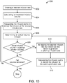
- FIG. 10 is a flowchart of a method for operating an infusion pump employing configurable closed loop delivery rate catch-up, in accordance with the present invention.
- the method 600 includes entering a desired infusion rate 602 for the infusion pump; calculating an expected accumulated infusion volume 604 as a function of time from the infusion rate; requesting the infusion pump to deliver the infusion at the desired infusion rate 606; determining an actual accumulated infusion volume 608 at a particular time; and determining whether the actual accumulated infusion volume is less than the expected accumulated infusion volume 609.
- the method 600 continues with increasing the desired infusion rate by a catch-up rate factor to generate a catch-up infusion rate 610 and requesting the infusion pump to deliver the infusion at the catch-up infusion rate 612.
- the method 600 continues monitoring the output of the pump and with delivering the infusion at the originally programmed or desired infusion rate.
- the method 600 can also request the infusion pump to deliver the infusion at the originally programmed or desired infusion rate after delivery of the infusion at the catch-up infusion rate 612 when the actual accumulated infusion volume is equal to the expected accumulated infusion volume.
- the method 600 continues by determining whether the full accumulated volume prescribed or programmed has been delivered or not. The method 600 stops if the full volume has been delivered, or loops back to continue with step 606 if more volume remains to be delivered.
- the method 600 can also allow the user at the infusion pump to provide input.
- the method 600 can include a user at the infusion pump inputting an Allow Rate Catch-up flag setting to a Disabled setting to disable the increasing and the delivery rate catch-up function.
- the method 600 can include the user at the infusion pump inputting the catch-up rate factor to a desired value.
- the catch-up rate factors are regular linear percentages at predetermined intervals, e.g., 5%, 10%, 15%, 20%, et cetera.
- the drug library editor or the pump may allow the user more flexibility to customize the values and the intervals between them.
- the method 600 may or may not require user action before applying the catch-up infusion rate if desired for a particular application.
- the requesting the infusion pump to deliver the infusion at the catch-up infusion rate 612 can occur automatically, without user action, by increasing the desired infusion rate by a catch-up rate factor to generate a catch-up infusion rate 610.
- the method 600 can include annunciating an alarm or warning before increasing the desired infusion rate by a catch-up rate factor to generate a catch-up infusion rate 610, and requiring the user acknowledge the alarm and confirm that the catch-up rate behavior is desired before the requesting the infusion pump to deliver the infusion at the catch-up infusion rate 612.
- the method 600 can include annunciating an alarm or warning after increasing the desired infusion rate by a catch-up rate factor to generate a catch-up infusion rate 610, and allowing the user to confirm or reject the catch-up rate behavior. If the catch-up rate behavior is rejected, the infusion will revert to the originally programmed infusion rate.
- the method 600 can also provide limits and alarms in response to user input.
- the method 600 further includes rejecting the input catch-up rate factor when the desired value is greater than a maximum catch-up rate factor setting.
- the method 600 further includes providing an alarm when the desired value is greater than a maximum catch-up rate factor alarm setting.
- the increasing the desired infusion rate by a catch-up rate factor in the method 600 includes receiving an alarm when at the particular time the actual accumulated infusion volume is less than the expected accumulated infusion volume; and acknowledging the alarm prior to increasing the desired infusion rate by a catch-up rate factor to generate a catch-up infusion rate.
- the method 600 can be performed on an infusion pump having a processor and the memory coupled to the processor, the memory containing programming code executable by the processor to perform the steps of the method 600.
- the infusion pump 14 can be in electronic communication with a medication management unit 12 and the catch-up rate factor can be part of an updated drug library transmitted from the medication management unit 12 and received at the medical device 14.
Description
- The present invention relates to medical devices. More specifically, the invention relates to infusion systems and pumps with configurable closed loop delivery rate catch-up.
- Infusion pumps are medical devices that deliver fluids, including nutrients and medications such as antibiotics, chemotherapy drugs, and pain relievers, into a patient's body in controlled amounts. Many types of pumps, including large volume, patient-controlled analgesia (PCA), elastomeric, syringe, enteral, and insulin pumps, are used worldwide in healthcare facilities such as hospitals, and in the home. Clinicians and patients rely on pumps for safe and accurate administration of fluids and medications.
- Presently available infusion pumps use an open loop pumping rate: the desired pumping or volumetric flow rate is input directly, or calculated from an input volume to be infused and delivery period or duration, and the infusion pump operates at a single target motor speed or stroke frequency to deliver the desired pumping or flow rate regardless of external conditions. Unfortunately, flow delivery can be interrupted by a variety of conditions, such as a stoppage or pause based upon a full or partial occlusion, a kinked tube, an air-in-line alarm, hanging a new IV bag, vein clot, or the like. Once the flow delivery is interrupted, the time in which there is no medication delivery is lost, resulting in a delay in desired infusion completion.
- Nurses typically work in shifts and expect certain medications to be started and/or finished within their shift and plan accordingly. When occlusions, pauses, or other disturbances interrupt or delay medication delivery, this disrupts the nurses' planning for patient care within their respective shifts. In addition, the patients in these scenarios would not receive the medicine required within the allotted time.
-
US 5,522,798 discloses a host controller to controls drug concentrations for each of a plurality of channels delivered through multiple drug channels of a multi-channel drug delivery system. The host controller includes a controller that is coupled to each drug channel of the multichannel drug delivery system to receive actual drug delivery rate information. -
US 4,525,163 discloses a controller for an intravenous set which operates both to maintain the instantaneous drip rate through a drip chamber included in the IV set at a desired value, and to modify this value repeatedly during the course of an infusion. The desired drip value is modified in accordance with the measured volumetric flow rate through the intravenous set such that if a particular infusion fluid produces abnormally small volume drops in the drip chamber, then the controller automatically increases the drip rate to compensate. -
US 2006/0270971 discloses a patient hydration system including an infusion device for administering hydration fluid to a patient and a patient urine output measurement device. If a disruption is detected, a controller software calculates an amount of urine made by a patient during the disruption using weight measurements, and the system increases the infusion rate. -
US 2002/0077852 discloses a system for creating a customized drug library for an electronically loadable drug infusion pump, the system including a drug library containing a plurality of drug entries, there being associated with each drug entry a set of associated drug delivery parameters and/or drug delivery protocols for configuring the drug infusion pump. -
US 2006/0064053 discloses an infusion system comprising a first pump device that delivers a first infusate to an IV infusion line and a second pump device that delivers a second infusate to the IV line. A measurement device determines an amount of undelivered first infusate remaining in a receptacle. A control system communicates with the first and second delivery devices and the measurement device to determine an optimum first infusate infusion flow rate based on the determined amount of undelivered first infusate remaining in the system, a predetermined volume of fluid to be infused, and a predetermined infusion time period. - It would be desirable to have an infusion system and pump with configurable closed loop delivery rate catch-up that would overcome the above disadvantages.
- The scope of the invention is defined by the appended claims. Embodiments and examples not falling within the scope of the claims are for reference only.
- Other features and advantages of the invention will become further apparent from the following detailed description of the presently preferred embodiments, read in conjunction with the accompanying drawings. The detailed description and drawings are merely illustrative of the invention rather than limiting, the scope of the invention being defined by the appended claims.
-
-
FIG. 1 is a schematic diagram of the medication management system including a medication management unit and a medical device integrated with other systems in a hospital environment, in accordance with the present invention; -
FIG. 2 is a schematic diagram of the medication management unit, in accordance with the present invention; -
FIG. 3 is a schematic diagram of some of the major functions performed by the medication management unit, in accordance with the present invention; -
FIG. 4 is a schematic diagram of a medical device, in accordance with the present invention; -
FIGS. 5A &5B are perspective views of a multi-channel medical device, in accordance with the present invention; -
FIGS. 6A &6B are screen shots of a graphical user interface and detail of the graphical user interface, respectively, for configuring a drug library, in accordance with the present invention; -
FIG. 7 is a graph of an infusion volume and infusion rate versus time modeled for an infusion with an infusion pump employing configurable closed loop delivery rate catch-up, in accordance with the present invention; -
FIG. 8 is a block diagram of a control model for an infusion pump employing configurable closed loop delivery rate catch-up, in accordance with the present invention; -
FIG. 9 is a flowchart of a method for configuring a drug library for use with an infusion system employing configurable closed loop delivery rate catch-up, in accordance with the present invention; and -
FIG. 10 is a flowchart of a method for operating an infusion pump employing configurable closed loop delivery rate catch-up, in accordance with the present invention. -
FIG. 1 is a schematic diagram of the medication management system including a medication management unit and a medical device integrated with an information system, in accordance with the present invention. The medication management system (MMS) 10 includes a medication management unit (MMU) 12 and amedical device 14, typically operating in ahospital environment 16. The term hospital environment as defined herein is used broadly to mean any medical care facility, including but not limited to a hospital, treatment center, clinic, doctor's office, day surgery center, hospice, nursing home, and any of the above associated with a home care environment. There can be a variety of information systems in a hospital environment. As shown inFIG. 1 , theMMU 12 communicates to a hospital information system (HIS) 18 via acaching mechanism 20 that is part of thehospital environment 16. - Those skilled in the art will appreciate that the
caching mechanism 20 is primarily a pass through device for facilitating communication with theHIS 18 and its functions can be eliminated or incorporated into the MMU 12 (FIG. 1 ) and/or themedical device 14 and/or theHIS 18 and/or other information systems or components within thehospital environment 16. Thecaching mechanism 20 provides temporary storage of hospital information data separate from theHIS 18, the medication administration record system (MAR) 22, pharmacy information system (PhIS) 24, physician order entry (POE) 26, and/orLab System 28. Thecaching mechanism 20 provides information storage accessible to themedication management system 10 to support scenarios where direct access to data within thehospital environment 16 is not available or not desired. In one example, thecaching mechanism 20 provides continued flow of information in and out of theMMU 12 in instances where theHIS 18 is down or the connectivity between theMMU 12 and the electronic network (not shown) is down. - The
HIS 18 communicates with a medication administration record system (MAR) 22 for maintaining medication records and a pharmacy information system (PhIS) 24 for delivering drug orders to the HIS. A physician/provider order entry (POE)device 26 permits a healthcare provider to deliver a medication order prescribed for a patient to the hospital information system directly or indirectly via thePhIS 24. One skilled in the art will also appreciate that a medication order can be sent to theMMU 12 directly from the PhIS 24 orPOE device 26. As used herein, the term medication order is defined as an order to administer something that has a physiological impact on a person or animal, including but not limited to liquid or gaseous fluids, drugs or medicines, liquid nutritional products and combinations thereof. -
Lab system 28 andmonitoring device 30 also communicate with theMMU 12 to deliver updated patient-specific information to theMMU 12. As shown, theMMU 12 communicates directly to thelab system 28 and monitoringdevice 30. However, those skilled in the art will appreciate that theMMU 12 can communicate with thelab system 28 and monitoringdevice 30 indirectly via theHIS 18, thecaching mechanism 20, themedical device 14 or some other intermediary device or system. - Delivery
information input device 32 also communicates with theMMU 12 to assist in processing drug orders for delivery through theMMU 12. The deliveryinformation input device 32 can be any sort of data input means, including those adapted to read machine readable indicia such as barcode labels; for example a personal digital assistant (PDA) with a barcode scanner. Hereinafter, the deliveryinformation input device 32 is referred to asinput device 32. Alternatively, the machine readable indicia can be in other known forms, such as radio frequency identification (RFID) tag, two-dimensional bar code, ID matrix, transmitted radio ID code, human biometric data such as fingerprints, etc. and theinput device 32 adapted to "read" or recognize such indicia. Theinput device 32 is shown as a separate device from themedical device 14; alternatively, theinput device 32 communicates directly with themedical device 14 or can be integrated wholly or in part with the medical device. -
FIG. 2 is a schematic diagram of the medication management unit, in accordance with the present invention. Themedication management unit 12 includes anetwork interface 34 for connecting theMMU 12 to multiple components of ahospital environment 16, one or moremedical devices 14, and any other desired device or network. Aprocessing unit 36 is included inMMU 12 and performs various operations described in greater detail below. A display/input oruser interface device 38 communicates with theprocessing unit 36 and allows the user to receive output from processingunit 36 and/or input information into theprocessing unit 36. Those skilled in the art will appreciate that the display/input device 38 can be provided as a separate display device and a separate input device. - An electronic storage medium 40 communicates with the
processing unit 36 and stores programming code and data necessary for theprocessing unit 36 to perform the functions of theMMU 12. More specifically, the storage medium 40 stores multiple programs formed in accordance with the present invention for various functions of theMMU 12 including but not limited to the following programs: MaintainDrug Library 42; Download Drug Library 44;Process Drug Order 46; Maintain ExpertClinical Rules 48; Apply ExpertClinical Rules 50; Monitor Pumps 52;Monitor Lines 54; GenerateReports 56;View Data 58; Configure the MMS 60; and Monitor theMMS 62. The MaintainDrug Library 42 program creates, updates, and deletes drug entries and establishes a current active drug library. The Download Drug Library 44 program updatesmedical devices 14 with the current drug library. TheProcess Drug Order 46 program processes the medication order for a patient, verifying that the point of care (POC) medication and delivery parameters match those ordered. The Maintain ExpertClinical Rules 48 program creates, updates, and deletes the rules that describe the hospital's therapy and protocol regimens. The Apply ExpertClinical Rules 50 program performs logic processing to ensure safety and considers other infusions or medication orders, patient demographics, and current patient conditions. The Monitor Pumps 52 program acquires ongoing updates of status events, and alarms transmitted both near real-time and in batch mode, as well as tracking the location, current assignment, and software versions such as the drug library version residing onmedical device 14. TheMonitor Lines 54 program acquires ongoing updates of status, events and alarms for each channel or line for amedical device 14 that supports multiple drug delivery channels or lines. The Generate Reports 56 program provides a mechanism that allows the user to generate various reports of the data held in the MMU storage medium 40. TheView Data 58 program provides a mechanism that supports various display or view capabilities for users of theMMU 12. TheNotifications 59 program provides a mechanism for scheduling and delivery of events to external systems and users. The Configure the MMS 60 program provides a mechanism for system administrators to install and configure theMMS 10. The Monitor theMMS 62 program enables information technology operations staff capabilities to see the current status ofMMS 10 components and processing, and other aspects of day-to-day operations such as system start up, shut down, backup and restore. -
FIG. 3 is a schematic diagram of some of the major functions performed by the medication management unit, in accordance with the present invention. The various functional programs 42-62 of theMMU 12, each including separate features and rules, are partitioned (at a higher level than shown inFIG. 2 ) and logically organized into interrelated managing units of theMMU 12. As shown, theMMU 12 includes an asset manager 64, analarm manager 66, a drug library manager (such as, for example, is included in HOSPIRA MEDNET™ software) 68, acaregiver manager 70, atherapy manager 72, and/or aclinical data manager 73. However, those skilled in the art will appreciate that additional or alternative hospital system managing units can be provided without departing from the present invention. Additionally, theMMU 12 includes amaster adjudicator 74 between the separate interrelated managing units 64-73 of theMMU 12, to regulate the interaction between the separate management units. - Further, while the
MMU 12 as described herein appears as a single device, there can be more than oneMMU 12 operating harmoniously and sharing the same database. For example theMMU 12 can consist of a collection of MMU specific applications running on distinct servers in order to avoid a single point of failure, address availability requirements, and handle a high volume of requests. In this example, each individual server portion of theMMU 12 operates in conjunction with other server portions of theMMU 12 to redirect service requests to another server portion of theMMU 12. Additionally, themaster adjudicator 74 assigns redirected service requests to another server portion of theMMU 12, prioritizing each request and also ensuring that each request is processed. - With reference to
FIGS. 2 &3 , the managing units 64-72 each include separate features and rules to govern their operation. For example, the asset manager 64 governs the execution of the Monitor Pumps 52 andMonitor Lines 54 programs; thedrug library manager 68 governs the execution of theDrug Library 42 and Download Drug Library 44 programs; thetherapy manager 72 governs the execution of theProcess Drug Order 46, Maintain ExpertClinical Rules 48, and Apply ExpertClinical Rules 50 programs; and theclinical data manager 73 governs the execution of the GenerateReports 56 andView Data 58 programs. Other distribution of the functional MMU programs 42-62 among the managing units 64-73 can be made in accordance with the present invention. -
FIG. 4 is a schematic diagram of a medical device, in accordance with the present invention. Anelectronic network 114 connects theMMU 12,medical device 14, andhospital environment 16 for electronic communication. Theelectronic network 114 can be a completely wireless network, a completely hard wired network, or some combination thereof. As used herein, the term "medical device" includes without limitation a device that acts upon a cassette, reservoir, vial, syringe, or tubing to convey medication or fluid to or from a patient (for example, an enteral pump, a parenteral infusion pump, a patient controlled analgesia (PCA) or pain management medication pump, or a suction pump), a monitor for monitoring patient vital signs or other parameters, or a diagnostic, testing or sampling device. - The pump style
medical device 14 includes anetwork interface 112 for connecting themedical device 14 toelectronic network 114. Where a wireless connection to theelectronic network 114 is desired,network interface 112 operates an antenna for wireless connection to theelectronic network 114. The antenna can project outside themedical device 14 or be enclosed within the housing of the device. - A
processor 118 is included in themedical device 14, includes a real time clock (not shown), and performs various operations described in greater detail below. The input/output device 120 allows the user to receive output from themedical device 14 and/or input information into themedical device 14. - Those skilled in the art will appreciate that input/
output device 120 can be provided as a single device such as atouch screen 122, or as a separate display device and a separate input device (not shown). In one embodiment, thedisplay screen 122 of themedical device 14 is a thin film transistor active matrix color liquid crystal display with a multi-wire touch screen. A membrane generally impermeable to fluids overlays thedisplay screen 122 so the user can press images of keys or buttons on the underlying screen with wet gloves, dry gloves, or without gloves to trigger an input. - A
memory 124 communicates with theprocessor 118 and stores code and data necessary for theprocessor 118 to perform the functions of themedical device 14. More specifically, thememory 124 stores multiple programs formed in accordance with the present invention for various functions of themedical device 14 including a graphicaluser interface program 126 with multiple subparts described in greater detail below. -
FIGS. 5A &5B are perspective views of a multi-channel medical device in communication with a machine-readable input device, in accordance with the present invention.FIG. 5A illustrates an infusion pump with a split screen display, having one portion associated with each channel.FIG. 5B illustrates an infusion pump with a screen display for receiving infusion programmable input from a user. Themedical device 14 in this example is a multi-channel infusion pump. Those skilled in the art will appreciate that themedical device 14 can be a single channel infusion pump, a multi-channel infusion pump (as shown), a combination thereof, or the like, as desired for a particular application. - Referring to
FIG. 5A , themedical device 14 provides a machine-readable input device 130. The machine-readable input device 130 communicates with themedical device 14 to input machine-readable information to themedical device 14. The machine-readable input device 130 can communicate, directly or indirectly, with themedical device 14 via a wireless or hard-wired connection. The machine-readable input device 130 can be a device that is separate from but associated or in communication with themedical device 14. The machine-readable input device 130 can be any sort of data input means, including those adapted to read machine-readable indicia, such as a barcode scanner or handheld personal digital assistant (PDA). Alternatively, the machine-readable input device 130 can be operable to read in other known forms of machine-readable information, such as radio frequency identification tags (RFID), touch memory, digital photography, biometrics, etc. - The
medical device 14 is a multi-channel pump having afirst channel 132 with first channel machine-readable label 134 and asecond channel 136 with a second channel machine-readable label 138. A user of themedical device 14 operates the machine-readable input device 130 to select a channel from one ormore channels readable label - The user selects the desired
channel readable input device 130 to scan a factory or hospital programmed, unique, machine-readable label screen 122, preferably positioned near therespective channel readable labels medical device 14, preferably on or positioned near thechannel readable labels memory 124 by themedical device 14, themedical device 14 can associate the machine-readable labels channels medical device 14 then allows the user to program and activate the selectedchannel corresponding channel - In a further aspect of the wireless embodiment, all the medical devices can periodically broadcast a unique wireless device/channel IP address and/or a self-generated unique machine-readable label (for example, a barcode) 134 or 138 that can also be presented on the
screen 122. Alternatively, the machine-readable labels medical device 14. Each medical device will correlate such broadcasted or posted device/channel IP addresses and/or barcodes with a particular patient, who is also identified by a unique machine readable label (not shown) or patient IP address. The user associates the desired pump(s) or channel(s) 132, 136 with the patient by using the machine-readable input device 130 to scan the unique machine-readable labels - The graphical user interface program reallocates
screen 122 for themedical device 14. Specifically,FIG. 5A illustrates a multi-channel infusionmedical device 14 with asplit touch screen 122 having a firstchannel screen portion 140 associated withfirst channel 132 and a secondchannel screen portion 142 associated with thesecond channel 136. Eachchannel screen portion respective channels - In practice, the delivery screen displays a near view when the user is programming the device as illustrated by
FIG. 5B . The near view delivery screen will switch to the far view delivery screen after a predetermined period of time that is predetermined by the manufacturer, configurable by the facility via the drug library, and/or set by the caregiver at the pump, for example after 20 seconds. Often, the user does not want to wait for the predetermined length of time to view the far screen. - Returning to
FIG. 5A , thechannel screen portion channel screen portions screen 122, as shown inFIG. 5B . As discussed below, data displays or data entry fields are placed onscreen 122 in space previously occupied by portions of thechannel screen portion screen 122 permits the user to enter inputs more easily since the data entry field can be large, preferably at least as large or, more preferably, larger in area than the originalchannel screen portions screen 122 provides greater space for presenting information on the channel being adjusted or monitored. - Referring again to
FIG. 5A , themedical device 14 includes dedicated or fixed tactile infuser buttons, and images of buttons on the LCD-touch screen 122. The fixedtactile buttons EJECT button 133--opens and closes the cassette carriage; ON/OFF button 135--turns power on and off;ALARM SILENCE button 137--silences a silenceable alarm for a specified period of time, for example two minutes; andEMERGENCY STOP button 139--stops all channels. The LCDcolor touch screen 122 allows the user to access and use on-screen button images, for example 3D button images, and data entry fields. Thetouch screen 122 uses a membrane over the LCD display so a single keypress does not cause significant infusion pole movement nor is it mistaken for a double keypress. The touch screen also accommodates a keypress whether the user is wearing wet gloves, dry gloves, or no gloves. - LCD touch
screen button images FIGS. 5A &5B perform the following functions:Patient Information Tab 143--displays the clinical care area, preselected patient information (including without limitation name, ID number, etc.), and provides access to a more detailed patient information screen; Channel Level Therapy Buttons 145--accessed by button images on the infuser touch screen, are used to select an infusion therapy;Program Level Buttons 147--accessed by pressing areas, drop-down list triangles, boxes or text boxes on the programming screen, are used to select dose parameters of an infusion; andDevice Level Buttons 149A-149E at the bottom of the touch screen are used to display and control device level features, including withoutlimitation Mode 149A (for example, Operational or Biomed), Logs 149B,Locks 149C,Settings 149D, andCalculator display 149E. Awireless indicator image 102 displayed at the bottom of thescreen 122 indicates that themedical device 14 is connected and ready for communication. - By using the Channel Level Therapy Buttons 145 and the
Program Level Buttons 147, the healthcare practitioner can program each individual channel of the pump with specific fluid therapies in a variety of weight- and body surface area-based units such as micrograms/kg/hour, grams/m2/hr, and other delivery specifications for the following modes: Basic Therapy--includes dose calculation, which allows dose rate programming based on volume to be infused (VTBI), drug amount, infusion time and drug concentration and simple rate programming that allows programming of volumetric rate (mL/hr) based upon VTBI and time; Bolus delivery ---allows user to program a single uninterrupted discrete delivery based on dose amount and time (the bolus can be delivered from the primary or a secondary container); Piggyback delivery--allows user to program the delivery of a secondary infusion, to be delivered through the same cassette as the primary infusion (the primary infusion is paused until the piggyback VTBI completes); and Advanced Programming. Advanced Programming mode provides various types of programs including: Multistep--which allows a sequential delivery of fluid in up to 10 steps, with fluid volumes and delivery rates programmable for each step based on Rate and Volume or Volume and Time; Variable Time--which allows up to 24 dose calculation steps at specified clock times; Intermittent--a calculated dose or step to be delivered at regular intervals; and Taper--a delivery that ramps up and/or ramps down to a plateau rate. - Referring to
FIGS. 4 &5A , thegraphical user interface 126 provides channel indicators presented onscreen 122. The channel indicators associate on-screen programming, delivery, and alarm information with a particular delivery channel by using graphical depictions such as achannel indication icon channel indication icon channel indication icons tab 158 associated with a specified delivery channel of the medical device Thechannel indication icon readable indicator 134, or a combination thereof. The graphicaluser interface program 126 also provides adrip indicator icon 160 and aninfusion status icon 156 presented onscreen 122. - Referring to
FIG. 5B , thescreen 122 provides an optional drop-down box 170 for setting an Allow Rate Catch-Up flag to one of an Enabled setting and a Disabled setting at the pump. The drop-down box 170 allows the user to enable or disable the rate catch-up function and to override the default rate catch-up flag provided in the drug library, if desired. When the Allow Rate Catch-Up flag is set to the Enabled setting, the user can enter a catch-up rate factor in the catch-up ratefactor value box 172. In this example, thescreen 122 also displays a catch-up ratefactor limit value 174 and a catch-up ratefactor alarm value 176 provided through the drug library. The catch-up ratefactor limit value 174 is the maximum catch-up rate factor which the user can enter in the catch-up ratefactor value box 172, i.e., the maximum catch-up rate factor or hard limit allowed for the particular therapeutic agent. The catch-up ratefactor alarm value 176 is a soft limit on the catch-up rate factor. In one example, thescreen 122 will provide an alarm when the user enters a value in the catch-up ratefactor value box 172 which exceeds the catch-up ratefactor alarm value 176, but the infusion pump will accept the catch-up rate factor after the user acknowledges the alarm or indicates a decision to override the soft limit as long as the catch-up rate factor does not exceed the hard limit or catch-up ratefactor limit value 174. Those skilled in the art will appreciate that the catch-up ratefactor limit value 174 and the catch-up ratefactor alarm value 176 can be omitted or set to a high value as desired for a particular application. In one embodiment, the default values for the Allow Rate Catch-Up flag setting, catch-up ratefactor value box 172, catch-up ratefactor limit value 174, and/or catch-up ratefactor alarm value 176 can be loaded into the infusion pump from a remote computer as part of a drug library editing program such as HOSPIRA MEDNET™ software. In another embodiment, the default values for the Allow Rate Catch-Up flag, catch-up ratefactor value box 172, catch-up ratefactor limit value 174, and/or catch-up ratefactor alarm value 176 can be loaded into the infusion pump by the user at the infusion pump. In another hybrid embodiment, the default values can be established in a drug library downloaded to the pump and, if allowed by a setting in the drug library, later overridden or modified by the user at the pump. In another embodiment, the entire catch-up rate behavior can be predetermined by the manufacturer and hard coded into the pump, without any user customization being allowed. -
FIGS. 6A &6B are screen shots of a graphical user interface and detail of the graphical user interface, respectively, for configuring a drug library, in accordance with the present invention. Thegraphical user interface 200 can be displayed on the display/input device 38 of the MMU 12 (as shown inFIG. 2 ) and used to receive data for creating or updating the drug library, such as the catch-up rate factor, Allow Rate Catch-up flag setting, maximum catch-up rate factor setting, maximum catch-up rate factor alarm setting, and the like. - Referring to
FIGS. 6A &6B , thegraphical user interface 200 includes a table 201 to receive different drugs and therapeutic agents in the drug library database.Drug list 202 includes a list of the names of the drugs in the drug library, which could be the generic names, brand names or both. The drug list can include multiple entries for the same drug but different concentrations or clinical uses (cardiac, renal, pediatric). The Allow Rate Catch-Up Flag list 204 includes the allow rate catch-up flag setting for each drug/concentration/use entry ("drug entry" for short) in thedrug list 202 to determine whether rate catch-up is allowed for the particular drug entry. In addition, the Allow Rate Catch-up flag setting can be a function of pump type and/or clinical care area location. The maximum rate catch-uplist 206 includes the maximum catch-up rate factor setting for each drug entry in thedrug list 202 for which rate catch-up is allowed. The maximum catch-up rate factor setting also can be a function of pump type and clinical care area location. In one embodiment, allowable maximum catch-up rate factors are regular linear percentages at predetermined intervals, e.g., 5%, 10%, 15%, 20%, et cetera. The table 201 can also include other parameters that constrain or limit the drug maximum catch-up rate such as the normal global constraints on rate already configured via theMMU 12 and HOSPIRA MEDNET™ software (Lower Hard Limit, Lower Soft Limit, Upper Soft Limit, and/or Upper Hard Limit). The maximum catch-up rate factor alarm setting and other drug maximum catch-up rate limits for each drug entry also can be a function of pump type and clinical care area location. - The catch-up rate factor is a simple percentage applied to the desired infusion rate to obtain a catch-up infusion rate when the actual accumulated infusion volume is less than the expected accumulated infusion volume. In some cases the desired infusion rate is input directly as a rate or volume per unit of time, such as mL/hr. In other cases the desired infusion rate is a calculated value based upon a dose and the weight or body surface area of the patient. For example, a dose of 10 mL/kg/hr can be prescribed for a patient who weighs 100 kg. Thus, the desired infusion rate would be calculated as 1000 mL/hr. In other cases the desired infusion rate is calculated based upon the dose and concentration of drug in the container. For example, if a dose of 10 mcg/hr is prescribed to be delivered from a 1000 mL container of fluid that has a concentration of 100 mcg of the drug, then the desired infusion rate is calculated at 100 mL/hr. There are other alternative dosing units that are known in the art to provide calculated desired infusion rates. In one embodiment, the catch-up rate factor is added to the desired infusion rate. In another embodiment, the catch-up rate factor (for example 1.05) is multiplied by the desired infusion rate. In one embodiment, allowable catch-up rate factors are regular linear percentages at predetermined intervals, e.g., 5%, 10%, 15%, 20%, et cetera to make it easier for the user to select a catch-up rate factor. The catch-up rate factor applies a linear adjustment to the desired infusion rate and does not rely on any input from physiological factors of the patient. Thus, the configurable closed loop delivery rate catch-up is straightforward and does not rely on complex algorithms or control schemes. Instead the feedback mechanism of this algorithm is based only on the measured versus expected accumulated volume delivered over time by the pump. The new rate Y is determined by a simple single order equation X + AX or AX; where A equals the catch-up rate factor as described above.
- The Allow Rate Catch-up flag setting as a function of pump type can account for different pump types, makes and models, as well as uses for which various pump types are employed. In one example, one pump type using a cartridge and driving a plunger with a stepper motor can be used for general infusion such as saline solutions or the like, so that there is little risk in allowing rate catch-up. In another example, another pump type using a prefilled syringe can be used for analgesics or opiates, so that it may not be desirable to allow rate catch-up. Other pump types may have multiple uses or therapies and it may be desirable to control the enablement of the catch-up rate feature for each of the plurality of uses available with such a pump type.
- The Allow Rate Catch-up flag setting can be a function of clinical care area location. In one example, an infusion pump used in a treatment area in which the patients are in serious or critical condition, such as an emergency or operating room, may not want to allow rate catch-up. In another example, an infusion pump used in a treatment area in which the patients are in good condition may want to allow rate catch-up.
- Those skilled in the art will appreciate that the table 201 can also include other data as desired for a particular application. The table 201 can include other
exemplary columns 208 for additional data for the different drugs, such as External Drug ID Numbers, Drug Display Names, Drug Concentration/Container Volume, Selected Drug Rule Set (Label Only, Limited, Full), Drug Dosing Unit, Drug Dosing Limits (Lower Hard Limit, Lower Soft/Alarm Limit, Upper Soft/Alarm Limit, and/or Upper Hard Limit) or the like. - The drug library provides flexibility for various combinations of parameters as desired for a particular application. The drug library can have different Allow Rate Catch-up flag settings for different drugs or drug entries in the drug library. The drug library can have different maximum permissible catch-up rate factor settings for different drugs in the drug library. The drug library can have a given drug listed in multiple different clinical care areas (CCAs) in the drug library with at least one of different Allow Rate Catch-up flag settings and different maximum catch-up rate factor settings for a the given drug.
-
FIG. 7 is a graph of an infusion volume and infusion rate versus time modeled for an infusion with an infusion pump employing configurable closed loop delivery rate catch-up, in accordance with the present invention. Thegraph 300 includes the expected accumulatedinfusion volume 310, the actual accumulatedinfusion volume 320, and theinfusion rate 330. - The expected accumulated
infusion volume 310 increases linearly at a desired infusion rate of 100 mL per hour. The actual accumulatedinfusion volume 320 increases linearly from time 0:00 until time 1:00 at the originally programmed or desiredinfusion rate 330 of 100 mL per hour. At time 1:00, the infusion is interrupted so that theinfusion rate 330 remains approximately zero and the actual accumulatedinfusion volume 320 remains about 100 mL until time 1:15, when the infusion resumes. At time 1:15, the actual accumulatedinfusion volume 320 is less than the expected accumulatedinfusion volume 310, so the infusion rate is increased by the catch-up rate factor of 15% and the infusion resumes at a catch-up infusion rate of 115 mL per hour from time 1:15 to time 2:00. At time 2:00, the actual accumulatedinfusion volume 320 has not quite yet caught up with the expected accumulatedinfusion volume 310 and the infusion is once again interrupted. Theinfusion rate 330 remains approximately zero and the actual accumulatedinfusion volume 320 remains about 200 mL until time 2:10, when the infusion resumes. From time 2:10 until time 3:20, the infusion is delivered at the catch-up infusion rate of 115 mL per hour until the actual accumulatedinfusion volume 320 equals the expected accumulatedinfusion volume 310 at time 3:20, when theinfusion rate 330 is reduced to the originally programmed or desired infusion rate of 100 mL per hour. At time 3:45, the infusion is once again interrupted so that theinfusion rate 330 remains approximately 0 and the actual accumulatedinfusion volume 320 remains at about 375 mL until the infusion resumes at time 3:55. From time 3:55 until time 4:40, the infusion is delivered at the catch-up infusion rate of 115 mL per hour until the actual accumulatedinfusion volume 320 equals the expected accumulatedinfusion volume 310 at time 4:40, when theinfusion rate 330 is reduced to the originally programmed or desired infusion rate of 100 mL per hour. Thus, the desired accumulated volume of 500 mL has been delivered by the scheduled time 5:00 in spite of three interruptions in the infusion. -
FIG. 8 is a block diagram of a control model for an infusion pump employing configurable closed loop delivery rate catch-up, in accordance with the present invention. Thecontrol model 400 includes aninfusion volume calculator 410, avolume comparator 420, apump controller 430, apump drive 440, and aflow integrator 450. Theinfusion volume calculator 410 receives a desiredinfusion rate signal 412 and generates an expected accumulatedinfusion volume signal 414 from the originally programmed desiredinfusion rate signal 412 and the elapsed time. Thevolume comparator 420 receives the expectedinfusion volume signal 414 and an actual accumulatedinfusion volume signal 452, and generates a volume error signal 422 from the expected accumulatedinfusion volume signal 414 and the actual accumulatedinfusion volume signal 452. Thepump controller 430 also receives the desiredinfusion rate signal 412 and the accumulatedvolume error signal 422, and generates apump drive signal 432 from the desiredinfusion rate signal 412 and the accumulatedvolume error signal 422. Thepump drive 440 receives thepump drive signal 432 to deliver theinfusion 442. For modeling purposes, thepump drive 440 is subject todisturbances 444 which can cause or result in interrupted delivery of theinfusion 442. The disturbance may include but are not limited to stoppages due to alarms, occlusions and other faults. Theflow integrator 450 is operable to monitor thepump drive 440 and/or theinfusion 442 and generate the actual accumulatedinfusion volume signal 452. In one embodiment, thepump drive 440 moves the plunger in a syringe and theflow integrator 450 senses pump drive/plunger position. In another embodiment, thepump drive 440 is a stepper motor and theflow integrator 450 counts pump strokes or motor steps. In yet another embodiment, thepump drive 440 is a rotary pump and theflow integrator 450 counts pump rotations. The present invention could also be applied with a drip counting device to provide the necessary feedback concerning the actual flow rate and/or accumulated volume. Returning to discussion of the embodiment for driven pumps, thepump drive signal 432 is a function of the desiredinfusion rate signal 412 multiplied by a catch-up rate factor when thevolume error signal 422 meets (equals and/or exceeds) a threshold that indicates that actual accumulated infusion volume is less than expected accumulated infusion volume, to catch up interrupted delivery of an infusion. Thepump drive signal 432 is a function of the desiredinfusion rate signal 412 alone or returns to the originally programmed or set rate when the accumulatedvolume error signal 422 indicates that the actual accumulated infusion volume is greater than or equal to the expected accumulated infusion volume. -
FIG. 9 is a flowchart of a method for configuring a drug library for use with an infusion system employing configurable closed loop delivery rate catch-up, in accordance with the present invention. Themethod 500 includes providing a graphical user interface 502 for modifying a drug library of the medication management unit; receiving a catch-up rate factor on the graphical user interface 504; updating the drug library with the catch-uprate factor 506; and transmitting the updated drug library to a memory of an infusion pump 508. Themethod 500 can be performed on a medication management unit having a processing unit and a storage medium coupled to the processing unit, the storage medium containing programming code executable by the processing unit to perform the steps of themethod 500. - Those skilled in the art will appreciate that the drug library can include additional settings for a method for configuring a drug library for use with an infusion system employing configurable closed loop delivery rate catch-up as desired for a particular application. In one embodiment, the drug library can further include an Allow Rate Catch-up flag setting having one of an Enabled setting and a Disabled setting, the Allow Rate Catch-up flag setting being a function of a parameter selected from the group consisting of drug/concentration/use entry, pump type, and clinical care area location. In another embodiment, the drug library can further include a maximum catch-up rate factor setting having a numerical value, the maximum catch-up rate factor setting being a function of a parameter selected from the group consisting of drug entry, pump type and clinical care area location. In yet another embodiment, the drug library can further include a maximum catch-up rate factor alarm setting having a numerical value, the maximum catch-up rate factor alarm setting being a function of a parameter selected from the group consisting of drug entry, pump type and clinical care area location.
-
FIG. 10 is a flowchart of a method for operating an infusion pump employing configurable closed loop delivery rate catch-up, in accordance with the present invention. Themethod 600 includes entering a desiredinfusion rate 602 for the infusion pump; calculating an expected accumulatedinfusion volume 604 as a function of time from the infusion rate; requesting the infusion pump to deliver the infusion at the desiredinfusion rate 606; determining an actual accumulatedinfusion volume 608 at a particular time; and determining whether the actual accumulated infusion volume is less than the expected accumulatedinfusion volume 609. When the actual accumulated infusion volume is less than the expected accumulated infusion volume, themethod 600 continues with increasing the desired infusion rate by a catch-up rate factor to generate a catch-upinfusion rate 610 and requesting the infusion pump to deliver the infusion at the catch-upinfusion rate 612. When the actual accumulated infusion volume is not less than the expected accumulated infusion volume, themethod 600 continues monitoring the output of the pump and with delivering the infusion at the originally programmed or desired infusion rate. Themethod 600 can also request the infusion pump to deliver the infusion at the originally programmed or desired infusion rate after delivery of the infusion at the catch-upinfusion rate 612 when the actual accumulated infusion volume is equal to the expected accumulated infusion volume. Once the actual accumulated infusion volume is equal to or greater than the expected accumulated infusion volume, themethod 600 continues by determining whether the full accumulated volume prescribed or programmed has been delivered or not. Themethod 600 stops if the full volume has been delivered, or loops back to continue withstep 606 if more volume remains to be delivered. - The
method 600 can also allow the user at the infusion pump to provide input. Themethod 600 can include a user at the infusion pump inputting an Allow Rate Catch-up flag setting to a Disabled setting to disable the increasing and the delivery rate catch-up function. Themethod 600 can include the user at the infusion pump inputting the catch-up rate factor to a desired value. In one embodiment, the catch-up rate factors are regular linear percentages at predetermined intervals, e.g., 5%, 10%, 15%, 20%, et cetera. In other embodiments, the drug library editor or the pump may allow the user more flexibility to customize the values and the intervals between them. - The
method 600 may or may not require user action before applying the catch-up infusion rate if desired for a particular application. In one embodiment, the requesting the infusion pump to deliver the infusion at the catch-upinfusion rate 612 can occur automatically, without user action, by increasing the desired infusion rate by a catch-up rate factor to generate a catch-upinfusion rate 610. In another embodiment, themethod 600 can include annunciating an alarm or warning before increasing the desired infusion rate by a catch-up rate factor to generate a catch-upinfusion rate 610, and requiring the user acknowledge the alarm and confirm that the catch-up rate behavior is desired before the requesting the infusion pump to deliver the infusion at the catch-upinfusion rate 612. In another embodiment, themethod 600 can include annunciating an alarm or warning after increasing the desired infusion rate by a catch-up rate factor to generate a catch-upinfusion rate 610, and allowing the user to confirm or reject the catch-up rate behavior. If the catch-up rate behavior is rejected, the infusion will revert to the originally programmed infusion rate. - The
method 600 can also provide limits and alarms in response to user input. In one embodiment, themethod 600 further includes rejecting the input catch-up rate factor when the desired value is greater than a maximum catch-up rate factor setting. In another embodiment, themethod 600 further includes providing an alarm when the desired value is greater than a maximum catch-up rate factor alarm setting. In yet another embodiment, the increasing the desired infusion rate by a catch-up rate factor in themethod 600 includes receiving an alarm when at the particular time the actual accumulated infusion volume is less than the expected accumulated infusion volume; and acknowledging the alarm prior to increasing the desired infusion rate by a catch-up rate factor to generate a catch-up infusion rate. - The
method 600 can be performed on an infusion pump having a processor and the memory coupled to the processor, the memory containing programming code executable by the processor to perform the steps of themethod 600. In one embodiment, theinfusion pump 14 can be in electronic communication with amedication management unit 12 and the catch-up rate factor can be part of an updated drug library transmitted from themedication management unit 12 and received at themedical device 14. - Terms of equality and inequality (less than, greater than) as used herein as commonly used in the art, i.e., accounting for uncertainties present in measurement and control systems. Thus, such terms can be read as approximately equal, approximate less than, and/or approximately greater than. In one example, two values can be considered equal when they are within 5% of each other. In other aspects of the invention, an acceptable threshold of deviation or hysteresis can be established by the pump manufacturer, the editor of the drug library, or the user at the pump.
- While the embodiments of the invention disclosed herein are presently considered to be preferred, various changes and modifications can be made without departing from the scope of the invention. The scope of the invention is defined by the appended claims
Claims (8)
- An infusion pump (14) with catch-up of interrupted delivery of an infusion, the infusion pump comprising:a processor (118);a memory (124) coupled to the processor (118), the memory (124) containing programming code to:receive an updated drug library with a catch-up rate factor,receive a desired infusion rate (330) from the user at the infusion pump (14);calculate an expected accumulated infusion volume (310) as a function of time from the desired infusion rate (330);request delivery of the infusion at the desired infusion rate (330);determine an actual accumulated infusion volume (320) at a particular time;increase the desired infusion rate (330) by the catch-up rate factor to generate a catch-up infusion rate when at the particular time the actual accumulated infusion volume (320) is less than the expected accumulated infusion volume (310); andrequest delivery of the infusion at the catch-up infusion rate.
- The infusion pump of claim 1 wherein the memory (124) further contains programming code to request the infusion pump (14) to deliver the infusion at the desired infusion rate (330) after delivery of the infusion at the catch-up infusion rate when the actual accumulated infusion volume (320) is equal to the expected accumulated infusion volume (310).
- The infusion pump of claim 1 wherein the memory (124) further contains programming code to receive input of an Allow Rate Catch-up flag setting from a user at the infusion pump.
- The infusion pump of claim 1 wherein the memory (124) further contains programming code to receive input of a maximum permissible catch-up rate factor from a user at the infusion pump or from a remote computer.
- An infusion system comprising an infusion pump (14) according to claim 1 and:a medication management unit (12) having a processing unit (36) and a storage medium (40) coupled to the processing unit (36), the storage medium (40) containing programming code executable by the processing unit (36) to:provide a graphical user interface (200) for modifying a drug library of the medication management unit (12);receive a catch-up rate factor on the graphical user interface (200);update the drug library with the catch-up rate factor; andtransmit the updated drug library to a memory (124) of the infusion pump; andthe infusion pump (14) being in electronic communication with the medication management unit (12).
- The infusion system of claim 5 wherein the drug library further includes an Allow Rate Catch-up flag setting having one of an Enabled setting and a Disabled setting, the Allow Rate Catch-up flag setting being a function of a parameter selected from the group consisting of drug entry, pump type, and clinical care area location.
- The infusion system of claim 5 wherein the drug library further includes a maximum catch-up rate factor setting having a numerical value, the maximum catch-up rate factor setting being a function of a parameter selected from the group consisting of drug entry, pump type, and clinical care area location.
- The infusion system of claim 5 wherein the drug library further includes a maximum catch-up rate factor alarm setting having a numerical value, the maximum catch-up rate factor alarm setting being a function of a parameter selected from the group consisting of drug entry, pump type, and clinical care area location.
Applications Claiming Priority (2)
| Application Number | Priority Date | Filing Date | Title |
|---|---|---|---|
| US201462004688P | 2014-05-29 | 2014-05-29 | |
| PCT/US2015/033345 WO2015184366A1 (en) | 2014-05-29 | 2015-05-29 | Infusion system and pump with configurable closed loop delivery rate catch-up |
Publications (3)
| Publication Number | Publication Date |
|---|---|
| EP3148611A1 EP3148611A1 (en) | 2017-04-05 |
| EP3148611A4 EP3148611A4 (en) | 2018-02-07 |
| EP3148611B1 true EP3148611B1 (en) | 2020-12-02 |
Family
ID=58161037
Family Applications (1)
| Application Number | Title | Priority Date | Filing Date |
|---|---|---|---|
| EP15799090.4A Active EP3148611B1 (en) | 2014-05-29 | 2015-05-29 | Infusion system and pump with configurable closed loop delivery rate catch-up |
Country Status (2)
| Country | Link |
|---|---|
| EP (1) | EP3148611B1 (en) |
| ES (1) | ES2839092T3 (en) |
Family Cites Families (3)
| Publication number | Priority date | Publication date | Assignee | Title |
|---|---|---|---|---|
| ES2154651T3 (en) * | 1992-10-15 | 2001-04-16 | Gen Hospital Corp | INFUSION PUMP WITH ELECTRONICALLY CHARGABLE MEDICATIONS LIBRARY. |
| US7758562B2 (en) * | 2004-09-09 | 2010-07-20 | Plc Medical Systems, Inc. | Patient hydration system with a redundant monitoring of hydration fluid infusion |
| US20060064053A1 (en) * | 2004-09-17 | 2006-03-23 | Bollish Stephen J | Multichannel coordinated infusion system |
-
2015
- 2015-05-29 ES ES15799090T patent/ES2839092T3/en active Active
- 2015-05-29 EP EP15799090.4A patent/EP3148611B1/en active Active
Non-Patent Citations (1)
| Title |
|---|
| None * |
Also Published As
| Publication number | Publication date |
|---|---|
| EP3148611A1 (en) | 2017-04-05 |
| ES2839092T3 (en) | 2021-07-05 |
| EP3148611A4 (en) | 2018-02-07 |
Similar Documents
| Publication | Publication Date | Title |
|---|---|---|
| US20220362463A1 (en) | Infusion system and pump with configurable closed loop delivery rate catch-up | |
| US20230010638A1 (en) | User interface improvements for medical devices | |
| US20200206413A1 (en) | Medication managment system | |
| US7398183B2 (en) | Medication management system | |
| US20060100907A1 (en) | Medication management system | |
| US20050278194A1 (en) | Medication management system | |
| WO2013006234A1 (en) | Systems and methods for intelligent patient interface device | |
| EP3148611B1 (en) | Infusion system and pump with configurable closed loop delivery rate catch-up |
Legal Events
| Date | Code | Title | Description |
|---|---|---|---|
| STAA | Information on the status of an ep patent application or granted ep patent |
Free format text: STATUS: THE INTERNATIONAL PUBLICATION HAS BEEN MADE |
|
| PUAI | Public reference made under article 153(3) epc to a published international application that has entered the european phase |
Free format text: ORIGINAL CODE: 0009012 |
|
| STAA | Information on the status of an ep patent application or granted ep patent |
Free format text: STATUS: REQUEST FOR EXAMINATION WAS MADE |
|
| 17P | Request for examination filed |
Effective date: 20170102 |
|
| AK | Designated contracting states |
Kind code of ref document: A1 Designated state(s): AL AT BE BG CH CY CZ DE DK EE ES FI FR GB GR HR HU IE IS IT LI LT LU LV MC MK MT NL NO PL PT RO RS SE SI SK SM TR |
|
| AX | Request for extension of the european patent |
Extension state: BA ME |
|
| RAP1 | Party data changed (applicant data changed or rights of an application transferred) |
Owner name: ICU MEDICAL, INC. |
|
| DAV | Request for validation of the european patent (deleted) | ||
| DAX | Request for extension of the european patent (deleted) | ||
| A4 | Supplementary search report drawn up and despatched |
Effective date: 20180108 |
|
| RIC1 | Information provided on ipc code assigned before grant |
Ipc: G06F 19/00 20180101ALI20180102BHEP Ipc: A61M 5/172 20060101ALI20180102BHEP Ipc: A61M 5/142 20060101AFI20180102BHEP Ipc: A61M 5/168 20060101ALI20180102BHEP |
|
| STAA | Information on the status of an ep patent application or granted ep patent |
Free format text: STATUS: EXAMINATION IS IN PROGRESS |
|
| 17Q | First examination report despatched |
Effective date: 20190111 |
|
| REG | Reference to a national code |
Ref country code: DE Ref legal event code: R079 Ref document number: 602015062978 Country of ref document: DE Free format text: PREVIOUS MAIN CLASS: A61M0005142000 Ipc: G16H0020170000 |
|
| GRAP | Despatch of communication of intention to grant a patent |
Free format text: ORIGINAL CODE: EPIDOSNIGR1 |
|
| STAA | Information on the status of an ep patent application or granted ep patent |
Free format text: STATUS: GRANT OF PATENT IS INTENDED |
|
| RIC1 | Information provided on ipc code assigned before grant |
Ipc: G16H 40/63 20180101ALI20200520BHEP Ipc: A61M 5/168 20060101ALI20200520BHEP Ipc: A61M 5/172 20060101ALI20200520BHEP Ipc: G16H 20/17 20180101AFI20200520BHEP |
|
| INTG | Intention to grant announced |
Effective date: 20200615 |
|
| GRAS | Grant fee paid |
Free format text: ORIGINAL CODE: EPIDOSNIGR3 |
|
| GRAA | (expected) grant |
Free format text: ORIGINAL CODE: 0009210 |
|
| STAA | Information on the status of an ep patent application or granted ep patent |
Free format text: STATUS: THE PATENT HAS BEEN GRANTED |
|
| AK | Designated contracting states |
Kind code of ref document: B1 Designated state(s): AL AT BE BG CH CY CZ DE DK EE ES FI FR GB GR HR HU IE IS IT LI LT LU LV MC MK MT NL NO PL PT RO RS SE SI SK SM TR |
|
| REG | Reference to a national code |
Ref country code: GB Ref legal event code: FG4D |
|
| REG | Reference to a national code |
Ref country code: AT Ref legal event code: REF Ref document number: 1341814 Country of ref document: AT Kind code of ref document: T Effective date: 20201215 Ref country code: CH Ref legal event code: EP |
|
| REG | Reference to a national code |
Ref country code: IE Ref legal event code: FG4D |
|
| REG | Reference to a national code |
Ref country code: DE Ref legal event code: R096 Ref document number: 602015062978 Country of ref document: DE |
|
| PG25 | Lapsed in a contracting state [announced via postgrant information from national office to epo] |
Ref country code: GR Free format text: LAPSE BECAUSE OF FAILURE TO SUBMIT A TRANSLATION OF THE DESCRIPTION OR TO PAY THE FEE WITHIN THE PRESCRIBED TIME-LIMIT Effective date: 20210303 Ref country code: RS Free format text: LAPSE BECAUSE OF FAILURE TO SUBMIT A TRANSLATION OF THE DESCRIPTION OR TO PAY THE FEE WITHIN THE PRESCRIBED TIME-LIMIT Effective date: 20201202 Ref country code: FI Free format text: LAPSE BECAUSE OF FAILURE TO SUBMIT A TRANSLATION OF THE DESCRIPTION OR TO PAY THE FEE WITHIN THE PRESCRIBED TIME-LIMIT Effective date: 20201202 Ref country code: NO Free format text: LAPSE BECAUSE OF FAILURE TO SUBMIT A TRANSLATION OF THE DESCRIPTION OR TO PAY THE FEE WITHIN THE PRESCRIBED TIME-LIMIT Effective date: 20210302 |
|
| REG | Reference to a national code |
Ref country code: NL Ref legal event code: MP Effective date: 20201202 |
|
| REG | Reference to a national code |
Ref country code: AT Ref legal event code: MK05 Ref document number: 1341814 Country of ref document: AT Kind code of ref document: T Effective date: 20201202 |
|
| PG25 | Lapsed in a contracting state [announced via postgrant information from national office to epo] |
Ref country code: SE Free format text: LAPSE BECAUSE OF FAILURE TO SUBMIT A TRANSLATION OF THE DESCRIPTION OR TO PAY THE FEE WITHIN THE PRESCRIBED TIME-LIMIT Effective date: 20201202 Ref country code: LV Free format text: LAPSE BECAUSE OF FAILURE TO SUBMIT A TRANSLATION OF THE DESCRIPTION OR TO PAY THE FEE WITHIN THE PRESCRIBED TIME-LIMIT Effective date: 20201202 Ref country code: PL Free format text: LAPSE BECAUSE OF FAILURE TO SUBMIT A TRANSLATION OF THE DESCRIPTION OR TO PAY THE FEE WITHIN THE PRESCRIBED TIME-LIMIT Effective date: 20201202 Ref country code: BG Free format text: LAPSE BECAUSE OF FAILURE TO SUBMIT A TRANSLATION OF THE DESCRIPTION OR TO PAY THE FEE WITHIN THE PRESCRIBED TIME-LIMIT Effective date: 20210302 |
|
| PG25 | Lapsed in a contracting state [announced via postgrant information from national office to epo] |
Ref country code: HR Free format text: LAPSE BECAUSE OF FAILURE TO SUBMIT A TRANSLATION OF THE DESCRIPTION OR TO PAY THE FEE WITHIN THE PRESCRIBED TIME-LIMIT Effective date: 20201202 Ref country code: NL Free format text: LAPSE BECAUSE OF FAILURE TO SUBMIT A TRANSLATION OF THE DESCRIPTION OR TO PAY THE FEE WITHIN THE PRESCRIBED TIME-LIMIT Effective date: 20201202 |
|
| REG | Reference to a national code |
Ref country code: ES Ref legal event code: FG2A Ref document number: 2839092 Country of ref document: ES Kind code of ref document: T3 Effective date: 20210705 |
|
| REG | Reference to a national code |
Ref country code: LT Ref legal event code: MG9D |
|
| PG25 | Lapsed in a contracting state [announced via postgrant information from national office to epo] |
Ref country code: CZ Free format text: LAPSE BECAUSE OF FAILURE TO SUBMIT A TRANSLATION OF THE DESCRIPTION OR TO PAY THE FEE WITHIN THE PRESCRIBED TIME-LIMIT Effective date: 20201202 Ref country code: EE Free format text: LAPSE BECAUSE OF FAILURE TO SUBMIT A TRANSLATION OF THE DESCRIPTION OR TO PAY THE FEE WITHIN THE PRESCRIBED TIME-LIMIT Effective date: 20201202 Ref country code: SM Free format text: LAPSE BECAUSE OF FAILURE TO SUBMIT A TRANSLATION OF THE DESCRIPTION OR TO PAY THE FEE WITHIN THE PRESCRIBED TIME-LIMIT Effective date: 20201202 Ref country code: LT Free format text: LAPSE BECAUSE OF FAILURE TO SUBMIT A TRANSLATION OF THE DESCRIPTION OR TO PAY THE FEE WITHIN THE PRESCRIBED TIME-LIMIT Effective date: 20201202 Ref country code: PT Free format text: LAPSE BECAUSE OF FAILURE TO SUBMIT A TRANSLATION OF THE DESCRIPTION OR TO PAY THE FEE WITHIN THE PRESCRIBED TIME-LIMIT Effective date: 20210405 Ref country code: RO Free format text: LAPSE BECAUSE OF FAILURE TO SUBMIT A TRANSLATION OF THE DESCRIPTION OR TO PAY THE FEE WITHIN THE PRESCRIBED TIME-LIMIT Effective date: 20201202 Ref country code: SK Free format text: LAPSE BECAUSE OF FAILURE TO SUBMIT A TRANSLATION OF THE DESCRIPTION OR TO PAY THE FEE WITHIN THE PRESCRIBED TIME-LIMIT Effective date: 20201202 |
|
| PG25 | Lapsed in a contracting state [announced via postgrant information from national office to epo] |
Ref country code: AT Free format text: LAPSE BECAUSE OF FAILURE TO SUBMIT A TRANSLATION OF THE DESCRIPTION OR TO PAY THE FEE WITHIN THE PRESCRIBED TIME-LIMIT Effective date: 20201202 |
|
| REG | Reference to a national code |
Ref country code: DE Ref legal event code: R097 Ref document number: 602015062978 Country of ref document: DE |
|
| PG25 | Lapsed in a contracting state [announced via postgrant information from national office to epo] |
Ref country code: IS Free format text: LAPSE BECAUSE OF FAILURE TO SUBMIT A TRANSLATION OF THE DESCRIPTION OR TO PAY THE FEE WITHIN THE PRESCRIBED TIME-LIMIT Effective date: 20210402 |
|
| PLBE | No opposition filed within time limit |
Free format text: ORIGINAL CODE: 0009261 |
|
| STAA | Information on the status of an ep patent application or granted ep patent |
Free format text: STATUS: NO OPPOSITION FILED WITHIN TIME LIMIT |
|
| PG25 | Lapsed in a contracting state [announced via postgrant information from national office to epo] |
Ref country code: AL Free format text: LAPSE BECAUSE OF FAILURE TO SUBMIT A TRANSLATION OF THE DESCRIPTION OR TO PAY THE FEE WITHIN THE PRESCRIBED TIME-LIMIT Effective date: 20201202 |
|
| 26N | No opposition filed |
Effective date: 20210903 |
|
| PG25 | Lapsed in a contracting state [announced via postgrant information from national office to epo] |
Ref country code: SI Free format text: LAPSE BECAUSE OF FAILURE TO SUBMIT A TRANSLATION OF THE DESCRIPTION OR TO PAY THE FEE WITHIN THE PRESCRIBED TIME-LIMIT Effective date: 20201202 Ref country code: DK Free format text: LAPSE BECAUSE OF FAILURE TO SUBMIT A TRANSLATION OF THE DESCRIPTION OR TO PAY THE FEE WITHIN THE PRESCRIBED TIME-LIMIT Effective date: 20201202 |
|
| REG | Reference to a national code |
Ref country code: CH Ref legal event code: PL |
|
| PG25 | Lapsed in a contracting state [announced via postgrant information from national office to epo] |
Ref country code: CH Free format text: LAPSE BECAUSE OF NON-PAYMENT OF DUE FEES Effective date: 20210531 Ref country code: MC Free format text: LAPSE BECAUSE OF FAILURE TO SUBMIT A TRANSLATION OF THE DESCRIPTION OR TO PAY THE FEE WITHIN THE PRESCRIBED TIME-LIMIT Effective date: 20201202 Ref country code: LU Free format text: LAPSE BECAUSE OF NON-PAYMENT OF DUE FEES Effective date: 20210529 Ref country code: LI Free format text: LAPSE BECAUSE OF NON-PAYMENT OF DUE FEES Effective date: 20210531 |
|
| REG | Reference to a national code |
Ref country code: BE Ref legal event code: MM Effective date: 20210531 |
|
| PG25 | Lapsed in a contracting state [announced via postgrant information from national office to epo] |
Ref country code: IE Free format text: LAPSE BECAUSE OF NON-PAYMENT OF DUE FEES Effective date: 20210529 |
|
| PG25 | Lapsed in a contracting state [announced via postgrant information from national office to epo] |
Ref country code: IS Free format text: LAPSE BECAUSE OF FAILURE TO SUBMIT A TRANSLATION OF THE DESCRIPTION OR TO PAY THE FEE WITHIN THE PRESCRIBED TIME-LIMIT Effective date: 20210402 |
|
| PG25 | Lapsed in a contracting state [announced via postgrant information from national office to epo] |
Ref country code: BE Free format text: LAPSE BECAUSE OF NON-PAYMENT OF DUE FEES Effective date: 20210531 |
|
| REG | Reference to a national code |
Ref country code: FR Ref legal event code: PLFP Year of fee payment: 9 |
|
| PG25 | Lapsed in a contracting state [announced via postgrant information from national office to epo] |
Ref country code: HU Free format text: LAPSE BECAUSE OF FAILURE TO SUBMIT A TRANSLATION OF THE DESCRIPTION OR TO PAY THE FEE WITHIN THE PRESCRIBED TIME-LIMIT; INVALID AB INITIO Effective date: 20150529 |
|
| PG25 | Lapsed in a contracting state [announced via postgrant information from national office to epo] |
Ref country code: CY Free format text: LAPSE BECAUSE OF FAILURE TO SUBMIT A TRANSLATION OF THE DESCRIPTION OR TO PAY THE FEE WITHIN THE PRESCRIBED TIME-LIMIT Effective date: 20201202 |
|
| P01 | Opt-out of the competence of the unified patent court (upc) registered |
Effective date: 20230530 |
|
| PGFP | Annual fee paid to national office [announced via postgrant information from national office to epo] |
Ref country code: IT Payment date: 20230412 Year of fee payment: 9 Ref country code: FR Payment date: 20230411 Year of fee payment: 9 Ref country code: ES Payment date: 20230605 Year of fee payment: 9 Ref country code: DE Payment date: 20230404 Year of fee payment: 9 |
|
| PGFP | Annual fee paid to national office [announced via postgrant information from national office to epo] |
Ref country code: TR Payment date: 20230526 Year of fee payment: 9 |
|
| PGFP | Annual fee paid to national office [announced via postgrant information from national office to epo] |
Ref country code: GB Payment date: 20230406 Year of fee payment: 9 |