EP3148454B1 - Set for applying a flat, flexible two-dimensional thin-film strip into living tissue - Google Patents
Set for applying a flat, flexible two-dimensional thin-film strip into living tissue Download PDFInfo
- Publication number
- EP3148454B1 EP3148454B1 EP15703789.6A EP15703789A EP3148454B1 EP 3148454 B1 EP3148454 B1 EP 3148454B1 EP 15703789 A EP15703789 A EP 15703789A EP 3148454 B1 EP3148454 B1 EP 3148454B1
- Authority
- EP
- European Patent Office
- Prior art keywords
- thin
- film strip
- insertion needle
- thread
- application tool
- Prior art date
- Legal status (The legal status is an assumption and is not a legal conclusion. Google has not performed a legal analysis and makes no representation as to the accuracy of the status listed.)
- Active
Links
Images


Classifications
-
- A—HUMAN NECESSITIES
- A61—MEDICAL OR VETERINARY SCIENCE; HYGIENE
- A61B—DIAGNOSIS; SURGERY; IDENTIFICATION
- A61B5/00—Measuring for diagnostic purposes; Identification of persons
- A61B5/68—Arrangements of detecting, measuring or recording means, e.g. sensors, in relation to patient
- A61B5/6846—Arrangements of detecting, measuring or recording means, e.g. sensors, in relation to patient specially adapted to be brought in contact with an internal body part, i.e. invasive
- A61B5/6867—Arrangements of detecting, measuring or recording means, e.g. sensors, in relation to patient specially adapted to be brought in contact with an internal body part, i.e. invasive specially adapted to be attached or implanted in a specific body part
- A61B5/6868—Brain
-
- A—HUMAN NECESSITIES
- A61—MEDICAL OR VETERINARY SCIENCE; HYGIENE
- A61B—DIAGNOSIS; SURGERY; IDENTIFICATION
- A61B17/00—Surgical instruments, devices or methods
- A61B17/34—Trocars; Puncturing needles
- A61B17/3468—Trocars; Puncturing needles for implanting or removing devices, e.g. prostheses, implants, seeds, wires
-
- A—HUMAN NECESSITIES
- A61—MEDICAL OR VETERINARY SCIENCE; HYGIENE
- A61N—ELECTROTHERAPY; MAGNETOTHERAPY; RADIATION THERAPY; ULTRASOUND THERAPY
- A61N1/00—Electrotherapy; Circuits therefor
- A61N1/02—Details
- A61N1/04—Electrodes
- A61N1/05—Electrodes for implantation or insertion into the body, e.g. heart electrode
- A61N1/0526—Head electrodes
- A61N1/0529—Electrodes for brain stimulation
-
- A—HUMAN NECESSITIES
- A61—MEDICAL OR VETERINARY SCIENCE; HYGIENE
- A61B—DIAGNOSIS; SURGERY; IDENTIFICATION
- A61B2560/00—Constructional details of operational features of apparatus; Accessories for medical measuring apparatus
- A61B2560/06—Accessories for medical measuring apparatus
- A61B2560/063—Devices specially adapted for delivering implantable medical measuring apparatus
-
- A—HUMAN NECESSITIES
- A61—MEDICAL OR VETERINARY SCIENCE; HYGIENE
- A61B—DIAGNOSIS; SURGERY; IDENTIFICATION
- A61B2562/00—Details of sensors; Constructional details of sensor housings or probes; Accessories for sensors
- A61B2562/04—Arrangements of multiple sensors of the same type
-
- A—HUMAN NECESSITIES
- A61—MEDICAL OR VETERINARY SCIENCE; HYGIENE
- A61B—DIAGNOSIS; SURGERY; IDENTIFICATION
- A61B2562/00—Details of sensors; Constructional details of sensor housings or probes; Accessories for sensors
- A61B2562/16—Details of sensor housings or probes; Details of structural supports for sensors
- A61B2562/164—Details of sensor housings or probes; Details of structural supports for sensors the sensor is mounted in or on a conformable substrate or carrier
Definitions
- sensor and effector arrays on flexible substrates is of growing relevance for biomedical applications.
- the ability to construct diverse devices on biocompatible substrates which are tolerated over long time scales will allow enhanced therapeutic and diagnostic interventions as well as improvements in brain/machine interfaces.
- thin-film strip indicates a strip of thin film that is flexible and therefore cannot be inserted into living tissue by itself due to mechanical barriers like the dura mater if considering the brain as exemplified.
- the strip carries components that are to be deposited in the living tissue as e. g. electronic circuits, light guides, fluid vias and the like.
- Multi-electrode arrays are currently revolutionizing basic and clinical neuroscience due to their unprecedented ability to record from and stimulate in dense populations of neurons.
- One of the most promising technologies for fabricating multi-electrode arrays relies on the application of Micro-Electro-Mechanical Systems (MEMS) lithographic processes to realize dense arrays with arbitrary geometries on flexible, polyimide-based or parylene-based films.
- MEMS Micro-Electro-Mechanical Systems
- Such MEMS are considered as an example of flat, flexible two-dimensional thin-film strips within the scope of the present application besides others.
- Such techniques have been widely adopted for surface recording from the brain because they offer freedom in design, biocompatibility over long time scales, and are minimally invasive.
- the tapered rod slides into a U-shaped profile which is glued to the back of the shaft's tip.
- the whole assembly is intended to be inserted into the brain, with the tapered tip of the rod penetrating the dura mater while the two blunt rods bear against the back of the U-profile, pushing it through the hole in the dura mater and into the tissue. Since it is attached to the U-profile, the flexible shaft is inserted into the brain matter. After placing the shaft at the right position, the tungsten insertion tool is withdrawn, leaving the micromachined polyimide foil (the thin-film strip) and the U-profile in the brain.
- US2011/0224682 A1 discloses an instrument for implanting an electrode which forms the basis of the preamble of claim 1.
- the invention is defined by claim 1 and the dependent claims disclose the preferred embodiments. It is the object of the present invention to propose a set for applying a flat, flexible two-dimensional thin-film strip into living tissue, in particular brain, avoiding the above mentioned drawbacks as far as possible.
- the thin-film strip is a micro-electromechanical system (MEMS) in the form of a flexible multi electrode array.
- MEMS micro-electromechanical system
- the set of this embodiment of the present invention allows application of such MEMS enabling neuroscientifical measurements as mentioned above.
- the flexible thin-film strip is polyimide-based or parylene-based which is known per se in the field of the present invention.
- the flexible thin-film strip has a reinforced retaining hole in the distal end and the application tool consists of an insertion needle having an inner bore and a window on one side next to its distal end opening towards the bore and of a retaining wire designed to pass through the inner bore of the insertion needle and through said retaining hole in the thin-film strip lying in said window during insertion of the thin-film strip into the tissue, thereby removably locking up the flexible thin-film strip to the insertion needle.
- the insertion needle is a micro-machined, surgical-grade steel tubing with an outer diameter of 200 microns and a bore of 100 microns diameter.
- the insertion needle has a conical tip (the "insertion tip") that is sharp enough ( ⁇ 18 degrees) to allow penetration of the dura mater and brain tissue.
- the retaining wire is a surgical grade stainless steel wire of 70 microns diameter that can pass through the bore of the insertion needle.
- the insertion tool is used to insert the thin-film strip into the brain.
- Said thin-film strip also will be referred to as the flexshaft hereinafter.
- the flexshaft is coupled to the insertion needle and then released after being positioned at the target location.
- the flexshaft is equipped with the reinforced retaining hole close to its end. This hole can have a diameter of 80 microns and aids in retaining the flexshaft on the insertion needle.
- the flexshaft is laid into the window on the side of the insertion needle such that the retaining hole fits precisely over the bore of the insertion needle as exposed through the window.
- the retaining wire is then threaded through the retaining hole and further into the tip of the insertion needle on the other end of the window. Thereby, the flexshaft is firmly attached to the insertion needle.
- the distal end of the insertion needle should be shut. Once the multi-electrode array has been placed in the area of interest, the retaining wire can then be removed, freeing the flexshaft, and subsequently, the insertion needle can be withdrawn without residue, leaving the flexshaft in place.
- the flexible multi-electrode array tapers into a retaining thread next to its distal end consisting of a polyimide thread and the application tool consists of a solid insertion needle having a through bore in its distal end, the polyimide thread being designed to be threaded through said through bore in the insertion needle before applying the multi-electrode array.
- the polyimide flexshaft is coupled with the insertion needle by means of the polyimide thread.
- the insertion needle is preferably constructed from a 200 microns diameter steel rod.
- the insertion needle is tapered in the initial 5.75 mm with a 3 degree angle and in the final millimeter to a 10 degree tip. It has a hole bored through the angled plane about 1 mm from the end
- the typical flexshaft for use with this insertion needle ends with a 5 cm long and 100 microns wide thread of polyimide which is narrowed further to 40 microns where it meets the flexshaft.
- This reduced polyimide retaining thread allows the flexshaft to be coupled to the insertion needle for implantation, but can be separated from the flexshaft mechanically once the device is implanted.
- the retaining thread is introduced through the hole in the insertion needle, coupling the flexshaft to the insertion needle.
- the flexshaft and retaining thread are produced from a single piece of polyimide and lie flush to the insertion needle.
- the flexshaft is inserted in this manner. Once the flexshaft has been inserted, the retaining thread is mechanically separated from the flexshaft by simply pulling on the retaining thread. The insertion needle can then be withdrawn without residue, while the flexshaft remains in place.
- the flexible multi-electrode array has a retaining hole next to its distal end and the application tool consists of an insertion needle having a through bore in its distal end and of a separate polyimide thread being designed to be threaded through said through bore in the insertion needle as well as through the retaining hole of the flexible multi-electrode array before applying the multi-electrode array.
- the flexshaft is coupled to the insertion needle by means of the polyimide thread.
- This embodiment is therefore a combination of the flexshaft of the first embodiment and the insertion needle of the second embodiment, the retaining wire of the first embodiment being replaced by the separate polyimide thread.
- the handling of this third embodiment is similar to the handling of the second embodiment.
- the flexshaft Before applying the flexshaft into the brain tissue the flexshaft is connected to the insertion needle by means of the separate thread by threading it through the retaining hole and through the through bore in the insertion needle. Once the flexshaft has been inserted, the polyimide thread is pulled and the mechanical connection to the flexshaft is separated such that the insertion needle and the polyimide thread can be pulled out from the surgery area without residue.
- the flexible multi-electrode array has a reinforced retaining hole in the distal end and the application tool consists of an insertion needle having two through bores in its distal end and of a separate polyimide thread being designed to be threaded through said through bores in the insertion needle in a loop-like manner before applying the multi-electrode array the through bores serving as loop thread guide.
- This forth embodiment is closely related to the third embodiment as described before.
- the handling is also very similar except for forming the loop from the polyimide thread through the through bores in the tip of the insertion needle.
- the set of the present invention and in particular all of the aforementioned embodiments can preferably be further developed by a removable guidetube which encases at least parts of the coupling device and the application tool prior to applying the assembly of application tool, coupling device and thin-film strip.
- the guidetube allows for smaller diameter insertion needles and increases the precision of localization when targeting very deep structures. This is due to the additional mechanical stability of the assembly granted by the guidetube.
- the tip of the guidetube has a sharp cannula-type cutting shape.
- This sharp-ended guidetube can penetrate through the tissue for some defined distance, prior to implantation of the application and the thin-film strip. This allows penetration of tough tissues and insures accurate targeting of very deep structures, for which the length of the application tool necessary to reach the target would result in potential bending of the application tool and subsequent misplacement.
- the tip of the guidetube can have a blunt or flat shape.
- the blunt-ended guidetube can be positioned against the dura mater and the application tool and the thin-film strip can be implanted through the dura mater and tissue. Again, this allows deep targets to be reached while providing stability and maintaining the structural integrity of the application tool.
- the guidetube consists of steel tube having an inner diameter of 220-260 micron and an outer diameter of 300-400 micron.
- the guidetube is provided with a channel cut into the outside thereof for the reception of the thin-film strip allowing the thin-film strip to stay on the outside of the guidetube during its insertion into the living tissue.
- the application tool is placed inside the guide tube whereas the thin-film strip is affixed to the application tool through the channel. Said channel allows the thin-film strip to remain in place later after the application tool and the guidetube have been removed.
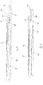
- Fig. 1 shows a first example of the set. It comprises three parts, namely the flexshaft 9, an insertion needle 10 as application tool 7and a retaining wire 13.
- the flexshaft 9 is shown schematically, only. It has a reinforced retaining hole 8 in its distal end.
- the retaining hole 8 is provided for the accommodation of the retaining wire 13 prior to and during the application of the set.
- the retaining wire 13 arrests the flexshaft 9 lying within a window 12 on one side of the insertion needle 10 next to its distal end to the insertion needle 10.
- the window 12 opens towards the inner bore 11 of the insertion needle 10 allowing the retaining wire 13 to be threaded through the retaining hole 8 of the flexshaft 9.
- the coupling device is formed by the retaining wire 13 in interaction with the retaining hole 8 and the insertion needle 10.
- the insertion needle 10 has a conical tip 14 at its distal end.
- Fig. 2 shows an example for the second embodiment of the set.
- the application tool 7 consists of an solid insertion needle 15, preferably constructed from a steel rod (without an inner bore). However it has a through bore 16 in its distal end.
- the through bore 16 is designed to accommodate a flexible multi-electrode array 17 or flexshaft.
- the flexshaft is tapering towards its distal end 18 from for example 100 micron to 40 micron (see detail Z) forming a polyimide thread.
- the set Prior to use of the application tool the set is prepared by threading the flexshaft 17 through the through bore 16 in the insertion needle 15 such that the tapered section of the flexshaft 17 is held in the area of the through bore 16.
- a predetermined breaking point is created for the polyimide thread of flexshaft 17.
- Fig. 3 shows a further embodiment of the set.
- the application tool 7 consists of a solid insertion needle 25 which can be constructed similar to insertion needle 15 of the aforementioned embodiment of the set.
- insertion needle 25 is preferably constructed from a steel rod having a through bore 26 in its distal end.
- a further component of the set in this embodiment is a separate polyimide thread 29.
- the polyimide thread 29 enables the releasable and exclusively mechanical connection of a flexible multi-electrode array 24 to the insertion needle 25.
- the flexible multi-electrode array 24 resembles the flexible multi-electrode array 9 of the first embodiment and has a retaining hole 23 in the distal end.
- the separate polyimide thread 29 is threaded through the retaining hole 23 of the flexible multi-electrode array 24 and through the through bore 26 in the insertion needle 25.
- the connection of the flexible multi-electrode array 24 to the insertion needle 25 during insertion of the flexible multi-electrode array 24 into a brain is tougher as compared to the connections in the other embodiments.
- the polyimide thread 29 is simply pulled on and cracks. Both ends of the cracked polyimide thread 29 as well as the insertion needle 25 can be pulled out from the surgery area leaving no residue behind. Accordingly, the coupling device in this case is formed by the polyimide thread 29 in interaction with the retaining hole 23 in the flexible multi-electrode array 24 and the through bore 26 in the insertion needle 25.
- the solid insertion needle has two through bores 36, 37 in its distal end.
- the separate polyimide thread 29 now needs to be threaded through both through bores 36, 37 as well as through retaining hole 23 in the flexible multi-electrode array 24. The result is a very tight and robust positioning of the array allowing it to be placed into the brain even if hard dura mater needs to be passed.
- Embodiments 3 and 4 allow to reuse the flexshaft.
- the flexshaft is costly and can be reused for instance in animal experiments.
- the flexshaft in embodiment 2 needs the thin thread at the distal end 18. Once this thread has been mechanically separated, one needs to use an entirely new flexshaft with thread since it seems impossible to fix a new thread to the already used flexshaft.
- Embodiment 4 is preferably applied when it is desirable to record electric potentials from the flexshaft electrodes during its insertion into the tissue since no separate thread runs over the flexshaft 24.
- Fig. 5 shows the embodiment of Fig. 1d . Therefore, reference is made to the respective description.
- the embodiment has been completed by a guidetube 40 providing enhanced mechanical stability to the set.
- the retaining wire 13 and the insertion needle 10 are placed inside the guidetube 40 whereas the flexshaft 9 is placed outside of the guidetube 40.
- the guidetube 40 has tip 42 having a sharp cannula-type cutting shape.
- Fig. 6 the embodiment of Fig. 4c ) is shown.
- a guidetube 41 has been added to the assembly of the other components.
- the insertion needle 35 as well as the polyimide thread 29 are placed inside the guidetube 41 whereas the flexible multi-electrode array is placed outside of the guidetube 41.
- the guidetube 41 has a tip 43 with a blunt shape.
Landscapes
- Health & Medical Sciences (AREA)
- Life Sciences & Earth Sciences (AREA)
- Surgery (AREA)
- General Health & Medical Sciences (AREA)
- Heart & Thoracic Surgery (AREA)
- Engineering & Computer Science (AREA)
- Biomedical Technology (AREA)
- Animal Behavior & Ethology (AREA)
- Public Health (AREA)
- Veterinary Medicine (AREA)
- Pathology (AREA)
- Molecular Biology (AREA)
- Medical Informatics (AREA)
- Nuclear Medicine, Radiotherapy & Molecular Imaging (AREA)
- Neurology (AREA)
- Physics & Mathematics (AREA)
- Biophysics (AREA)
- Neurosurgery (AREA)
- Psychology (AREA)
- Radiology & Medical Imaging (AREA)
- Cardiology (AREA)
- Measurement And Recording Of Electrical Phenomena And Electrical Characteristics Of The Living Body (AREA)
- Surgical Instruments (AREA)
- Electrotherapy Devices (AREA)
- Infusion, Injection, And Reservoir Apparatuses (AREA)
Description
- The use of sensor and effector arrays on flexible substrates is of growing relevance for biomedical applications. The ability to construct diverse devices on biocompatible substrates which are tolerated over long time scales will allow enhanced therapeutic and diagnostic interventions as well as improvements in brain/machine interfaces. However, it is currently difficult to implant these devices into the body in a minimally invasive way because of their otherwise desirable flexibility.
- The term thin-film strip as used hereinafter indicates a strip of thin film that is flexible and therefore cannot be inserted into living tissue by itself due to mechanical barriers like the dura mater if considering the brain as exemplified. The strip carries components that are to be deposited in the living tissue as e. g. electronic circuits, light guides, fluid vias and the like.
- Multi-electrode arrays are currently revolutionizing basic and clinical neuroscience due to their unprecedented ability to record from and stimulate in dense populations of neurons. One of the most promising technologies for fabricating multi-electrode arrays relies on the application of Micro-Electro-Mechanical Systems (MEMS) lithographic processes to realize dense arrays with arbitrary geometries on flexible, polyimide-based or parylene-based films. Such MEMS are considered as an example of flat, flexible two-dimensional thin-film strips within the scope of the present application besides others. Such techniques have been widely adopted for surface recording from the brain because they offer freedom in design, biocompatibility over long time scales, and are minimally invasive. However, many areas of the brain of especial interest for both research and clinical applications are not accessible from such surface recordings, and the targets desirable for therapeutic stimulation often lie tens of millimeters from the brain's surface. In order to achieve access to such areas, it is desirable to penetrate the brain tissue in a minimal fashion. However, current designs to achieve this goal are either macroscopic (on the order of a millimeter) or use brittle electrode substrates, such as silicon. Existing technologies thus risk unnecessary damage to the brain both during implantation, as well as in the lifetime of the implanted device.
- RUBEHN, B., et al. "Flexible shaft electrodes for transdural implantation and chronic recording". In: Proceedings of the 15th Annual Conference of the IFESS. Vienna. 2010 propose for fulfilling the contradicting requirements of stiffness of a thin-film strip to be applied during insertion and flexibility during the course of a long-term implantation a custom insertion tool for the thin-film strips, in this case for shaft electrodes. While the shaft itself is flexible, an insertion tool is used to penetrate the dura mater. The tool comprises a tungsten rod with a diameter of 100 microns and a tapered tip, and two rods with diameters of 50 microns and blunt tips. The thicker rod is glued between the two thinner ones protruding beyond them. For the implantation it is proposed that the tapered rod slides into a U-shaped profile which is glued to the back of the shaft's tip. The whole assembly is intended to be inserted into the brain, with the tapered tip of the rod penetrating the dura mater while the two blunt rods bear against the back of the U-profile, pushing it through the hole in the dura mater and into the tissue. Since it is attached to the U-profile, the flexible shaft is inserted into the brain matter. After placing the shaft at the right position, the tungsten insertion tool is withdrawn, leaving the micromachined polyimide foil (the thin-film strip) and the U-profile in the brain.
- The authors themselves observe that whilst the thin-film strip could be inserted into the cortex, it was not possible to insert it through the closed dura or pia mater. Moreover, leaving the U-profile in the brain behind can be cause for undesirable damages to the tissue.
US2011/0224682 A1 discloses an instrument for implanting an electrode which forms the basis of the preamble of claim 1. - The invention is defined by claim 1 and the dependent claims disclose the preferred embodiments. It is the object of the present invention to propose a set for applying a flat, flexible two-dimensional thin-film strip into living tissue, in particular brain, avoiding the above mentioned drawbacks as far as possible.
- The aforementioned object is achieved by a set comprising
- the thin-film strip itself to be applied,
- an application tool removable and exclusively mechanically connectable to the thin-film strip by means of a coupling device, wherein after application of the thin-film strip in the target location the application tool is removable from the tissue without residue by mechanically disengaging the coupling device itself thereby leaving the thin-film strip behind.
- The benefits of such a system include :
- the ability to target deep brain structures with flexible devices that could otherwise not penetrate at all or that could not be targeted precisely,
- implantation of the thin-film strip through minimally invasive means,
- removal of the rigid implantation device without leaving any residue so that damage to brain tissue is minimized over the lifetime of the implant,
- free determination of the timing of the insertion, i.e. the length of the penetration and the speed of release of the flexible device.
- In a particular preferred embodiment the thin-film strip is a micro-electromechanical system (MEMS) in the form of a flexible multi electrode array. The set of this embodiment of the present invention allows application of such MEMS enabling neuroscientifical measurements as mentioned above.
- It is preferred that the flexible thin-film strip is polyimide-based or parylene-based which is known per se in the field of the present invention.
- According to one preferred embodiment the flexible thin-film strip has a reinforced retaining hole in the distal end and the application tool consists of an insertion needle having an inner bore and a window on one side next to its distal end opening towards the bore and of a retaining wire designed to pass through the inner bore of the insertion needle and through said retaining hole in the thin-film strip lying in said window during insertion of the thin-film strip into the tissue, thereby removably locking up the flexible thin-film strip to the insertion needle.
- Preferably, the insertion needle is a micro-machined, surgical-grade steel tubing with an outer diameter of 200 microns and a bore of 100 microns diameter.
- In a preferred embodiment the insertion needle has a conical tip (the "insertion tip") that is sharp enough (∼18 degrees) to allow penetration of the dura mater and brain tissue.
- Preferably, the retaining wire is a surgical grade stainless steel wire of 70 microns diameter that can pass through the bore of the insertion needle.
- The insertion tool is used to insert the thin-film strip into the brain. Said thin-film strip also will be referred to as the flexshaft hereinafter. For insertion, the flexshaft is coupled to the insertion needle and then released after being positioned at the target location. For coupling of the flexshaft to the insertion needle, the flexshaft is equipped with the reinforced retaining hole close to its end. This hole can have a diameter of 80 microns and aids in retaining the flexshaft on the insertion needle. The flexshaft is laid into the window on the side of the insertion needle such that the retaining hole fits precisely over the bore of the insertion needle as exposed through the window. The retaining wire is then threaded through the retaining hole and further into the tip of the insertion needle on the other end of the window. Thereby, the flexshaft is firmly attached to the insertion needle.
- In order to form an abutment for the retaining wire the distal end of the insertion needle should be shut. Once the multi-electrode array has been placed in the area of interest, the retaining wire can then be removed, freeing the flexshaft, and subsequently, the insertion needle can be withdrawn without residue, leaving the flexshaft in place.
- According to another preferred embodiment the flexible multi-electrode array tapers into a retaining thread next to its distal end consisting of a polyimide thread and the application tool consists of a solid insertion needle having a through bore in its distal end, the polyimide thread being designed to be threaded through said through bore in the insertion needle before applying the multi-electrode array.
- In this approach, the polyimide flexshaft is coupled with the insertion needle by means of the polyimide thread. This technique allows for smaller dimensions of the insertion needle and sharper tips for penetrating tougher tissue. The insertion needle is preferably constructed from a 200 microns diameter steel rod. Preferably, the insertion needle is tapered in the initial 5.75 mm with a 3 degree angle and in the final millimeter to a 10 degree tip. It has a hole bored through the angled plane about 1 mm from the end The typical flexshaft for use with this insertion needle ends with a 5 cm long and 100 microns wide thread of polyimide which is narrowed further to 40 microns where it meets the flexshaft. This reduced polyimide retaining thread allows the flexshaft to be coupled to the insertion needle for implantation, but can be separated from the flexshaft mechanically once the device is implanted. The retaining thread is introduced through the hole in the insertion needle, coupling the flexshaft to the insertion needle. The flexshaft and retaining thread are produced from a single piece of polyimide and lie flush to the insertion needle. The flexshaft is inserted in this manner. Once the flexshaft has been inserted, the retaining thread is mechanically separated from the flexshaft by simply pulling on the retaining thread. The insertion needle can then be withdrawn without residue, while the flexshaft remains in place.
- According to still another preferred embodiment the flexible multi-electrode array has a retaining hole next to its distal end and the application tool consists of an insertion needle having a through bore in its distal end and of a separate polyimide thread being designed to be threaded through said through bore in the insertion needle as well as through the retaining hole of the flexible multi-electrode array before applying the multi-electrode array.
- In this approach, the flexshaft is coupled to the insertion needle by means of the polyimide thread. This embodiment is therefore a combination of the flexshaft of the first embodiment and the insertion needle of the second embodiment, the retaining wire of the first embodiment being replaced by the separate polyimide thread. The handling of this third embodiment is similar to the handling of the second embodiment. Before applying the flexshaft into the brain tissue the flexshaft is connected to the insertion needle by means of the separate thread by threading it through the retaining hole and through the through bore in the insertion needle. Once the flexshaft has been inserted, the polyimide thread is pulled and the mechanical connection to the flexshaft is separated such that the insertion needle and the polyimide thread can be pulled out from the surgery area without residue.
- In still another preferred embodiment the flexible multi-electrode array has a reinforced retaining hole in the distal end and the application tool consists of an insertion needle having two through bores in its distal end and of a separate polyimide thread being designed to be threaded through said through bores in the insertion needle in a loop-like manner before applying the multi-electrode array the through bores serving as loop thread guide.
- This forth embodiment is closely related to the third embodiment as described before. The handling is also very similar except for forming the loop from the polyimide thread through the through bores in the tip of the insertion needle.
- The set of the present invention and in particular all of the aforementioned embodiments can preferably be further developed by a removable guidetube which encases at least parts of the coupling device and the application tool prior to applying the assembly of application tool, coupling device and thin-film strip.
- The guidetube allows for smaller diameter insertion needles and increases the precision of localization when targeting very deep structures. This is due to the additional mechanical stability of the assembly granted by the guidetube.
- According to one embodiment, it is preferred that the tip of the guidetube has a sharp cannula-type cutting shape. This sharp-ended guidetube can penetrate through the tissue for some defined distance, prior to implantation of the application and the thin-film strip. This allows penetration of tough tissues and insures accurate targeting of very deep structures, for which the length of the application tool necessary to reach the target would result in potential bending of the application tool and subsequent misplacement.
- According to an alternative embodiment, the tip of the guidetube can have a blunt or flat shape. The blunt-ended guidetube can be positioned against the dura mater and the application tool and the thin-film strip can be implanted through the dura mater and tissue. Again, this allows deep targets to be reached while providing stability and maintaining the structural integrity of the application tool.
- Preferably, the guidetube consists of steel tube having an inner diameter of 220-260 micron and an outer diameter of 300-400 micron.
- According to a very much preferred embodiment, the guidetube is provided with a channel cut into the outside thereof for the reception of the thin-film strip allowing the thin-film strip to stay on the outside of the guidetube during its insertion into the living tissue. In use, the application tool is placed inside the guide tube whereas the thin-film strip is affixed to the application tool through the channel. Said channel allows the thin-film strip to remain in place later after the application tool and the guidetube have been removed.
- The invention will now be described in greater detail using the embodiments according to the drawing figures.
- Fig. 1
- shows a first embodiment of the set according to the invention, in particular
Fig.1a an insertion needle,
Fig 1b a retaining wire,
Fig.1c schematically a thin-film strip in the form of a flexible multi-electrode array, and
Fig 1d the set as put together, ready for use, - Fig. 2
- shows a second embodiment of the set, in particular
Fig. 2a a sectional view of an insertion needle,
Fig. 2b a top view of the insertion needle,
Fig. 2c schematically a flexible multi-electrode array, tapering to a thread in its distal section,
Fig. 2d the set as put together, - Fig. 3
- shows a third embodiment of the set, in particular
Fig. 3a an insertion needle (sectional and top view),
Fig. 3b schematically a flexible multi-electrode array,
Fig. 3c the set as put together, - Fig. 4
- shows a fourth embodiment of the set, in particular
Fig. 4a an insertion needle (sectional and top view),
Fig. 4b schematically a flexible multi-electrode array,
Fig. 4c the set as put together, - Fig. 5
- shows the embodiment of
Fig. 1d ) completed by a guidetube having a tip with a sharp cannula-type cutting shape, and - Fig. 6
- shows the embodiment of
Fig. 4c ) completed by a guidetube having a tip showing a blunt shape. -
Fig. 1 shows a first example of the set. It comprises three parts, namely the flexshaft 9, an insertion needle 10 as application tool 7and aretaining wire 13. - The flexshaft 9 is shown schematically, only. It has a reinforced retaining hole 8 in its distal end. The retaining hole 8 is provided for the accommodation of the
retaining wire 13 prior to and during the application of the set. The retainingwire 13 arrests the flexshaft 9 lying within awindow 12 on one side of the insertion needle 10 next to its distal end to the insertion needle 10. For this purpose thewindow 12 opens towards the inner bore 11 of the insertion needle 10 allowing the retainingwire 13 to be threaded through the retaining hole 8 of the flexshaft 9. In this case the coupling device is formed by the retainingwire 13 in interaction with the retaining hole 8 and the insertion needle 10. - To ease the penetration of the dura mater the insertion needle 10 has a
conical tip 14 at its distal end. -
Fig. 2 shows an example for the second embodiment of the set. As shown the application tool 7 consists of ansolid insertion needle 15, preferably constructed from a steel rod (without an inner bore). However it has a throughbore 16 in its distal end. The throughbore 16 is designed to accommodate a flexible multi-electrode array 17 or flexshaft. The flexshaft is tapering towards itsdistal end 18 from for example 100 micron to 40 micron (see detail Z) forming a polyimide thread. - Prior to use of the application tool the set is prepared by threading the flexshaft 17 through the through
bore 16 in theinsertion needle 15 such that the tapered section of the flexshaft 17 is held in the area of the throughbore 16. In this combination a predetermined breaking point is created for the polyimide thread of flexshaft 17. Once the flexshaft 17 has been positioned in the area of interest the retaining thread of flexshaft 17 is separated from the flexshaft by simply pulling on itsdistal end 18, the retaining thread, which will lead to its breaking in the throughbore 16. Then theinsertion needle 15 can be pulled out from the surgery area without residue. Accordingly, the coupling device is formed by thedistal end 18 of the flexible multi-electrode array 17 in interaction with the throughbore 16 in theinsertion needle 15. -
Fig. 3 shows a further embodiment of the set. Here, the application tool 7 consists of asolid insertion needle 25 which can be constructed similar toinsertion needle 15 of the aforementioned embodiment of the set. This does mean thatinsertion needle 25 is preferably constructed from a steel rod having a throughbore 26 in its distal end. A further component of the set in this embodiment is aseparate polyimide thread 29. Thepolyimide thread 29 enables the releasable and exclusively mechanical connection of a flexiblemulti-electrode array 24 to theinsertion needle 25. For this reason the flexiblemulti-electrode array 24 resembles the flexible multi-electrode array 9 of the first embodiment and has a retaininghole 23 in the distal end. Now, for preparation of the application tool theseparate polyimide thread 29 is threaded through the retaininghole 23 of the flexiblemulti-electrode array 24 and through the throughbore 26 in theinsertion needle 25. The connection of the flexiblemulti-electrode array 24 to theinsertion needle 25 during insertion of the flexiblemulti-electrode array 24 into a brain is tougher as compared to the connections in the other embodiments. - Once the flexible
multi-electrode array 24 has reached the desired position in the tissue thepolyimide thread 29 is simply pulled on and cracks. Both ends of the crackedpolyimide thread 29 as well as theinsertion needle 25 can be pulled out from the surgery area leaving no residue behind. Accordingly, the coupling device in this case is formed by thepolyimide thread 29 in interaction with the retaininghole 23 in the flexiblemulti-electrode array 24 and the throughbore 26 in theinsertion needle 25. - An even tougher connection between a flexible multi-electrode array and an insertion needle can be achieved by means of the embodiment according to
Fig. 4 . - This embodiment is very similar to the aforementioned embodiment. This is the reason why merely the differences will be highlighted hereinafter. Apart from that reference is made to the details of embodiment 3.
- Here, the solid insertion needle has two through
bores separate polyimide thread 29 now needs to be threaded through both throughbores hole 23 in the flexiblemulti-electrode array 24. The result is a very tight and robust positioning of the array allowing it to be placed into the brain even if hard dura mater needs to be passed. - Embodiments 3 and 4 allow to reuse the flexshaft. The flexshaft is costly and can be reused for instance in animal experiments. In contrast thereto the flexshaft in embodiment 2 needs the thin thread at the
distal end 18. Once this thread has been mechanically separated, one needs to use an entirely new flexshaft with thread since it seems impossible to fix a new thread to the already used flexshaft. - Embodiment 4 is preferably applied when it is desirable to record electric potentials from the flexshaft electrodes during its insertion into the tissue since no separate thread runs over the
flexshaft 24. -
Fig. 5 shows the embodiment ofFig. 1d . Therefore, reference is made to the respective description. However, here the embodiment has been completed by aguidetube 40 providing enhanced mechanical stability to the set. As can be seen, the retainingwire 13 and the insertion needle 10 are placed inside theguidetube 40 whereas the flexshaft 9 is placed outside of theguidetube 40. In this embodiment theguidetube 40 hastip 42 having a sharp cannula-type cutting shape. - In
Fig. 6 the embodiment ofFig. 4c ) is shown. For the minutes reference is made to the description thereof. However, here aguidetube 41 has been added to the assembly of the other components. Clearly, theinsertion needle 35 as well as thepolyimide thread 29 are placed inside theguidetube 41 whereas the flexible multi-electrode array is placed outside of theguidetube 41. Here theguidetube 41 has atip 43 with a blunt shape. -
- 6
- flexible thin-film strip
- 7
- application tool
- 8
- retaining hole
- 9
- flexible multi-electrode array
- 10
- insertion needle
- 11
- inner bore
- 12
- window
- 13
- retaining wire
- 14
- conical tip
- 15
- insertion needle
- 16
- through bore
- 17
- flexible multi-electrode array
- 18
- distal end
- 23
- retaining hole
- 24
- flexible multi-electrode array
- 25
- insertion needle
- 26
- through bore
- 29
- polyimide thread
- 35
- insertion needle
- 36
- through bore
- 37
- through bore
- 40
- guidetube
- 41
- guidetube
- 42
- tip
- 43
- tip
Claims (17)
- Set for applying a flat, flexible two-dimensional thin-film strip into living tissue, in particular brain comprising- the thin-film strip (6) itself to be applied,- an application tool (7) removable and exclusively mechanically connectable to the thin-film strip (6) by means of a coupling device (8,13;15,16,18;23,29;29,36,37), wherein:so that after application of the thin-film strip (6) in the target location the application tool (7) is removable from the tissue without residue by mechanically disengaging the coupling device (8,13;15,16,18;23,29;29,36,37) itself thereby leaving the thin-film strip (6) behind.a thread (29), wire (13) or needle (15, 25, 35) is configured to couple the thin-film strip (6) to the application tool (7) by means of a retaining hole (8, 23) in the thin-film, such that withdrawal or removal of the thread (29), wire (13) or needle (15, 25, 35) releases the thin-film strip from the application tool; orthe thin-film strip (6) tapers into a retaining thread configured to thread through a through bore (16) in the application tool (7), such that the thin-film strip (6) is releasable from the application tool (7) by pulling the thread and thereby separating the thread from the rest of the thin-film strip (6);
- The set of claim 1, wherein the thin-film strip (6) is a micro-electromechanical system (MEMS) in the form of a flexible multi electrode array.
- The set of claim 1 or 2, wherein the flexible thin-film strip (6) is polyimide-based or parylene-based.
- The set of claim 1, 2 or 3, wherein the flexible thin-film strip (6) has a reinforced retaining hole (8) in the distal end and wherein the application tool (7) consists of an insertion needle (10) having an inner bore (11) and a window (12) on one side next to its distal end opening towards the inner bore (11) and of a retaining wire (13) designed to pass through the inner bore (11) of the insertion needle (10) and through said retaining hole (8) in the thin-film strip (6) lying in said window (12) during insertion of the thin-film strip (6) into the tissue, thereby removably locking up the thin-film strip (6) to the insertion needle (10).
- The set of claim 4, wherein the insertion needle (10) is a micro-machined surgical-grade steel tubing with an outer diameter of 200 micron with an inner bore (11) of 100 micron diameter.
- The set of claim 4 or 5, wherein the insertion needle (10) has a conical tip (14) which is sharp enough to allow penetration of the dura mater and brain tissue.
- The set of claims 4, 5 or 6, wherein the retaining wire is a surgical-grade stainless steel wire having a diameter of 70 micron.
- The set of claim 1, 2 or 3, wherein the flexible thin-film strip (6) tapers into a retaining thread next to its distal end (18) consisting of a polyimide thread and wherein the application tool consists of a solid insertion needle (15) having a through bore (16) in its distal end the polyimide thread being designed to be threaded through said through bore (16) in the insertion needle (15) before applying the thin-film strip (6).
- The set of claim 1, 2 or 3, wherein the flexible thin-film strip (6) has a reinforced retaining hole (23) in the distal end and wherein the application tool consists of a solid insertion needle (25) having a through bore (26) in its distal end and of a separate polyimide thread (29) being designed to be threaded through said through bore (26) in the insertion needle (25) and through the retaining hole (23) in the flexible thin-film strip (6) before applying the thin-film strip.
- The set of claim 1, 2 or 3, wherein the flexible thin-film strip (6) has a reinforced retaining hole (23) in the distal end and wherein the application tool consists of a solid insertion needle (35) having two through bores (36,37) in its distal end and of a separate polyimide thread (29) being designed to be threaded through said through bores (36,37) in the insertion needle (25) in a loop-like manner as well as through the retaining hole (23) of the flexible thin-film strip (6) before applying the thin-film strip, the through bores serving as loop thread guide.
- The set of claim 8, 9 or 10, wherein the insertion needle is constructed from a 200 micron diameter steel rod.
- The set of claim 8, 9, 10 or 11, wherein the insertion needle is tapered in the initial 5,75 mm with a 3° angle and in the final distal millimeter to a 10°tip.
- The set of any preceding claims, wherein at least parts of the coupling device (13;18;29) and the application tool (7) are encased in a removable guidetube (40;41) prior to applying the assembly of application tool (7), coupling device (13;18;29) and the thin-film strip (6).
- The set of claim 13, wherein the tip (42) of the guidetube (40) has a sharp cutting shape.
- The set of claim 13, wherein the tip (43) of the guidetube (41) has a blunt shape.
- The set of any of the claims 13, 14 or 15, wherein the guidetube (40;41) consists of steel tube having an inner diameter of 220-260 micron and an outer diameter of 300-400 micron.
- The set of any of the claims 13 through 16, wherein the guidetube (40;41) has a channel cut into the outside for the reception of the thin-film strip (6) allowing the thin-film strip (6) to remain on the outside of the guidetube (40;41) during its insertion into the living tissue.
Applications Claiming Priority (2)
| Application Number | Priority Date | Filing Date | Title |
|---|---|---|---|
| EP14169867 | 2014-05-26 | ||
| PCT/EP2015/052944 WO2015180847A1 (en) | 2014-05-26 | 2015-02-12 | Set for applying a flat, flexible two-dimensional thin-film strip into living tissue |
Publications (2)
| Publication Number | Publication Date |
|---|---|
| EP3148454A1 EP3148454A1 (en) | 2017-04-05 |
| EP3148454B1 true EP3148454B1 (en) | 2019-11-27 |
Family
ID=50943053
Family Applications (1)
| Application Number | Title | Priority Date | Filing Date |
|---|---|---|---|
| EP15703789.6A Active EP3148454B1 (en) | 2014-05-26 | 2015-02-12 | Set for applying a flat, flexible two-dimensional thin-film strip into living tissue |
Country Status (7)
| Country | Link |
|---|---|
| US (1) | US11141112B2 (en) |
| EP (1) | EP3148454B1 (en) |
| JP (1) | JP2017523887A (en) |
| CN (1) | CN106535793B (en) |
| AU (1) | AU2015266325A1 (en) |
| CA (1) | CA2948406C (en) |
| WO (1) | WO2015180847A1 (en) |
Families Citing this family (13)
| Publication number | Priority date | Publication date | Assignee | Title |
|---|---|---|---|---|
| EP3237058B1 (en) * | 2014-12-23 | 2022-02-16 | The Regents of The University of California | Compositions, and systems for device implantation |
| US10709444B2 (en) * | 2017-01-24 | 2020-07-14 | Allergan Industrie Sas | Thread insertion devices |
| CN108903916B (en) * | 2018-07-31 | 2024-04-02 | 浙江大学 | Implantation needle and implantation method of flexible implantation type biosensor and photoelectric device |
| US12005205B2 (en) * | 2019-12-16 | 2024-06-11 | Stryker Corporation | Guidewires for medical devices |
| WO2021152100A1 (en) | 2020-01-30 | 2021-08-05 | INSERM (Institut National de la Santé et de la Recherche Médicale) | Insertion device and assembly comprising such insertion device and a flexible implantable strip |
| CN112386262A (en) * | 2020-11-18 | 2021-02-23 | 中国科学院半导体研究所 | U-shaped flexible electrode implantation system and preparation method thereof |
| CN114788700A (en) * | 2022-02-25 | 2022-07-26 | 武汉衷华脑机融合科技发展有限公司 | Neural interface with auxiliary structure |
| CN115054334B (en) * | 2022-06-20 | 2024-10-01 | 上海阶梯医疗科技有限公司 | Method for guiding flexible electrode and system for implanting flexible electrode |
| CN115429282B (en) * | 2022-07-25 | 2024-02-06 | 武汉衷华脑机融合科技发展有限公司 | Composite microneedle structure and nerve microelectrode |
| CN116439718B (en) * | 2023-06-16 | 2023-09-26 | 北京智冉医疗科技有限公司 | Ancillary implant components, kits and systems for flexible neural electrodes |
| CN118452935B (en) * | 2024-07-11 | 2024-09-27 | 北京智冉医疗科技有限公司 | Implantable flexible electrode, device and kit |
| WO2026072812A1 (en) * | 2024-09-25 | 2026-04-02 | Neuroone Medical Technologies Corporation | Spinal cord stimulation device implantation methods and related systems and devices |
| KR102962878B1 (en) * | 2024-10-25 | 2026-05-08 | 사회복지법인 삼성생명공익재단 | A penetrating type flexible nerve electrode |
Family Cites Families (14)
| Publication number | Priority date | Publication date | Assignee | Title |
|---|---|---|---|---|
| DE3447642C1 (en) * | 1984-12-28 | 1986-09-18 | Bernhard M. Dr. 5600 Wuppertal Cramer | Steerable guidewire for catheters |
| US20100331883A1 (en) * | 2004-10-15 | 2010-12-30 | Schmitz Gregory P | Access and tissue modification systems and methods |
| US7655014B2 (en) | 2004-12-06 | 2010-02-02 | Cameron Health, Inc. | Apparatus and method for subcutaneous electrode insertion |
| WO2006138300A2 (en) * | 2005-06-15 | 2006-12-28 | Poly-Med, Inc. | Bioswellable sutures |
| US8718793B2 (en) * | 2006-08-01 | 2014-05-06 | Cameron Health, Inc. | Electrode insertion tools, lead assemblies, kits and methods for placement of cardiac device electrodes |
| US8348973B2 (en) * | 2006-09-06 | 2013-01-08 | Covidien Lp | Bioactive substance in a barbed suture |
| US10925637B2 (en) | 2010-03-11 | 2021-02-23 | Mainstay Medical Limited | Methods of implanting electrode leads for use with implantable neuromuscular electrical stimulator |
| US8742064B2 (en) * | 2007-10-23 | 2014-06-03 | Solvay Advanced Polymers, L.L.C. | Medical tubings made of a polymer material |
| US20090125097A1 (en) * | 2007-11-13 | 2009-05-14 | Medtronic Vascular, Inc. | Device and Method for Stent Graft Fenestration in Situ |
| GB0806555D0 (en) * | 2008-04-10 | 2008-05-14 | Univ Keele | Neural circuits |
| EP2604313B1 (en) * | 2008-11-12 | 2014-09-17 | Ecole Polytechnique Federale de Lausanne | Microfabricated neurostimulation device |
| AU2011248487A1 (en) * | 2010-05-02 | 2012-11-08 | Nervive, Inc. | Modulating function of the facial nerve system or related neural structures via the ear |
| BR112012030160B1 (en) * | 2010-05-27 | 2020-11-03 | Iscience Interventional Corporation | tool and device for total circumferential insertion for an implant in the schlemm canal of the eye |
| US20130018444A1 (en) * | 2011-07-11 | 2013-01-17 | Glenn Richard A | Intravascular electrodes for transvascular stimulation |
-
2015
- 2015-02-12 US US15/313,211 patent/US11141112B2/en active Active
- 2015-02-12 CN CN201580027686.6A patent/CN106535793B/en not_active Expired - Fee Related
- 2015-02-12 AU AU2015266325A patent/AU2015266325A1/en not_active Abandoned
- 2015-02-12 JP JP2017514789A patent/JP2017523887A/en active Pending
- 2015-02-12 WO PCT/EP2015/052944 patent/WO2015180847A1/en not_active Ceased
- 2015-02-12 CA CA2948406A patent/CA2948406C/en active Active
- 2015-02-12 EP EP15703789.6A patent/EP3148454B1/en active Active
Non-Patent Citations (1)
| Title |
|---|
| None * |
Also Published As
| Publication number | Publication date |
|---|---|
| JP2017523887A (en) | 2017-08-24 |
| CN106535793B (en) | 2020-07-14 |
| EP3148454A1 (en) | 2017-04-05 |
| CA2948406C (en) | 2021-09-14 |
| US11141112B2 (en) | 2021-10-12 |
| WO2015180847A1 (en) | 2015-12-03 |
| US20170181707A1 (en) | 2017-06-29 |
| AU2015266325A1 (en) | 2016-11-24 |
| CN106535793A (en) | 2017-03-22 |
| CA2948406A1 (en) | 2015-12-03 |
Similar Documents
| Publication | Publication Date | Title |
|---|---|---|
| US11141112B2 (en) | Set for applying a flat, flexible two-dimensional thin-film strip into living tissue | |
| Thielen et al. | A comparison of insertion methods for surgical placement of penetrating neural interfaces | |
| Zhao et al. | Parallel, minimally-invasive implantation of ultra-flexible neural electrode arrays | |
| CA2874792C (en) | Cranial drill system | |
| JP5587190B2 (en) | Stereotaxic device | |
| Hussong et al. | Conception and design of an automated insertion tool for cochlear implants | |
| Kim et al. | A hybrid silicon–parylene neural probe with locally flexible regions | |
| CN102858400B (en) | Systems and methods for removal of intravascular leads | |
| EP2358428B1 (en) | Implant electrode and accessories for use in robotic surgery | |
| US20090187196A1 (en) | Guide tube for an implantable device system | |
| JP2014054541A (en) | Multi-probe skull fixing device low in height and method for using the same | |
| Weber et al. | Minimally invasive, robot assisted cochlear implantation | |
| Zhao et al. | Flexible deep brain neural probes based on a parylene tube structure | |
| EP3160406A2 (en) | Apparatus for perforation and aspiration of inner ear | |
| WO2013016556A2 (en) | Anchor wire system and method | |
| US20230041785A1 (en) | Biopsy device and method for tissue sampling in mammals | |
| US20240307677A1 (en) | Subdural Sound System With a Receiving Lumen for Placing Electrodes | |
| Johnson et al. | Micro-molded cannulae for intracochlear infusions in small rodents | |
| WO2018076046A1 (en) | Access device for providing access to a fixation element fixed to tissue | |
| CN119587035A (en) | A brain-computer interface system and method of using the same |
Legal Events
| Date | Code | Title | Description |
|---|---|---|---|
| STAA | Information on the status of an ep patent application or granted ep patent |
Free format text: STATUS: THE INTERNATIONAL PUBLICATION HAS BEEN MADE |
|
| PUAI | Public reference made under article 153(3) epc to a published international application that has entered the european phase |
Free format text: ORIGINAL CODE: 0009012 |
|
| STAA | Information on the status of an ep patent application or granted ep patent |
Free format text: STATUS: REQUEST FOR EXAMINATION WAS MADE |
|
| 17P | Request for examination filed |
Effective date: 20161122 |
|
| AK | Designated contracting states |
Kind code of ref document: A1 Designated state(s): AL AT BE BG CH CY CZ DE DK EE ES FI FR GB GR HR HU IE IS IT LI LT LU LV MC MK MT NL NO PL PT RO RS SE SI SK SM TR |
|
| AX | Request for extension of the european patent |
Extension state: BA ME |
|
| DAX | Request for extension of the european patent (deleted) | ||
| STAA | Information on the status of an ep patent application or granted ep patent |
Free format text: STATUS: EXAMINATION IS IN PROGRESS |
|
| 17Q | First examination report despatched |
Effective date: 20180910 |
|
| GRAP | Despatch of communication of intention to grant a patent |
Free format text: ORIGINAL CODE: EPIDOSNIGR1 |
|
| STAA | Information on the status of an ep patent application or granted ep patent |
Free format text: STATUS: GRANT OF PATENT IS INTENDED |
|
| INTG | Intention to grant announced |
Effective date: 20190702 |
|
| RIN1 | Information on inventor provided before grant (corrected) |
Inventor name: FRIES, PASCAL Inventor name: LEWIS, CHRISTOPHER |
|
| GRAS | Grant fee paid |
Free format text: ORIGINAL CODE: EPIDOSNIGR3 |
|
| GRAA | (expected) grant |
Free format text: ORIGINAL CODE: 0009210 |
|
| STAA | Information on the status of an ep patent application or granted ep patent |
Free format text: STATUS: THE PATENT HAS BEEN GRANTED |
|
| AK | Designated contracting states |
Kind code of ref document: B1 Designated state(s): AL AT BE BG CH CY CZ DE DK EE ES FI FR GB GR HR HU IE IS IT LI LT LU LV MC MK MT NL NO PL PT RO RS SE SI SK SM TR |
|
| REG | Reference to a national code |
Ref country code: GB Ref legal event code: FG4D |
|
| REG | Reference to a national code |
Ref country code: CH Ref legal event code: EP |
|
| REG | Reference to a national code |
Ref country code: AT Ref legal event code: REF Ref document number: 1205850 Country of ref document: AT Kind code of ref document: T Effective date: 20191215 |
|
| REG | Reference to a national code |
Ref country code: DE Ref legal event code: R096 Ref document number: 602015042446 Country of ref document: DE |
|
| REG | Reference to a national code |
Ref country code: IE Ref legal event code: FG4D |
|
| REG | Reference to a national code |
Ref country code: CH Ref legal event code: NV Representative=s name: E. BLUM AND CO. AG PATENT- UND MARKENANWAELTE , CH |
|
| REG | Reference to a national code |
Ref country code: NL Ref legal event code: MP Effective date: 20191127 |
|
| REG | Reference to a national code |
Ref country code: LT Ref legal event code: MG4D |
|
| PG25 | Lapsed in a contracting state [announced via postgrant information from national office to epo] |
Ref country code: GR Free format text: LAPSE BECAUSE OF FAILURE TO SUBMIT A TRANSLATION OF THE DESCRIPTION OR TO PAY THE FEE WITHIN THE PRESCRIBED TIME-LIMIT Effective date: 20200228 Ref country code: NO Free format text: LAPSE BECAUSE OF FAILURE TO SUBMIT A TRANSLATION OF THE DESCRIPTION OR TO PAY THE FEE WITHIN THE PRESCRIBED TIME-LIMIT Effective date: 20200227 Ref country code: BG Free format text: LAPSE BECAUSE OF FAILURE TO SUBMIT A TRANSLATION OF THE DESCRIPTION OR TO PAY THE FEE WITHIN THE PRESCRIBED TIME-LIMIT Effective date: 20200227 Ref country code: LT Free format text: LAPSE BECAUSE OF FAILURE TO SUBMIT A TRANSLATION OF THE DESCRIPTION OR TO PAY THE FEE WITHIN THE PRESCRIBED TIME-LIMIT Effective date: 20191127 Ref country code: FI Free format text: LAPSE BECAUSE OF FAILURE TO SUBMIT A TRANSLATION OF THE DESCRIPTION OR TO PAY THE FEE WITHIN THE PRESCRIBED TIME-LIMIT Effective date: 20191127 Ref country code: SE Free format text: LAPSE BECAUSE OF FAILURE TO SUBMIT A TRANSLATION OF THE DESCRIPTION OR TO PAY THE FEE WITHIN THE PRESCRIBED TIME-LIMIT Effective date: 20191127 Ref country code: LV Free format text: LAPSE BECAUSE OF FAILURE TO SUBMIT A TRANSLATION OF THE DESCRIPTION OR TO PAY THE FEE WITHIN THE PRESCRIBED TIME-LIMIT Effective date: 20191127 Ref country code: NL Free format text: LAPSE BECAUSE OF FAILURE TO SUBMIT A TRANSLATION OF THE DESCRIPTION OR TO PAY THE FEE WITHIN THE PRESCRIBED TIME-LIMIT Effective date: 20191127 |
|
| PG25 | Lapsed in a contracting state [announced via postgrant information from national office to epo] |
Ref country code: IS Free format text: LAPSE BECAUSE OF FAILURE TO SUBMIT A TRANSLATION OF THE DESCRIPTION OR TO PAY THE FEE WITHIN THE PRESCRIBED TIME-LIMIT Effective date: 20200327 Ref country code: HR Free format text: LAPSE BECAUSE OF FAILURE TO SUBMIT A TRANSLATION OF THE DESCRIPTION OR TO PAY THE FEE WITHIN THE PRESCRIBED TIME-LIMIT Effective date: 20191127 Ref country code: RS Free format text: LAPSE BECAUSE OF FAILURE TO SUBMIT A TRANSLATION OF THE DESCRIPTION OR TO PAY THE FEE WITHIN THE PRESCRIBED TIME-LIMIT Effective date: 20191127 |
|
| PG25 | Lapsed in a contracting state [announced via postgrant information from national office to epo] |
Ref country code: AL Free format text: LAPSE BECAUSE OF FAILURE TO SUBMIT A TRANSLATION OF THE DESCRIPTION OR TO PAY THE FEE WITHIN THE PRESCRIBED TIME-LIMIT Effective date: 20191127 |
|
| PG25 | Lapsed in a contracting state [announced via postgrant information from national office to epo] |
Ref country code: ES Free format text: LAPSE BECAUSE OF FAILURE TO SUBMIT A TRANSLATION OF THE DESCRIPTION OR TO PAY THE FEE WITHIN THE PRESCRIBED TIME-LIMIT Effective date: 20191127 Ref country code: DK Free format text: LAPSE BECAUSE OF FAILURE TO SUBMIT A TRANSLATION OF THE DESCRIPTION OR TO PAY THE FEE WITHIN THE PRESCRIBED TIME-LIMIT Effective date: 20191127 Ref country code: EE Free format text: LAPSE BECAUSE OF FAILURE TO SUBMIT A TRANSLATION OF THE DESCRIPTION OR TO PAY THE FEE WITHIN THE PRESCRIBED TIME-LIMIT Effective date: 20191127 Ref country code: PT Free format text: LAPSE BECAUSE OF FAILURE TO SUBMIT A TRANSLATION OF THE DESCRIPTION OR TO PAY THE FEE WITHIN THE PRESCRIBED TIME-LIMIT Effective date: 20200419 Ref country code: RO Free format text: LAPSE BECAUSE OF FAILURE TO SUBMIT A TRANSLATION OF THE DESCRIPTION OR TO PAY THE FEE WITHIN THE PRESCRIBED TIME-LIMIT Effective date: 20191127 Ref country code: CZ Free format text: LAPSE BECAUSE OF FAILURE TO SUBMIT A TRANSLATION OF THE DESCRIPTION OR TO PAY THE FEE WITHIN THE PRESCRIBED TIME-LIMIT Effective date: 20191127 |
|
| REG | Reference to a national code |
Ref country code: DE Ref legal event code: R097 Ref document number: 602015042446 Country of ref document: DE |
|
| PG25 | Lapsed in a contracting state [announced via postgrant information from national office to epo] |
Ref country code: SM Free format text: LAPSE BECAUSE OF FAILURE TO SUBMIT A TRANSLATION OF THE DESCRIPTION OR TO PAY THE FEE WITHIN THE PRESCRIBED TIME-LIMIT Effective date: 20191127 Ref country code: SK Free format text: LAPSE BECAUSE OF FAILURE TO SUBMIT A TRANSLATION OF THE DESCRIPTION OR TO PAY THE FEE WITHIN THE PRESCRIBED TIME-LIMIT Effective date: 20191127 |
|
| REG | Reference to a national code |
Ref country code: AT Ref legal event code: MK05 Ref document number: 1205850 Country of ref document: AT Kind code of ref document: T Effective date: 20191127 |
|
| PLBE | No opposition filed within time limit |
Free format text: ORIGINAL CODE: 0009261 |
|
| STAA | Information on the status of an ep patent application or granted ep patent |
Free format text: STATUS: NO OPPOSITION FILED WITHIN TIME LIMIT |
|
| REG | Reference to a national code |
Ref country code: BE Ref legal event code: MM Effective date: 20200229 |
|
| PG25 | Lapsed in a contracting state [announced via postgrant information from national office to epo] |
Ref country code: MC Free format text: LAPSE BECAUSE OF FAILURE TO SUBMIT A TRANSLATION OF THE DESCRIPTION OR TO PAY THE FEE WITHIN THE PRESCRIBED TIME-LIMIT Effective date: 20191127 Ref country code: LU Free format text: LAPSE BECAUSE OF NON-PAYMENT OF DUE FEES Effective date: 20200212 |
|
| 26N | No opposition filed |
Effective date: 20200828 |
|
| PG25 | Lapsed in a contracting state [announced via postgrant information from national office to epo] |
Ref country code: PL Free format text: LAPSE BECAUSE OF FAILURE TO SUBMIT A TRANSLATION OF THE DESCRIPTION OR TO PAY THE FEE WITHIN THE PRESCRIBED TIME-LIMIT Effective date: 20191127 Ref country code: AT Free format text: LAPSE BECAUSE OF FAILURE TO SUBMIT A TRANSLATION OF THE DESCRIPTION OR TO PAY THE FEE WITHIN THE PRESCRIBED TIME-LIMIT Effective date: 20191127 Ref country code: SI Free format text: LAPSE BECAUSE OF FAILURE TO SUBMIT A TRANSLATION OF THE DESCRIPTION OR TO PAY THE FEE WITHIN THE PRESCRIBED TIME-LIMIT Effective date: 20191127 |
|
| PG25 | Lapsed in a contracting state [announced via postgrant information from national office to epo] |
Ref country code: IT Free format text: LAPSE BECAUSE OF FAILURE TO SUBMIT A TRANSLATION OF THE DESCRIPTION OR TO PAY THE FEE WITHIN THE PRESCRIBED TIME-LIMIT Effective date: 20191127 Ref country code: IE Free format text: LAPSE BECAUSE OF NON-PAYMENT OF DUE FEES Effective date: 20200212 |
|
| PG25 | Lapsed in a contracting state [announced via postgrant information from national office to epo] |
Ref country code: BE Free format text: LAPSE BECAUSE OF NON-PAYMENT OF DUE FEES Effective date: 20200229 |
|
| PG25 | Lapsed in a contracting state [announced via postgrant information from national office to epo] |
Ref country code: TR Free format text: LAPSE BECAUSE OF FAILURE TO SUBMIT A TRANSLATION OF THE DESCRIPTION OR TO PAY THE FEE WITHIN THE PRESCRIBED TIME-LIMIT Effective date: 20191127 Ref country code: MT Free format text: LAPSE BECAUSE OF FAILURE TO SUBMIT A TRANSLATION OF THE DESCRIPTION OR TO PAY THE FEE WITHIN THE PRESCRIBED TIME-LIMIT Effective date: 20191127 Ref country code: CY Free format text: LAPSE BECAUSE OF FAILURE TO SUBMIT A TRANSLATION OF THE DESCRIPTION OR TO PAY THE FEE WITHIN THE PRESCRIBED TIME-LIMIT Effective date: 20191127 |
|
| PG25 | Lapsed in a contracting state [announced via postgrant information from national office to epo] |
Ref country code: MK Free format text: LAPSE BECAUSE OF FAILURE TO SUBMIT A TRANSLATION OF THE DESCRIPTION OR TO PAY THE FEE WITHIN THE PRESCRIBED TIME-LIMIT Effective date: 20191127 |
|
| PGFP | Annual fee paid to national office [announced via postgrant information from national office to epo] |
Ref country code: CH Payment date: 20230307 Year of fee payment: 9 |
|
| P01 | Opt-out of the competence of the unified patent court (upc) registered |
Effective date: 20230517 |
|
| REG | Reference to a national code |
Ref country code: CH Ref legal event code: PL |
|
| PG25 | Lapsed in a contracting state [announced via postgrant information from national office to epo] |
Ref country code: CH Free format text: LAPSE BECAUSE OF NON-PAYMENT OF DUE FEES Effective date: 20240229 |
|
| PG25 | Lapsed in a contracting state [announced via postgrant information from national office to epo] |
Ref country code: CH Free format text: LAPSE BECAUSE OF NON-PAYMENT OF DUE FEES Effective date: 20240229 |
|
| PGFP | Annual fee paid to national office [announced via postgrant information from national office to epo] |
Ref country code: GB Payment date: 20260219 Year of fee payment: 12 |
|
| PGFP | Annual fee paid to national office [announced via postgrant information from national office to epo] |
Ref country code: DE Payment date: 20260217 Year of fee payment: 12 |
|
| PGFP | Annual fee paid to national office [announced via postgrant information from national office to epo] |
Ref country code: FR Payment date: 20260223 Year of fee payment: 12 |