EP3148421B1 - Method of determining stiffness index of arterial network and system thereof - Google Patents
Method of determining stiffness index of arterial network and system thereof Download PDFInfo
- Publication number
- EP3148421B1 EP3148421B1 EP15799720.6A EP15799720A EP3148421B1 EP 3148421 B1 EP3148421 B1 EP 3148421B1 EP 15799720 A EP15799720 A EP 15799720A EP 3148421 B1 EP3148421 B1 EP 3148421B1
- Authority
- EP
- European Patent Office
- Prior art keywords
- impulse response
- arterial network
- microprocessor
- pulse
- human subject
- Prior art date
- Legal status (The legal status is an assumption and is not a legal conclusion. Google has not performed a legal analysis and makes no representation as to the accuracy of the status listed.)
- Not-in-force
Links
Images



Classifications
-
- A—HUMAN NECESSITIES
- A61—MEDICAL OR VETERINARY SCIENCE; HYGIENE
- A61B—DIAGNOSIS; SURGERY; IDENTIFICATION
- A61B5/00—Measuring for diagnostic purposes; Identification of persons
- A61B5/02—Detecting, measuring or recording for evaluating the cardiovascular system, e.g. pulse, heart rate, blood pressure or blood flow
- A61B5/024—Measuring pulse rate or heart rate
- A61B5/0255—Recording instruments specially adapted therefor
-
- A—HUMAN NECESSITIES
- A61—MEDICAL OR VETERINARY SCIENCE; HYGIENE
- A61B—DIAGNOSIS; SURGERY; IDENTIFICATION
- A61B5/00—Measuring for diagnostic purposes; Identification of persons
- A61B5/02—Detecting, measuring or recording for evaluating the cardiovascular system, e.g. pulse, heart rate, blood pressure or blood flow
- A61B5/02007—Evaluating blood vessel condition, e.g. elasticity, compliance
-
- A—HUMAN NECESSITIES
- A61—MEDICAL OR VETERINARY SCIENCE; HYGIENE
- A61B—DIAGNOSIS; SURGERY; IDENTIFICATION
- A61B5/00—Measuring for diagnostic purposes; Identification of persons
- A61B5/02—Detecting, measuring or recording for evaluating the cardiovascular system, e.g. pulse, heart rate, blood pressure or blood flow
- A61B5/021—Measuring pressure in heart or blood vessels
- A61B5/02108—Measuring pressure in heart or blood vessels from analysis of pulse wave characteristics
- A61B5/02116—Measuring pressure in heart or blood vessels from analysis of pulse wave characteristics of pulse wave amplitude
-
- A—HUMAN NECESSITIES
- A61—MEDICAL OR VETERINARY SCIENCE; HYGIENE
- A61B—DIAGNOSIS; SURGERY; IDENTIFICATION
- A61B5/00—Measuring for diagnostic purposes; Identification of persons
- A61B5/72—Signal processing specially adapted for physiological signals or for diagnostic purposes
- A61B5/7235—Details of waveform analysis
- A61B5/7246—Details of waveform analysis using correlation, e.g. template matching or determination of similarity
-
- A—HUMAN NECESSITIES
- A61—MEDICAL OR VETERINARY SCIENCE; HYGIENE
- A61B—DIAGNOSIS; SURGERY; IDENTIFICATION
- A61B5/00—Measuring for diagnostic purposes; Identification of persons
- A61B5/72—Signal processing specially adapted for physiological signals or for diagnostic purposes
- A61B5/7271—Specific aspects of physiological measurement analysis
- A61B5/7282—Event detection, e.g. detecting unique waveforms indicative of a medical condition
Definitions
- the present invention relates to a method of determining the stiffness index of an arterial network and in particular to a method of determining the arterial stiffness index from a radial pulse waveform.
- pulse waves also known as aortic pulses
- aortic pulses are generated and propagated along the arterial network of the cardiovascular system.
- wave reflections will be produced.
- These wave reflections could be captured at various measurement sites.
- the wave reflections measured at the wrist of a human body is known as radial pulse waveform.
- Previous researches have proposed using the ratio of late systolic peak to early systolic peak of the radial pulse waveform as the arterial stiffness index. Nonetheless, an accurate location of early systolic peak and late systolic peak is not a trivial task.
- the early systolic peak and late systolic peak may be too close to each other.
- the amplitude of the late systolic component is too small compared to that of the early systolic component.
- the present invention is a method of determining a stiffness index of an arterial network of a human subject, comprising the steps of: a) using a pressure sensor of an arterial stiffness index measuring device to measure a radial pulse waveform y(t) related to said arterial network of the human subject, said pressure sensor being configured to transfer the measured radial pulse waveform y(t) to a microprocessor; b)using said microprocessor to model an approximated aortic pulse x ( t ) based on an inflexion point of a first rising phase of the measured radial pulse waveform y(t), the inflexion point being characterized by a value B and a slope S of a bell-shaped function, where B is the value of the inflexion point of a first rising phase of the measured radial pulse waveform y(t) and S is the slope of the same inflexion point; c)using said microprocessor to reconstruct an impulse response h of the arterial network of the human subject by deconvolving the impulse response h
- said pressure sensor is disposed within a cuff of the measuring device and said cuff is configured to surround a predefined portion of the human subject.
- a system of determining stiffness index of an arterial network of a human subject comprises: a) a pressure sensor of an arterial stiffness index measuring device, said pressure sensor being configured to measure a radial pulse waveform y(t) related to said arterial network of the human subject; b) the microprocessor being coupled to said pressure sensor; and c) a non-transitory computer-readable storage medium coupled to said microprocessor, said non-transitory computer-readable storage medium encoded with computer-readable instructions for causing said microprocessor to execute the following steps: i.
- a radial pulse waveform y(t) related to said arterial network of the human subject and to transfer the measured radial pulse waveform y(t) to a microprocessor; ii. model an approximated aortic pulse x(t) based on an inflexion point of a first rising phase of the measured radial pulse waveform y(t), the inflexion point being characterized by a value B and a slope S of a bell-shaped function, where B is the value of the inflexion point of a first rising phase of the measured radial pulse waveform y(t) and S is the slope of the same inflexion point; iii.
- an impulse response h of the arterial network of the human subject by deconvolving the impulse response h of the arterial network using a least squares method from the measured radial pulse waveform y(t) and the approximated aortic pulse x(t); iv. segmenting the impulse response h of the arterial network into at least two segmented components h 1 (t) and h 2 (t) where h 1 (t) is a component of the impulse response h relating to direct propagation of the aortic pulse to the radial artery within the arterial network of the human subject and h 2 (t) is a component of the impulse response h relating to propagation of the aortic pulse from a first reflection site to the radial artery; and v. calculating said stiffness index of said arterial network as a ratio of a peak of the second segmented component h 2 (t) to a peak of the first segmented component h 1 (t).
- the system further comprises: a cuff of the measuring device configured to surround a predefined portion of a subject wherein the pressure sensor is disposed within the cuff; and a pump coupled to the cuff and the microprocessor.
- the non-transitory computer-readable storage medium is further encoded with computer-readable instructions for causing the microprocessor to activate the pump to inflate the cuff to fitly surround the predefined portion of the subject, thereby obtaining the pulse waveform.
- the present invention provides a less computational demanding method of determining arterial stiffness index based on a radial pulse waveform. Furthermore, this method is less sensitive to noise and less prone to error when comparing with derivative-based classification methodologies. The method of the present invention also improves accuracy.
- Couple or “connect” refers to electrical coupling or connection either directly or indirectly via one or more electrical means unless otherwise stated.
- FIG. 1 a simplified arterial network model of a human being according to one embodiment of the present invention is shown.
- the pulse waveform generated by the heart also known as aortic pulse, first propagates along the aortic arch 20.
- aortic pulse first propagates along the aortic arch 20.
- part of the aortic pulse will propagate to the radial artery 24 via the brachial artery 22 and eventually measured by a sensor (not shown) placed near the radial artery 24.
- the rest of the aortic pulse continues to propagate down to the thoracic aorta 26 and upper abdominal aorta 28 until it reaches the first reflection site 32, which is the bifurcation between upper abdominal aorta 28 and renal arteries 30.
- the first reflection site 32 part of the aortic pulse will be reflected back and reaches the radial artery 24 via upper abdominal aorta 28, thoracic aorta 26 and brachial artery 22; whereas the remaining aortic pulse will continue to propagate down to the lower abdominal aorta 34 until it reaches the second reflection site 38 which is the bifurcation between lower abdominal aorta 34 and iliac arteries 36.
- the pulse waveform measured by the sensor near the radial artery 24, also known as radial pulse includes three components: (1) originated from the heart and propagate directly to the radial artery 24; (2) reflected from the first reflection site 32; and (3) reflected from the second reflection site 38.
- FIG. 2 shows a typical radial pulse measured at the wrist of a human subject.
- the aforesaid simplified arterial network model which governs the relationship between the aortic pulse and the radial pulse, can be expressed by the equation (1).
- y(t) is the radial pulse measured by the sensor
- x(t) is the aortic pulse
- h ( t ) is the impulse response of the arterial network.
- the impulse response h ( t ) further includes: (1) h 1 ( t ) which is the impulse response of the path from the aortic arch 20 directly to the radial artery 24 via the brachial artery 22; (2) h 2 (t) which is the impulse response of the path from aortic arch 20 to the first reflection site 32 and back to the radial artery 24 and (3) h 3 ( t ) which is the impulse response of the path from aortic arch 20 to the second reflection site 38 and back to the radial artery 24.
- the method first constructs an approximated aortic pulse x ( t) in the form of a Gaussian function based on the inflexion point of the first rising phase of the radial pulse y(t).
- the inflexion point is characterized by its value B and the slope S.
- Equation (2) The general form of a Gaussian function is expressed in the equation (2).
- the first derivative and the second derivative of the Gaussian function are shown in equation (3) and equation (4) respectively.
- x t Ae ⁇ t 2 2 b 2
- A the amplitude and b related to the width of the Gaussian function
- x ′ t ⁇ At b 2 e ⁇ t 2 2 b 2
- x " t ⁇ A t 2 ⁇ b 2 b 4 e ⁇ t 2 2 b 2
- the value and the slope at the inflexion point of the Gaussian function which are the same as that of the radial pulse, are determined by equation (5) and equation (6) respectively.
- the parameters A and b can be determined.
- the approximated aortic pulse can be expressed as equation (7).
- the approximated aortic pulse x(t) obtained using equation (7) based on the radial pulse y ( t ) as shown in FIG. 2 is shown in FIG. 3 .
- x Be ⁇ S 2 t 2 2 B 2 + 1 2 where B is the value of the inflexion point of the first rising phase of the radial pulse y(t) and S is the slope of the same inflexion point.
- the impulse response of the arterial network can be deconvoluted from the arterial network model as shown in equation (1).
- the arterial network model as shown in equation (1) can be rewritten as equation (8).
- segmentation is employed to identify the three segments: (1) originated from the heart; (2) reflected from the first reflection site 32; and (3) reflected from the second reflection site 38 of the impulse response h .
- the segmentation is conducted based on the anatomy of a human being.
- the travelling time of a pulse from the heart to the thoracic aorta 26, the upper abdominal aorta 28, the lower abdominal aorta 34 and iliac arteries 36 are approximately 36 ms, 14 ms, 27 ms and 34 ms respectively.
- the reconstructed impulse response h can be segmented in time domain into three segments, i.e. h 1 ( t ) , h 2 ( t ) and h 3 ( t ) .
- the end point of each segment is defined as the local minimum point of the impulse response h with a predefined time interval.
- the time interval is based on the aforesaid time delays plus certain tolerance.
- the end points of the first segment h 1 ( t ) and the second segment h 2 ( t ) are defined as the local minimum point of the impulse response h within 50 - 150 ms and 170 - 270 ms respectively.
- the corresponding segmentation result of the impulse response as indicated in FIG. 4 is shown in FIG. 5 , which shows the first segment 40 (from the start to 50 ms), the second segment 42 (from 50 ms to 210 ms) and the third segment 44 (beyond 210 ms). It should be noticed that, the impulse response h 1 ( t ) is assumed to die down beyond the first segment 40 (i.e.
- the radial pulse can then be decomposed into three components based on equation (1), wherein the first component, the second component and the third component are x ( t ) ⁇ h 1 ( t ) , x ( t ) ⁇ h 2 ( t ) and x ( t ) ⁇ h 3 ( t ) respectively.
- the corresponding decomposed components of the radial pulse as indicated in FIG. 2 is shown in FIG. 6 , which shows the first component 46, second component 48 and third component 50.
- the peak of the first component 46, second component 48 and third component 50 are known as early systolic peak, late systolic peak and dias-tolic peak respectively.
- the arterial stiffness index is calculated as the ratio of the late systolic peak to the early systolic peak, i.e. the ratio of the peak of the second component 48 and that of the first component 46.
- the arterial stiffness index is positively correlated with various diseases, for instance coronary artery diseases, myocardial infarction, heart failure, hypertension, stroke, diabetes mellitus, end-stage renal disease, hypercholesterolemia and inflammation.
- an arterial stiffness index measuring device 52 is shown.
- the arterial stiffness index measuring device 52 is of a C-shape.
- the arm holder 54 has a convex upper surface configured to accept a human arm during operation.
- an inflatable cuff 56 is disposed at the upper side of the same cavity. As shown in FIG.
- a pressure sensor 58 disposed at the lower surface, which is the surface that would be in contact with the wrist 60 of the human subject during operation, of the cuff 56 thereby allowing the pressure sensor 58 to capture the radial pulse of human subject and transfer the same to the microprocessor 62.
- the cuff 56 is also in connection with a pump 64, which is controlled by the microprocessor 62.
- the microprocessor 62 is further coupled to a non-transitory computer-readable storage medium 66.
- the storage medium 66 is encoded with computer-readable instructions for causing the microprocessor 62 to execute the steps of the method of determining the stiffness index of an arterial network as stated above.
- the arterial stiffness index measuring device 52 During operation of the arterial stiffness index measuring device 52, a person first puts his arm, with his palm facing upward, into the cavity of the arterial stiffness index measuring device 52 and rests on the arm holder 54. The microprocessor 62 will then activate the pump 64 to inflate the cuff 56. The pressure sensor 58 disposed with the cuff 56 is pushed against the radial artery of the person. The inflation process stops when a predefined pressure is achieved with the cuff 56. Subsequently, the pressure sensor 58 starts recording the radial pulse waveform and transfers the same to the microprocessor 62. The storage medium 66 is encoded with computer-readable instructions for causing microprocessor 62 to calculate the arterial stiffness index based on the method as stated above.
- the approximation of the aortic pulse it is approximated to be a Gaussian function in the above-mentioned embodiments. Nonetheless, other bell shape functions, for instance log-normal and Rayleigh, could also be used to approximate the aortic pulse. Furthermore, the value and slope of the inflexion point of the first rising phase of the radial pulse are used as the basis in the approximation step. It should be clear to one skilled in the art that other methods can also be used. Moreover, other features of the first rising phase of the pulse waveform can be used in the approximation step, for instance the slope and values of any two arbitrary points within the first rising phase of the pulse waveform.
- Propagation time delays between components of the radial pulse are used in the segmentation of impulse response.
- the segmentation can be done by associating the impulse response segments with particular analytical functions and segmenting the impulse response accordingly.
- Other methodologies for instance curve fitting and principal component analysis, could also be adopted.
- the travelling time of a pulse from the heart to the thoracic aorta 26, the upper abdominal aorta 28, the lower abdominal aorta 34 and iliac arteries 36 used can be within 10% of the above mentioned travelling time.
Landscapes
- Health & Medical Sciences (AREA)
- Life Sciences & Earth Sciences (AREA)
- Cardiology (AREA)
- Engineering & Computer Science (AREA)
- Heart & Thoracic Surgery (AREA)
- Surgery (AREA)
- Biophysics (AREA)
- Pathology (AREA)
- Physiology (AREA)
- Biomedical Technology (AREA)
- Veterinary Medicine (AREA)
- Medical Informatics (AREA)
- Molecular Biology (AREA)
- Physics & Mathematics (AREA)
- Animal Behavior & Ethology (AREA)
- General Health & Medical Sciences (AREA)
- Public Health (AREA)
- Vascular Medicine (AREA)
- Measuring Pulse, Heart Rate, Blood Pressure Or Blood Flow (AREA)
- Artificial Intelligence (AREA)
- Computer Vision & Pattern Recognition (AREA)
- Psychiatry (AREA)
- Signal Processing (AREA)
Description
- The present invention relates to a method of determining the stiffness index of an arterial network and in particular to a method of determining the arterial stiffness index from a radial pulse waveform.
- When our hearts beat, pulse waves, also known as aortic pulses, are generated and propagated along the arterial network of the cardiovascular system. When these pulse waves reach sites with impedance mismatch such as vessel bifurcations and site with changes in vessel radius, wave reflections will be produced. These wave reflections could be captured at various measurement sites. For example, the wave reflections measured at the wrist of a human body is known as radial pulse waveform. Previous researches have proposed using the ratio of late systolic peak to early systolic peak of the radial pulse waveform as the arterial stiffness index. Nonetheless, an accurate location of early systolic peak and late systolic peak is not a trivial task. First of all, the early systolic peak and late systolic peak may be too close to each other. Secondly, the amplitude of the late systolic component is too small compared to that of the early systolic component. These two scenarios increase the difficulties of an accurate separation of early systolic component and the late systolic component. Furthermore, depending on the choice of measurement site and the subject of interest, the radial pulse waveform measured may be too noisy and weak for post-processing.
- Different methodologies have been proposed to deal with the aforesaid limitations, for instance curve fitting method and waveform classification based on nth derivative of the radial pulse waveform. Nonetheless, these methodologies suffer from different inherit limitations. For curve fitting method, it usually takes more than 100 iterations in order to accurately decompose a radial pulse waveform. Such high computation demand limits the practical application of such technologies. For derivative-based classification, it is well known that derivative operation would amplify the high frequency noises. As such, the classification is very sensitive to noise and prone to error.
- B. E. Westerhof et al: "Quantification of Wave Reflection in the Human Aorta From Pressure Alone: A Proof of Principle", Hypertension., vol. 48, no. 4, 1 October 2006 discloses the use of pressure in forward and reflected wave components directly derived from measured pressure by the infliction point, but does not disclose, for example, reconstructing an impulse response h of the arterial network of the human subject by deconvolving the impulse response h of the arterial network using a least squares method from the measured radial pulse waveform y(t) and an approximated aortic pulse x(t). Also Q. YOUSEF ET AL: "The Analysis of PPG Morphology: Investigating the Effects of Aging on Arterial Compliance",MEASUREMENT SCIENCE REVIEW, vol. 12, no. 6, 31 December 2012 (2012-12-31) discloses a method to determine a stiffness index.
- In the light of the foregoing background, it is an object of the present invention to an alternative method of determining the arterial stiffness index from a radial pulse waveform which is low computational demand and accurate.
- In one aspect, the present invention is a method of determining a stiffness index of an arterial network of a human subject, comprising the steps of: a) using a pressure sensor of an arterial stiffness index measuring device to measure a radial pulse waveform y(t) related to said arterial network of the human subject, said pressure sensor being configured to transfer the measured radial pulse waveform y(t) to a microprocessor; b)using said microprocessor to model an approximated aortic pulse x(t) based on an inflexion point of a first rising phase of the measured radial pulse waveform y(t), the inflexion point being characterized by a value B and a slope S of a bell-shaped function, where B is the value of the inflexion point of a first rising phase of the measured radial pulse waveform y(t) and S is the slope of the same inflexion point; c)using said microprocessor to reconstruct an impulse response h of the arterial network of the human subject by deconvolving the impulse response h of the arterial network using a least squares method from the measured radial pulse waveform y(t) and the approximated aortic pulse x(t); d) using the microprocessor to segment the impulse response h of the arterial network into at least two segmented components h1(t) and h2(t) where h1(t) is a component of the impulse response h relating to direct propagation of the aortic pulse to the radial artery within the arterial network of the human subject and h2(t) is a component of the impulse response h relating to propagation of the aortic pulse from a first reflection site to the radial artery; and e) using the microprocessor to calculate said stiffness index of said arterial network as a ratio of a peak of the second segmented component h2(t) to a peak of the first segmented component h1(t).
- In one embodiment, said pressure sensor is disposed within a cuff of the measuring device and said cuff is configured to surround a predefined portion of the human subject.
- According to another aspect of the present invention, a system of determining stiffness index of an arterial network of a human subject is disclosed. The system comprises: a) a pressure sensor of an arterial stiffness index measuring device, said pressure sensor being configured to measure a radial pulse waveform y(t) related to said arterial network of the human subject; b) the microprocessor being coupled to said pressure sensor; and c) a non-transitory computer-readable storage medium coupled to said microprocessor, said non-transitory computer-readable storage medium encoded with computer-readable instructions for causing said microprocessor to execute the following steps: i. measure a radial pulse waveform y(t) related to said arterial network of the human subject and to transfer the measured radial pulse waveform y(t) to a microprocessor; ii. model an approximated aortic pulse x(t) based on an inflexion point of a first rising phase of the measured radial pulse waveform y(t), the inflexion point being characterized by a value B and a slope S of a bell-shaped function, where B is the value of the inflexion point of a first rising phase of the measured radial pulse waveform y(t) and S is the slope of the same inflexion point; iii. reconstruct an impulse response h of the arterial network of the human subject by deconvolving the impulse response h of the arterial network using a least squares method from the measured radial pulse waveform y(t) and the approximated aortic pulse x(t); iv. segmenting the impulse response h of the arterial network into at least two segmented components h1(t) and h2(t) where h1(t) is a component of the impulse response h relating to direct propagation of the aortic pulse to the radial artery within the arterial network of the human subject and h2(t) is a component of the impulse response h relating to propagation of the aortic pulse from a first reflection site to the radial artery; and v. calculating said stiffness index of said arterial network as a ratio of a peak of the second segmented component h2(t) to a peak of the first segmented component h1(t).
- In one embodiment, the system further comprises: a cuff of the measuring device configured to surround a predefined portion of a subject wherein the pressure sensor is disposed within the cuff; and a pump coupled to the cuff and the microprocessor. The non-transitory computer-readable storage medium is further encoded with computer-readable instructions for causing the microprocessor to activate the pump to inflate the cuff to fitly surround the predefined portion of the subject, thereby obtaining the pulse waveform.
- The present invention provides a less computational demanding method of determining arterial stiffness index based on a radial pulse waveform. Furthermore, this method is less sensitive to noise and less prone to error when comparing with derivative-based classification methodologies. The method of the present invention also improves accuracy.
- For a more complete understanding of the present invention, reference is made to the following detailed description and accompanying drawings, in which:
-
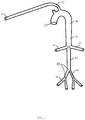
FIG. 1 shows a simplified arterial network model of a human being according to one specific embodiment of the present invention; -
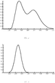
FIG. 2 shows a typical radial pulse measured at the wrist of a human subject; -
FIG. 3 shows an approximated aortic pulse according to one specific embodiment of the present invention; -
FIG. 4 shows a reconstructed impulse response based on the radial pulse as shown inFIG. 2 and the approximated aortic pulse as shown inFIG. 3 according to one specific embodiment of the present invention; -
FIG. 5 shows the three segments segmented from the reconstructed impulse response as shown inFIG. 4 according to one specific embodiment of the present invention; -
FIG. 6 shows the three components decomposed from the radial pulse as shown inFIG. 2 according to one specific embodiment of the present invention; -
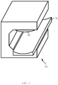
FIG. 7 is a schematic view of an arterial stiffness index measuring device according to one specific embodiment of the present invention; and -
FIG. 8 is a schematic configuration diagram of an arterial stiffness index measuring device according to one specific embodiment of the present invention. - As used herein and in the claims, "comprising" means including the following elements but not excluding others.
- As used herein and in the claims, "couple" or "connect" refers to electrical coupling or connection either directly or indirectly via one or more electrical means unless otherwise stated.
- Referring to
FIG. 1 , a simplified arterial network model of a human being according to one embodiment of the present invention is shown. The pulse waveform generated by the heart (not shown), also known as aortic pulse, first propagates along theaortic arch 20. When it reached the bifurcation betweenaortic arch 20 andbrachial artery 22, part of the aortic pulse will propagate to theradial artery 24 via thebrachial artery 22 and eventually measured by a sensor (not shown) placed near theradial artery 24. On the other hand, the rest of the aortic pulse continues to propagate down to thethoracic aorta 26 and upper abdominal aorta 28 until it reaches thefirst reflection site 32, which is the bifurcation between upper abdominal aorta 28 andrenal arteries 30. At thefirst reflection site 32, part of the aortic pulse will be reflected back and reaches theradial artery 24 via upper abdominal aorta 28,thoracic aorta 26 andbrachial artery 22; whereas the remaining aortic pulse will continue to propagate down to the lowerabdominal aorta 34 until it reaches thesecond reflection site 38 which is the bifurcation between lowerabdominal aorta 34 andiliac arteries 36. At thesecond reflection site 38, part of the aortic pulse will be reflected back to theradial artery 24 via lowerabdominal aorta 34, upper abdominal aorta 28,thoracic aorta 26 andbrachial artery 22; whereas the remaining aortic pulse will continue to propagate down to the lower limbs of the human being. It should be noted that the pulse waveform measured by the sensor near theradial artery 24, also known as radial pulse, includes three components: (1) originated from the heart and propagate directly to theradial artery 24; (2) reflected from thefirst reflection site 32; and (3) reflected from thesecond reflection site 38.FIG. 2 shows a typical radial pulse measured at the wrist of a human subject. - Mathematically, the aforesaid simplified arterial network model, which governs the relationship between the aortic pulse and the radial pulse, can be expressed by the equation (1).

aortic arch 20 directly to theradial artery 24 via thebrachial artery 22; (2) h2(t) which is the impulse response of the path fromaortic arch 20 to thefirst reflection site 32 and back to theradial artery 24 and (3) h 3(t) which is the impulse response of the path fromaortic arch 20 to thesecond reflection site 38 and back to theradial artery 24. - The method, according to one embodiment of the present invention, first constructs an approximated aortic pulse x(t) in the form of a Gaussian function based on the inflexion point of the first rising phase of the radial pulse y(t). The inflexion point is characterized by its value B and the slope S. These two parameters are calculated by setting the second derivative of the radial pulse y"(t) to zero and substituting the corresponding result back to the radial pulse y(t) and the first derivative of the radial pulse y'(t) respectively.
- The general form of a Gaussian function is expressed in the equation (2). The first derivative and the second derivative of the Gaussian function are shown in equation (3) and equation (4) respectively.


- In order to locate the inflexion point of a Gaussian function, the second derivative of the Gaussian function as shown in equation (4) is set to zero which yield the solution of t = -b or t = b. As such, the value and the slope at the inflexion point of the Gaussian function, which are the same as that of the radial pulse, are determined by equation (5) and equation (6) respectively. Based on the intermediate results of equation (5) and equation (6), the parameters A and b can be determined.


- By substituting the parameters A and b as shown in equation (5) and equation (6) back into equation (2), the approximated aortic pulse can be expressed as equation (7). The approximated aortic pulse x(t) obtained using equation (7) based on the radial pulse y(t) as shown in
FIG. 2 is shown inFIG. 3 .
- After obtaining the approximated aortic pulse x(t), the impulse response of the arterial network can be deconvoluted from the arterial network model as shown in equation (1). In matrix form, the arterial network model as shown in equation (1) can be rewritten as equation (8).

- However, it is impossible to find h directly as X is not invertible. According to one embodiment of the present invention, least square method as shown in equation (9) is used to obtain the impulse response h. The reconstructed impulse response obtained thereof based on the radial pulse as shown in
FIG. 2 and the approximated aortic pulse as shown inFIG. 3 is shown inFIG. 4 .
- After obtaining the reconstructed impulse response h of the arterial network, segmentation is employed to identify the three segments: (1) originated from the heart; (2) reflected from the
first reflection site 32; and (3) reflected from thesecond reflection site 38 of the impulse response h. In one embodiment of the present invention, the segmentation is conducted based on the anatomy of a human being. The travelling time of a pulse from the heart to thethoracic aorta 26, the upper abdominal aorta 28, the lowerabdominal aorta 34 andiliac arteries 36 are approximately 36 ms, 14 ms, 27 ms and 34 ms respectively. Therefore the time delay between the peak of the first component of the radial pulse and the peak of the second component of the radial pulse is 100 ms (i.e. the back and forth travelling time of thethoracic aorta 26 plus the back and forth travelling time of the upper abdominal aorta 28 is 2× (36 ms + 14 ms) = 100 ms) ; whereas the time delay between the peak of the first component of the radial pulse and the peak of the third component of the radial pulse is 222 ms (i.e. the back and forth travelling time of thethoracic aorta 26 plus the back and forth travelling time of the upper abdominal aorta 28 plus the back and forth travelling time of lowerabdominal aorta 34 plus the back and forth travelling time ofiliac arteries 36 is 2× (36 ms + 14 ms + 27 ms + 34 ms) = 222 ms). Based on the aforesaid time delays, the reconstructed impulse response h can be segmented in time domain into three segments, i.e. h 1(t), h 2(t) and h 3(t). The end point of each segment is defined as the local minimum point of the impulse response h with a predefined time interval. The time interval is based on the aforesaid time delays plus certain tolerance. In this embodiment, the end points of the first segment h 1(t) and the second segment h 2(t) are defined as the local minimum point of the impulse response h within 50 - 150 ms and 170 - 270 ms respectively. The corresponding segmentation result of the impulse response as indicated inFIG. 4 is shown inFIG. 5 , which shows the first segment 40 (from the start to 50 ms), the second segment 42 (from 50 ms to 210 ms) and the third segment 44 (beyond 210 ms). It should be noticed that, the impulse response h 1(t) is assumed to die down beyond the first segment 40 (i.e. h1(t) = 0 for t > 100 ms); the impulse response h 2(t) is zero in thefirst segment 40 and third segment 44 (i.e. h2(t) = 0 for 100 ms ≤ t < 444 ms) and the impulse response h 3(t) is zero in thefirst segment 40 and second segment 42(i.e. h 3(t) = 0 for t ≤ 444 ms). - With the
first segment 40, thesecond segment 42 and thethird segment 44 of the impulse response, the radial pulse can then be decomposed into three components based on equation (1), wherein the first component, the second component and the third component are x(t) ⊗ h 1(t), x(t) ⊗ h2 (t) and x(t) ⊗ h 3(t) respectively. The corresponding decomposed components of the radial pulse as indicated inFIG. 2 is shown inFIG. 6 , which shows thefirst component 46,second component 48 andthird component 50. The peak of thefirst component 46,second component 48 andthird component 50 are known as early systolic peak, late systolic peak and dias-tolic peak respectively. The arterial stiffness index is calculated as the ratio of the late systolic peak to the early systolic peak, i.e. the ratio of the peak of thesecond component 48 and that of thefirst component 46. The arterial stiffness index is positively correlated with various diseases, for instance coronary artery diseases, myocardial infarction, heart failure, hypertension, stroke, diabetes mellitus, end-stage renal disease, hypercholesterolemia and inflammation. - Referring now to
FIG. 7 , an arterial stiffnessindex measuring device 52 according to one embodiment of the present invention is shown. The arterial stiffnessindex measuring device 52 is of a C-shape. At the bottom side of the cavity surrounded by the C-shape structure is anarm holder 54. Thearm holder 54 has a convex upper surface configured to accept a human arm during operation. On the other hand, aninflatable cuff 56 is disposed at the upper side of the same cavity. As shown inFIG. 8 , there is a pressure sensor 58 disposed at the lower surface, which is the surface that would be in contact with thewrist 60 of the human subject during operation, of thecuff 56 thereby allowing the pressure sensor 58 to capture the radial pulse of human subject and transfer the same to themicroprocessor 62. Thecuff 56 is also in connection with apump 64, which is controlled by themicroprocessor 62. Themicroprocessor 62 is further coupled to a non-transitory computer-readable storage medium 66. Thestorage medium 66 is encoded with computer-readable instructions for causing themicroprocessor 62 to execute the steps of the method of determining the stiffness index of an arterial network as stated above. - During operation of the arterial stiffness
index measuring device 52, a person first puts his arm, with his palm facing upward, into the cavity of the arterial stiffnessindex measuring device 52 and rests on thearm holder 54. Themicroprocessor 62 will then activate thepump 64 to inflate thecuff 56. The pressure sensor 58 disposed with thecuff 56 is pushed against the radial artery of the person. The inflation process stops when a predefined pressure is achieved with thecuff 56. Subsequently, the pressure sensor 58 starts recording the radial pulse waveform and transfers the same to themicroprocessor 62. Thestorage medium 66 is encoded with computer-readable instructions for causingmicroprocessor 62 to calculate the arterial stiffness index based on the method as stated above. - The exemplary embodiments of the present invention are thus fully described. Although the description referred to particular embodiments and realizations, it will be clear to one skilled in the art that the present invention may be practiced with variation of these specific details. Hence this invention should not be construed as limited to the embodiments set forth herein.
- For instance, although wrist is chosen as the measurement of the pulse waveform, it should be obvious to one skilled in the art to notice that other measurement sites, for instance neck and thigh, could also be adopted in order to measure the corresponding pulse waveform. It should also be notice that, depending on the measurement sites, different arterial model will be adopted accordingly.
- Regarding the approximation of the aortic pulse, it is approximated to be a Gaussian function in the above-mentioned embodiments. Nonetheless, other bell shape functions, for instance log-normal and Rayleigh, could also be used to approximate the aortic pulse. Furthermore, the value and slope of the inflexion point of the first rising phase of the radial pulse are used as the basis in the approximation step. It should be clear to one skilled in the art that other methods can also be used. Moreover, other features of the first rising phase of the pulse waveform can be used in the approximation step, for instance the slope and values of any two arbitrary points within the first rising phase of the pulse waveform.
- Propagation time delays between components of the radial pulse are used in the segmentation of impulse response. However, the segmentation can be done by associating the impulse response segments with particular analytical functions and segmenting the impulse response accordingly. Other methodologies, for instance curve fitting and principal component analysis, could also be adopted. The travelling time of a pulse from the heart to the
thoracic aorta 26, the upper abdominal aorta 28, the lowerabdominal aorta 34 andiliac arteries 36 used can be within 10% of the above mentioned travelling time.
Claims (8)
- A method of determining a stiffness index of an arterial network of a human subject, comprising the steps of:a) using a pressure sensor (58) of an arterial stiffness index measuring device (52) to measure a radial pulse waveform y(t) related to said arterial network of the human subject, said pressure sensor (58) being configured to transfer the measured radial pulse waveform y(t) to a microprocessor (62);b) using said microprocessor (62) to model an approximated aortic pulse x(t) based on an inflexion point of a first rising phase of the measured radial pulse waveform y(t), the inflexion point being characterized by a value B and a slope S of a bell-shaped function, where B is the value of the inflexion point of a first rising phase of the measured radial pulse waveform y(t) and S is the slope of the same inflexion point;c) using said microprocessor (62) to reconstruct an impulse response h of the arterial network of the human subject by deconvolving the impulse response h of the arterial network using a least squares method from the measured radial pulse waveform y(t) and the approximated aortic pulse x(t);d) using the microprocessor (62) to segment the impulse response h of the arterial network into at least two segmented components h1(t) and h2(t) where h1(t) is a component of the impulse response h relating to direct propagation of the aortic pulse to the radial artery within the arterial network of the human subject and h2(t) is a component of the impulse response h relating to propagation of the aortic pulse from a first reflection site to the radial artery; ande) using the microprocessor (62) to calculate said stiffness index of said arterial network as a ratio of a peak of the second segmented component h2(t) to a peak of the first segmented component h1(t).
- The method of claim 1, wherein said pressure sensor (58) is disposed within a cuff (56) of the measuring device (52) and said cuff (56) is configured to surround a predefined portion of the human subject.
- The method of claim 1 or claim 2, wherein said approximated aortic pulse x(t) is in the form of a pulse shape function selected from a group consisting of a Gaussian function, a log-normal function and a Rayleigh function.
- The method of claim 3, wherein said approximated aortic pulse x(t) is in the form of a Gaussian function.
- The method of claim 4, wherein said step of segmenting said impulse response h is based on an anatomy of said arterial network.
- A system of determining a stiffness index of an arterial network of a human subject, comprising:a) a pressure sensor (58) of an arterial stiffness index measuring device (52), said pressure sensor (58) being configured to measure a radial pulse waveform y(t) related to said arterial network of the human subject;b) a microprocessor (62) being coupled to said pressure sensor (58); andc) a non-transitory computer-readable storage medium (66) coupled to said microprocessor (58), said non-transitory computer-readable storage medium (66) encoded with computer-readable instructions for causing said microprocessor (62) to execute the following steps:i. measure a radial pulse waveform y(t) related to said arterial network of the human subject and to transfer the measured radial pulse waveform y(t) to a microprocessor (62);ii. model an approximated aortic pulse x(t) based on an inflexion point of a first rising phase of the measured radial pulse waveform y(t), the inflexion point being characterized by a value B and a slope S of a bell-shaped function, where B is the value of the inflexion point of a first rising phase of the measured radial pulse waveform y(t) and S is the slope of the same inflexion point;iii. reconstruct an impulse response h of the arterial network of the human subject by deconvolving the impulse response h of the arterial network using a least squares method from the measured radial pulse waveform y(t) and the approximated aortic pulse x(t);iv. segmenting the impulse response h of the arterial network into at least two segmented components h1(t) and h2(t) where h1(t) is a component of the impulse response h relating to direct propagation of the aortic pulse to the radial artery within the arterial network of the human subject and h2(t) is a component of the impulse response h relating to propagation of the aortic pulse from a first reflection site to the radial artery; andv. calculating said stiffness index of said arterial network as a ratio of a peak of the second segmented component h2(t) to a peak of the first segmented component h1(t).
- The system of claim 6 further comprising:a) a cuff (56) of the measuring device (52) configured to surround a predefined portion of a subject; wherein said pressure sensor (58) is disposed within said cuff (56);b) a pump (64) coupled to said cuff (56) and said microprocessor (62);
wherein said non-transitory computer-readable storage medium (66) is further encoded with computer-readable instructions for causing said microprocessor (62) to activate said pump (64) to inflate said cuff (56) to fitly surround said predefined portion of said human subject, thereby measuring said radial pulse waveform y(t). - The system of claim 7, wherein said predefined portion is a wrist of said human subject.
Applications Claiming Priority (2)
| Application Number | Priority Date | Filing Date | Title |
|---|---|---|---|
| US14/289,649 US10058255B2 (en) | 2014-05-29 | 2014-05-29 | Method of determining stiffness index of an arterial network and system thereof |
| PCT/CN2015/078138 WO2015180554A1 (en) | 2014-05-29 | 2015-04-30 | Method of determining stiffness index of arterial network and system thereof |
Publications (3)
| Publication Number | Publication Date |
|---|---|
| EP3148421A1 EP3148421A1 (en) | 2017-04-05 |
| EP3148421A4 EP3148421A4 (en) | 2018-01-24 |
| EP3148421B1 true EP3148421B1 (en) | 2020-08-12 |
Family
ID=51872484
Family Applications (1)
| Application Number | Title | Priority Date | Filing Date |
|---|---|---|---|
| EP15799720.6A Not-in-force EP3148421B1 (en) | 2014-05-29 | 2015-04-30 | Method of determining stiffness index of arterial network and system thereof |
Country Status (4)
| Country | Link |
|---|---|
| US (1) | US10058255B2 (en) |
| EP (1) | EP3148421B1 (en) |
| CN (1) | CN104146692B (en) |
| WO (1) | WO2015180554A1 (en) |
Families Citing this family (3)
| Publication number | Priority date | Publication date | Assignee | Title |
|---|---|---|---|---|
| US10058255B2 (en) * | 2014-05-29 | 2018-08-28 | Hong Kong Applied Science And Technology Research Institute Co. Ltd. | Method of determining stiffness index of an arterial network and system thereof |
| CN104622440B (en) * | 2015-02-09 | 2018-02-09 | 中国科学院深圳先进技术研究院 | The method and device of punctuate during a kind of extraction pulse wave |
| US11402326B2 (en) | 2020-09-25 | 2022-08-02 | Hong Kong Applied Science And Technology Research Institute Co., Ltd. | Systems and methods for multi-wavelength scattering based smoke detection using multi-dimensional metric monitoring |
Family Cites Families (19)
| Publication number | Priority date | Publication date | Assignee | Title |
|---|---|---|---|---|
| GB2356251B (en) | 1999-11-12 | 2003-09-24 | Micro Medical Ltd | Apparatus for determining the stiffness of arteries in a person |
| US6616613B1 (en) * | 2000-04-27 | 2003-09-09 | Vitalsines International, Inc. | Physiological signal monitoring system |
| JP3590613B2 (en) | 2002-01-10 | 2004-11-17 | コーリンメディカルテクノロジー株式会社 | Amplitude increase index calculation device and arteriosclerosis test device |
| JP3643567B2 (en) * | 2002-04-17 | 2005-04-27 | コーリンメディカルテクノロジー株式会社 | Amplitude increase index measuring device |
| JP2004313468A (en) | 2003-04-16 | 2004-11-11 | Omron Healthcare Co Ltd | Pulse wave measuring apparatus and biological wave analysis program |
| JP4581496B2 (en) | 2004-06-14 | 2010-11-17 | オムロンヘルスケア株式会社 | Pulse wave analyzer and pulse wave analysis program |
| JP2006212155A (en) | 2005-02-02 | 2006-08-17 | Motoharu Hasegawa | Blood vessel hardening rate evaluating apparatus, blood vessel hardening index computing program and blood vessel hardening index computing method |
| EP2152151A2 (en) | 2007-05-01 | 2010-02-17 | Spirocor Ltd. | Method, apparatus and system for detection of arterial stiffness and artery tonus by pulse curve geometry analysis |
| TWI359006B (en) | 2008-04-18 | 2012-03-01 | Hsien Tsai Wu | A device and method for early blood vessel aging d |
| US9687161B2 (en) * | 2008-09-30 | 2017-06-27 | Nellcor Puritan Bennett Ireland | Systems and methods for maintaining blood pressure monitor calibration |
| KR101298838B1 (en) * | 2010-11-29 | 2013-08-23 | (주)더힘스 | Information providing method for arterial stiffness diagnosis |
| CN202458330U (en) | 2012-01-31 | 2012-10-03 | 许先崇 | Systemic atherosclerosis located detection device |
| US20150182132A1 (en) | 2012-08-10 | 2015-07-02 | Cnv Systems Ltd. | Mobile device system for measurement of cardiovascular health |
| US20140135632A1 (en) | 2012-11-15 | 2014-05-15 | Pulsecor Limited | Method and apparatus for determining cardiac medical parameters from supra-systolic signals obtained from an oscillometric blood pressure system |
| CN103070678A (en) | 2013-02-21 | 2013-05-01 | 沈阳恒德医疗器械研发有限公司 | Non-invasive central arterial pressure detector and detection method thereof |
| US10226188B2 (en) * | 2013-08-23 | 2019-03-12 | Covidien Lp | Systems and methods for monitoring blood pressure |
| CN103705224B (en) | 2013-11-06 | 2016-04-27 | 康尚医疗技术(丹阳)有限公司 | Arteriosclerosis measuring device |
| CN103690152B (en) | 2014-01-06 | 2016-04-20 | 山东大学 | A kind of arterial elasticity apparatus for evaluating based on pulse analytical |
| US10058255B2 (en) | 2014-05-29 | 2018-08-28 | Hong Kong Applied Science And Technology Research Institute Co. Ltd. | Method of determining stiffness index of an arterial network and system thereof |
-
2014
- 2014-05-29 US US14/289,649 patent/US10058255B2/en active Active
- 2014-06-18 CN CN201410273450.8A patent/CN104146692B/en active Active
-
2015
- 2015-04-30 WO PCT/CN2015/078138 patent/WO2015180554A1/en not_active Ceased
- 2015-04-30 EP EP15799720.6A patent/EP3148421B1/en not_active Not-in-force
Non-Patent Citations (1)
| Title |
|---|
| None * |
Also Published As
| Publication number | Publication date |
|---|---|
| WO2015180554A1 (en) | 2015-12-03 |
| US10058255B2 (en) | 2018-08-28 |
| CN104146692B (en) | 2016-06-22 |
| US20150342471A1 (en) | 2015-12-03 |
| EP3148421A1 (en) | 2017-04-05 |
| HK1203339A1 (en) | 2015-10-30 |
| EP3148421A4 (en) | 2018-01-24 |
| CN104146692A (en) | 2014-11-19 |
Similar Documents
| Publication | Publication Date | Title |
|---|---|---|
| US10709424B2 (en) | Method and system for cuff-less blood pressure (BP) measurement of a subject | |
| CN106028917B (en) | Method for determining pulse wave velocity in an artery | |
| EP3102100B1 (en) | Apparatuses for determining blood pressure | |
| Nabeel et al. | Single-source PPG-based local pulse wave velocity measurement: a potential cuffless blood pressure estimation technique | |
| EP3474749B1 (en) | Dynamic calibration of a blood pressure measurement device | |
| Segers et al. | Limitations and pitfalls of non-invasive measurement of arterial pressure wave reflections and pulse wave velocity | |
| US10398323B2 (en) | Methods and apparatus for determining pulse transit time as a function of blood pressure | |
| EP3133985B1 (en) | A method and a device for non invasive blood pressure measurement | |
| CN102499658B (en) | Central blood pressure waveform reconstruction module and reconstruction method | |
| CN107992452B (en) | Method, device, storage medium and equipment for calculating central hemodynamics index | |
| CN110141196A (en) | Peripheral arterial vessel elasticity evaluation method and system based on double triangle blood flow model | |
| CN101925331A (en) | Method and apparatus to determine the end of systolic part of pressure curve | |
| CN103445808A (en) | Main artery non-invasive continuous blood pressure measuring method and device thereof | |
| EP2675349A1 (en) | A method of and a system for determining a cardiovascular quantity of a mammal | |
| US12059234B2 (en) | Method and a system for estimating a measure of cardiovascular health of a subject | |
| JP7438617B2 (en) | Signal restoration system, signal restoration method, and program for causing a computer to execute the signal restoration method | |
| US10058255B2 (en) | Method of determining stiffness index of an arterial network and system thereof | |
| IL189943A (en) | Signal processing for pulse oximetry | |
| Joseph et al. | ARTSENS® Pen: A portable, image-free device for automated evaluation of vascular stiffness | |
| Pereira et al. | Characterization of a double probe for local pulse wave velocity assessment | |
| CN109480802B (en) | A blood pressure parameter estimation system and method based on waveform analysis technology | |
| JP2019058653A (en) | Pulse wave velocity measurement apparatus | |
| HK1203339B (en) | System of determining the stiffness index of an arterial network | |
| JP2006122380A (en) | Ultrasonic diagnostic apparatus | |
| Sakamoto et al. | Radar-based Measurement of Pulse Wave using Fast Physiological Component Analysis |
Legal Events
| Date | Code | Title | Description |
|---|---|---|---|
| STAA | Information on the status of an ep patent application or granted ep patent |
Free format text: STATUS: THE INTERNATIONAL PUBLICATION HAS BEEN MADE |
|
| PUAI | Public reference made under article 153(3) epc to a published international application that has entered the european phase |
Free format text: ORIGINAL CODE: 0009012 |
|
| STAA | Information on the status of an ep patent application or granted ep patent |
Free format text: STATUS: REQUEST FOR EXAMINATION WAS MADE |
|
| 17P | Request for examination filed |
Effective date: 20161209 |
|
| AK | Designated contracting states |
Kind code of ref document: A1 Designated state(s): AL AT BE BG CH CY CZ DE DK EE ES FI FR GB GR HR HU IE IS IT LI LT LU LV MC MK MT NL NO PL PT RO RS SE SI SK SM TR |
|
| AX | Request for extension of the european patent |
Extension state: BA ME |
|
| DAV | Request for validation of the european patent (deleted) | ||
| DAX | Request for extension of the european patent (deleted) | ||
| A4 | Supplementary search report drawn up and despatched |
Effective date: 20180103 |
|
| RIC1 | Information provided on ipc code assigned before grant |
Ipc: A61B 5/02 20060101AFI20171220BHEP |
|
| STAA | Information on the status of an ep patent application or granted ep patent |
Free format text: STATUS: EXAMINATION IS IN PROGRESS |
|
| 17Q | First examination report despatched |
Effective date: 20180820 |
|
| GRAP | Despatch of communication of intention to grant a patent |
Free format text: ORIGINAL CODE: EPIDOSNIGR1 |
|
| STAA | Information on the status of an ep patent application or granted ep patent |
Free format text: STATUS: GRANT OF PATENT IS INTENDED |
|
| INTG | Intention to grant announced |
Effective date: 20200326 |
|
| GRAS | Grant fee paid |
Free format text: ORIGINAL CODE: EPIDOSNIGR3 |
|
| GRAA | (expected) grant |
Free format text: ORIGINAL CODE: 0009210 |
|
| STAA | Information on the status of an ep patent application or granted ep patent |
Free format text: STATUS: THE PATENT HAS BEEN GRANTED |
|
| AK | Designated contracting states |
Kind code of ref document: B1 Designated state(s): AL AT BE BG CH CY CZ DE DK EE ES FI FR GB GR HR HU IE IS IT LI LT LU LV MC MK MT NL NO PL PT RO RS SE SI SK SM TR |
|
| REG | Reference to a national code |
Ref country code: CH Ref legal event code: EP |
|
| REG | Reference to a national code |
Ref country code: IE Ref legal event code: FG4D |
|
| REG | Reference to a national code |
Ref country code: DE Ref legal event code: R096 Ref document number: 602015057425 Country of ref document: DE |
|
| REG | Reference to a national code |
Ref country code: AT Ref legal event code: REF Ref document number: 1300717 Country of ref document: AT Kind code of ref document: T Effective date: 20200915 |
|
| REG | Reference to a national code |
Ref country code: LT Ref legal event code: MG4D |
|
| REG | Reference to a national code |
Ref country code: NL Ref legal event code: MP Effective date: 20200812 |
|
| PG25 | Lapsed in a contracting state [announced via postgrant information from national office to epo] |
Ref country code: FI Free format text: LAPSE BECAUSE OF FAILURE TO SUBMIT A TRANSLATION OF THE DESCRIPTION OR TO PAY THE FEE WITHIN THE PRESCRIBED TIME-LIMIT Effective date: 20200812 Ref country code: GR Free format text: LAPSE BECAUSE OF FAILURE TO SUBMIT A TRANSLATION OF THE DESCRIPTION OR TO PAY THE FEE WITHIN THE PRESCRIBED TIME-LIMIT Effective date: 20201113 Ref country code: NO Free format text: LAPSE BECAUSE OF FAILURE TO SUBMIT A TRANSLATION OF THE DESCRIPTION OR TO PAY THE FEE WITHIN THE PRESCRIBED TIME-LIMIT Effective date: 20201112 Ref country code: BG Free format text: LAPSE BECAUSE OF FAILURE TO SUBMIT A TRANSLATION OF THE DESCRIPTION OR TO PAY THE FEE WITHIN THE PRESCRIBED TIME-LIMIT Effective date: 20201112 Ref country code: SE Free format text: LAPSE BECAUSE OF FAILURE TO SUBMIT A TRANSLATION OF THE DESCRIPTION OR TO PAY THE FEE WITHIN THE PRESCRIBED TIME-LIMIT Effective date: 20200812 Ref country code: HR Free format text: LAPSE BECAUSE OF FAILURE TO SUBMIT A TRANSLATION OF THE DESCRIPTION OR TO PAY THE FEE WITHIN THE PRESCRIBED TIME-LIMIT Effective date: 20200812 Ref country code: LT Free format text: LAPSE BECAUSE OF FAILURE TO SUBMIT A TRANSLATION OF THE DESCRIPTION OR TO PAY THE FEE WITHIN THE PRESCRIBED TIME-LIMIT Effective date: 20200812 |
|
| REG | Reference to a national code |
Ref country code: AT Ref legal event code: MK05 Ref document number: 1300717 Country of ref document: AT Kind code of ref document: T Effective date: 20200812 |
|
| PG25 | Lapsed in a contracting state [announced via postgrant information from national office to epo] |
Ref country code: NL Free format text: LAPSE BECAUSE OF FAILURE TO SUBMIT A TRANSLATION OF THE DESCRIPTION OR TO PAY THE FEE WITHIN THE PRESCRIBED TIME-LIMIT Effective date: 20200812 Ref country code: LV Free format text: LAPSE BECAUSE OF FAILURE TO SUBMIT A TRANSLATION OF THE DESCRIPTION OR TO PAY THE FEE WITHIN THE PRESCRIBED TIME-LIMIT Effective date: 20200812 Ref country code: PL Free format text: LAPSE BECAUSE OF FAILURE TO SUBMIT A TRANSLATION OF THE DESCRIPTION OR TO PAY THE FEE WITHIN THE PRESCRIBED TIME-LIMIT Effective date: 20200812 Ref country code: RS Free format text: LAPSE BECAUSE OF FAILURE TO SUBMIT A TRANSLATION OF THE DESCRIPTION OR TO PAY THE FEE WITHIN THE PRESCRIBED TIME-LIMIT Effective date: 20200812 Ref country code: IS Free format text: LAPSE BECAUSE OF FAILURE TO SUBMIT A TRANSLATION OF THE DESCRIPTION OR TO PAY THE FEE WITHIN THE PRESCRIBED TIME-LIMIT Effective date: 20201212 |
|
| PG25 | Lapsed in a contracting state [announced via postgrant information from national office to epo] |
Ref country code: DK Free format text: LAPSE BECAUSE OF FAILURE TO SUBMIT A TRANSLATION OF THE DESCRIPTION OR TO PAY THE FEE WITHIN THE PRESCRIBED TIME-LIMIT Effective date: 20200812 Ref country code: CZ Free format text: LAPSE BECAUSE OF FAILURE TO SUBMIT A TRANSLATION OF THE DESCRIPTION OR TO PAY THE FEE WITHIN THE PRESCRIBED TIME-LIMIT Effective date: 20200812 Ref country code: EE Free format text: LAPSE BECAUSE OF FAILURE TO SUBMIT A TRANSLATION OF THE DESCRIPTION OR TO PAY THE FEE WITHIN THE PRESCRIBED TIME-LIMIT Effective date: 20200812 Ref country code: RO Free format text: LAPSE BECAUSE OF FAILURE TO SUBMIT A TRANSLATION OF THE DESCRIPTION OR TO PAY THE FEE WITHIN THE PRESCRIBED TIME-LIMIT Effective date: 20200812 Ref country code: SM Free format text: LAPSE BECAUSE OF FAILURE TO SUBMIT A TRANSLATION OF THE DESCRIPTION OR TO PAY THE FEE WITHIN THE PRESCRIBED TIME-LIMIT Effective date: 20200812 |
|
| REG | Reference to a national code |
Ref country code: DE Ref legal event code: R097 Ref document number: 602015057425 Country of ref document: DE |
|
| PG25 | Lapsed in a contracting state [announced via postgrant information from national office to epo] |
Ref country code: ES Free format text: LAPSE BECAUSE OF FAILURE TO SUBMIT A TRANSLATION OF THE DESCRIPTION OR TO PAY THE FEE WITHIN THE PRESCRIBED TIME-LIMIT Effective date: 20200812 Ref country code: AT Free format text: LAPSE BECAUSE OF FAILURE TO SUBMIT A TRANSLATION OF THE DESCRIPTION OR TO PAY THE FEE WITHIN THE PRESCRIBED TIME-LIMIT Effective date: 20200812 Ref country code: AL Free format text: LAPSE BECAUSE OF FAILURE TO SUBMIT A TRANSLATION OF THE DESCRIPTION OR TO PAY THE FEE WITHIN THE PRESCRIBED TIME-LIMIT Effective date: 20200812 |
|
| PLBE | No opposition filed within time limit |
Free format text: ORIGINAL CODE: 0009261 |
|
| STAA | Information on the status of an ep patent application or granted ep patent |
Free format text: STATUS: NO OPPOSITION FILED WITHIN TIME LIMIT |
|
| PG25 | Lapsed in a contracting state [announced via postgrant information from national office to epo] |
Ref country code: SK Free format text: LAPSE BECAUSE OF FAILURE TO SUBMIT A TRANSLATION OF THE DESCRIPTION OR TO PAY THE FEE WITHIN THE PRESCRIBED TIME-LIMIT Effective date: 20200812 |
|
| 26N | No opposition filed |
Effective date: 20210514 |
|
| PG25 | Lapsed in a contracting state [announced via postgrant information from national office to epo] |
Ref country code: IT Free format text: LAPSE BECAUSE OF FAILURE TO SUBMIT A TRANSLATION OF THE DESCRIPTION OR TO PAY THE FEE WITHIN THE PRESCRIBED TIME-LIMIT Effective date: 20200812 |
|
| PG25 | Lapsed in a contracting state [announced via postgrant information from national office to epo] |
Ref country code: SI Free format text: LAPSE BECAUSE OF FAILURE TO SUBMIT A TRANSLATION OF THE DESCRIPTION OR TO PAY THE FEE WITHIN THE PRESCRIBED TIME-LIMIT Effective date: 20200812 |
|
| PG25 | Lapsed in a contracting state [announced via postgrant information from national office to epo] |
Ref country code: MC Free format text: LAPSE BECAUSE OF FAILURE TO SUBMIT A TRANSLATION OF THE DESCRIPTION OR TO PAY THE FEE WITHIN THE PRESCRIBED TIME-LIMIT Effective date: 20200812 |
|
| GBPC | Gb: european patent ceased through non-payment of renewal fee |
Effective date: 20210430 |
|
| PG25 | Lapsed in a contracting state [announced via postgrant information from national office to epo] |
Ref country code: LU Free format text: LAPSE BECAUSE OF NON-PAYMENT OF DUE FEES Effective date: 20210430 |
|
| REG | Reference to a national code |
Ref country code: BE Ref legal event code: MM Effective date: 20210430 |
|
| PG25 | Lapsed in a contracting state [announced via postgrant information from national office to epo] |
Ref country code: LI Free format text: LAPSE BECAUSE OF NON-PAYMENT OF DUE FEES Effective date: 20210430 Ref country code: CH Free format text: LAPSE BECAUSE OF NON-PAYMENT OF DUE FEES Effective date: 20210430 Ref country code: GB Free format text: LAPSE BECAUSE OF NON-PAYMENT OF DUE FEES Effective date: 20210430 Ref country code: FR Free format text: LAPSE BECAUSE OF NON-PAYMENT OF DUE FEES Effective date: 20210430 |
|
| PG25 | Lapsed in a contracting state [announced via postgrant information from national office to epo] |
Ref country code: IE Free format text: LAPSE BECAUSE OF NON-PAYMENT OF DUE FEES Effective date: 20210430 |
|
| PG25 | Lapsed in a contracting state [announced via postgrant information from national office to epo] |
Ref country code: IS Free format text: LAPSE BECAUSE OF FAILURE TO SUBMIT A TRANSLATION OF THE DESCRIPTION OR TO PAY THE FEE WITHIN THE PRESCRIBED TIME-LIMIT Effective date: 20201212 |
|
| PG25 | Lapsed in a contracting state [announced via postgrant information from national office to epo] |
Ref country code: BE Free format text: LAPSE BECAUSE OF NON-PAYMENT OF DUE FEES Effective date: 20210430 |
|
| PG25 | Lapsed in a contracting state [announced via postgrant information from national office to epo] |
Ref country code: PT Free format text: LAPSE BECAUSE OF FAILURE TO SUBMIT A TRANSLATION OF THE DESCRIPTION OR TO PAY THE FEE WITHIN THE PRESCRIBED TIME-LIMIT Effective date: 20201214 |
|
| PG25 | Lapsed in a contracting state [announced via postgrant information from national office to epo] |
Ref country code: HU Free format text: LAPSE BECAUSE OF FAILURE TO SUBMIT A TRANSLATION OF THE DESCRIPTION OR TO PAY THE FEE WITHIN THE PRESCRIBED TIME-LIMIT; INVALID AB INITIO Effective date: 20150430 |
|
| PG25 | Lapsed in a contracting state [announced via postgrant information from national office to epo] |
Ref country code: CY Free format text: LAPSE BECAUSE OF FAILURE TO SUBMIT A TRANSLATION OF THE DESCRIPTION OR TO PAY THE FEE WITHIN THE PRESCRIBED TIME-LIMIT Effective date: 20200812 |
|
| PGFP | Annual fee paid to national office [announced via postgrant information from national office to epo] |
Ref country code: DE Payment date: 20230420 Year of fee payment: 9 |
|
| PG25 | Lapsed in a contracting state [announced via postgrant information from national office to epo] |
Ref country code: MK Free format text: LAPSE BECAUSE OF FAILURE TO SUBMIT A TRANSLATION OF THE DESCRIPTION OR TO PAY THE FEE WITHIN THE PRESCRIBED TIME-LIMIT Effective date: 20200812 |
|
| PG25 | Lapsed in a contracting state [announced via postgrant information from national office to epo] |
Ref country code: TR Free format text: LAPSE BECAUSE OF FAILURE TO SUBMIT A TRANSLATION OF THE DESCRIPTION OR TO PAY THE FEE WITHIN THE PRESCRIBED TIME-LIMIT Effective date: 20200812 |
|
| PG25 | Lapsed in a contracting state [announced via postgrant information from national office to epo] |
Ref country code: MT Free format text: LAPSE BECAUSE OF FAILURE TO SUBMIT A TRANSLATION OF THE DESCRIPTION OR TO PAY THE FEE WITHIN THE PRESCRIBED TIME-LIMIT Effective date: 20200812 |
|
| REG | Reference to a national code |
Ref country code: DE Ref legal event code: R119 Ref document number: 602015057425 Country of ref document: DE |
|
| PG25 | Lapsed in a contracting state [announced via postgrant information from national office to epo] |
Ref country code: DE Free format text: LAPSE BECAUSE OF NON-PAYMENT OF DUE FEES Effective date: 20251104 |