EP3148354B1 - Smoking article with ventilated mouth end cavity - Google Patents
Smoking article with ventilated mouth end cavity Download PDFInfo
- Publication number
- EP3148354B1 EP3148354B1 EP15725049.9A EP15725049A EP3148354B1 EP 3148354 B1 EP3148354 B1 EP 3148354B1 EP 15725049 A EP15725049 A EP 15725049A EP 3148354 B1 EP3148354 B1 EP 3148354B1
- Authority
- EP
- European Patent Office
- Prior art keywords
- filter
- hollow tube
- smoking article
- tube segment
- segment
- Prior art date
- Legal status (The legal status is an assumption and is not a legal conclusion. Google has not performed a legal analysis and makes no representation as to the accuracy of the status listed.)
- Active
Links
- 230000000391 smoking effect Effects 0.000 title claims description 103
- 238000009423 ventilation Methods 0.000 claims description 26
- 241000208125 Nicotiana Species 0.000 claims description 22
- 235000002637 Nicotiana tabacum Nutrition 0.000 claims description 22
- 238000011144 upstream manufacturing Methods 0.000 claims description 12
- 239000000853 adhesive Substances 0.000 claims description 5
- 230000001070 adhesive effect Effects 0.000 claims description 5
- 238000004891 communication Methods 0.000 claims description 3
- 239000000463 material Substances 0.000 description 23
- 239000000779 smoke Substances 0.000 description 17
- 239000010410 layer Substances 0.000 description 15
- 238000012360 testing method Methods 0.000 description 13
- 238000001914 filtration Methods 0.000 description 9
- 230000006835 compression Effects 0.000 description 8
- 238000007906 compression Methods 0.000 description 8
- 239000000443 aerosol Substances 0.000 description 7
- 239000000796 flavoring agent Substances 0.000 description 7
- 238000013461 design Methods 0.000 description 6
- 239000002775 capsule Substances 0.000 description 5
- 238000012546 transfer Methods 0.000 description 5
- OKTJSMMVPCPJKN-UHFFFAOYSA-N Carbon Chemical compound [C] OKTJSMMVPCPJKN-UHFFFAOYSA-N 0.000 description 4
- 239000000654 additive Substances 0.000 description 4
- 230000000996 additive effect Effects 0.000 description 4
- 229910052799 carbon Inorganic materials 0.000 description 4
- 238000004519 manufacturing process Methods 0.000 description 4
- 238000000034 method Methods 0.000 description 4
- 238000010521 absorption reaction Methods 0.000 description 3
- 239000000945 filler Substances 0.000 description 3
- 238000010438 heat treatment Methods 0.000 description 3
- 238000000265 homogenisation Methods 0.000 description 3
- 230000001965 increasing effect Effects 0.000 description 3
- 238000005259 measurement Methods 0.000 description 3
- 239000000758 substrate Substances 0.000 description 3
- 238000010998 test method Methods 0.000 description 3
- SNICXCGAKADSCV-JTQLQIEISA-N (-)-Nicotine Chemical compound CN1CCC[C@H]1C1=CC=CN=C1 SNICXCGAKADSCV-JTQLQIEISA-N 0.000 description 2
- 239000003463 adsorbent Substances 0.000 description 2
- 229920002301 cellulose acetate Polymers 0.000 description 2
- 239000011247 coating layer Substances 0.000 description 2
- 150000001875 compounds Chemical class 0.000 description 2
- 235000019634 flavors Nutrition 0.000 description 2
- 238000002156 mixing Methods 0.000 description 2
- 239000000203 mixture Substances 0.000 description 2
- 229960002715 nicotine Drugs 0.000 description 2
- SNICXCGAKADSCV-UHFFFAOYSA-N nicotine Natural products CN1CCCC1C1=CC=CN=C1 SNICXCGAKADSCV-UHFFFAOYSA-N 0.000 description 2
- 239000001993 wax Substances 0.000 description 2
- 101100493705 Caenorhabditis elegans bath-36 gene Proteins 0.000 description 1
- 239000001856 Ethyl cellulose Substances 0.000 description 1
- ZZSNKZQZMQGXPY-UHFFFAOYSA-N Ethyl cellulose Chemical compound CCOCC1OC(OC)C(OCC)C(OCC)C1OC1C(O)C(O)C(OC)C(CO)O1 ZZSNKZQZMQGXPY-UHFFFAOYSA-N 0.000 description 1
- 239000000020 Nitrocellulose Substances 0.000 description 1
- 230000004888 barrier function Effects 0.000 description 1
- 238000006243 chemical reaction Methods 0.000 description 1
- 235000019504 cigarettes Nutrition 0.000 description 1
- 239000011248 coating agent Substances 0.000 description 1
- 238000000576 coating method Methods 0.000 description 1
- 238000002485 combustion reaction Methods 0.000 description 1
- 239000006185 dispersion Substances 0.000 description 1
- 230000002708 enhancing effect Effects 0.000 description 1
- 229920001249 ethyl cellulose Polymers 0.000 description 1
- 229960004667 ethyl cellulose Drugs 0.000 description 1
- 235000019325 ethyl cellulose Nutrition 0.000 description 1
- 239000012530 fluid Substances 0.000 description 1
- 239000000446 fuel Substances 0.000 description 1
- 238000003384 imaging method Methods 0.000 description 1
- 230000002045 lasting effect Effects 0.000 description 1
- 229920001220 nitrocellulos Polymers 0.000 description 1
- 230000035699 permeability Effects 0.000 description 1
- 239000004014 plasticizer Substances 0.000 description 1
- 230000001737 promoting effect Effects 0.000 description 1
- 238000005507 spraying Methods 0.000 description 1
- 230000032258 transport Effects 0.000 description 1
- 239000012178 vegetable wax Substances 0.000 description 1
- 238000004804 winding Methods 0.000 description 1
Images
Classifications
-
- A—HUMAN NECESSITIES
- A24—TOBACCO; CIGARS; CIGARETTES; SIMULATED SMOKING DEVICES; SMOKERS' REQUISITES
- A24D—CIGARS; CIGARETTES; TOBACCO SMOKE FILTERS; MOUTHPIECES FOR CIGARS OR CIGARETTES; MANUFACTURE OF TOBACCO SMOKE FILTERS OR MOUTHPIECES
- A24D3/00—Tobacco smoke filters, e.g. filter-tips, filtering inserts; Filters specially adapted for simulated smoking devices; Mouthpieces for cigars or cigarettes
- A24D3/02—Manufacture of tobacco smoke filters
- A24D3/0275—Manufacture of tobacco smoke filters for filters with special features
- A24D3/0291—Manufacture of tobacco smoke filters for filters with special features for hollow tipped filters, e.g. recess filters
-
- A—HUMAN NECESSITIES
- A24—TOBACCO; CIGARS; CIGARETTES; SIMULATED SMOKING DEVICES; SMOKERS' REQUISITES
- A24D—CIGARS; CIGARETTES; TOBACCO SMOKE FILTERS; MOUTHPIECES FOR CIGARS OR CIGARETTES; MANUFACTURE OF TOBACCO SMOKE FILTERS OR MOUTHPIECES
- A24D1/00—Cigars; Cigarettes
- A24D1/02—Cigars; Cigarettes with special covers
- A24D1/027—Cigars; Cigarettes with special covers with ventilating means, e.g. perforations
-
- A—HUMAN NECESSITIES
- A24—TOBACCO; CIGARS; CIGARETTES; SIMULATED SMOKING DEVICES; SMOKERS' REQUISITES
- A24D—CIGARS; CIGARETTES; TOBACCO SMOKE FILTERS; MOUTHPIECES FOR CIGARS OR CIGARETTES; MANUFACTURE OF TOBACCO SMOKE FILTERS OR MOUTHPIECES
- A24D1/00—Cigars; Cigarettes
- A24D1/04—Cigars; Cigarettes with mouthpieces or filter-tips
- A24D1/042—Cigars; Cigarettes with mouthpieces or filter-tips with mouthpieces
-
- A—HUMAN NECESSITIES
- A24—TOBACCO; CIGARS; CIGARETTES; SIMULATED SMOKING DEVICES; SMOKERS' REQUISITES
- A24D—CIGARS; CIGARETTES; TOBACCO SMOKE FILTERS; MOUTHPIECES FOR CIGARS OR CIGARETTES; MANUFACTURE OF TOBACCO SMOKE FILTERS OR MOUTHPIECES
- A24D3/00—Tobacco smoke filters, e.g. filter-tips, filtering inserts; Filters specially adapted for simulated smoking devices; Mouthpieces for cigars or cigarettes
- A24D3/04—Tobacco smoke filters characterised by their shape or structure
- A24D3/043—Tobacco smoke filters characterised by their shape or structure with ventilation means, e.g. air dilution
Definitions
- the present invention relates to a smoking article having a mouth end cavity defined by a hollow tube segment.
- Filter cigarettes typically comprise a cylindrical rod of tobacco cut filler surrounded by a paper wrapper and a cylindrical filter axially aligned in an abutting end-to-end relationship with the wrapped tobacco rod.
- the cylindrical filter typically comprises a filtration material circumscribed by a paper plug wrap.
- the wrapped tobacco rod and the filter are joined by a band of tipping wrapper, normally formed of an opaque paper material that circumscribes the entire length of the filter and an adjacent portion of the wrapped tobacco rod.
- Smoking articles having a cavity at the mouth end of their filter section have also been proposed.
- a number of smoking articles in which tobacco is heated rather than combusted have also been proposed in the art.
- heated smoking articles an aerosol is generated by heating an aerosol generating substrate, such as tobacco.
- Known heated smoking articles include, for example, smoking articles in which an aerosol is generated by electrical heating or by the transfer of heat from a combustible fuel element or heat source to an aerosol forming substrate.
- volatile compounds are released from the aerosol forming substrate by heat transfer from the heat source and entrained in air drawn through the smoking article. As the released compounds cool they condense to form an aerosol that is inhaled by the consumer.
- smoking articles in which a nicotine-containing aerosol is generated from a tobacco material, tobacco extract or other nicotine source, without combustion and in some cases without heating, for example through a chemical reaction.
- a smoking article comprising a filter having a hollow tubular element at the mouth end is known from US 2009/0293894 .
- the hollow tubular element may be formed when the filter is attached to a rod of smokable material by tipping paper.
- the hollow tubular element preferably includes a cylindrical element, such as a carbon tube, that is overwrapped by the tipping material to provide additional strength to the filter.
- a method of manufacturing a smoking articles comprising a hollow tube segment defines a cavity at the mouth end of the filter is known from WO 2014/023555 .
- a filtered smoking article having a mouth end cavity which is adapted to promote homogenization of the mainstream smoke prior to it reaching the mouth of the consumer.
- the present invention provides a smoking article comprising a tobacco rod and a filter connected to the tobacco rod.
- the filter comprises at least a first filter segment and a hollow tube segment downstream of the first filter segment.
- the hollow tube segment defines a cavity at the mouth end of the filter providing an unrestricted flow channel that extends from the downstream end of the first filter segment to the mouth end of the filter.
- the length of the hollow tube segment is at least about 25 percent and less than about 50 percent of the overall filter length.
- the smoking article comprises a ventilation zone in communication with the cavity at a location along the hollow tube segment. The ventilation zone is located from about 10 mm to about 15 mm upstream from the mouth end of the filter.
- upstream and downstream are used to describe the relative positions of elements, or portions of elements, of the smoking article in relation to the direction in which a consumer draws on the smoking article during use thereof.
- Smoking articles as described herein comprise a downstream end and an opposed upstream end. In use, a consumer draws on the downstream end of the smoking article.
- the downstream end which is also described as the mouth end, is downstream of the upstream end, which may also be described as the distal end.
- unrestricted flow is used throughout this specification to indicate that the hollow tube segment internally defines a channel having a substantially constant cross-sectional area for the smoke and air to flow through.
- the expression “unrestricted flow channel” is used throughout this specification to indicate that the hollow tube segment does not contain any object which may cause a local restriction of the flow of the smoke and air. In other words, the hollow tube segment is empty.
- the cross-sectional area available for the smoke and air to flow through is substantially constant along the whole length of the hollow tube segment and flow of smoke and air through the hollow tube segment is substantially unobstructed.
- all filter length is used throughout this specification to refer to the sum of the length of the various components forming the filter.
- all filter length should be construed as referring at least to the sum of the length of the hollow tube segment and the length of the first filter segment.
- the expression “overall filter length” should be construed as referring to the sum of the length of the hollow tube segment and the length of each of the other filter segments in the smoking article.
- a filter comprising an unrestricted hollow tube segment and a ventilation zone having the features specified above advantageously enables the production of smoking articles in which an improved dispersion of air and mainstream smoke at the mouth end is achieved.
- a ventilation zone in communication with the unrestricted channel internally defined by the hollow tube is understood to promote turbulent flow of air and mainstream smoke through the filter of the smoking article and, in particular, at the downstream end of the filter.
- turbulent flows favour the homogenization of fluid mixtures by enhancing the rates of mass, momentum and energy transports in a flow.
- the hollow segment represents at least 25 percent, and less than about 50 percent, of the overall length of the filter, the air drawn into the filter via the ventilation zone and the mainstream smoke are provided room for intimately mixing under turbulent flow conditions prior to leaving the filter.
- a better dispersed flow of air and mainstream smoke advantageously reaches the mouth of the consumer.
- the length of the filter segment or segments upstream of the hollow tube segment thus accounts for at least about 50 percent of the overall filter length.
- the unrestricted, hollow tube segment does not substantially contribute to increasing the resistance to draw (RTD) of the smoking article. At most, the unrestricted, hollow tube segment contributes only marginally to increasing the RTD of the smoking article.
- the unrestricted, hollow tube segment may be adapted to generate a RTD in the range of approximately 1 mm H 2 O (about 10 Pa) and approximately 20 mm H 2 O (about 200 Pa).
- the unrestricted, hollow tube segment is adapted to generate a RTD between approximately 2 mm H 2 O (about 20 Pa) and approximately 10 mm H 2 O (about 100 Pa).
- the filter segment or segments upstream of the unrestricted, hollow tube segment account for at least about 50 percent of the overall filter length, it is advantageously possible, by selecting filtration material or materials of appropriate density and characteristics, to adjust the overall RTD of the smoking article to satisfactory levels. In some preferred embodiments, the filter segment or segments upstream of the unrestricted, hollow tube segment account for at least about 60 percent of the overall filter length.
- the length of the hollow tube segment is less than about 25 mm.
- the length of the hollow tube segment is less than about 15 mm.
- the length of the hollow tube segment is at least about 10 mm.
- the length of the hollow tube segment is from about 10 mm to about 15 mm. This not only provides a mouth end cavity and an unrestricted flow channel of an appropriate size, but also ensures sufficient overlap between the hollow tube segment and any wrapper which may circumscribe the hollow tube segment to maintain it in axial alignment with the filter segment or with the tobacco rod or with both.
- wrappers include plug wraps and tipping paper bands.
- the ventilation zone is located at least about 10 mm upstream from the mouth end of the filter. This advantageously makes it less likely for the consumer to obstruct the ventilation zone when holding the smoking article with his or her lips..
- the ventilation zone is located less than about 15 mm upstream from the mouth end of the filter. Having the ventilation zone located from about 10 mm to about 15 mm upstream from the mouth end of the filter provides a highly appropriate length of unrestricted flow channel for the air and smoke to flow through under turbulent conditions and, therefore, to thoroughly mix before they reach the mouth end of the smoking article.
- the ventilation zone is located at least about 1 mm downstream from the downstream end of the first filter segment, preferably at least about 2 mm downstream from the downstream end of the first filter segment. More preferably, the ventilation zone is located at least about 5 mm downstream from the downstream end of the first filter segment. Even more preferably, the ventilation zone is located at least about 10 mm downstream from the downstream end of the first filter segment.
- the ventilation zone comprises at least one circumferential row of perforations provided through the hollow tube segment.
- the ventilation zone comprises two circumferential rows of perforations provided through the hollow tube segment.
- the perforations may be formed online during manufacture of the smoking article.
- each circumferential row of perforations comprises from 8 to 30 perforations.
- the tobacco rod typically comprises a charge of tobacco cut filler circumscribed by a paper wrapper.
- the hollow tube segment and the filter segment or segments are circumscribed by a band of plug wrap.
- the hollow tube segment and the filter segment or segments are circumscribed by a band of impermeable plug wrap.
- the hollow tube segment and filter segment or segments are circumscribed by a band of substantially air permeable plug wrap, more preferably a band of plug wrap having a permeability of between about 7,000 Coresta units and about 20,000 Coresta units.
- the plug wrap may have a basis weight of less than about 120 gsm, preferably less than about 100 gsm, more preferably less than about 80 gsm. In addition, or as an alternative, the plug wrap may have a basis weight of at least about 20 gsm, preferably at least about 25 gsm. The combining plug wrap preferably has a basis weight of more than about 20 gsm.
- the band of plug wrap may be affixed to the hollow tube segment and the filter segment or segments using, for example, an adhesive.
- the ventilation zone preferably comprises at least one circumferential row of perforations provided through a portion of the plug wrap.
- the perforations through the plug wrap may be formed online during manufacture of the smoking article.
- the circumferential row or rows of perforations provided through a portion of the plug wrap are in substantial alignment with the corresponding row or rows of perforations provided through the hollow tube segment.
- the filter comprising the band of plug wrap is preferably attached to the tobacco rod by a band of substantially impermeable tipping paper.
- the tipping wrapper may comprise paper having a basis weight of less than about 70 gsm, preferably less than about 50 gsm.
- the tipping wrapper preferably has a basis weight of more than about 20 gsm.
- the band of tipping paper may extend over the whole length of the filter and over a portion of the tobacco rod.
- the band of tipping paper may overlap ventilation perforations provided through the hollow tube segment.
- the band of tipping paper may extend over only a portion of the filter and over a portion of the tobacco rod, that is substantially at the junction of filter and tobacco rod.
- the band of tipping paper may not overlap ventilation perforations provided through the hollow tube segment.
- the smoking article comprises a band of tipping paper that extends over ventilation perforations provided through the hollow tube segment and/or the filter plug wrap
- the band of tipping paper also comprises one or more rows of ventilation perforations.
- the circumferential row or rows of perforations provided through the tipping paper are in substantial alignment with the corresponding row or rows of perforations provided through the hollow tube segment and/or the filter plug wrap.
- smoking articles according to the present invention may comprise additional filter segments in combination with the first filter segment.
- the smoking article further comprises a rod end segment of filtration material between the first filter segment and the tobacco rod.
- the filtration material within each filter segment of the smoking article is preferably a plug of fibrous filtration material, such as cellulose acetate tow or paper.
- a filter plasticiser may be applied to the fibrous filtration material in a conventional manner, by spraying it onto the separated fibres, preferably before applying any additional material to the filtration material.
- smoking articles in accordance with the present invention may include one or more segments containing carbon, preferably a rod end segment containing carbon.
- the hollow tube segment is preferably formed from a paper material. More preferably, the hollow tube segment is formed from a plurality of overlapping paper layers, such as a plurality of parallel wound paper layers or a plurality of spirally wound paper layers. Forming the hollow tube segment from a plurality of overlapping paper layers can help to improve resistance to collapse or deformation.
- each hollow tube segment comprises at least two paper layers.
- each hollow tube segment preferably comprises fewer than eleven paper layers.
- the wall thickness of the hollow tube segment is at least about 90 micrometres. More preferably, the wall thickness of the hollow tube segment is at least about 100 micrometres. Alternatively, or in addition, the wall thickness of the hollow tube segment is less than about 140 micrometres. Preferably, the wall thickness of the hollow tube segment is less than about 130 micrometres. In some preferred embodiments, the wall thickness of the hollow tube segment is from about 90 micrometres to about 140 micrometres, preferably from 100 micrometres to 130 micrometres.
- An exemplary method for forming a tube segment from a plurality of wound paper layers comprises wrapping a plurality of substantially continuous paper strips in an overlapping manner about a cylindrical mandrel. The strips are wrapped in a parallel manner or a spiral manner so as to form a substantially continuous tube on the mandrel.
- the formed tube may be turned about the mandrel, for example using a rubber belt, so that the paper layers are continually drawn and wrapped around the mandrel. The formed tube can then be cut into the required lengths downstream of the mandrel.
- the resistance of the hollow tube segment to collapse or deformation may be such that the difference between the ovality of the tube segment after 50 percent deformation of the filter and the ovality of the tube segment prior to deformation is less than about 25 percent, preferably less than about 20 percent.
- the ovality of the tube segment prior to deformation is 5 percent
- the ovality of the tube segment after a 50 percent deformation of the filter is preferably less than 30 percent, more preferably less than 25 percent.
- the mouth end is viewed along the longitudinal direction of the smoking article.
- the smoking article can be positioned on its mouth end on a transparent stage so that an image of the mouth end of the article is recorded by a suitable imaging device located below the stage.
- Dimension "a” is taken to be the smallest external diameter of the segment at its downstream end and dimension "b" is taken to be the largest external diameter of the segment at its downstream end.
- the ovality of the hollow tube segment after a 50 percent deformation is preferably less than about 25 percent, more preferably less than about 20 percent.
- the mouth end cavity of smoking articles in accordance with the present invention will retain or resume a generally circular cross section, even after a 50 percent deformation of the filter.
- the ovality of the tube segment after a 67 percent deformation of the filter is preferably less than about 35 percent, more preferably less than about 30 percent.
- the ovality of the hollow tube segment after a 50 percent deformation of the filter performed after the smoking article has been subjected to a smoking test is preferably less than about 35 percent, more preferably less than about 30 percent.
- the ovality of the tube segment after a 67 percent deformation of the filter performed after the smoking article has been subjected to a smoking test is preferably less than about 45 percent, more preferably less than about 40 percent. This advantageously provides consistency in the ovality of the mouth end cavity during smoking of the smoking article.
- the smoking test used for testing smoking articles in accordance with the present invention is described in detail below. Where it is necessary to measure the ovality after deformation tests performed both before and after smoking, two samples of smoking articles having the same design should be used. That is, a non-deformed un-smoked smoking article should be used for the pre-smoking deformation test, and non-deformed articles having the same design are subjected to the smoking test and used for the post-smoking deformation test.
- the hollow tube segment may comprise a coating layer on an inner surface thereof, which can inhibit absorption of moisture into the hollow tube segment.
- a coating layer may additionally or alternatively be provided between some or all of the adjacent paper layers.
- Suitable coating materials include, but are not limited to, waxes, polymeric materials and combinations thereof. Particularly suitable waxes include vegetable waxes, and other particularly suitable materials are ethyl-cellulose and nitrocellulose.
- the filter preferably has an un-smoked compressive strength of at least about 20 Newtons at 50 percent compression.
- the un-smoked compressive strength of the filter at 50 percent compression is preferably less than about 50 Newtons.
- the term "compressive strength" is a measure of the force required to provide a particular compression of the filter section of the smoking article. Compressive strength is measured using the compressive strength test described in detail below, where the compressive strength of a given smoking article design is the number average of the compressive strength measurements for a sample of ten smoking articles having the same design.
- the filter may comprise at least one filter segment including a flavourant containing material, such as, for example, one or more breakable capsules comprising an outer shell and an inner core containing an additive.
- a flavourant containing material such as, for example, one or more breakable capsules comprising an outer shell and an inner core containing an additive.
- the at least one filter segment comprises one or more breakable capsules dispersed within a fibrous filtration material.
- the at least one filter segment may be the first filter segment, or an additional filter segment which may be incorporated into the filter, or a combination thereof.
- the at least one flavour containing filter segment is preferably circumscribed by a plug wrap that is substantially impermeable to the flavourant additive. This advantageously inhibits transfer of the additive through the plug wrap to the outside of the smoking article, where it may undesirably come into contact with the consumer's fingers and may tarnish the appearance of the smoking article.
- the smoking article to be tested is positioned between a flat surface and a circular plate opposed to the flat surface, the circular plate having a diameter of 10 mm.
- the of the circular plate closest to the mouth end of the smoking article is positioned 8 mm from the mouth end.
- the filter is then compressed by moving the circular plate towards the flat surface at a constant speed of 100 mm per second.
- the force applied by the circular plate is increased until the desired deformation of the portion of the smoking article between the circular plate and the flat surface is achieved. For example, to achieve a 50 percent deformation, the compressed portion of the smoking article is compressed to a diameter of 50 percent of the diameter of that portion prior to compression.
- the smoking article is compressed until the compressed portion is reduced to a diameter of 33 percent of the diameter of that portion prior to compression.
- the diameter is measured in the direction of compression, which is the direction extending between the flat surface and the circular plate.
- the smoking article is subjected to a standard smoking test under ISO conditions (35 ml puffs lasting 2 seconds each, every 60 seconds).
- the smoking article is smoked with the ventilation zone fully uncovered.
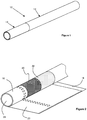
- FIGS 1 and 2 illustrate a smoking article 10 in accordance with the present invention.
- the smoking article 10 comprises a wrapped rod 12 of tobacco cut filler which is attached at one end to an axially aligned filter 14.
- a band of tipping paper 16 circumscribes the filter 14 and a portion of the wrapped rod 12 of tobacco to join together the two portions of the smoking article 10.
- the filter 14 comprises a hollow tube segment 18, a first filter segment 20, which may or may not contain flavour, and a rod end filter segment 22.
- the hollow tube segment 18 and the filter segments 20 and 22 are circumscribed by a band of combining plug wrap 23 which connects the three segments to form the filter 14.
- One or more of the segments 18, 20, 22 may additionally be wrapped in an individual plug wrap.
- the first filter segment 20 and the rod end filter segment 22 are formed of a suitable filtration material, such as cellulose acetate tow. Furthermore, the first filter segment may comprise a suitable flavourant, which may be provided in the form of one or more breakable capsules contained within the first filter segment 20. In this case, the one or more breakable capsules are ruptured by the consumer when desired by squeezing the first filter segment 20 between the consumer's fingers.
- the rod end filter segment 22 contains an adsorbent material, such as a carbon-based adsorbent material.
- the hollow tube segment 18 defines a mouth end cavity 24 in the filter 14 and provides an unrestricted flow channel which extends between the downstream end of the first filter segment 20 and the mouth end of the filter 14.
- the hollow tube segment 18 internally defines a channel having a substantially constant cross-sectional area for the smoke and air to flow through.
- the hollow tube segment 18 does not contain any object adapted to cause a local restriction of the flow of the smoke and air.
- the cross-sectional area available for the smoke and air to flow through is substantially constant along the whole length of the hollow tube segment 18 and flow of smoke and air through the hollow tube segment 18 is unobstructed.
- the length of the hollow tube segment 18 is about 35 percent of the overall filter length. Further, the hollow tube segment 18 may have a wall thickness from about 100 micrometres to about 130 micrometres.
- the hollow tube segment 18 may be formed of a plurality of spirally wound paper layers which can further improve the resistance to deformation of the mouth end cavity 24, for example during smoking or during rupture of the one or more breakable capsules when present in the first filter segment 20.
- the ovality of the hollow tube segment after a 50 percent deformation of the filter 14 may be less than 25 percent.
- the smoking article 10 further comprises a ventilation zone 26 at a location along the hollow tube segment 18.
- the ventilation zone 26 comprises two rows of perforations extending through the wall of the hollow tube segment 18. Two rows of perforations also extend through the band of combining plug wrap 23 and through the band of tipping paper 16. The rows of perforations extending through the band of combining plug wrap 23 and through the band of tipping paper 16 are substantially aligned with those extending through the wall of the hollow tube segment 18.
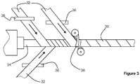
- Figure 3 shows an exemplary method of forming a hollow tube member 30 which can be cut to form a plurality of hollow tube segments for use in forming smoking articles in accordance with the present invention.
- a plurality of continuous paper plies 32 are spirally wound around a cylindrical mandrel 34 in a staggered, overlapping arrangement.
- a suitable adhesive may be applied to one or more of the plies 32 using an adhesive bath 36 prior to winding each ply around the mandrel 34.
- the plies 32 are driven by a rubber belt 38 so that the formed tubular member 30 rotates around the mandrel 34 until it is cut into desired lengths further downstream.
Description
- The present invention relates to a smoking article having a mouth end cavity defined by a hollow tube segment.
- Filter cigarettes typically comprise a cylindrical rod of tobacco cut filler surrounded by a paper wrapper and a cylindrical filter axially aligned in an abutting end-to-end relationship with the wrapped tobacco rod. The cylindrical filter typically comprises a filtration material circumscribed by a paper plug wrap. Conventionally, the wrapped tobacco rod and the filter are joined by a band of tipping wrapper, normally formed of an opaque paper material that circumscribes the entire length of the filter and an adjacent portion of the wrapped tobacco rod. Smoking articles having a cavity at the mouth end of their filter section have also been proposed.
- A number of smoking articles in which tobacco is heated rather than combusted have also been proposed in the art. In heated smoking articles, an aerosol is generated by heating an aerosol generating substrate, such as tobacco. Known heated smoking articles include, for example, smoking articles in which an aerosol is generated by electrical heating or by the transfer of heat from a combustible fuel element or heat source to an aerosol forming substrate. During smoking, volatile compounds are released from the aerosol forming substrate by heat transfer from the heat source and entrained in air drawn through the smoking article. As the released compounds cool they condense to form an aerosol that is inhaled by the consumer. Also known are smoking articles in which a nicotine-containing aerosol is generated from a tobacco material, tobacco extract or other nicotine source, without combustion and in some cases without heating, for example through a chemical reaction.
- A smoking article comprising a filter having a hollow tubular element at the mouth end is known from
US 2009/0293894 . The hollow tubular element may be formed when the filter is attached to a rod of smokable material by tipping paper. However, the hollow tubular element preferably includes a cylindrical element, such as a carbon tube, that is overwrapped by the tipping material to provide additional strength to the filter. A method of manufacturing a smoking articles comprising a hollow tube segment defines a cavity at the mouth end of the filter is known fromWO 2014/023555 . - It would be desirable to provide a filtered smoking article having a mouth end cavity which is adapted to promote homogenization of the mainstream smoke prior to it reaching the mouth of the consumer.
- Accordingly, the present invention provides a smoking article comprising a tobacco rod and a filter connected to the tobacco rod. The filter comprises at least a first filter segment and a hollow tube segment downstream of the first filter segment. The hollow tube segment defines a cavity at the mouth end of the filter providing an unrestricted flow channel that extends from the downstream end of the first filter segment to the mouth end of the filter. The length of the hollow tube segment is at least about 25 percent and less than about 50 percent of the overall filter length. Further, the smoking article comprises a ventilation zone in communication with the cavity at a location along the hollow tube segment. The ventilation zone is located from about 10 mm to about 15 mm upstream from the mouth end of the filter.
- As used herein, the terms "upstream" and "downstream" are used to describe the relative positions of elements, or portions of elements, of the smoking article in relation to the direction in which a consumer draws on the smoking article during use thereof. Smoking articles as described herein comprise a downstream end and an opposed upstream end. In use, a consumer draws on the downstream end of the smoking article. The downstream end, which is also described as the mouth end, is downstream of the upstream end, which may also be described as the distal end.
- The expression "unrestricted flow" is used throughout this specification to indicate that the hollow tube segment internally defines a channel having a substantially constant cross-sectional area for the smoke and air to flow through. Further, the expression "unrestricted flow channel" is used throughout this specification to indicate that the hollow tube segment does not contain any object which may cause a local restriction of the flow of the smoke and air. In other words, the hollow tube segment is empty. Thus, the cross-sectional area available for the smoke and air to flow through is substantially constant along the whole length of the hollow tube segment and flow of smoke and air through the hollow tube segment is substantially unobstructed.
- The expression "overall filter length" is used throughout this specification to refer to the sum of the length of the various components forming the filter. Thus, the expression "overall filter length" should be construed as referring at least to the sum of the length of the hollow tube segment and the length of the first filter segment. Similarly, if the smoking article comprises more than one filter segments upstream of the hollow tube segment, the expression "overall filter length" should be construed as referring to the sum of the length of the hollow tube segment and the length of each of the other filter segments in the smoking article.
- According to the present invention, the inclusion of a filter comprising an unrestricted hollow tube segment and a ventilation zone having the features specified above advantageously enables the production of smoking articles in which an improved dispersion of air and mainstream smoke at the mouth end is achieved. Without wishing to be bound to theory, the provision of a ventilation zone in communication with the unrestricted channel internally defined by the hollow tube is understood to promote turbulent flow of air and mainstream smoke through the filter of the smoking article and, in particular, at the downstream end of the filter. As is known, turbulent flows favour the homogenization of fluid mixtures by enhancing the rates of mass, momentum and energy transports in a flow. Because the hollow segment represents at least 25 percent, and less than about 50 percent, of the overall length of the filter, the air drawn into the filter via the ventilation zone and the mainstream smoke are provided room for intimately mixing under turbulent flow conditions prior to leaving the filter. Thus, in smoking articles in accordance with the present invention, a better dispersed flow of air and mainstream smoke advantageously reaches the mouth of the consumer.
- Further, the length of the filter segment or segments upstream of the hollow tube segment thus accounts for at least about 50 percent of the overall filter length. The unrestricted, hollow tube segment does not substantially contribute to increasing the resistance to draw (RTD) of the smoking article. At most, the unrestricted, hollow tube segment contributes only marginally to increasing the RTD of the smoking article. In practice, the unrestricted, hollow tube segment may be adapted to generate a RTD in the range of approximately 1 mm H2O (about 10 Pa) and approximately 20 mm H2O (about 200 Pa). Preferably, the unrestricted, hollow tube segment is adapted to generate a RTD between approximately 2 mm H2O (about 20 Pa) and approximately 10 mm H2O (about 100 Pa). Because the filter segment or segments upstream of the unrestricted, hollow tube segment account for at least about 50 percent of the overall filter length, it is advantageously possible, by selecting filtration material or materials of appropriate density and characteristics, to adjust the overall RTD of the smoking article to satisfactory levels. In some preferred embodiments, the filter segment or segments upstream of the unrestricted, hollow tube segment account for at least about 60 percent of the overall filter length.
- Preferably, the length of the hollow tube segment is less than about 25 mm. Preferably, the length of the hollow tube segment is less than about 15 mm. In addition, or as an alternative, the length of the hollow tube segment is at least about 10 mm. In some preferred embodiments, the length of the hollow tube segment is from about 10 mm to about 15 mm. This not only provides a mouth end cavity and an unrestricted flow channel of an appropriate size, but also ensures sufficient overlap between the hollow tube segment and any wrapper which may circumscribe the hollow tube segment to maintain it in axial alignment with the filter segment or with the tobacco rod or with both. Such wrappers include plug wraps and tipping paper bands.
- The ventilation zone is located at least about 10 mm upstream from the mouth end of the filter. This advantageously makes it less likely for the consumer to obstruct the ventilation zone when holding the smoking article with his or her lips..
- In addition, the ventilation zone is located less than about 15 mm upstream from the mouth end of the filter. Having the ventilation zone located from about 10 mm to about 15 mm upstream from the mouth end of the filter provides a highly appropriate length of unrestricted flow channel for the air and smoke to flow through under turbulent conditions and, therefore, to thoroughly mix before they reach the mouth end of the smoking article.
- In addition, or as an alternative, the ventilation zone is located at least about 1 mm downstream from the downstream end of the first filter segment, preferably at least about 2 mm downstream from the downstream end of the first filter segment. More preferably, the ventilation zone is located at least about 5 mm downstream from the downstream end of the first filter segment. Even more preferably, the ventilation zone is located at least about 10 mm downstream from the downstream end of the first filter segment. Thus, the air being drawn into the cavity defined by the hollow tube segment in a substantially radial direction encounters the mainstream smoke flowing into the cavity from the first filter segment substantially along an axial direction. Without wishing to be bound to theory, this is understood to favour dragging of the air drawn into the cavity on the part of the mainstream smoke flowing in the axial direction, thus further promoting thorough mixing and homogenization of air and mainstream smoke within the cavity.
- Preferably, the ventilation zone comprises at least one circumferential row of perforations provided through the hollow tube segment. In some preferred embodiments, the ventilation zone comprises two circumferential rows of perforations provided through the hollow tube segment. For example, the perforations may be formed online during manufacture of the smoking article. Preferably, each circumferential row of perforations comprises from 8 to 30 perforations.
- The tobacco rod typically comprises a charge of tobacco cut filler circumscribed by a paper wrapper.
- The hollow tube segment and the filter segment or segments are circumscribed by a band of plug wrap. Preferably, the hollow tube segment and the filter segment or segments are circumscribed by a band of impermeable plug wrap. In an alternative embodiment, the hollow tube segment and filter segment or segments are circumscribed by a band of substantially air permeable plug wrap, more preferably a band of plug wrap having a permeability of between about 7,000 Coresta units and about 20,000 Coresta units.
- The plug wrap may have a basis weight of less than about 120 gsm, preferably less than about 100 gsm, more preferably less than about 80 gsm. In addition, or as an alternative, the plug wrap may have a basis weight of at least about 20 gsm, preferably at least about 25 gsm. The combining plug wrap preferably has a basis weight of more than about 20 gsm.
- The band of plug wrap may be affixed to the hollow tube segment and the filter segment or segments using, for example, an adhesive. Where the filter comprises a band of substantially air impermeable plug wrap, the ventilation zone preferably comprises at least one circumferential row of perforations provided through a portion of the plug wrap. By way of example, the perforations through the plug wrap may be formed online during manufacture of the smoking article. Preferably, the circumferential row or rows of perforations provided through a portion of the plug wrap are in substantial alignment with the corresponding row or rows of perforations provided through the hollow tube segment.
- The filter comprising the band of plug wrap is preferably attached to the tobacco rod by a band of substantially impermeable tipping paper. The tipping wrapper may comprise paper having a basis weight of less than about 70 gsm, preferably less than about 50 gsm. The tipping wrapper preferably has a basis weight of more than about 20 gsm.
- The band of tipping paper may extend over the whole length of the filter and over a portion of the tobacco rod. Thus, the band of tipping paper may overlap ventilation perforations provided through the hollow tube segment. As an alternative, the band of tipping paper may extend over only a portion of the filter and over a portion of the tobacco rod, that is substantially at the junction of filter and tobacco rod. Thus, at least in some embodiments, the band of tipping paper may not overlap ventilation perforations provided through the hollow tube segment.
- Where the smoking article comprises a band of tipping paper that extends over ventilation perforations provided through the hollow tube segment and/or the filter plug wrap, the band of tipping paper also comprises one or more rows of ventilation perforations. Preferably, the circumferential row or rows of perforations provided through the tipping paper are in substantial alignment with the corresponding row or rows of perforations provided through the hollow tube segment and/or the filter plug wrap.
- As mentioned above, smoking articles according to the present invention may comprise additional filter segments in combination with the first filter segment. For example, in one embodiment, the smoking article further comprises a rod end segment of filtration material between the first filter segment and the tobacco rod.
- The filtration material within each filter segment of the smoking article is preferably a plug of fibrous filtration material, such as cellulose acetate tow or paper. A filter plasticiser may be applied to the fibrous filtration material in a conventional manner, by spraying it onto the separated fibres, preferably before applying any additional material to the filtration material. Alternatively, or in addition, smoking articles in accordance with the present invention may include one or more segments containing carbon, preferably a rod end segment containing carbon.
- The hollow tube segment is preferably formed from a paper material. More preferably, the hollow tube segment is formed from a plurality of overlapping paper layers, such as a plurality of parallel wound paper layers or a plurality of spirally wound paper layers. Forming the hollow tube segment from a plurality of overlapping paper layers can help to improve resistance to collapse or deformation.
- Preferably each hollow tube segment comprises at least two paper layers. Alternatively, or additionally, each hollow tube segment preferably comprises fewer than eleven paper layers.
- Preferably, the wall thickness of the hollow tube segment is at least about 90 micrometres. More preferably, the wall thickness of the hollow tube segment is at least about 100 micrometres. Alternatively, or in addition, the wall thickness of the hollow tube segment is less than about 140 micrometres. Preferably, the wall thickness of the hollow tube segment is less than about 130 micrometres. In some preferred embodiments, the wall thickness of the hollow tube segment is from about 90 micrometres to about 140 micrometres, preferably from 100 micrometres to 130 micrometres.
- An exemplary method for forming a tube segment from a plurality of wound paper layers comprises wrapping a plurality of substantially continuous paper strips in an overlapping manner about a cylindrical mandrel. The strips are wrapped in a parallel manner or a spiral manner so as to form a substantially continuous tube on the mandrel. The formed tube may be turned about the mandrel, for example using a rubber belt, so that the paper layers are continually drawn and wrapped around the mandrel. The formed tube can then be cut into the required lengths downstream of the mandrel.
- One factor that may restrict the ability of the hollow tube segment to retain its ovality during smoking of the smoking article is absorption of moisture into the tube segment during smoking. Therefore, to inhibit the transfer of moisture from one paper layer to the next during smoking of the smoking article, adjacent paper layers of each tubular member are preferably adhered together by an intermediate layer of adhesive, which provides a barrier to the transfer of moisture between layers.
- In any of the embodiments described above, the resistance of the hollow tube segment to collapse or deformation may be such that the difference between the ovality of the tube segment after 50 percent deformation of the filter and the ovality of the tube segment prior to deformation is less than about 25 percent, preferably less than about 20 percent. For example, where the ovality of the tube segment prior to deformation is 5 percent, the ovality of the tube segment after a 50 percent deformation of the filter is preferably less than 30 percent, more preferably less than 25 percent. The particular test procedure for conducting deformations of the filter in accordance with present invention is described in detail below.
- The term "ovality" as used herein means the degree of deviation from a perfect circle. Ovality is expressed as a percentage and the mathematical definition is given below.


- To determine the ovality of a segment of a smoking article (such as a hollow tube segment) in accordance with the present invention, the mouth end is viewed along the longitudinal direction of the smoking article. For example, the smoking article can be positioned on its mouth end on a transparent stage so that an image of the mouth end of the article is recorded by a suitable imaging device located below the stage. Dimension "a" is taken to be the smallest external diameter of the segment at its downstream end and dimension "b" is taken to be the largest external diameter of the segment at its downstream end. The process is repeated for a total of ten smoking articles having the same design and the number average of the ten ovality measurements is recorded as the ovality for that design of smoking article.
- Since smoking article filters are generally circular in cross section, the ovality of the hollow tube segment after a 50 percent deformation is preferably less than about 25 percent, more preferably less than about 20 percent. In this case, the mouth end cavity of smoking articles in accordance with the present invention will retain or resume a generally circular cross section, even after a 50 percent deformation of the filter. Alternatively, or in addition, the ovality of the tube segment after a 67 percent deformation of the filter is preferably less than about 35 percent, more preferably less than about 30 percent.
- In some embodiments, the ovality of the hollow tube segment after a 50 percent deformation of the filter performed after the smoking article has been subjected to a smoking test is preferably less than about 35 percent, more preferably less than about 30 percent. Alternatively, or in addition, the ovality of the tube segment after a 67 percent deformation of the filter performed after the smoking article has been subjected to a smoking test is preferably less than about 45 percent, more preferably less than about 40 percent. This advantageously provides consistency in the ovality of the mouth end cavity during smoking of the smoking article.
- The smoking test used for testing smoking articles in accordance with the present invention is described in detail below. Where it is necessary to measure the ovality after deformation tests performed both before and after smoking, two samples of smoking articles having the same design should be used. That is, a non-deformed un-smoked smoking article should be used for the pre-smoking deformation test, and non-deformed articles having the same design are subjected to the smoking test and used for the post-smoking deformation test.
- As discussed above, one factor that may restrict the ability of the hollow tube segment to retain its ovality during smoking of the smoking article is absorption of moisture into the tube segment. Therefore, the hollow tube segment may comprise a coating layer on an inner surface thereof, which can inhibit absorption of moisture into the hollow tube segment. In those embodiments in which the hollow tube segment is formed from a plurality of paper layers, a coating layer may additionally or alternatively be provided between some or all of the adjacent paper layers. Suitable coating materials include, but are not limited to, waxes, polymeric materials and combinations thereof. Particularly suitable waxes include vegetable waxes, and other particularly suitable materials are ethyl-cellulose and nitrocellulose.
- To increase the resistance of the hollow tube segment to crushing, the filter preferably has an un-smoked compressive strength of at least about 20 Newtons at 50 percent compression. Alternatively, or in addition, the un-smoked compressive strength of the filter at 50 percent compression is preferably less than about 50 Newtons. The term "compressive strength" is a measure of the force required to provide a particular compression of the filter section of the smoking article. Compressive strength is measured using the compressive strength test described in detail below, where the compressive strength of a given smoking article design is the number average of the compressive strength measurements for a sample of ten smoking articles having the same design.
- In some embodiments, it may be desirable to provide the filter with means for releasing a flavourant or other additive on demand, usually via manual release by the consumer immediately prior to smoking the article. Therefore, the filter may comprise at least one filter segment including a flavourant containing material, such as, for example, one or more breakable capsules comprising an outer shell and an inner core containing an additive. Preferably the at least one filter segment comprises one or more breakable capsules dispersed within a fibrous filtration material. The at least one filter segment may be the first filter segment, or an additional filter segment which may be incorporated into the filter, or a combination thereof.
- In embodiments comprising a flavourant containing material, the at least one flavour containing filter segment is preferably circumscribed by a plug wrap that is substantially impermeable to the flavourant additive. This advantageously inhibits transfer of the additive through the plug wrap to the outside of the smoking article, where it may undesirably come into contact with the consumer's fingers and may tarnish the appearance of the smoking article.
- The smoking article to be tested is positioned between a flat surface and a circular plate opposed to the flat surface, the circular plate having a diameter of 10 mm. The of the circular plate closest to the mouth end of the smoking article is positioned 8 mm from the mouth end. The filter is then compressed by moving the circular plate towards the flat surface at a constant speed of 100 mm per second. The force applied by the circular plate is increased until the desired deformation of the portion of the smoking article between the circular plate and the flat surface is achieved. For example, to achieve a 50 percent deformation, the compressed portion of the smoking article is compressed to a diameter of 50 percent of the diameter of that portion prior to compression. Similarly, to achieve a 67 percent deformation, the smoking article is compressed until the compressed portion is reduced to a diameter of 33 percent of the diameter of that portion prior to compression. The diameter is measured in the direction of compression, which is the direction extending between the flat surface and the circular plate. Once the desired compression has been achieved, the force required to provide that compression is noted as the compressive strength of the filter. The circular plate is then retracted so that the compressive force is removed. The smoking article is left for 30 seconds to expand before any further tests or measurements are performed.
- To simulate the smoking of a smoking article, the smoking article is subjected to a standard smoking test under ISO conditions (35 ml puffs lasting 2 seconds each, every 60 seconds). In the ISO test method, the smoking article is smoked with the ventilation zone fully uncovered.
- The invention will now be further described, by way of example only, with reference to the accompanying drawings in which:
-
Figure 1 shows a smoking article in accordance with the present invention; -
Figure 2 shows the mouth end of the smoking article ofFigure 1 with the filter unwrapped; and -
Figure 3 shows an exemplary method of forming a tubular member for forming hollow tube segments in accordance with the present invention. -
Figures 1 and 2 illustrate asmoking article 10 in accordance with the present invention. Thesmoking article 10 comprises a wrappedrod 12 of tobacco cut filler which is attached at one end to an axially alignedfilter 14. A band of tippingpaper 16 circumscribes thefilter 14 and a portion of the wrappedrod 12 of tobacco to join together the two portions of thesmoking article 10. - As shown in
Figure 2 , thefilter 14 comprises ahollow tube segment 18, afirst filter segment 20, which may or may not contain flavour, and a rodend filter segment 22. Thehollow tube segment 18 and thefilter segments filter 14. One or more of thesegments - The
first filter segment 20 and the rodend filter segment 22 are formed of a suitable filtration material, such as cellulose acetate tow. Furthermore, the first filter segment may comprise a suitable flavourant, which may be provided in the form of one or more breakable capsules contained within thefirst filter segment 20. In this case, the one or more breakable capsules are ruptured by the consumer when desired by squeezing thefirst filter segment 20 between the consumer's fingers. The rodend filter segment 22 contains an adsorbent material, such as a carbon-based adsorbent material. - The
hollow tube segment 18 defines amouth end cavity 24 in thefilter 14 and provides an unrestricted flow channel which extends between the downstream end of thefirst filter segment 20 and the mouth end of thefilter 14. In more detail, thehollow tube segment 18 internally defines a channel having a substantially constant cross-sectional area for the smoke and air to flow through. Further, thehollow tube segment 18 does not contain any object adapted to cause a local restriction of the flow of the smoke and air. Thus, the cross-sectional area available for the smoke and air to flow through is substantially constant along the whole length of thehollow tube segment 18 and flow of smoke and air through thehollow tube segment 18 is unobstructed. - In the embodiment of
Figures 1 and 2 , the length of thehollow tube segment 18 is about 35 percent of the overall filter length. Further, thehollow tube segment 18 may have a wall thickness from about 100 micrometres to about 130 micrometres. - The
hollow tube segment 18 may be formed of a plurality of spirally wound paper layers which can further improve the resistance to deformation of themouth end cavity 24, for example during smoking or during rupture of the one or more breakable capsules when present in thefirst filter segment 20. The ovality of the hollow tube segment after a 50 percent deformation of thefilter 14 may be less than 25 percent. - The
smoking article 10 further comprises a ventilation zone 26 at a location along thehollow tube segment 18. In more detail, the ventilation zone 26 comprises two rows of perforations extending through the wall of thehollow tube segment 18. Two rows of perforations also extend through the band of combiningplug wrap 23 and through the band of tippingpaper 16. The rows of perforations extending through the band of combiningplug wrap 23 and through the band of tippingpaper 16 are substantially aligned with those extending through the wall of thehollow tube segment 18. -
Figure 3 shows an exemplary method of forming ahollow tube member 30 which can be cut to form a plurality of hollow tube segments for use in forming smoking articles in accordance with the present invention. A plurality of continuous paper plies 32 are spirally wound around acylindrical mandrel 34 in a staggered, overlapping arrangement. A suitable adhesive may be applied to one or more of theplies 32 using anadhesive bath 36 prior to winding each ply around themandrel 34. Theplies 32 are driven by arubber belt 38 so that the formedtubular member 30 rotates around themandrel 34 until it is cut into desired lengths further downstream.
Claims (13)
- A smoking article (10) comprising:a tobacco rod (12); anda filter (14) connected to the tobacco rod (12), the filter (14) comprising:a first filter segment (20); anda hollow tube segment (18) downstream of the first filter segment (20), the hollow tube segment (18) defining a cavity (24) at the mouth end of the filter providing an unrestricted flow channel that extends from the downstream end of the first filter segment to the mouth end of the filter,wherein the length of the hollow tube segment (18) is at least 25 percent, and less than 50 percent, of the overall filter length and wherein the smoking article comprises a ventilation zone (26) in communication with the cavity (24) at a location along the hollow tube segment (18),wherein the ventilation zone is located from 10 mm to 15 mm upstream from the mouth end of the filter (14).
- A smoking article according to claim 1 or 2, wherein the length of the hollow segment (18) is less than 25 mm.
- A smoking article according to any one of the preceding claims, wherein the length of the hollow segment (18) is at least 10 mm.
- A smoking article according to any one of the preceding claims, wherein the ventilation zone (26) is located at least 1 mm downstream from the downstream end of the first filter segment (20).
- A smoking article according to any one of the preceding claims, wherein the ventilation zone (26) comprises at least one circumferential row of perforations provided through the hollow tube segment (18).
- A smoking article according to claim 5, wherein the at least one circumferential row of perforations comprises from 8 to 30 perforations.
- A smoking article according to any one of the preceding claims, wherein the thickness of the hollow tube segment (18) is from 90 micrometres to 140 micrometres.
- A smoking article according to any one of the preceding claims, wherein the thickness of the hollow tube segment (18) is from 100 micrometres to 130 micrometres.
- A smoking article according to any one of the preceding claims, wherein the hollow tube segment (18) is formed from a plurality of overlapping paper layers.
- A smoking article according to claim 9, wherein the hollow tube segment (18) is formed from a plurality of spirally wound paper layers.
- A smoking article according to claim 9 or 10, wherein adjacent paper layers of the hollow tube segment (18) are adhered together by an intermediate layer of an adhesive.
- The smoking article according to any preceding claim, wherein the difference between the ovality of the hollow tube segment (18) after 50 percent deformation of the filter and the ovality of the hollow tube segment (18) prior to deformation of the filter is less than 25 percent.
- A smoking article according to any preceding claim, wherein the ovality of the hollow tube segment (18) after a 50 percent deformation of the filter is less than 25 percent.
Applications Claiming Priority (2)
| Application Number | Priority Date | Filing Date | Title |
|---|---|---|---|
| EP14170594 | 2014-05-30 | ||
| PCT/EP2015/061951 WO2015181354A1 (en) | 2014-05-30 | 2015-05-29 | Smoking article with ventilated mouth end cavity |
Publications (2)
| Publication Number | Publication Date |
|---|---|
| EP3148354A1 EP3148354A1 (en) | 2017-04-05 |
| EP3148354B1 true EP3148354B1 (en) | 2021-05-19 |
Family
ID=50828783
Family Applications (1)
| Application Number | Title | Priority Date | Filing Date |
|---|---|---|---|
| EP15725049.9A Active EP3148354B1 (en) | 2014-05-30 | 2015-05-29 | Smoking article with ventilated mouth end cavity |
Country Status (9)
| Country | Link |
|---|---|
| US (1) | US10820625B2 (en) |
| EP (1) | EP3148354B1 (en) |
| JP (1) | JP6649900B2 (en) |
| KR (1) | KR102429078B1 (en) |
| CN (1) | CN106455681B (en) |
| MX (1) | MX2016015725A (en) |
| RU (1) | RU2679467C2 (en) |
| SG (1) | SG11201608795SA (en) |
| WO (1) | WO2015181354A1 (en) |
Families Citing this family (18)
| Publication number | Priority date | Publication date | Assignee | Title |
|---|---|---|---|---|
| CN105495680B (en) * | 2015-12-31 | 2017-05-17 | 四川三联卷烟材料有限公司 | Filter tip cigarette capable of realizing non-tip function and manufacturing method thereof |
| TW201731397A (en) * | 2016-02-29 | 2017-09-16 | 菲利浦莫里斯製品股份有限公司 | Smoking article having filter with hollow tube segment |
| GB201608931D0 (en) | 2016-05-20 | 2016-07-06 | British American Tobacco Co | Article for use in apparatus for heating smokeable material |
| IT201600075162A1 (en) * | 2016-07-18 | 2018-01-18 | Montrade S P A | FILTER WAND FOR SMOKE ITEMS, METHOD FOR ITS MANUFACTURE AND FILTER OBTAINED FROM THE FILTER WAND |
| EP3586652B9 (en) * | 2017-03-06 | 2023-03-01 | Japan Tobacco, Inc. | Smoking article provided with filter |
| EP3687323B1 (en) * | 2017-09-27 | 2021-12-01 | Philip Morris Products S.A. | Support element for aerosol generating article |
| AU2018377970B2 (en) | 2017-11-30 | 2024-03-07 | Philip Morris Products S.A. | Aerosol-generating article having mouthpiece with upstream cavity |
| CN108323799A (en) * | 2018-02-24 | 2018-07-27 | 湖北中烟工业有限责任公司 | A kind of low temperature cigarette with flue gas shunting function |
| JP7373389B2 (en) * | 2018-12-20 | 2023-11-02 | フィリップ・モーリス・プロダクツ・ソシエテ・アノニム | Aerosol-generating articles with light hollow segments |
| ES2933688T3 (en) * | 2018-12-20 | 2023-02-13 | Philip Morris Products Sa | Aerosol generating article with ventilated hollow segment |
| WO2020128043A1 (en) * | 2018-12-20 | 2020-06-25 | Philip Morris Products S.A. | Aerosol-generating article having a ventilated cavity |
| GB201903282D0 (en) * | 2019-03-11 | 2019-04-24 | Nicoventures Trading Ltd | An article for use in a non-combustable aerosol provision |
| GB201919104D0 (en) * | 2019-12-20 | 2020-02-05 | Nicoventures Trading Ltd | An article for use in a non-combustible aerosol provision system |
| KR102526179B1 (en) * | 2020-06-15 | 2023-04-26 | 주식회사 케이티앤지 | Aerosol-generating article with improved aerosol cooling function |
| KR102570082B1 (en) * | 2020-06-15 | 2023-08-23 | 주식회사 케이티앤지 | Aerosol-generating article with enhanced flavor expression |
| KR102581003B1 (en) * | 2020-06-15 | 2023-09-21 | 주식회사 케이티앤지 | Aerosol-generating article with improved aerosol level |
| GB202100865D0 (en) * | 2021-01-22 | 2021-03-10 | Nicoventures Trading Ltd | An article for use in a non-combistible aerosol provision system |
| GB202115251D0 (en) * | 2021-10-22 | 2021-12-08 | Essentra Filter Products Dev Co Pte Ltd | Paper tube |
Citations (5)
| Publication number | Priority date | Publication date | Assignee | Title |
|---|---|---|---|---|
| WO2007110650A1 (en) * | 2006-03-28 | 2007-10-04 | Philip Morris Products S.A. | Smoking article with a restrictor |
| WO2008059377A2 (en) * | 2006-11-13 | 2008-05-22 | Philip Morris Products S.A. | Smoking article with a flow restrictor |
| US20090293894A1 (en) * | 2008-06-02 | 2009-12-03 | Philip Morris Usa Inc. | Smoking article with transparent section |
| WO2014023557A1 (en) * | 2012-08-06 | 2014-02-13 | Philip Morris Products S.A. | Smoking article with mouth end cavity |
| WO2014023555A1 (en) * | 2012-08-06 | 2014-02-13 | Philip Morris Products S.A. | Method of forming smoking articles with mouth end cavities |
Family Cites Families (9)
| Publication number | Priority date | Publication date | Assignee | Title |
|---|---|---|---|---|
| CA1156533A (en) | 1980-05-01 | 1983-11-08 | Henry G. Horsewell | Smoking articles |
| US4616664A (en) * | 1981-03-17 | 1986-10-14 | American Brands, Inc. | Tobacco product |
| US4564030A (en) * | 1982-07-16 | 1986-01-14 | Loew's Theatres, Inc. | Cigarette filter assembly |
| US5435326A (en) * | 1993-07-27 | 1995-07-25 | R. J. Reynolds Tobacco Company | Controlled delivery smoking article and method |
| DE19746664A1 (en) | 1997-10-23 | 1999-05-06 | Reemtsma H F & Ph | Thin cigarette |
| DE19925313C2 (en) | 1999-05-27 | 2002-04-11 | Reemtsma H F & Ph | Ventilated filter cigarette |
| US7669604B2 (en) * | 2003-09-30 | 2010-03-02 | R.J. Reynolds Tobacco Company | Filtered cigarette incorporating an adsorbent material |
| US20070000505A1 (en) | 2005-02-24 | 2007-01-04 | Philip Morris Usa Inc. | Smoking article with tobacco beads |
| EP2510814A1 (en) * | 2011-04-15 | 2012-10-17 | Philip Morris Products S.A. | Ventilated smoking article including sorbent material |
-
2015
- 2015-05-29 WO PCT/EP2015/061951 patent/WO2015181354A1/en active Application Filing
- 2015-05-29 RU RU2016151695A patent/RU2679467C2/en active
- 2015-05-29 SG SG11201608795SA patent/SG11201608795SA/en unknown
- 2015-05-29 EP EP15725049.9A patent/EP3148354B1/en active Active
- 2015-05-29 JP JP2016568001A patent/JP6649900B2/en active Active
- 2015-05-29 MX MX2016015725A patent/MX2016015725A/en unknown
- 2015-05-29 KR KR1020167029236A patent/KR102429078B1/en active IP Right Grant
- 2015-05-29 US US15/306,168 patent/US10820625B2/en active Active
- 2015-05-29 CN CN201580025918.4A patent/CN106455681B/en active Active
Patent Citations (5)
| Publication number | Priority date | Publication date | Assignee | Title |
|---|---|---|---|---|
| WO2007110650A1 (en) * | 2006-03-28 | 2007-10-04 | Philip Morris Products S.A. | Smoking article with a restrictor |
| WO2008059377A2 (en) * | 2006-11-13 | 2008-05-22 | Philip Morris Products S.A. | Smoking article with a flow restrictor |
| US20090293894A1 (en) * | 2008-06-02 | 2009-12-03 | Philip Morris Usa Inc. | Smoking article with transparent section |
| WO2014023557A1 (en) * | 2012-08-06 | 2014-02-13 | Philip Morris Products S.A. | Smoking article with mouth end cavity |
| WO2014023555A1 (en) * | 2012-08-06 | 2014-02-13 | Philip Morris Products S.A. | Method of forming smoking articles with mouth end cavities |
Also Published As
| Publication number | Publication date |
|---|---|
| KR20170008727A (en) | 2017-01-24 |
| CN106455681A (en) | 2017-02-22 |
| KR102429078B1 (en) | 2022-08-04 |
| EP3148354A1 (en) | 2017-04-05 |
| RU2016151695A3 (en) | 2018-08-29 |
| SG11201608795SA (en) | 2016-11-29 |
| CN106455681B (en) | 2020-08-07 |
| RU2016151695A (en) | 2018-07-03 |
| RU2679467C2 (en) | 2019-02-11 |
| JP6649900B2 (en) | 2020-02-19 |
| WO2015181354A1 (en) | 2015-12-03 |
| US20170042219A1 (en) | 2017-02-16 |
| US10820625B2 (en) | 2020-11-03 |
| MX2016015725A (en) | 2017-02-27 |
| JP2017516472A (en) | 2017-06-22 |
Similar Documents
| Publication | Publication Date | Title |
|---|---|---|
| EP3148354B1 (en) | Smoking article with ventilated mouth end cavity | |
| US20210274833A1 (en) | Smoking article with a mouth end cavity and ventilation | |
| US11051544B2 (en) | Method of forming smoking articles with mouth end cavities | |
| AU2013301770B2 (en) | Smoking article with mouth end cavity | |
| RU2796054C2 (en) | Smoking product with cavity at end, brought to mouth, and ventilation |
Legal Events
| Date | Code | Title | Description |
|---|---|---|---|
| STAA | Information on the status of an ep patent application or granted ep patent |
Free format text: STATUS: THE INTERNATIONAL PUBLICATION HAS BEEN MADE |
|
| PUAI | Public reference made under article 153(3) epc to a published international application that has entered the european phase |
Free format text: ORIGINAL CODE: 0009012 |
|
| STAA | Information on the status of an ep patent application or granted ep patent |
Free format text: STATUS: REQUEST FOR EXAMINATION WAS MADE |
|
| 17P | Request for examination filed |
Effective date: 20161129 |
|
| AK | Designated contracting states |
Kind code of ref document: A1 Designated state(s): AL AT BE BG CH CY CZ DE DK EE ES FI FR GB GR HR HU IE IS IT LI LT LU LV MC MK MT NL NO PL PT RO RS SE SI SK SM TR |
|
| AX | Request for extension of the european patent |
Extension state: BA ME |
|
| DAV | Request for validation of the european patent (deleted) | ||
| DAX | Request for extension of the european patent (deleted) | ||
| STAA | Information on the status of an ep patent application or granted ep patent |
Free format text: STATUS: EXAMINATION IS IN PROGRESS |
|
| 17Q | First examination report despatched |
Effective date: 20200423 |
|
| GRAP | Despatch of communication of intention to grant a patent |
Free format text: ORIGINAL CODE: EPIDOSNIGR1 |
|
| STAA | Information on the status of an ep patent application or granted ep patent |
Free format text: STATUS: GRANT OF PATENT IS INTENDED |
|
| INTG | Intention to grant announced |
Effective date: 20201211 |
|
| GRAS | Grant fee paid |
Free format text: ORIGINAL CODE: EPIDOSNIGR3 |
|
| GRAA | (expected) grant |
Free format text: ORIGINAL CODE: 0009210 |
|
| STAA | Information on the status of an ep patent application or granted ep patent |
Free format text: STATUS: THE PATENT HAS BEEN GRANTED |
|
| AK | Designated contracting states |
Kind code of ref document: B1 Designated state(s): AL AT BE BG CH CY CZ DE DK EE ES FI FR GB GR HR HU IE IS IT LI LT LU LV MC MK MT NL NO PL PT RO RS SE SI SK SM TR |
|
| REG | Reference to a national code |
Ref country code: GB Ref legal event code: FG4D |
|
| REG | Reference to a national code |
Ref country code: CH Ref legal event code: EP |
|
| REG | Reference to a national code |
Ref country code: DE Ref legal event code: R096 Ref document number: 602015069409 Country of ref document: DE |
|
| REG | Reference to a national code |
Ref country code: AT Ref legal event code: REF Ref document number: 1393133 Country of ref document: AT Kind code of ref document: T Effective date: 20210615 |
|
| REG | Reference to a national code |
Ref country code: IE Ref legal event code: FG4D |
|
| REG | Reference to a national code |
Ref country code: NL Ref legal event code: FP |
|
| REG | Reference to a national code |
Ref country code: LT Ref legal event code: MG9D |
|
| REG | Reference to a national code |
Ref country code: AT Ref legal event code: MK05 Ref document number: 1393133 Country of ref document: AT Kind code of ref document: T Effective date: 20210519 |
|
| PG25 | Lapsed in a contracting state [announced via postgrant information from national office to epo] |
Ref country code: LT Free format text: LAPSE BECAUSE OF FAILURE TO SUBMIT A TRANSLATION OF THE DESCRIPTION OR TO PAY THE FEE WITHIN THE PRESCRIBED TIME-LIMIT Effective date: 20210519 Ref country code: FI Free format text: LAPSE BECAUSE OF FAILURE TO SUBMIT A TRANSLATION OF THE DESCRIPTION OR TO PAY THE FEE WITHIN THE PRESCRIBED TIME-LIMIT Effective date: 20210519 Ref country code: BG Free format text: LAPSE BECAUSE OF FAILURE TO SUBMIT A TRANSLATION OF THE DESCRIPTION OR TO PAY THE FEE WITHIN THE PRESCRIBED TIME-LIMIT Effective date: 20210819 Ref country code: AT Free format text: LAPSE BECAUSE OF FAILURE TO SUBMIT A TRANSLATION OF THE DESCRIPTION OR TO PAY THE FEE WITHIN THE PRESCRIBED TIME-LIMIT Effective date: 20210519 Ref country code: HR Free format text: LAPSE BECAUSE OF FAILURE TO SUBMIT A TRANSLATION OF THE DESCRIPTION OR TO PAY THE FEE WITHIN THE PRESCRIBED TIME-LIMIT Effective date: 20210519 |
|
| PG25 | Lapsed in a contracting state [announced via postgrant information from national office to epo] |
Ref country code: PL Free format text: LAPSE BECAUSE OF FAILURE TO SUBMIT A TRANSLATION OF THE DESCRIPTION OR TO PAY THE FEE WITHIN THE PRESCRIBED TIME-LIMIT Effective date: 20210519 Ref country code: PT Free format text: LAPSE BECAUSE OF FAILURE TO SUBMIT A TRANSLATION OF THE DESCRIPTION OR TO PAY THE FEE WITHIN THE PRESCRIBED TIME-LIMIT Effective date: 20210920 Ref country code: NO Free format text: LAPSE BECAUSE OF FAILURE TO SUBMIT A TRANSLATION OF THE DESCRIPTION OR TO PAY THE FEE WITHIN THE PRESCRIBED TIME-LIMIT Effective date: 20210819 Ref country code: ES Free format text: LAPSE BECAUSE OF FAILURE TO SUBMIT A TRANSLATION OF THE DESCRIPTION OR TO PAY THE FEE WITHIN THE PRESCRIBED TIME-LIMIT Effective date: 20210519 Ref country code: RS Free format text: LAPSE BECAUSE OF FAILURE TO SUBMIT A TRANSLATION OF THE DESCRIPTION OR TO PAY THE FEE WITHIN THE PRESCRIBED TIME-LIMIT Effective date: 20210519 Ref country code: SE Free format text: LAPSE BECAUSE OF FAILURE TO SUBMIT A TRANSLATION OF THE DESCRIPTION OR TO PAY THE FEE WITHIN THE PRESCRIBED TIME-LIMIT Effective date: 20210519 Ref country code: IS Free format text: LAPSE BECAUSE OF FAILURE TO SUBMIT A TRANSLATION OF THE DESCRIPTION OR TO PAY THE FEE WITHIN THE PRESCRIBED TIME-LIMIT Effective date: 20210919 Ref country code: GR Free format text: LAPSE BECAUSE OF FAILURE TO SUBMIT A TRANSLATION OF THE DESCRIPTION OR TO PAY THE FEE WITHIN THE PRESCRIBED TIME-LIMIT Effective date: 20210820 Ref country code: LV Free format text: LAPSE BECAUSE OF FAILURE TO SUBMIT A TRANSLATION OF THE DESCRIPTION OR TO PAY THE FEE WITHIN THE PRESCRIBED TIME-LIMIT Effective date: 20210519 |
|
| PG25 | Lapsed in a contracting state [announced via postgrant information from national office to epo] |
Ref country code: EE Free format text: LAPSE BECAUSE OF FAILURE TO SUBMIT A TRANSLATION OF THE DESCRIPTION OR TO PAY THE FEE WITHIN THE PRESCRIBED TIME-LIMIT Effective date: 20210519 Ref country code: CZ Free format text: LAPSE BECAUSE OF FAILURE TO SUBMIT A TRANSLATION OF THE DESCRIPTION OR TO PAY THE FEE WITHIN THE PRESCRIBED TIME-LIMIT Effective date: 20210519 Ref country code: DK Free format text: LAPSE BECAUSE OF FAILURE TO SUBMIT A TRANSLATION OF THE DESCRIPTION OR TO PAY THE FEE WITHIN THE PRESCRIBED TIME-LIMIT Effective date: 20210519 Ref country code: SM Free format text: LAPSE BECAUSE OF FAILURE TO SUBMIT A TRANSLATION OF THE DESCRIPTION OR TO PAY THE FEE WITHIN THE PRESCRIBED TIME-LIMIT Effective date: 20210519 Ref country code: SK Free format text: LAPSE BECAUSE OF FAILURE TO SUBMIT A TRANSLATION OF THE DESCRIPTION OR TO PAY THE FEE WITHIN THE PRESCRIBED TIME-LIMIT Effective date: 20210519 Ref country code: RO Free format text: LAPSE BECAUSE OF FAILURE TO SUBMIT A TRANSLATION OF THE DESCRIPTION OR TO PAY THE FEE WITHIN THE PRESCRIBED TIME-LIMIT Effective date: 20210519 Ref country code: LU Free format text: LAPSE BECAUSE OF NON-PAYMENT OF DUE FEES Effective date: 20210529 |
|
| REG | Reference to a national code |
Ref country code: BE Ref legal event code: MM Effective date: 20210531 |
|
| REG | Reference to a national code |
Ref country code: DE Ref legal event code: R097 Ref document number: 602015069409 Country of ref document: DE |
|
| PLBE | No opposition filed within time limit |
Free format text: ORIGINAL CODE: 0009261 |
|
| STAA | Information on the status of an ep patent application or granted ep patent |
Free format text: STATUS: NO OPPOSITION FILED WITHIN TIME LIMIT |
|
| PG25 | Lapsed in a contracting state [announced via postgrant information from national office to epo] |
Ref country code: MC Free format text: LAPSE BECAUSE OF FAILURE TO SUBMIT A TRANSLATION OF THE DESCRIPTION OR TO PAY THE FEE WITHIN THE PRESCRIBED TIME-LIMIT Effective date: 20210519 |
|
| 26N | No opposition filed |
Effective date: 20220222 |
|
| PG25 | Lapsed in a contracting state [announced via postgrant information from national office to epo] |
Ref country code: IE Free format text: LAPSE BECAUSE OF NON-PAYMENT OF DUE FEES Effective date: 20210529 |
|
| PG25 | Lapsed in a contracting state [announced via postgrant information from national office to epo] |
Ref country code: IS Free format text: LAPSE BECAUSE OF FAILURE TO SUBMIT A TRANSLATION OF THE DESCRIPTION OR TO PAY THE FEE WITHIN THE PRESCRIBED TIME-LIMIT Effective date: 20210919 Ref country code: AL Free format text: LAPSE BECAUSE OF FAILURE TO SUBMIT A TRANSLATION OF THE DESCRIPTION OR TO PAY THE FEE WITHIN THE PRESCRIBED TIME-LIMIT Effective date: 20210519 |
|
| PG25 | Lapsed in a contracting state [announced via postgrant information from national office to epo] |
Ref country code: BE Free format text: LAPSE BECAUSE OF NON-PAYMENT OF DUE FEES Effective date: 20210531 |
|
| PG25 | Lapsed in a contracting state [announced via postgrant information from national office to epo] |
Ref country code: HU Free format text: LAPSE BECAUSE OF FAILURE TO SUBMIT A TRANSLATION OF THE DESCRIPTION OR TO PAY THE FEE WITHIN THE PRESCRIBED TIME-LIMIT; INVALID AB INITIO Effective date: 20150529 |
|
| PG25 | Lapsed in a contracting state [announced via postgrant information from national office to epo] |
Ref country code: CY Free format text: LAPSE BECAUSE OF FAILURE TO SUBMIT A TRANSLATION OF THE DESCRIPTION OR TO PAY THE FEE WITHIN THE PRESCRIBED TIME-LIMIT Effective date: 20210519 |
|
| P01 | Opt-out of the competence of the unified patent court (upc) registered |
Effective date: 20230529 |
|
| PGFP | Annual fee paid to national office [announced via postgrant information from national office to epo] |
Ref country code: NL Payment date: 20230519 Year of fee payment: 9 Ref country code: IT Payment date: 20230523 Year of fee payment: 9 Ref country code: FR Payment date: 20230526 Year of fee payment: 9 Ref country code: DE Payment date: 20230519 Year of fee payment: 9 Ref country code: CH Payment date: 20230605 Year of fee payment: 9 |
|
| PGFP | Annual fee paid to national office [announced via postgrant information from national office to epo] |
Ref country code: GB Payment date: 20230524 Year of fee payment: 9 |