EP3148305A2 - Handle structure and server using the same - Google Patents
Handle structure and server using the same Download PDFInfo
- Publication number
- EP3148305A2 EP3148305A2 EP16187616.4A EP16187616A EP3148305A2 EP 3148305 A2 EP3148305 A2 EP 3148305A2 EP 16187616 A EP16187616 A EP 16187616A EP 3148305 A2 EP3148305 A2 EP 3148305A2
- Authority
- EP
- European Patent Office
- Prior art keywords
- press
- handle structure
- holding
- hole
- chassis
- Prior art date
- Legal status (The legal status is an assumption and is not a legal conclusion. Google has not performed a legal analysis and makes no representation as to the accuracy of the status listed.)
- Granted
Links
Images


Classifications
-
- H—ELECTRICITY
- H05—ELECTRIC TECHNIQUES NOT OTHERWISE PROVIDED FOR
- H05K—PRINTED CIRCUITS; CASINGS OR CONSTRUCTIONAL DETAILS OF ELECTRIC APPARATUS; MANUFACTURE OF ASSEMBLAGES OF ELECTRICAL COMPONENTS
- H05K7/00—Constructional details common to different types of electric apparatus
- H05K7/14—Mounting supporting structure in casing or on frame or rack
- H05K7/1485—Servers; Data center rooms, e.g. 19-inch computer racks
- H05K7/1488—Cabinets therefor, e.g. chassis or racks or mechanical interfaces between blades and support structures
- H05K7/1489—Cabinets therefor, e.g. chassis or racks or mechanical interfaces between blades and support structures characterized by the mounting of blades therein, e.g. brackets, rails, trays
-
- H—ELECTRICITY
- H05—ELECTRIC TECHNIQUES NOT OTHERWISE PROVIDED FOR
- H05K—PRINTED CIRCUITS; CASINGS OR CONSTRUCTIONAL DETAILS OF ELECTRIC APPARATUS; MANUFACTURE OF ASSEMBLAGES OF ELECTRICAL COMPONENTS
- H05K5/00—Casings, cabinets or drawers for electric apparatus
- H05K5/02—Details
- H05K5/0217—Mechanical details of casings
- H05K5/023—Handles; Grips
-
- H—ELECTRICITY
- H05—ELECTRIC TECHNIQUES NOT OTHERWISE PROVIDED FOR
- H05K—PRINTED CIRCUITS; CASINGS OR CONSTRUCTIONAL DETAILS OF ELECTRIC APPARATUS; MANUFACTURE OF ASSEMBLAGES OF ELECTRICAL COMPONENTS
- H05K7/00—Constructional details common to different types of electric apparatus
- H05K7/18—Construction of rack or frame
Definitions
- the present invention relates to a handle structure and, in particular, to a handle structure for easy operation and a server using the handle structure.
- the rack server receives computers by means of chassis slidably disposed in a server cabinet.
- the chassis is fixed by means of screws fastened on two outer sides of the chassis.
- the chassis is fixed simply by screw fastening, when removing the chassis from the rack, screws have to be unfastened one by one, which is inconvenient and time-consuming.
- chassis which is fixed to the rack by means of an engagement structure, although it saves time and labor in unfastening the screws, this engagement structure cannot be applied to a variety of the rack servers having various heights, which also causes inconvenience.
- the present invention provides a handle structure including a holding member, a press member, and a hook.
- the holding member includes a holding portion and a space formed in the holding portion.
- the press member includes a press portion and a plurality of adjustment holes.
- the press portion is movably disposed in the space, wherein each of the adjustment holes is disposed on an end of the press member opposite to the press portion.
- the hook includes a clasp portion and at least one fastening hole.
- the fastening hole is adjustably positioned corresponding to any of the adjustment holes, and the clasp portion is movable along with the movement of the press portion, wherein the clasp portion protrudes out of the holding member.
- the present invention provides a server suitable for use in a rack having a plurality of retaining holes.
- the server includes a chassis and the handle structure of the above-mentioned embodiment.
- the chassis is slidably connected to the rack, the chassis includes two slide rails corresponding to each other, and the two slide rails are disposed at two side surfaces of the chassis respectively.
- the handle structure is fixed to the chassis and is engaged with a corresponding one of the retaining holes.
- the handle structure further includes a first fastening element, a second fastening element, and a resilient element.
- the first fastening element fastens the press member to the holding member
- the second fastening element passes through the at least one fastening hole to be positioned in a corresponding one of the adjustment holes
- the resilient element is disposed between the holding member and the press member.
- the holding portion further includes two opposite side walls and two assembly holes respectively formed on the two side walls
- the press member includes a pivot portion
- the pivot portion includes a pivot hole corresponding to the assembly hole
- the first fastening element passes through the assembly hole and the pivot hole to fasten the press member, and the space is formed between the two side walls.
- the press member further includes a contact block, the contact block is disposed in the space and one end of the contact block is connected to the pivot portion, and each of the adjustment holes is formed on the contact block.
- the holding portion further includes a recess
- the pivot portion is pivotally connected to the assembly hole of the holding portion, and the recess communicates with the space.
- the present invention provides a handle structure 100 which includes a holding member 110, a press member 130, and a hook 150.
- the holding member 110 includes a holding portion 112 and a space 114 formed in the holding portion 112.
- the press member 130 includes a press portion 134 and a plurality of adjustment holes 136, the press portion 134 is movably disposed in the space 114, wherein each of the adjustment holes 136 is disposed on the other end of the press member 130 opposite to the press portion 134.
- the hook 150 includes a clasp portion 152 and at least one fastening hole 154.
- the fastening hole 154 is adjustably positioned corresponding to any of the adjustment holes 136, the clasp portion 152 is movable along with the movement of the press portion 134, wherein the clasp portion 152 protrudes out of the holding member 110.
- the handle structure 100 further includes a first fastening element 160, a second fastening element 170, and a resilient element 180.
- the first fastening element 160 fastens the press member 130 to the holding member 110.
- the second fastening element 170 passes through the at least one fastening hole 154 and a corresponding one of the adjustment holes 136 to fix the hook 150 to the press member 130.
- the clasp portion 152 of the hook 150 tilts upwards upon pressing the press portion 134.
- the first fastening element 160 and the second fastening element 170 are screws, bolts, or pins; the present invention is not limited thereto.
- the holding portion 110 further includes two opposite side walls 116 and two assembly holes 118 respectively formed on the side walls 116, wherein the space 114 is formed between the two side walls 116.
- the press member 130 includes a pivot portion 132, and the pivot portion 132 of the press member 130 includes a pivot hole 142 corresponding to the assembly hole 118, so the first fastening element 160 passes through the assembly hole 118 and the pivot hole 142 to fasten the press member 130 to the holding member 110.
- the holding member 110 further includes a recess 120, a securing portion 122 and a grip portion 124.
- the recess 120 is formed in the holding portion 112 and communicates with the space 114, so as to allow the pivot portion 132 to be rotatably accommodated in the recess 120.
- the securing portion 122 and the grip portion 124 are vertically connected to two ends of the holding portion 112. The grip portion 124 allows a user to exert force easily.
- the press member 130 further includes a contact block 138, the contact block 138 is accommodated in the space 114 and abuts the holding portion 112, one end of the contact block 138 is connected to the pivot portion 132, and each of the adjustment holes 136 is formed on the contact block 138.
- a surface of the press portion 134 includes a plurality of knurling portions 140.
- the press member 130 preferably includes a pair of pivot portions 132 and a pair of contact blocks 138.
- the two pivot portions 132 are respectively disposed at two sides of the press member 130, and the two contact blocks 138 are respectively disposed at two sides of the press member 130 to enhance the operation stability of the press portion 134.
- only one pivot portion 132 and only one contact block 138 are described as an example.
- the resilient element 180 is disposed between the holding member 110 and the press member 130 so as to restore the press portion 134 to an original position thereof.
- the press portion 134 rotates about the pivot portion 132 as a center and moves downward toward the inside of the space 114.
- the clasp portion 152 of the hook 150 tilts upward along with the other end (the adjustment hole 136) of the press member 130 by means of the lever principle.
- the resilient element 180 resiliently pushes the press portion 134 to restore it to its original position.
- the clasp portion 152 of the hook 150 is also restored to its original position to be parallel to the press portion 134.
- the resilient element 180 is preferably a torsion spring.
- the torsion spring has two flexible arms (not labeled) respectively contact the press portion 134 and the holding portion 112. Since the torsion spring is a conventional technique, descriptions thereof are omitted for brevity.
- the resilient element 180 can also be a compression spring (not illustrated), connected to the press portion 134 and the holding portion 112, or other suitable flexible elements; the present invention is not limited thereto.
- the clasp portion 152 includes an inclined surface 156 at one side to facilitate engagement with a corresponding retaining hole (not illustrated).
- Fig. 4 is a cross-sectional view according to a second embodiment of the present invention.
- the press portion 134 is preferably disposed between the securing portion 122 and the holding portion 112 or between the securing portion 122 and the grip portion 124, one end of the resilient element 180 is connected to the press portion 134, and the other end of the resilient element 180 is in contact with a recess 148 of the holding portion 112.
- the press member 130 is preferably an L-shaped structure.
- the L-shaped structure includes a pivot portion 132, the pivot portion 132 is disposed close to a bend portion 146 of the L-shaped structure, and the first fastening element 160 passes through the pivot portion 132 to fix the press member 130 to the holding portion 112.
- the handle structure 100 further includes a connection member 260.
- the connection member 260 includes a first end 262 and a second end 264, the holding member 110 is connected to the first end 262, the at least one fastening hole 154 of the hook 150 is positioned corresponding to the second end 264, wherein each of the adjustment holes 136 is formed at second end 264.
- the connection member 260 is preferably an L-shaped structure which includes a pivot portion 132 disposed between the first end 262 and the second end 264. The first fastening element 160 passes through the pivot portion 132 to fix the connection member 260 to the holding portion 112.
- the resilient element 180 is preferably a compression spring.
- the press member 130 rotates about the pivot portion 132 as center, thereby directly driving the clasp portion 152 to move or indirectly driving the clasp portion 152 to move downward or upward via the connection member 260.
- the resilient element 180 resiliently pushes the press portion 134 to restore the press portion 134 to its original position, and the hook 150 also returns to its original position.
- the press member 130 or the connection member 260 includes four adjustment holes 136; the number can vary according to requirement, and the present invention is not limited to any particular number of the adjustment holes 136.
- the fastening hole 154 of the hook 150 can be fixed to a corresponding one of the adjustment holes 136 by means of the second fastening element 170, so that the clasp portion 152 protrudes from the holding member 110 by an adjustable length.
- the present invention further provides a server 200 suitable for use in a rack 210 having a plurality of retaining holes 220.
- the server 200 includes a chassis 230 and the handle structure 100 of the foregoing embodiments.
- the chassis 230 is slidably connected to the rack 210, the chassis 230 includes two slide rails 240 corresponding to each other, and the two slide rails 240 are disposed at two side surfaces 232 of the chassis 230.
- the handle structure 100 is fixed to the chassis 230 and is engaged with a corresponding one of the retaining holes 220 of the rack 210.
- the server 200 of the present embodiment further includes a securing plate 250; the securing plate 250 is disposed on one of the side surfaces 232 of the chassis 230, wherein the handle structure 100 is fixed to the chassis 230 by means of the securing plate 250.
- the securing plate 250 further includes a plate hole 252 corresponding to the retaining hole 220, the clasp portion 152 is inserted through and extends out of the plate hole 252 to be engaged with the retaining hole 220.
- the server 200 further includes at least one third fastening element 190, the third fastening element 190 passes through the securing plate 250 to fix the securing portion 122.
- the third fastening element 190 is a screw, a bolt, or a pin.
- the clasp portion 152 tilts upward along with the press member 130 to be separated from the retaining hole 220 of the rack 210. At this point, the user can exert a force on the grip portion 124 of the holding member 110 to pull out the chassis 230 from the rack 210. On the contrary, when the user pushes the chassis 230 back to the rack 210, an inclined surface 156 of the clasp portion 152 at one side is resiliently engaged with a corresponding retaining hole 220 to accomplish engagement with the rack 210.
- a distance between the chassis 230 and the retaining hole 220 of the rack 210 is different. Therefore, a protruding length of the clasp portion 152 has to be adjusted properly.
- the user can easily detach the second fastening element 170 to adjust the hook 150 to be fastened to an appropriate adjustment hole 136, so that the clasp portion 152 protrudes from the holding member 110 by a length longer than that in the foregoing embodiments.
- the clasp portion 152 can be engaged with a corresponding retaining hole 220 of the rack 210, so as to limit relative movement between the chassis 230 and the rack 210.
- the operation details are described in the foregoing embodiments, so the description thereof is omitted herein for brevity.
Landscapes
- Engineering & Computer Science (AREA)
- Microelectronics & Electronic Packaging (AREA)
- Computer Hardware Design (AREA)
- General Engineering & Computer Science (AREA)
- Casings For Electric Apparatus (AREA)
- Clamps And Clips (AREA)
Abstract
Description
- The present invention relates to a handle structure and, in particular, to a handle structure for easy operation and a server using the handle structure.
- In recent years, along with the development of the information technology, e-business has become the trend. Since personal computers cannot fully meet the requirements in e-business, so servers with excellent operational functions are provided to satisfy the requirements in e-business. Furthermore, since there has been a trend toward miniaturization of products, the conventional large vertical server which occupies a large space has been gradually developed into a rack server as small as one or two rack units in height (i.e. 1U or 2U in height, 1U refers to 4.445 cm) for accommodating a chassis for centralization of management.
- Generally speaking, the rack server receives computers by means of chassis slidably disposed in a server cabinet. Currently, in order to facilitate withdrawal or replacement of the chassis, the chassis is fixed by means of screws fastened on two outer sides of the chassis. However, since the chassis is fixed simply by screw fastening, when removing the chassis from the rack, screws have to be unfastened one by one, which is inconvenient and time-consuming. There is another kind of chassis which is fixed to the rack by means of an engagement structure, although it saves time and labor in unfastening the screws, this engagement structure cannot be applied to a variety of the rack servers having various heights, which also causes inconvenience.
- Accordingly, the inventor made various studies to improve the above-mentioned operation problems, on the basis of which the present invention is accomplished.
- It is an object of the present invention to provide a handle structure facilitating easy operation and having a length-adjustable hook.
- It is another object of the present invention to provide a server which facilitates easy withdrawal of a chassis and facilitates engaging a rack.
- Accordingly, the present invention provides a handle structure including a holding member, a press member, and a hook. The holding member includes a holding portion and a space formed in the holding portion. The press member includes a press portion and a plurality of adjustment holes. The press portion is movably disposed in the space, wherein each of the adjustment holes is disposed on an end of the press member opposite to the press portion. The hook includes a clasp portion and at least one fastening hole. The fastening hole is adjustably positioned corresponding to any of the adjustment holes, and the clasp portion is movable along with the movement of the press portion, wherein the clasp portion protrudes out of the holding member.
- In another broad embodiment, the present invention provides a server suitable for use in a rack having a plurality of retaining holes. The server includes a chassis and the handle structure of the above-mentioned embodiment. The chassis is slidably connected to the rack, the chassis includes two slide rails corresponding to each other, and the two slide rails are disposed at two side surfaces of the chassis respectively. The handle structure is fixed to the chassis and is engaged with a corresponding one of the retaining holes.
- It is preferable that the handle structure further includes a first fastening element, a second fastening element, and a resilient element. The first fastening element fastens the press member to the holding member, the second fastening element passes through the at least one fastening hole to be positioned in a corresponding one of the adjustment holes, and the resilient element is disposed between the holding member and the press member.
- It is preferable that the holding portion further includes two opposite side walls and two assembly holes respectively formed on the two side walls, the press member includes a pivot portion, the pivot portion includes a pivot hole corresponding to the assembly hole, the first fastening element passes through the assembly hole and the pivot hole to fasten the press member, and the space is formed between the two side walls.
- It is preferable that the press member further includes a contact block, the contact block is disposed in the space and one end of the contact block is connected to the pivot portion, and each of the adjustment holes is formed on the contact block.
- It is preferable that the holding portion further includes a recess, the pivot portion is pivotally connected to the assembly hole of the holding portion, and the recess communicates with the space.
- The disclosure will become more fully understood from the detailed description and the drawings given herein below are for illustration only, and thus do not limit the disclosure, wherein:
-
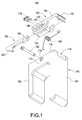
FIG. 1 is an exploded view of a handle structure according to a first embodiment of the present invention. -
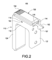
FIG. 2 is a perspective view of the handle structure according to the first embodiment of the present invention. -
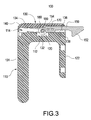
FIG. 3 is a cross-sectional view of the handle structure according to the first embodiment of the present invention. -
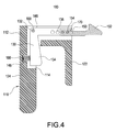
FIG. 4 is a cross-sectional view of the handle structure according to a second embodiment of the present invention. -
FIG. 5 is a cross-sectional view of the handle structure according to a third embodiment of the present invention. -
FIG. 6 is a perspective view of the present invention, illustrating a server using the handle structure. -
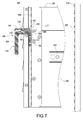
FIG. 7 is a cross-sectional view of the present invention, illustrating the server using the handle structure. -
FIG. 8 is a cross-sectional view of the present invention, illustrating that the handle structure is used to push back the chassis and is engaged with the rack. -
FIG. 9 is a perspective view of the present invention, illustrating that the handle structure is used to push back the chassis and is engaged with the rack. -
FIG. 10 is a cross-sectional view of the present invention, illustrating separating the handle structure from the rack to pull out the chassis. -
FIG. 11 is a cross-sectional view of the present invention, illustrating adjusting a protruding length of a clasp portion of the handle structure. -
FIG. 12 is another cross-sectional view of the present invention, illustrating the server engaged with the rack by means of the handle structure. -
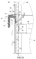
FIG. 13 is a cross-sectional view of the present invention, illustrating separating the handle structure from the rack to pull out the chassis. - Detailed descriptions and technical contents of the present invention are illustrated below in conjunction with the accompany drawings. However, it is to be understood that the descriptions and the accompany drawings disclosed herein are merely illustrative and exemplary and not intended to limit the scope of the present invention.
- Referring to
Figs. 1 to 3 , the present invention provides ahandle structure 100 which includes aholding member 110, apress member 130, and ahook 150. Theholding member 110 includes aholding portion 112 and aspace 114 formed in theholding portion 112. Thepress member 130 includes apress portion 134 and a plurality ofadjustment holes 136, thepress portion 134 is movably disposed in thespace 114, wherein each of theadjustment holes 136 is disposed on the other end of thepress member 130 opposite to thepress portion 134. Thehook 150 includes aclasp portion 152 and at least onefastening hole 154. Thefastening hole 154 is adjustably positioned corresponding to any of theadjustment holes 136, theclasp portion 152 is movable along with the movement of thepress portion 134, wherein theclasp portion 152 protrudes out of theholding member 110. - In the present embodiment, the
handle structure 100 further includes afirst fastening element 160, asecond fastening element 170, and aresilient element 180. Thefirst fastening element 160 fastens thepress member 130 to theholding member 110. Thesecond fastening element 170 passes through the at least onefastening hole 154 and a corresponding one of theadjustment holes 136 to fix thehook 150 to thepress member 130. Theclasp portion 152 of thehook 150 tilts upwards upon pressing thepress portion 134. Thefirst fastening element 160 and thesecond fastening element 170 are screws, bolts, or pins; the present invention is not limited thereto. - The
holding portion 110 further includes twoopposite side walls 116 and twoassembly holes 118 respectively formed on theside walls 116, wherein thespace 114 is formed between the twoside walls 116. Thepress member 130 includes apivot portion 132, and thepivot portion 132 of thepress member 130 includes apivot hole 142 corresponding to theassembly hole 118, so thefirst fastening element 160 passes through theassembly hole 118 and thepivot hole 142 to fasten thepress member 130 to theholding member 110. - Referring to
Fig. 3 , theholding member 110 further includes arecess 120, a securingportion 122 and agrip portion 124. Therecess 120 is formed in theholding portion 112 and communicates with thespace 114, so as to allow thepivot portion 132 to be rotatably accommodated in therecess 120. Referring toFig. 1 , thesecuring portion 122 and thegrip portion 124 are vertically connected to two ends of theholding portion 112. Thegrip portion 124 allows a user to exert force easily. Furthermore, thepress member 130 further includes acontact block 138, thecontact block 138 is accommodated in thespace 114 and abuts theholding portion 112, one end of thecontact block 138 is connected to thepivot portion 132, and each of theadjustment holes 136 is formed on thecontact block 138. In order to facilitate operation by the user, a surface of thepress portion 134 includes a plurality ofknurling portions 140. - It should be noted that the
press member 130 preferably includes a pair ofpivot portions 132 and a pair of contact blocks 138. The twopivot portions 132 are respectively disposed at two sides of thepress member 130, and the twocontact blocks 138 are respectively disposed at two sides of thepress member 130 to enhance the operation stability of thepress portion 134. However, in the present embodiment, only onepivot portion 132 and only onecontact block 138 are described as an example. - Furthermore, the
resilient element 180 is disposed between the holdingmember 110 and thepress member 130 so as to restore thepress portion 134 to an original position thereof. When pressing thepress portion 134, thepress portion 134 rotates about thepivot portion 132 as a center and moves downward toward the inside of thespace 114. At this point, theclasp portion 152 of thehook 150 tilts upward along with the other end (the adjustment hole 136) of thepress member 130 by means of the lever principle. When the user releases thepress portion 134, theresilient element 180 resiliently pushes thepress portion 134 to restore it to its original position. At this point, along with the movement of thepress portion 134, theclasp portion 152 of thehook 150 is also restored to its original position to be parallel to thepress portion 134. - In the present embodiment, the
resilient element 180 is preferably a torsion spring. The torsion spring has two flexible arms (not labeled) respectively contact thepress portion 134 and the holdingportion 112. Since the torsion spring is a conventional technique, descriptions thereof are omitted for brevity. However, in other different embodiment, theresilient element 180 can also be a compression spring (not illustrated), connected to thepress portion 134 and the holdingportion 112, or other suitable flexible elements; the present invention is not limited thereto. Moreover, theclasp portion 152 includes aninclined surface 156 at one side to facilitate engagement with a corresponding retaining hole (not illustrated). - Please refer to
Fig. 4 which is a cross-sectional view according to a second embodiment of the present invention. As shown inFig. 4 , thepress portion 134 is preferably disposed between the securingportion 122 and the holdingportion 112 or between the securingportion 122 and thegrip portion 124, one end of theresilient element 180 is connected to thepress portion 134, and the other end of theresilient element 180 is in contact with arecess 148 of the holdingportion 112. In the present embodiment, thepress member 130 is preferably an L-shaped structure. The L-shaped structure includes apivot portion 132, thepivot portion 132 is disposed close to abend portion 146 of the L-shaped structure, and thefirst fastening element 160 passes through thepivot portion 132 to fix thepress member 130 to the holdingportion 112. - Referring to
Fig. 5 which is a cross-sectional view according to a third embodiment of the present invention, thehandle structure 100 further includes aconnection member 260. Theconnection member 260 includes afirst end 262 and asecond end 264, the holdingmember 110 is connected to thefirst end 262, the at least onefastening hole 154 of thehook 150 is positioned corresponding to thesecond end 264, wherein each of the adjustment holes 136 is formed atsecond end 264. According to the present embodiment, theconnection member 260 is preferably an L-shaped structure which includes apivot portion 132 disposed between thefirst end 262 and thesecond end 264. Thefirst fastening element 160 passes through thepivot portion 132 to fix theconnection member 260 to the holdingportion 112. - In the embodiments of
Figs. 4 and5 , theresilient element 180 is preferably a compression spring. When pushing thepress portion 134, thepress member 130 rotates about thepivot portion 132 as center, thereby directly driving theclasp portion 152 to move or indirectly driving theclasp portion 152 to move downward or upward via theconnection member 260. When thepress portion 134 is released, theresilient element 180 resiliently pushes thepress portion 134 to restore thepress portion 134 to its original position, and thehook 150 also returns to its original position. - It should be noted that, the
press member 130 or theconnection member 260 includes fouradjustment holes 136; the number can vary according to requirement, and the present invention is not limited to any particular number of the adjustment holes 136. Thefastening hole 154 of thehook 150 can be fixed to a corresponding one of the adjustment holes 136 by means of thesecond fastening element 170, so that theclasp portion 152 protrudes from the holdingmember 110 by an adjustable length. - Referring to
Figs. 6 to 9 , the present invention further provides aserver 200 suitable for use in arack 210 having a plurality of retainingholes 220. In the present embodiment, theserver 200 includes achassis 230 and thehandle structure 100 of the foregoing embodiments. Thechassis 230 is slidably connected to therack 210, thechassis 230 includes twoslide rails 240 corresponding to each other, and the twoslide rails 240 are disposed at twoside surfaces 232 of thechassis 230. Thehandle structure 100 is fixed to thechassis 230 and is engaged with a corresponding one of the retainingholes 220 of therack 210. - As shown in the drawings, the
server 200 of the present embodiment further includes a securingplate 250; the securingplate 250 is disposed on one of the side surfaces 232 of thechassis 230, wherein thehandle structure 100 is fixed to thechassis 230 by means of the securingplate 250. The securingplate 250 further includes aplate hole 252 corresponding to the retaininghole 220, theclasp portion 152 is inserted through and extends out of theplate hole 252 to be engaged with the retaininghole 220. - Referring to
Figs. 8 and9 , in the present embodiment, theserver 200 further includes at least onethird fastening element 190, thethird fastening element 190 passes through the securingplate 250 to fix the securingportion 122. Thethird fastening element 190 is a screw, a bolt, or a pin. - Referring to
Fig. 10 , when pressing thepress portion 134, theclasp portion 152 tilts upward along with thepress member 130 to be separated from the retaininghole 220 of therack 210. At this point, the user can exert a force on thegrip portion 124 of the holdingmember 110 to pull out thechassis 230 from therack 210. On the contrary, when the user pushes thechassis 230 back to therack 210, aninclined surface 156 of theclasp portion 152 at one side is resiliently engaged with acorresponding retaining hole 220 to accomplish engagement with therack 210. - Referring to
Figs. 11 to 13 , due to the arrangement of theslide rail 240, different specifications of therack 210, or other reasons, a distance between thechassis 230 and the retaininghole 220 of therack 210 is different. Therefore, a protruding length of theclasp portion 152 has to be adjusted properly. As shown in the drawings, the user can easily detach thesecond fastening element 170 to adjust thehook 150 to be fastened to anappropriate adjustment hole 136, so that theclasp portion 152 protrudes from the holdingmember 110 by a length longer than that in the foregoing embodiments. - Referring to
Figs. 12 and13 , theclasp portion 152 can be engaged with acorresponding retaining hole 220 of therack 210, so as to limit relative movement between thechassis 230 and therack 210. The operation details are described in the foregoing embodiments, so the description thereof is omitted herein for brevity.
Claims (15)
- A handle structure (100), comprising:a holding member (110) including a holding portion (112) and a space (114) formed in the holding portion (112);a press member (130) including a press portion (134) and a plurality of adjustment holes (136), the press portion (134) being movably disposed in the space (114), wherein each of the adjustment holes (136) is disposed on an end of the press member (130) opposite to the press portion (134); anda hook (150) including a clasp portion (152) and at least one fastening hole (154), the at least one fastening hole (154) being adjustably positioned corresponding to any of the adjustment holes (136), the clasp portion (152) being movable along with the movement of the press portion (134), wherein the clasp portion (152) protrudes out of the holding member (110).
- The handle structure of claim 1, further comprising a first fastening element (160), a second fastening element (170), and a resilient element (180), the first fastening element (160) fastening the press member (130) to the holding member (110), the second fastening element (170) passing through the at least one fastening hole (154) to be positioned in a corresponding one of the adjustment holes (136), the resilient element (180) being disposed between the holding member (110) and the press member (130).
- The handle structure of claim 2, wherein the holding portion (112) further includes two opposite side walls (116) and two assembly holes (118) respectively formed on the side walls (116), the press member (130) includes a pivot portion (132), the pivot portion (132) includes a pivot hole (142) corresponding to the assembly hole (118), the first fastening element (160) passes through the assembly hole (118) and the pivot hole (142) to fasten the press member (130), and the space (114) is formed between the two side walls (116).
- The handle structure of claim 3, wherein the press member (130) further includes a contact block (138), the contact block (138) is disposed in the space (114), one end of the contact block (138) is connected to the pivot portion (132), and each of the adjustment holes (136) is formed on the contact block (138).
- The handle structure of claim 3, wherein the holding portion (112) further includes a recess (120), the pivot portion (132) is pivotally connected to the assembly hole (118) of the holding portion (112), and the recess (120) communicates with the space (114).
- The handle structure of claim 2, wherein the holding member (110) further includes a securing portion (122) and a grip portion (124), and the securing portion (122) and the grip portion (124) are connected to two ends of the holding portion (112) respectively.
- The handle structure of claim 2, wherein the press portion (134) is disposed between the securing portion (122) and the holding portion (112), one end of the resilient element (180) is connected to the press portion (134), and the other end of the resilient element (180) is in contact with a recess (148) of the holding portion (112).
- The handle structure of claim 7, wherein the press member (130) is an L-shaped structure, the L-shaped structure includes a pivot portion (132), the pivot portion (132) is disposed close to a bend portion (146) of the L-shaped structure, and the first fastening element (160) passes through the pivot portion (132) to fix the press member (130) to the holding portion (112).
- The handle structure of claim 2, further comprising a connection member (260), the connection member (260) including a first end (262) and a second end (264), the holding member (110) being connected to the first end (262), the at least one fastening hole (154) of the hook (150) being positioned corresponding to the second end (264), wherein each of the adjustment holes (136) is formed at the second end (264).
- The handle structure of claim 9, wherein the connection member (260) is an L-shaped structure, the L-shaped structure includes a pivot portion (132) disposed between the first end (262) and the second end (264), and the first fastening element (160) passes through the pivot portion (132) to fix the connection member (260) to the holding portion (112).
- A server (200), suitable for use in a rack (210) having a plurality of retaining holes (220), comprising:a chassis (230) slidably connected to the rack (210), the chassis (230) including two slide rails (240) corresponding to each other, the two slide rails (240) are disposed at two side surfaces (232) of the chassis (230) respectively, andthe handle structure (100) of any of Claim 1 to 10, the handle structure (100) is fixed to the chassis (230) and is engaged with a corresponding one of the retaining holes (220).
- The server of claim 11, further comprising a securing plate (250), the securing plate (250) being disposed on one of the side surfaces (232) of the chassis (230), wherein the handle structure (100) is fixed to the chassis (230) by means of the securing plate (250).
- The server of claim 11, wherein the securing plate (250) further includes a plate hole (252) corresponding to the retaining hole (220), the clasp portion (152) is inserted through and extends out of the plate hole (252).
- The server of claim 11, further comprising at least one third fastening element (190), the at least one third fastening element (190) passes through the securing plate (250) to fix the securing portion (122).
- The server of claim 11, wherein the hook (150) is correspondingly engaged with the retaining hole (220) to limit relative movement between the chassis (230) and the rack (210).
Applications Claiming Priority (1)
| Application Number | Priority Date | Filing Date | Title |
|---|---|---|---|
| TW104214685U TWM516291U (en) | 2015-09-10 | 2015-09-10 | Handle structure and server using the same |
Publications (3)
| Publication Number | Publication Date |
|---|---|
| EP3148305A2 true EP3148305A2 (en) | 2017-03-29 |
| EP3148305A3 EP3148305A3 (en) | 2017-04-19 |
| EP3148305B1 EP3148305B1 (en) | 2018-12-05 |
Family
ID=55640248
Family Applications (1)
| Application Number | Title | Priority Date | Filing Date |
|---|---|---|---|
| EP16187616.4A Active EP3148305B1 (en) | 2015-09-10 | 2016-09-07 | Handle structure and server using the same |
Country Status (4)
| Country | Link |
|---|---|
| US (1) | US9795052B2 (en) |
| EP (1) | EP3148305B1 (en) |
| CN (1) | CN205158232U (en) |
| TW (1) | TWM516291U (en) |
Families Citing this family (36)
| Publication number | Priority date | Publication date | Assignee | Title |
|---|---|---|---|---|
| US9410348B1 (en) * | 2014-01-04 | 2016-08-09 | Carlson Pet Products, Inc. | Latch apparatus |
| TWM524045U (en) * | 2016-02-19 | 2016-06-11 | Fivetech Technology Inc | Mobile handle |
| TWI625090B (en) * | 2016-05-30 | 2018-05-21 | 仁寶電腦工業股份有限公司 | Chassis structure |
| US10383250B1 (en) * | 2016-09-06 | 2019-08-13 | Amazon Technologies, Inc. | Rack-mountable shippable network-attached data transfer device |
| US10051758B2 (en) * | 2016-09-08 | 2018-08-14 | Oracle International Corporation | Chassis with low-cost, tool-less fastening mechanisms for rack mount systems |
| US10058006B2 (en) * | 2016-12-07 | 2018-08-21 | Dell Products L.P. | Lever release mechanism for information handling system chassis sled |
| CN206640916U (en) * | 2017-02-09 | 2017-11-14 | 索斯科公司 | Computer rack system and frame attachment arrangement |
| US10264698B2 (en) * | 2017-08-25 | 2019-04-16 | Facebook, Inc. | Systems and methods for mounting assembly pull-handles |
| US10687435B2 (en) | 2017-08-28 | 2020-06-16 | Facebook, Inc. | Apparatus, system, and method for enabling multiple storage-system configurations |
| US10349554B2 (en) | 2017-08-29 | 2019-07-09 | Facebook, Inc. | Apparatus, system, and method for directing air in a storage-system chassis |
| US10736228B2 (en) | 2017-08-31 | 2020-08-04 | Facebook, Inc. | Removeable drive-plane apparatus, system, and method |
| US10372360B2 (en) | 2017-09-01 | 2019-08-06 | Facebook, Inc. | Apparatus, system, and method for reconfigurable media-agnostic storage |
| US10537035B2 (en) | 2017-09-06 | 2020-01-14 | Facebook, Inc. | Apparatus, system, and method for securing hard drives in a storage chassis |
| US10429911B2 (en) | 2017-09-07 | 2019-10-01 | Facebook, Inc. | Apparatus, system, and method for detecting device types of storage devices |
| US10558248B2 (en) | 2017-09-09 | 2020-02-11 | Facebook, Inc. | Apparatus, system, and method for indicating the status of and securing hard drives |
| US10588238B2 (en) | 2017-09-18 | 2020-03-10 | Facebook, Inc. | Apparatus, system, and method for partitioning a storage-system chassis |
| US10178791B1 (en) | 2017-09-23 | 2019-01-08 | Facebook, Inc. | Apparatus, system, and method for securing computing components to printed circuit boards |
| US10240615B1 (en) | 2017-09-23 | 2019-03-26 | Facebook, Inc. | Apparatus, system, and method for dampening vibrations generated by exhaust fans |
| US10757831B2 (en) | 2017-09-26 | 2020-08-25 | Facebook, Inc. | Apparatus, system, and method for reconfiguring air flow through a chassis |
| US11549284B2 (en) * | 2018-05-16 | 2023-01-10 | Getac Technology Corporation | Locking structure |
| CN208523095U (en) * | 2018-06-12 | 2019-02-19 | 智邦科技股份有限公司 | Handle, pluggable module and electronic equipment |
| CN109322885B (en) * | 2018-11-05 | 2024-04-02 | 深德彩科技(深圳)股份有限公司 | Locking mechanism and LED display |
| SG11202104001YA (en) * | 2018-12-20 | 2021-05-28 | Canrig Robotic Technologies As | Ex certified robotic system with enhanced corrosion resistance |
| CN109951986B (en) * | 2019-03-27 | 2021-06-29 | 苏州浪潮智能科技有限公司 | a server |
| US10834842B1 (en) * | 2019-06-21 | 2020-11-10 | International Business Machines Corporation | Rack-mountable assembly with spring-hinged mounting bracket(s) |
| TWI709465B (en) * | 2019-11-19 | 2020-11-11 | 和碩聯合科技股份有限公司 | Handle extension structure and electronic device casing |
| US11169581B1 (en) * | 2020-05-28 | 2021-11-09 | EMC IP Holding Company LLC | Cover interlock mechanism |
| TWI732590B (en) | 2020-06-10 | 2021-07-01 | 和碩聯合科技股份有限公司 | Quick releasing device |
| CN216412032U (en) * | 2021-09-03 | 2022-04-29 | 富联精密电子(天津)有限公司 | Hanger assembly and terminal equipment |
| TWI840938B (en) * | 2022-09-02 | 2024-05-01 | 恒昌行精密工業有限公司 | Chassis quick release device |
| US12326167B2 (en) * | 2022-09-02 | 2025-06-10 | Hanwit Precision Industries Ltd. | Chassis quick release device |
| CN115929751B (en) * | 2022-09-30 | 2025-03-25 | 苏州浪潮智能科技有限公司 | Chassis lock and chassis |
| US12408288B2 (en) * | 2023-10-18 | 2025-09-02 | Hewlett Packard Enterprise Development Lp | Riser cage half turn fastener |
| US12408285B2 (en) | 2023-10-27 | 2025-09-02 | Dell Products L.P. | Latch assemblies for protecting chassis |
| US12376246B2 (en) * | 2023-10-27 | 2025-07-29 | Dell Products L.P. | Latch assemblies for data processing systems |
| CN117697369B (en) * | 2024-02-02 | 2024-04-23 | 深圳市德富莱智能科技股份有限公司 | Automatic unlocking system |
Family Cites Families (19)
| Publication number | Priority date | Publication date | Assignee | Title |
|---|---|---|---|---|
| CH611480A5 (en) * | 1977-03-29 | 1979-05-31 | Hasler Ag | Detachable locking device on a plug-in electronic assembly |
| US6185106B1 (en) * | 1995-12-20 | 2001-02-06 | Cisco Technology, Inc. | Printed circuit board extractor tool operated latch |
| US5820175A (en) * | 1996-09-23 | 1998-10-13 | Hartwell Corporation | Self-closing latch |
| US6181549B1 (en) * | 1997-06-24 | 2001-01-30 | Dell Products, L.P. | Chassis retaining system for an electronics rack |
| US6203075B1 (en) * | 1998-05-22 | 2001-03-20 | Hardigg Industries, Inc. | Front opening container latch |
| US6547289B1 (en) * | 1999-11-17 | 2003-04-15 | C-Tech Trailer Cabinets | Quick release latch mechanism |
| US6257439B1 (en) * | 1999-12-01 | 2001-07-10 | Te Hui Hsu | Handle for a food container |
| US6398041B1 (en) * | 1999-12-03 | 2002-06-04 | Hewlett-Packard Company | Snap system for retaining slide mounted rack system into multiple racks without tools |
| EP1392942A4 (en) * | 2001-06-01 | 2008-11-12 | Southco | Latch with bail-type mounting |
| US7125272B1 (en) * | 2005-12-29 | 2006-10-24 | Super Micro Computer, Inc. | Modular case handle positioning device |
| US7633760B2 (en) * | 2007-05-18 | 2009-12-15 | Aten International Co., Ltd | KVM switching device, sever rack assembly and sliding mechanism thereof |
| US7944691B1 (en) * | 2009-08-24 | 2011-05-17 | Astek Corporation | Shock and vibration proof locking handle and pawl assembly |
| CN102236387A (en) * | 2010-04-27 | 2011-11-09 | 鸿富锦精密工业(深圳)有限公司 | Rack server |
| US8608261B2 (en) * | 2010-06-22 | 2013-12-17 | Quality Craft Industries Inc. | Drawer latch |
| US8727138B2 (en) * | 2011-11-04 | 2014-05-20 | International Business Machines Corporation | Toolless rail enabling simplified installation and removal |
| CN103313569A (en) * | 2012-03-15 | 2013-09-18 | 鸿富锦精密工业(深圳)有限公司 | Bracket fixing module |
| US9585283B2 (en) * | 2012-12-27 | 2017-02-28 | Cisco Technology, Inc. | High insertion force ejector |
| US20150250312A1 (en) * | 2014-03-05 | 2015-09-10 | Advantage Pharmacy Services Llc | Pivotable Spring-Loadable Product |
| US9725933B2 (en) * | 2014-11-25 | 2017-08-08 | Super Micro Computer Inc. | Handle structure and server using the same |
-
2015
- 2015-09-10 TW TW104214685U patent/TWM516291U/en not_active IP Right Cessation
- 2015-09-18 CN CN201520727144.7U patent/CN205158232U/en not_active Expired - Lifetime
-
2016
- 2016-01-11 US US14/992,192 patent/US9795052B2/en active Active
- 2016-09-07 EP EP16187616.4A patent/EP3148305B1/en active Active
Non-Patent Citations (1)
| Title |
|---|
| None |
Also Published As
| Publication number | Publication date |
|---|---|
| EP3148305A3 (en) | 2017-04-19 |
| EP3148305B1 (en) | 2018-12-05 |
| US9795052B2 (en) | 2017-10-17 |
| TWM516291U (en) | 2016-01-21 |
| US20170079156A1 (en) | 2017-03-16 |
| CN205158232U (en) | 2016-04-13 |
Similar Documents
| Publication | Publication Date | Title |
|---|---|---|
| EP3148305B1 (en) | Handle structure and server using the same | |
| CN108075328B (en) | Quick buckle structure | |
| US7661778B2 (en) | Fast mounting mechanism for a telescoping slide | |
| CN100582998C (en) | Expansion card fixing structure | |
| US20140133080A1 (en) | Detachable electronic device and connection apparatus usable with the same | |
| CN101470486B (en) | Locking device of extension card | |
| US8366217B1 (en) | Installation device for slide assembly | |
| CN101606789A (en) | Device for fixing slide rail | |
| TW201605322A (en) | Fixing mechanism and electronic device capable of assembling and disassembling an expansion card module | |
| US8869994B2 (en) | Server rack with lockable tray | |
| US8576558B2 (en) | Mounting apparatus with rotating member for retaining and buffering data storage device | |
| US10111354B2 (en) | Storage carrier | |
| US20040190228A1 (en) | Retention device for expansion cards | |
| US20110042985A1 (en) | Extracting apparatus for storage device module | |
| US9261904B2 (en) | Point of sale system | |
| CN102434765B (en) | Height of display adjusting means | |
| US20140153166A1 (en) | Electronic apparatus and detachable assembly thereof | |
| US9510477B1 (en) | Server | |
| US7778017B2 (en) | Clamp-type hard disk mount | |
| US9060426B2 (en) | Securing mechanism | |
| EP2612572B1 (en) | Installation device for slide assembly | |
| US8693182B2 (en) | Fixing mechanism for storage device | |
| CN111459238A (en) | Cabinet | |
| CN104776294A (en) | Displayer lifting device | |
| US7540574B2 (en) | Mounting apparatus for data storage device |
Legal Events
| Date | Code | Title | Description |
|---|---|---|---|
| PUAI | Public reference made under article 153(3) epc to a published international application that has entered the european phase |
Free format text: ORIGINAL CODE: 0009012 |
|
| STAA | Information on the status of an ep patent application or granted ep patent |
Free format text: STATUS: THE APPLICATION HAS BEEN PUBLISHED |
|
| PUAL | Search report despatched |
Free format text: ORIGINAL CODE: 0009013 |
|
| AK | Designated contracting states |
Kind code of ref document: A2 Designated state(s): AL AT BE BG CH CY CZ DE DK EE ES FI FR GB GR HR HU IE IS IT LI LT LU LV MC MK MT NL NO PL PT RO RS SE SI SK SM TR |
|
| AX | Request for extension of the european patent |
Extension state: BA ME |
|
| AK | Designated contracting states |
Kind code of ref document: A3 Designated state(s): AL AT BE BG CH CY CZ DE DK EE ES FI FR GB GR HR HU IE IS IT LI LT LU LV MC MK MT NL NO PL PT RO RS SE SI SK SM TR |
|
| AX | Request for extension of the european patent |
Extension state: BA ME |
|
| RIC1 | Information provided on ipc code assigned before grant |
Ipc: H05K 7/14 20060101AFI20170311BHEP |
|
| STAA | Information on the status of an ep patent application or granted ep patent |
Free format text: STATUS: REQUEST FOR EXAMINATION WAS MADE |
|
| 17P | Request for examination filed |
Effective date: 20171019 |
|
| RBV | Designated contracting states (corrected) |
Designated state(s): AL AT BE BG CH CY CZ DE DK EE ES FI FR GB GR HR HU IE IS IT LI LT LU LV MC MK MT NL NO PL PT RO RS SE SI SK SM TR |
|
| REG | Reference to a national code |
Ref country code: DE Ref legal event code: R079 Ref document number: 602016007779 Country of ref document: DE Free format text: PREVIOUS MAIN CLASS: H05K0007140000 Ipc: H05K0005020000 |
|
| RIC1 | Information provided on ipc code assigned before grant |
Ipc: H05K 5/02 20060101AFI20180522BHEP Ipc: H05K 7/14 20060101ALI20180522BHEP Ipc: H05K 7/18 20060101ALI20180522BHEP |
|
| GRAP | Despatch of communication of intention to grant a patent |
Free format text: ORIGINAL CODE: EPIDOSNIGR1 |
|
| STAA | Information on the status of an ep patent application or granted ep patent |
Free format text: STATUS: GRANT OF PATENT IS INTENDED |
|
| INTG | Intention to grant announced |
Effective date: 20180704 |
|
| GRAS | Grant fee paid |
Free format text: ORIGINAL CODE: EPIDOSNIGR3 |
|
| GRAA | (expected) grant |
Free format text: ORIGINAL CODE: 0009210 |
|
| STAA | Information on the status of an ep patent application or granted ep patent |
Free format text: STATUS: THE PATENT HAS BEEN GRANTED |
|
| AK | Designated contracting states |
Kind code of ref document: B1 Designated state(s): AL AT BE BG CH CY CZ DE DK EE ES FI FR GB GR HR HU IE IS IT LI LT LU LV MC MK MT NL NO PL PT RO RS SE SI SK SM TR |
|
| REG | Reference to a national code |
Ref country code: GB Ref legal event code: FG4D |
|
| REG | Reference to a national code |
Ref country code: CH Ref legal event code: EP |
|
| REG | Reference to a national code |
Ref country code: AT Ref legal event code: REF Ref document number: 1074752 Country of ref document: AT Kind code of ref document: T Effective date: 20181215 |
|
| REG | Reference to a national code |
Ref country code: IE Ref legal event code: FG4D |
|
| REG | Reference to a national code |
Ref country code: DE Ref legal event code: R096 Ref document number: 602016007779 Country of ref document: DE |
|
| REG | Reference to a national code |
Ref country code: NL Ref legal event code: MP Effective date: 20181205 |
|
| REG | Reference to a national code |
Ref country code: AT Ref legal event code: MK05 Ref document number: 1074752 Country of ref document: AT Kind code of ref document: T Effective date: 20181205 |
|
| REG | Reference to a national code |
Ref country code: LT Ref legal event code: MG4D |
|
| PG25 | Lapsed in a contracting state [announced via postgrant information from national office to epo] |
Ref country code: ES Free format text: LAPSE BECAUSE OF FAILURE TO SUBMIT A TRANSLATION OF THE DESCRIPTION OR TO PAY THE FEE WITHIN THE PRESCRIBED TIME-LIMIT Effective date: 20181205 Ref country code: AT Free format text: LAPSE BECAUSE OF FAILURE TO SUBMIT A TRANSLATION OF THE DESCRIPTION OR TO PAY THE FEE WITHIN THE PRESCRIBED TIME-LIMIT Effective date: 20181205 Ref country code: HR Free format text: LAPSE BECAUSE OF FAILURE TO SUBMIT A TRANSLATION OF THE DESCRIPTION OR TO PAY THE FEE WITHIN THE PRESCRIBED TIME-LIMIT Effective date: 20181205 Ref country code: NO Free format text: LAPSE BECAUSE OF FAILURE TO SUBMIT A TRANSLATION OF THE DESCRIPTION OR TO PAY THE FEE WITHIN THE PRESCRIBED TIME-LIMIT Effective date: 20190305 Ref country code: BG Free format text: LAPSE BECAUSE OF FAILURE TO SUBMIT A TRANSLATION OF THE DESCRIPTION OR TO PAY THE FEE WITHIN THE PRESCRIBED TIME-LIMIT Effective date: 20190305 Ref country code: FI Free format text: LAPSE BECAUSE OF FAILURE TO SUBMIT A TRANSLATION OF THE DESCRIPTION OR TO PAY THE FEE WITHIN THE PRESCRIBED TIME-LIMIT Effective date: 20181205 Ref country code: LT Free format text: LAPSE BECAUSE OF FAILURE TO SUBMIT A TRANSLATION OF THE DESCRIPTION OR TO PAY THE FEE WITHIN THE PRESCRIBED TIME-LIMIT Effective date: 20181205 Ref country code: LV Free format text: LAPSE BECAUSE OF FAILURE TO SUBMIT A TRANSLATION OF THE DESCRIPTION OR TO PAY THE FEE WITHIN THE PRESCRIBED TIME-LIMIT Effective date: 20181205 |
|
| PG25 | Lapsed in a contracting state [announced via postgrant information from national office to epo] |
Ref country code: AL Free format text: LAPSE BECAUSE OF FAILURE TO SUBMIT A TRANSLATION OF THE DESCRIPTION OR TO PAY THE FEE WITHIN THE PRESCRIBED TIME-LIMIT Effective date: 20181205 Ref country code: SE Free format text: LAPSE BECAUSE OF FAILURE TO SUBMIT A TRANSLATION OF THE DESCRIPTION OR TO PAY THE FEE WITHIN THE PRESCRIBED TIME-LIMIT Effective date: 20181205 Ref country code: RS Free format text: LAPSE BECAUSE OF FAILURE TO SUBMIT A TRANSLATION OF THE DESCRIPTION OR TO PAY THE FEE WITHIN THE PRESCRIBED TIME-LIMIT Effective date: 20181205 Ref country code: GR Free format text: LAPSE BECAUSE OF FAILURE TO SUBMIT A TRANSLATION OF THE DESCRIPTION OR TO PAY THE FEE WITHIN THE PRESCRIBED TIME-LIMIT Effective date: 20190306 |
|
| PG25 | Lapsed in a contracting state [announced via postgrant information from national office to epo] |
Ref country code: NL Free format text: LAPSE BECAUSE OF FAILURE TO SUBMIT A TRANSLATION OF THE DESCRIPTION OR TO PAY THE FEE WITHIN THE PRESCRIBED TIME-LIMIT Effective date: 20181205 |
|
| PG25 | Lapsed in a contracting state [announced via postgrant information from national office to epo] |
Ref country code: PT Free format text: LAPSE BECAUSE OF FAILURE TO SUBMIT A TRANSLATION OF THE DESCRIPTION OR TO PAY THE FEE WITHIN THE PRESCRIBED TIME-LIMIT Effective date: 20190405 Ref country code: CZ Free format text: LAPSE BECAUSE OF FAILURE TO SUBMIT A TRANSLATION OF THE DESCRIPTION OR TO PAY THE FEE WITHIN THE PRESCRIBED TIME-LIMIT Effective date: 20181205 Ref country code: PL Free format text: LAPSE BECAUSE OF FAILURE TO SUBMIT A TRANSLATION OF THE DESCRIPTION OR TO PAY THE FEE WITHIN THE PRESCRIBED TIME-LIMIT Effective date: 20181205 Ref country code: IT Free format text: LAPSE BECAUSE OF FAILURE TO SUBMIT A TRANSLATION OF THE DESCRIPTION OR TO PAY THE FEE WITHIN THE PRESCRIBED TIME-LIMIT Effective date: 20181205 |
|
| PG25 | Lapsed in a contracting state [announced via postgrant information from national office to epo] |
Ref country code: EE Free format text: LAPSE BECAUSE OF FAILURE TO SUBMIT A TRANSLATION OF THE DESCRIPTION OR TO PAY THE FEE WITHIN THE PRESCRIBED TIME-LIMIT Effective date: 20181205 Ref country code: SM Free format text: LAPSE BECAUSE OF FAILURE TO SUBMIT A TRANSLATION OF THE DESCRIPTION OR TO PAY THE FEE WITHIN THE PRESCRIBED TIME-LIMIT Effective date: 20181205 Ref country code: RO Free format text: LAPSE BECAUSE OF FAILURE TO SUBMIT A TRANSLATION OF THE DESCRIPTION OR TO PAY THE FEE WITHIN THE PRESCRIBED TIME-LIMIT Effective date: 20181205 Ref country code: IS Free format text: LAPSE BECAUSE OF FAILURE TO SUBMIT A TRANSLATION OF THE DESCRIPTION OR TO PAY THE FEE WITHIN THE PRESCRIBED TIME-LIMIT Effective date: 20190405 Ref country code: SK Free format text: LAPSE BECAUSE OF FAILURE TO SUBMIT A TRANSLATION OF THE DESCRIPTION OR TO PAY THE FEE WITHIN THE PRESCRIBED TIME-LIMIT Effective date: 20181205 |
|
| REG | Reference to a national code |
Ref country code: DE Ref legal event code: R097 Ref document number: 602016007779 Country of ref document: DE |
|
| PLBE | No opposition filed within time limit |
Free format text: ORIGINAL CODE: 0009261 |
|
| STAA | Information on the status of an ep patent application or granted ep patent |
Free format text: STATUS: NO OPPOSITION FILED WITHIN TIME LIMIT |
|
| PG25 | Lapsed in a contracting state [announced via postgrant information from national office to epo] |
Ref country code: DK Free format text: LAPSE BECAUSE OF FAILURE TO SUBMIT A TRANSLATION OF THE DESCRIPTION OR TO PAY THE FEE WITHIN THE PRESCRIBED TIME-LIMIT Effective date: 20181205 Ref country code: SI Free format text: LAPSE BECAUSE OF FAILURE TO SUBMIT A TRANSLATION OF THE DESCRIPTION OR TO PAY THE FEE WITHIN THE PRESCRIBED TIME-LIMIT Effective date: 20181205 |
|
| 26N | No opposition filed |
Effective date: 20190906 |
|
| PG25 | Lapsed in a contracting state [announced via postgrant information from national office to epo] |
Ref country code: TR Free format text: LAPSE BECAUSE OF FAILURE TO SUBMIT A TRANSLATION OF THE DESCRIPTION OR TO PAY THE FEE WITHIN THE PRESCRIBED TIME-LIMIT Effective date: 20181205 |
|
| PG25 | Lapsed in a contracting state [announced via postgrant information from national office to epo] |
Ref country code: MC Free format text: LAPSE BECAUSE OF FAILURE TO SUBMIT A TRANSLATION OF THE DESCRIPTION OR TO PAY THE FEE WITHIN THE PRESCRIBED TIME-LIMIT Effective date: 20181205 |
|
| REG | Reference to a national code |
Ref country code: CH Ref legal event code: PL |
|
| PG25 | Lapsed in a contracting state [announced via postgrant information from national office to epo] |
Ref country code: LI Free format text: LAPSE BECAUSE OF NON-PAYMENT OF DUE FEES Effective date: 20190930 Ref country code: CH Free format text: LAPSE BECAUSE OF NON-PAYMENT OF DUE FEES Effective date: 20190930 Ref country code: IE Free format text: LAPSE BECAUSE OF NON-PAYMENT OF DUE FEES Effective date: 20190907 Ref country code: LU Free format text: LAPSE BECAUSE OF NON-PAYMENT OF DUE FEES Effective date: 20190907 |
|
| REG | Reference to a national code |
Ref country code: BE Ref legal event code: MM Effective date: 20190930 |
|
| PG25 | Lapsed in a contracting state [announced via postgrant information from national office to epo] |
Ref country code: BE Free format text: LAPSE BECAUSE OF NON-PAYMENT OF DUE FEES Effective date: 20190930 |
|
| PG25 | Lapsed in a contracting state [announced via postgrant information from national office to epo] |
Ref country code: CY Free format text: LAPSE BECAUSE OF FAILURE TO SUBMIT A TRANSLATION OF THE DESCRIPTION OR TO PAY THE FEE WITHIN THE PRESCRIBED TIME-LIMIT Effective date: 20181205 |
|
| PG25 | Lapsed in a contracting state [announced via postgrant information from national office to epo] |
Ref country code: MT Free format text: LAPSE BECAUSE OF FAILURE TO SUBMIT A TRANSLATION OF THE DESCRIPTION OR TO PAY THE FEE WITHIN THE PRESCRIBED TIME-LIMIT Effective date: 20181205 Ref country code: HU Free format text: LAPSE BECAUSE OF FAILURE TO SUBMIT A TRANSLATION OF THE DESCRIPTION OR TO PAY THE FEE WITHIN THE PRESCRIBED TIME-LIMIT; INVALID AB INITIO Effective date: 20160907 |
|
| PG25 | Lapsed in a contracting state [announced via postgrant information from national office to epo] |
Ref country code: MK Free format text: LAPSE BECAUSE OF FAILURE TO SUBMIT A TRANSLATION OF THE DESCRIPTION OR TO PAY THE FEE WITHIN THE PRESCRIBED TIME-LIMIT Effective date: 20181205 |
|
| PGFP | Annual fee paid to national office [announced via postgrant information from national office to epo] |
Ref country code: DE Payment date: 20250930 Year of fee payment: 10 |
|
| PGFP | Annual fee paid to national office [announced via postgrant information from national office to epo] |
Ref country code: GB Payment date: 20250804 Year of fee payment: 10 |
|
| PGFP | Annual fee paid to national office [announced via postgrant information from national office to epo] |
Ref country code: FR Payment date: 20250807 Year of fee payment: 10 |