EP3148241B1 - Capacity expansion method and device for wireless network - Google Patents
Capacity expansion method and device for wireless network Download PDFInfo
- Publication number
- EP3148241B1 EP3148241B1 EP14892639.7A EP14892639A EP3148241B1 EP 3148241 B1 EP3148241 B1 EP 3148241B1 EP 14892639 A EP14892639 A EP 14892639A EP 3148241 B1 EP3148241 B1 EP 3148241B1
- Authority
- EP
- European Patent Office
- Prior art keywords
- grids
- base station
- grid
- network
- deployed
- Prior art date
- Legal status (The legal status is an assumption and is not a legal conclusion. Google has not performed a legal analysis and makes no representation as to the accuracy of the status listed.)
- Active
Links
Images



Classifications
-
- H—ELECTRICITY
- H04—ELECTRIC COMMUNICATION TECHNIQUE
- H04W—WIRELESS COMMUNICATION NETWORKS
- H04W16/00—Network planning, e.g. coverage or traffic planning tools; Network deployment, e.g. resource partitioning or cells structures
- H04W16/22—Traffic simulation tools or models
-
- H—ELECTRICITY
- H04—ELECTRIC COMMUNICATION TECHNIQUE
- H04W—WIRELESS COMMUNICATION NETWORKS
- H04W16/00—Network planning, e.g. coverage or traffic planning tools; Network deployment, e.g. resource partitioning or cells structures
- H04W16/18—Network planning tools
-
- H—ELECTRICITY
- H04—ELECTRIC COMMUNICATION TECHNIQUE
- H04W—WIRELESS COMMUNICATION NETWORKS
- H04W16/00—Network planning, e.g. coverage or traffic planning tools; Network deployment, e.g. resource partitioning or cells structures
- H04W16/24—Cell structures
- H04W16/32—Hierarchical cell structures
Definitions
- the present invention pertains to the field of wireless communications technologies, and specifically relates to a wireless network capacity expansion method and device.
- a most effective network capacity expansion means is to add and deploy a micro cellular base station or a pico cellular base station (hereinafter referred to as a micro base station) based on an existing macro cellular base station (hereinafter referred to as a macro base station), so as to improve a network capacity by means of better spectrum reuse.
- One important problem during networking of a heterogeneous network is how to deploy and configure a plurality of micro base stations based on an existing macro cellular network to construct a heterogeneous network including a plurality of macro base stations and micro base stations.
- a macro base station is added to the macro cellular network by means of a drive test.
- this method is not applicable to deployment of micro base stations, because a quantity of newly-added micro base stations is much greater than that of macro base stations.
- the drive test method is time-consuming and effort-consuming.
- grid division is performed on a target region, and a grid in which a micro base station is deployed is determined aiming at a minimum average path loss from grids to micro base station covering the grids.
- a device identifies mobile devices within a geographical area associated with a carrier network.
- the device further divides the geographical area into cells.
- the device also collects network statistics associated with the mobile devices.
- the device assigns values to the cells based on the network statistics, and identifies locations in which to place the small cells within the geographical area based on the values.
- the present invention provides a wireless network capacity expansion method and device, so as to overcome a disadvantage in the prior art that it is difficult to ensure a network capacity after a micro base station is added.
- grid division is performed on a target region covered by a macro cellular network, to obtain a plurality of grids, and N first grids are determined among the plurality of grids based on a network gain, where the N first grids need to meet a condition: deploying one micro base station in each of the first grids brings a maximum network gain corresponding to the target region.
- a position of a grid in which a micro base station is deployed is determined based on the network gain, which optimizes a network capacity to a greatest extent when one micro base station is deployed in each grid of the determined N first grids.
- FIG. 1 is a flowchart of a wireless network capacity expansion method according to Embodiment 1 of the present invention.
- the method provided in this embodiment is particularly applicable to any scenario in which a network capacity is expanded by adding and deploying a micro base station on a wireless communications network, and is particularly applicable to a mobile cellular network.
- Different types of micro base stations may be deployed in different wireless networks.
- a micro base station deployed in the mobile cellular network may be a small cell or an access point.
- the method may be executed by a network side device.
- the device is on a management platform of an operator, or in an operation and maintenance center (Operation and Maintenance Center, OMC for short).
- OMC Opera and Maintenance Center
- grid division is first performed on the target region covered by the macro cellular network, to obtain the plurality of grids.
- the target region covered by the macro cellular network includes a plurality of macro base stations, and each macro base station covers an area, that is, each macro base station covers a plurality of grids.
- At least one group of N first grids needs to be determined among the plurality of grids obtained by means of gridding, for example, M (M is an integer greater than or equal to 1) groups of N first grids. That is, there are totally M groups, and each group includes N first grids.
- M is an integer greater than or equal to 1
- each group includes N first grids.
- Deploying one micro base station in each grid of the M ⁇ N first grids brings a maximum network capacity of the target region. That is, each group of N first grids in this embodiment needs to meet a condition: deploying one micro base station in each first grid brings the maximum network gain corresponding to the target region.
- the network gain may include a network capacity gain and a network coverage gain.
- the network capacity gain represents an optimization degree of the network capacity of the target region
- the network coverage gain represents an optimization degree of network coverage of the target region, that is, a degree to which coverage vulnerability is caused by interference caused by a newly-added micro base station to a user.
- a greater network coverage gain indicates a lower degree to which coverage vulnerability is caused by the interference caused by the newly-added micro base station to the user.
- the network gain is maximum means that the network capacity gain is maximum while a requirement for the network coverage gain is met.
- the N first grids meeting the foregoing condition are determined among the plurality of grids obtained by gridding the target region.
- the N first grids may be determined in the following manner. It is assumed that A grids are obtained by means of gridding, N grids are randomly selected from the A grids each time, and the network gain: the network capacity gain and the network coverage gain, that are brought about if one micro base station is deployed in each of the N randomly selected grids is determined by analogy, until all possibilities of random selection are tried; then, the network gains corresponding to all random selections are compared, N grids corresponding to a random selection with a greatest network gain is determined, and one micro base station is deployed in each of the N grids.
- the foregoing process is repeated for multiple times, so as to finally determine a plurality of groups of N first grids, and micro base stations are deployed in the plurality of groups of N first grids, so as to implement network capacity expansion.
- Optional implementation manners are described in the following other embodiments.
- grid division is performed on a target region covered by a macro cellular network, to obtain a plurality of grids, and based on a network gain including a network capacity gain and a network coverage gain, N first grids are determined among the plurality of grids, where the N first grids need to meet a condition: deploying one micro base station in each of the first grids brings a maximum network gain corresponding to the target region.
- a position of a grid in which a micro base station is deployed is determined based on the network gain, which optimizes a network capacity when a coverage requirement is met.
- FIG. 2 is a flowchart of a wireless network capacity expansion method according to Embodiment 2 of the present invention. As shown in FIG. 2 , the method includes: Step 201: Perform grid division on a target region covered by a macro cellular network, to obtain a plurality of grids.
- N first grids need to be determined among the plurality of grids, which may be specifically implemented by using the following process:
- Step 203 Determine that grids that enable the network capacity gain to be greater than 0 and the network coverage gain to be greater than 0 constitute the L second grids.
- N first grids are determined among the L second grids includes:
- the following condition needs to be met: it is assumed that micro base stations are deployed in any two second grids in the L second grids, interference between the any two grids is less than a preset interference threshold. A distance between grids that meets the condition is defined as the interference distance threshold, and the interference distance threshold is used as a parameter for subsequently selecting and determining the N first grids.
- a process of determining at least one group of N first grids among the L second grids is a multi-iteration process, and each iteration results in one group of N first grids.
- a preset iteration termination condition is met, iteration ends, at least one group of N first grids is finally obtained, and one micro base station is deployed in each of the at least one group of N first grids.
- the iteration termination condition includes: a quantity of iterations reaches a preset quantity of times, or a difference between network gains corresponding to two adjacent groups of N first grids that are obtained by means of iteration is less than a preset difference.
- One traverse specifically includes the following steps:
- the L second grids are first sorted randomly; then, the L second grids are traversed, and the N third grids are selected from the L second grids, where a distance between any two third grids is greater than the interference distance threshold; and whether deploying one micro base station in each of the third grids brings the maximum network gain corresponding to the target region is determined, and if deploying one micro base station in each of the third grids brings the maximum network gain corresponding to the target region, the N third grids are determined as the N first grids.
- L second grids that can be used as candidate grids for deploying micro base stations are determined among a plurality of grids obtained from an original gridded target region, and then, at least one group of N first grids is determined among the L second grids and is used as final grids for deploying the micro base stations, thereby not only further reducing calculation amount, but also ensuring an accurate determining result, which facilitates optimization of a network capacity and network coverage.
- parameters of a newly-added micro base station and an existing macro base station may be adjusted, and a specific adjustment process is as follows:
- each grid of the plurality of grids obtained after the target region is gridded is used as a to-be-processed grid. It is assumed that before a micro base station is deployed, a to-be-processed grid i is associated with a macro base station c, that is, the to-be-processed grid i is covered by the macro base station c , and it can be determined that first reference signal strength RS i of the macro base station c in the to-be-processed grid i is determined by P c g i c .
- the to-be-processed grid i may be no longer associated with the macro base station c, and may be associated with a micro base station c', that is, the to-be-processed grid i is covered by the micro base station c'.
- second reference signal strength RS i of the micro base station c' in the to-be-processed grid i is determined by P c ′ g i c ′ .
- the second reference signal strength is greater than the first reference signal strength, it is considered that the micro base station c' that the to-be-processed grid i is associated with is a to-be-adjusted base station, and a parameter of the to-be-adjusted base station c' needs to be adjusted.
- the second reference signal strength is generally compared with a product of the first reference signal strength and a sensitivity coefficient.
- a to-be-adjusted parameter includes a transmit power and/or an antenna downtilt.
- the transmit power of the to-be-adjusted base station is adjusted according to a first preset step; or the antenna downtilt of the to-be-adjusted base station is adjusted according to a second preset step.
- the foregoing adjustment process is performed time by time, that is, each adjustment is performed according to the preset steps, and after each adjustment, whether a network capacity gain of the target region after each adjustment is greater than 0 needs to be determined, next adjustment is performed if the network capacity gain is greater than 0, and so on, and adjusting the to-be-adjusted base station ends when the network capacity gain is not greater than 0.
- a transmit power range is configured for each to-be-adjusted base station, and adjustment is performed time by time by using the first preset step as a unit within the range.
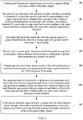
- FIG. 3 is a flowchart of a multi-iteration process in Embodiment 2 shown in FIG. 2 , and as shown in FIG. 3 :
- an iteration termination condition may also be that a network gain difference between two groups of N first grids of two adjacent iteration results is less than a preset threshold.
- Step 315 Obtain at least one group of N first grids.
- FIG. 4 is a schematic structural diagram of a wireless network capacity expansion device according to Embodiment 3 of the present invention. As shown in FIG. 4 , the device includes:
- the device in this embodiment may be configured to execute a technical solution of the method embodiment shown in FIG. 1 , and implementation principles and technical effects thereof are similar, and details are not described herein again.
- FIG. 5 is a schematic structural diagram of a wireless network capacity expansion device according to Embodiment 4 of the present invention. As shown in FIG. 5 , the device in this embodiment is based on the embodiment shown in FIG. 4 , and the processing module 12 includes:
- the first processing unit 121 includes: a first calculation subunit 1211, configured to: successively for each grid of the plurality of grids, calculate, according to formula (1), a network capacity gain that is corresponding to the target region and that is obtained after one micro base station is deployed independently in each grid, and calculate, according to formula (2), a network coverage gain that is corresponding to the target region and that is obtained after one micro base station is deployed in each grid:
- U 1 p Capacity S ⁇ p ⁇ Capacity S
- U 2 p Coverage S ⁇ p ⁇ Coverage S
- U 1 ( p ) is the network capacity gain that is corresponding to the target region and that is obtained after one micro base station is deployed in any grid p in the plurality of grids
- U 2 ( p ) is the network coverage gain that is corresponding to the target region and that is obtained after one micro base station is deployed in any grid p in the plurality of grids
- S is a set of macro base stations included in the target region
- the second processing unit 122 specifically includes:
- the selection subunit 1221 is specifically configured to:
- the device further includes:
- the adjustment module 22 is specifically configured to: adjust a transmit power of the to-be-adjusted base station according to a first preset step; or adjust an antenna downtilt of the to-be-adjusted base station according to a second preset step.
- the device in this embodiment may be configured to execute technical solutions of the method embodiments shown in FIG. 2 and FIG. 3 , and implementation principles and technical effects thereof are similar, and details are not described herein again.
- FIG. 6 is a schematic structural diagram of a network device according to Embodiment 5 of the present invention.
- the network device includes: a memory 31 and a processor 32 connected to the memory 31, where the memory 31 is configured to store a set of program code, and the processor 32 is configured to invoke the program code stored in the memory 31 to execute steps in the wireless network capacity expansion method shown in FIG.
- the processor 32 is further configured to: determine L second grids among the plurality of grids, where deploying one micro base station in each of the second grids increases a network gain corresponding to the target region, and L is an integer greater than N; and determine the N first grids among the L second grids.
- the processor 32 is further configured to: successively for each grid of the plurality of grids, calculate, according to formula (1), a network capacity gain that is corresponding to the target region and that is obtained after one micro base station is deployed independently in each grid, and calculate, according to formula (2), a network coverage gain that is corresponding to the target region and that is obtained after one micro base station is deployed in each grid:
- U 1 p Capacity S ⁇ p ⁇ Capacity S
- U 2 p Coverage S ⁇ p ⁇ Coverage S
- U 1 ( p ) is the network capacity gain that is corresponding to the target region and that is obtained after one micro base station is deployed in any grid p in the plurality of grids
- U 2 ( p ) is the network coverage gain that is corresponding to the target region and that is obtained after one micro base station is deployed in any grid p in the plurality of grids
- S is a set of macro base stations included in the target region
- Capacity ( S ) is a network capacity that is of
- the processor 32 is further configured to traverse the L second grids, and determine N third grids among the L second grids, where a distance between any two third grids is greater than an interference distance threshold; and determine the N third grids as the N first grids if deploying one micro base station in each of the third grids brings the maximum network gain corresponding to the target region.
- the processor 32 is further configured to: by using each grid of the plurality of grids as a to-be-processed grid, determine first reference signal strength that is of the to-be-processed grid and that is obtained before one micro base station is deployed in each of the first grids, and second reference signal strength that is of the to-be-processed grid and that is obtained after one micro base station is deployed in each of the first grids; and if the second reference signal strength is greater than the first reference signal strength, determine a base station corresponding to the to-be-processed grid as a to-be-adjusted base station, and adjust a parameter of the to-be-adjusted base station.
- the processor 32 is further configured to adjust a transmit power of the to-be-adjusted base station according to a first preset step; or adjust an antenna downtilt of the to-be-adjusted base station according to a second preset step.
- the previous program may be stored in a computer readable storage medium. When the program is run, the steps of the foregoing method embodiments are performed.
- the previous storage medium includes various mediums that are capable of storing the program code, such as a ROM, a RAM, a magnetic disk, or an optical disc.
Landscapes
- Engineering & Computer Science (AREA)
- Computer Networks & Wireless Communication (AREA)
- Signal Processing (AREA)
- Mobile Radio Communication Systems (AREA)
Description
- The present invention pertains to the field of wireless communications technologies, and specifically relates to a wireless network capacity expansion method and device.
- As mobile service types keep increasing, there are increasing requirements imposed on a service transmission rate, and a capacity of a wireless network needs to be expanded to meet the ever-increasing requirements. Because available spectrum resources are limited, at present, a most effective network capacity expansion means is to add and deploy a micro cellular base station or a pico cellular base station (hereinafter referred to as a micro base station) based on an existing macro cellular base station (hereinafter referred to as a macro base station), so as to improve a network capacity by means of better spectrum reuse.
- One important problem during networking of a heterogeneous network is how to deploy and configure a plurality of micro base stations based on an existing macro cellular network to construct a heterogeneous network including a plurality of macro base stations and micro base stations. At present, a macro base station is added to the macro cellular network by means of a drive test. However, this method is not applicable to deployment of micro base stations, because a quantity of newly-added micro base stations is much greater than that of macro base stations. The drive test method is time-consuming and effort-consuming. According to an existing micro base station deployment method, grid division is performed on a target region, and a grid in which a micro base station is deployed is determined aiming at a minimum average path loss from grids to micro base station covering the grids.
- The document
US2013/0040648 A1 discloses that a device identifies mobile devices within a geographical area associated with a carrier network. The device further divides the geographical area into cells. The device also collects network statistics associated with the mobile devices. The device assigns values to the cells based on the network statistics, and identifies locations in which to place the small cells within the geographical area based on the values. - However, the foregoing solution of determining the grid in which the micro base station is deployed aiming at the minimum average path loss is very likely to fail to ensure a network capacity after the micro base station is added.
- The present invention provides a wireless network capacity expansion method and device, so as to overcome a disadvantage in the prior art that it is difficult to ensure a network capacity after a micro base station is added.
- Aspects of the invention are set out in the claims.
- According to the wireless network capacity expansion method and device provided in the present invention, grid division is performed on a target region covered by a macro cellular network, to obtain a plurality of grids, and N first grids are determined among the plurality of grids based on a network gain, where the N first grids need to meet a condition: deploying one micro base station in each of the first grids brings a maximum network gain corresponding to the target region. A position of a grid in which a micro base station is deployed is determined based on the network gain, which optimizes a network capacity to a greatest extent when one micro base station is deployed in each grid of the determined N first grids.
-
-
FIG. 1 is a flowchart of a wireless network capacity expansion method according toEmbodiment 1 of the present invention; -
FIG. 2 is a flowchart of a wireless network capacity expansion method according toEmbodiment 2 of the present invention; -
FIG. 3 is a flowchart of a multi-iteration process inEmbodiment 2 shown inFIG. 2 ; -
FIG. 4 is a schematic structural diagram of a wireless network capacity expansion device according to Embodiment 3 of the present invention; -
FIG. 5 is a schematic structural diagram of a wireless network capacity expansion device according to Embodiment 4 of the present invention; and -
FIG. 6 is a schematic structural diagram of a network device according to Embodiment 5 of the present invention. - To make the objectives, technical solutions, and advantages of embodiments of the present invention clearer, the following clearly and completely describes the technical solutions in the embodiments of the present invention with reference to the accompanying drawings in the embodiments of the present invention. Apparently, the described embodiments are a part rather than all of the embodiments of the present invention. All other embodiments obtained by a person of ordinary skill in the art based on the embodiments of the present invention without creative efforts shall fall within the protection scope of the present invention.
-
FIG. 1 is a flowchart of a wireless network capacity expansion method according toEmbodiment 1 of the present invention. As shown inFIG. 1 , the method provided in this embodiment is particularly applicable to any scenario in which a network capacity is expanded by adding and deploying a micro base station on a wireless communications network, and is particularly applicable to a mobile cellular network. Different types of micro base stations may be deployed in different wireless networks. For example, a micro base station deployed in the mobile cellular network may be a small cell or an access point. In addition, the method may be executed by a network side device. For example, the device is on a management platform of an operator, or in an operation and maintenance center (Operation and Maintenance Center, OMC for short). The method specifically includes: - Step 101: Perform grid division on a target region covered by a macro cellular network, to obtain a plurality of grids.
- Step 102: Determine N first grids among the plurality of grids, where deploying one micro base station in each of the first grids brings a maximum network gain corresponding to the target region, and N is an integer greater than 1.
- Step 103: Determine that one micro base station is deployed in each first grid of the N first grids.
- In this embodiment, grid division is first performed on the target region covered by the macro cellular network, to obtain the plurality of grids. It can be understood that the target region covered by the macro cellular network includes a plurality of macro base stations, and each macro base station covers an area, that is, each macro base station covers a plurality of grids.
- To implement network capacity expansion, in a solution provided in this embodiment, while a basic requirement for a network coverage of the target region is met, at least one group of N first grids needs to be determined among the plurality of grids obtained by means of gridding, for example, M (M is an integer greater than or equal to 1) groups of N first grids. That is, there are totally M groups, and each group includes N first grids. Deploying one micro base station in each grid of the M∗N first grids brings a maximum network capacity of the target region. That is, each group of N first grids in this embodiment needs to meet a condition: deploying one micro base station in each first grid brings the maximum network gain corresponding to the target region. The network gain may include a network capacity gain and a network coverage gain. In this embodiment, the network capacity gain represents an optimization degree of the network capacity of the target region, and the network coverage gain represents an optimization degree of network coverage of the target region, that is, a degree to which coverage vulnerability is caused by interference caused by a newly-added micro base station to a user. A greater network coverage gain indicates a lower degree to which coverage vulnerability is caused by the interference caused by the newly-added micro base station to the user. In this embodiment, optionally, the network gain is maximum means that the network capacity gain is maximum while a requirement for the network coverage gain is met.
- The N first grids meeting the foregoing condition are determined among the plurality of grids obtained by gridding the target region. For example, the N first grids may be determined in the following manner. It is assumed that A grids are obtained by means of gridding, N grids are randomly selected from the A grids each time, and the network gain: the network capacity gain and the network coverage gain, that are brought about if one micro base station is deployed in each of the N randomly selected grids is determined by analogy, until all possibilities of random selection are tried; then, the network gains corresponding to all random selections are compared, N grids corresponding to a random selection with a greatest network gain is determined, and one micro base station is deployed in each of the N grids. Optionally, the foregoing process is repeated for multiple times, so as to finally determine a plurality of groups of N first grids, and micro base stations are deployed in the plurality of groups of N first grids, so as to implement network capacity expansion. Optional implementation manners are described in the following other embodiments.
- In this embodiment, grid division is performed on a target region covered by a macro cellular network, to obtain a plurality of grids, and based on a network gain including a network capacity gain and a network coverage gain, N first grids are determined among the plurality of grids, where the N first grids need to meet a condition: deploying one micro base station in each of the first grids brings a maximum network gain corresponding to the target region. A position of a grid in which a micro base station is deployed is determined based on the network gain, which optimizes a network capacity when a coverage requirement is met.
-
FIG. 2 is a flowchart of a wireless network capacity expansion method according toEmbodiment 2 of the present invention. As shown inFIG. 2 , the method includes:
Step 201: Perform grid division on a target region covered by a macro cellular network, to obtain a plurality of grids. - In this embodiment, after the grid division is performed on the target region covered by the macro cellular network and the plurality of grids are obtained, N first grids need to be determined among the plurality of grids, which may be specifically implemented by using the following process:
- determining L second grids among the plurality of grids, where deploying one micro base station in each of the second grids increases a network gain corresponding to the target region, and L is an integer greater than N; and
- determining the N first grids among the L second grids.
- In this embodiment, to reduce a calculation amount and enable an accurate result, the L second grids are first selected from the plurality of grids obtained by means of gridding, and the L second grids need to meet a condition: deploying one micro base station in each of the second grids increases a network gain corresponding to the target region, that is, a network capacity gain and a network coverage gain are increased, which is specifically implemented by using the following steps:
Step 202: Successively for each grid of the plurality of grids, calculate, according to formula (1), a network capacity gain that is corresponding to the target region and that is obtained after one micro base station is deployed independently in each grid, and calculate, according to formula (2), a network coverage gain that is corresponding to the target region and that is obtained after one micro base station is deployed in each grid:


- Step 203: Determine that grids that enable the network capacity gain to be greater than 0 and the network coverage gain to be greater than 0 constitute the L second grids.
- Further, that the N first grids are determined among the L second grids includes:
- Step 204: Traverse the L second grids, and determine N third grids among the L second grids, where a distance between any two third grids is greater than an interference distance threshold.
- Step 205: Determine the N third grids as the N first grids if deploying one micro base station in each of the third grids brings a maximum network gain corresponding to the target region.
- In this embodiment, to ensure that deploying micro base stations in the selected and determined N first grids causes no interference between the micro base stations or between a micro base station and a macro base station, the following condition needs to be met: it is assumed that micro base stations are deployed in any two second grids in the L second grids, interference between the any two grids is less than a preset interference threshold. A distance between grids that meets the condition is defined as the interference distance threshold, and the interference distance threshold is used as a parameter for subsequently selecting and determining the N first grids.
- The interference distance threshold in this embodiment is determined in the following manner: determining interference between any two of the L second grids according to formula (6):

determining a distance between grids that enables the interference to be less than the preset interference threshold as the interference distance threshold. - Specifically, in this embodiment, a process of determining at least one group of N first grids among the L second grids is a multi-iteration process, and each iteration results in one group of N first grids. When a preset iteration termination condition is met, iteration ends, at least one group of N first grids is finally obtained, and one micro base station is deployed in each of the at least one group of N first grids. The iteration termination condition includes: a quantity of iterations reaches a preset quantity of times, or a difference between network gains corresponding to two adjacent groups of N first grids that are obtained by means of iteration is less than a preset difference.
- In this embodiment, only a process of one traverse is used as an example for brief description, and a detailed multi-iteration process is described in detail in an embodiment shown in
FIG. 3 . One traverse specifically includes the following steps: - randomly sort the L second grids;
- traverse the L second grids, and determine the N third grids among the L second grids, where a distance between any two third grids is greater than the interference distance threshold;
- determine whether deploying one micro base station in each of the third grids brings the maximum network gain corresponding to the target region, and if deploying one micro base station in each of the third grids does not bring the maximum network gain corresponding to the target region, execute a next step, or if deploying one micro base station in each of the third grids does not bring the maximum network gain corresponding to the target region, the process ends; and
- determine the N third grids as one group of the N first grids.
- In this embodiment, to eliminate impact of a grid selection sequence on a final determining result as much as possible, in each iteration, the L second grids are first sorted randomly; then, the L second grids are traversed, and the N third grids are selected from the L second grids, where a distance between any two third grids is greater than the interference distance threshold; and whether deploying one micro base station in each of the third grids brings the maximum network gain corresponding to the target region is determined, and if deploying one micro base station in each of the third grids brings the maximum network gain corresponding to the target region, the N third grids are determined as the N first grids.
- In this embodiment, firstly, L second grids that can be used as candidate grids for deploying micro base stations are determined among a plurality of grids obtained from an original gridded target region, and then, at least one group of N first grids is determined among the L second grids and is used as final grids for deploying the micro base stations, thereby not only further reducing calculation amount, but also ensuring an accurate determining result, which facilitates optimization of a network capacity and network coverage.
- In this embodiment, after at least one group of N first grids for deploying micro base stations is selected and determined, optionally, to further optimize the network gain of the target region, parameters of a newly-added micro base station and an existing macro base station may be adjusted, and a specific adjustment process is as follows:
- Step 206: By using each grid of the plurality of grids as a to-be-processed grid, determine first reference signal strength that is of the to-be-processed grid and that is obtained before one micro base station is deployed in each of the first grids, and second reference signal strength that is of the to-be-processed grid and that is obtained after one micro base station is deployed in each of the first grids.
- Step 207: If the second reference signal strength is greater than the first reference signal strength, determine a base station corresponding to the to-be-processed grid as a to-be-adjusted base station, and adjust a parameter of the to-be-adjusted base station.
- In this embodiment, each grid of the plurality of grids obtained after the target region is gridded is used as a to-be-processed grid. It is assumed that before a micro base station is deployed, a to-be-processed grid i is associated with a macro base station c, that is, the to-be-processed grid i is covered by the macro base station c, and it can be determined that first reference signal strength RSi of the macro base station c in the to-be-processed grid i is determined by


- Further, when the parameter of the to-be-adjusted base station is being adjusted, a to-be-adjusted parameter includes a transmit power and/or an antenna downtilt. Specifically, the transmit power of the to-be-adjusted base station is adjusted according to a first preset step; or the antenna downtilt of the to-be-adjusted base station is adjusted according to a second preset step. Generally, the foregoing adjustment process is performed time by time, that is, each adjustment is performed according to the preset steps, and after each adjustment, whether a network capacity gain of the target region after each adjustment is greater than 0 needs to be determined, next adjustment is performed if the network capacity gain is greater than 0, and so on, and adjusting the to-be-adjusted base station ends when the network capacity gain is not greater than 0. Using transmit power adjustment as an example, a transmit power range is configured for each to-be-adjusted base station, and adjustment is performed time by time by using the first preset step as a unit within the range. After each adjustment, whether the network capacity gain of the target region after each adjustment is increased is determined, and if the network capacity gain is increased, next adjustment is performed until the network capacity gain is no longer increased. A transmit power obtained after a final adjustment is used as the transmit power of the to-be-adjusted base station. The antenna downtilt is adjusted in a similar manner.
-
FIG. 3 is a flowchart of a multi-iteration process inEmbodiment 2 shown inFIG. 2 , and as shown inFIG. 3 : - Step 301: Randomly sort L second grids, and initialize a set M and a set C to be empty.
- Step 302: Determine whether a next second grid p exists, and if the next second grid p exists, execute
step 303, or if the next second grid p does not exist, executestep 313. - Step 303: Determine whether the grid p is in the set M, and if the grid p is not in the set M, execute
step 304, or if the grid p is in the set M, executestep 302. - Step 304: Search the M for a grid whose distance to the grid p is less than an interference distance threshold R, and put the grid in the C.
- Step 305: Determine whether the set C is empty, and if the set C is not empty, execute
step 306, or if the set C is empty, executestep 309. - Step 306: Determine whether a gain of the set C is less than that of the grid p, and if the gain of the set C is less than that of the grid p, execute
step 307, or if the gain of the set C is not less than that of the grid p, executestep 302. - Step 307: Delete a grid that is in the set C from the set M.
- Step 308: Add the grid p to the set M.
- Step 309: Determine whether a size of the set M is smaller than N, and if the size of the set M is smaller than N, execute
step 308, or if the size of the set M is not smaller than N, executestep 310. - Step 310: Search the set M for a grid q with a smallest gain.
- Step 311: Determine whether the gain of the grid q is less than that of the grid p, and if the gain of the grid q is less than that of the grid p, execute
step 312, or if the gain of the grid q is not less than that of the grid p, executestep 302. - Step 312: Delete the grid q from the set M.
- Step 313: k=k+1.
- Step 314: Determine whether k is greater than a preset quantity K of times, and if k is greater than the preset quantity of times K, execute
step 301, or if k is not greater than the preset quantity of times K, executestep 315. - Optionally, besides that a quantity k of iterations reaches a preset quantity K of times, an iteration termination condition may also be that a network gain difference between two groups of N first grids of two adjacent iteration results is less than a preset threshold.
- Step 315: Obtain at least one group of N first grids.
-
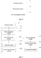
FIG. 4 is a schematic structural diagram of a wireless network capacity expansion device according to Embodiment 3 of the present invention. As shown inFIG. 4 , the device includes: - a
division module 11, configured to perform grid division on a target region covered by a macro cellular network, to obtain a plurality of grids; - a
processing module 12, configured to determine N first grids among the plurality of grids, where deploying one micro base station in each of the first grids brings a maximum network gain corresponding to the target region, and N is an integer greater than 1; and - a first determining
module 13, configured to determine, according to the N first grids determined by the processing module, that one micro base station is deployed in each of the N first grids. - The device in this embodiment may be configured to execute a technical solution of the method embodiment shown in
FIG. 1 , and implementation principles and technical effects thereof are similar, and details are not described herein again. -
FIG. 5 is a schematic structural diagram of a wireless network capacity expansion device according to Embodiment 4 of the present invention. As shown inFIG. 5 , the device in this embodiment is based on the embodiment shown inFIG. 4 , and theprocessing module 12 includes: - a
first processing unit 121, configured to determine L second grids among the plurality of grids, where deploying one micro base station in each of the second grids increases a network gain corresponding to the target region, and L is an integer greater than N; and - a
second processing unit 122, configured to determine the N first grids among the L second grids. - Further, the
first processing unit 121 includes:
a first calculation subunit 1211, configured to: successively for each grid of the plurality of grids, calculate, according to formula (1), a network capacity gain that is corresponding to the target region and that is obtained after one micro base station is deployed independently in each grid, and calculate, according to formula (2), a network coverage gain that is corresponding to the target region and that is obtained after one micro base station is deployed in each grid:


a first determiningsubunit 1212, configured to determine that grids that enable the network capacity gain to be greater than 0 and the network coverage gain to be greater than 0 constitute the L second grids. - Further, the
second processing unit 122 specifically includes: - a
selection subunit 1221, configured to traverse the L second grids, and determine N third grids among the L second grids, where a distance between any two third grids is greater than an interference distance threshold; and - a second determining
subunit 1222, configured to determine the N third grids as the N first grids if deploying one micro base station in each of the third grids brings the maximum network gain corresponding to the target region. - Specifically, the
selection subunit 1221 is specifically configured to: - determine interference between any two of the L second grids according to formula (6):

- determine a distance between grids that enables the interference to be less than a preset interference threshold as the interference distance threshold.
- Further, the device further includes:
- a second determining
module 21, configured to: by using each grid of the plurality of grids as a to-be-processed grid, determine first reference signal strength that is of the to-be-processed grid and that is obtained before one micro base station is deployed in each of the first grids, and second reference signal strength that is of the to-be-processed grid and that is obtained after one micro base station is deployed in each of the first grids; and - an adjustment module 22, configured to: if the second reference signal strength is greater than the first reference signal strength, determine a base station corresponding to the to-be-processed grid as a to-be-adjusted base station, and adjust a parameter of the to-be-adjusted base station.
- Specifically, the adjustment module 22 is specifically configured to:
adjust a transmit power of the to-be-adjusted base station according to a first preset step; or adjust an antenna downtilt of the to-be-adjusted base station according to a second preset step. - The device in this embodiment may be configured to execute technical solutions of the method embodiments shown in
FIG. 2 andFIG. 3 , and implementation principles and technical effects thereof are similar, and details are not described herein again. -
FIG. 6 is a schematic structural diagram of a network device according to Embodiment 5 of the present invention. As shown inFIG. 6 , the network device includes:
amemory 31 and aprocessor 32 connected to thememory 31, where thememory 31 is configured to store a set of program code, and theprocessor 32 is configured to invoke the program code stored in thememory 31 to execute steps in the wireless network capacity expansion method shown inFIG. 1 : perform grid division on a target region covered by a macro cellular network, to obtain a plurality of grids; determine N first grids among the plurality of grids, where deploying one micro base station in each of the first grids brings a maximum network gain corresponding to the target region, and N is an integer greater than 1; and determine that one micro base station is deployed in each of the N first grids. - Further, the
processor 32 is further configured to: determine L second grids among the plurality of grids, where deploying one micro base station in each of the second grids increases a network gain corresponding to the target region, and L is an integer greater than N; and determine the N first grids among the L second grids. - Further, the processor 32 is further configured to: successively for each grid of the plurality of grids, calculate, according to formula (1), a network capacity gain that is corresponding to the target region and that is obtained after one micro base station is deployed independently in each grid, and calculate, according to formula (2), a network coverage gain that is corresponding to the target region and that is obtained after one micro base station is deployed in each grid:


determine that grids that enable the network capacity gain to be greater than 0 and the network coverage gain to be greater than 0 constitute the L second grids. - Further, the
processor 32 is further configured to traverse the L second grids, and determine N third grids among the L second grids, where a distance between any two third grids is greater than an interference distance threshold; and determine the N third grids as the N first grids if deploying one micro base station in each of the third grids brings the maximum network gain corresponding to the target region. - Further, the
processor 32 is further configured to: determine interference between any two of the L second grids according to formula (6):
determine a distance between grids that enables the interference to be less than a preset interference threshold as the interference distance threshold. - Further, the
processor 32 is further configured to: by using each grid of the plurality of grids as a to-be-processed grid, determine first reference signal strength that is of the to-be-processed grid and that is obtained before one micro base station is deployed in each of the first grids, and second reference signal strength that is of the to-be-processed grid and that is obtained after one micro base station is deployed in each of the first grids; and if the second reference signal strength is greater than the first reference signal strength, determine a base station corresponding to the to-be-processed grid as a to-be-adjusted base station, and adjust a parameter of the to-be-adjusted base station. - Further, the
processor 32 is further configured to adjust a transmit power of the to-be-adjusted base station according to a first preset step; or adjust an antenna downtilt of the to-be-adjusted base station according to a second preset step. - Persons of ordinary skill in the art may understand that all or a part of the steps of the foregoing method embodiments may be implemented by a program instructing relevant hardware. The previous program may be stored in a computer readable storage medium. When the program is run, the steps of the foregoing method embodiments are performed. The previous storage medium includes various mediums that are capable of storing the program code, such as a ROM, a RAM, a magnetic disk, or an optical disc.
Claims (9)
- A wireless network capacity expansion method, comprising:performing grid division on a target region covered by a macro cellular network, to obtain a plurality of grids;determining N first grids among the plurality of grids, wherein deploying one micro base station in each of the first grids brings a maximum network gain corresponding to the target region, and N is an integer greater than 1; anddetermining that one micro base station is deployed in each of the N first grids;characterized in that the determining the N first grids among the plurality of grids comprises:determining L second grids among the plurality of grids, wherein deploying one micro base station in each of the second grids increases a network gain corresponding to the target region, and L is an integer greater than N; anddetermining the N first grids among the L second grids;wherein the determining the L second grids among the plurality of grids comprises:
successively for each grid of the plurality of grids, calculating, according to formula (1), a network capacity gain that is corresponding to the target region and that is obtained after one micro base station is deployed independently in each grid, and calculating, according to formula (2), a network coverage gain that is corresponding to the target region and that is obtained after one micro base station is deployed in each grid:


 determining that grids that enable the network capacity gain to be greater than 0 and the network coverage gain to be greater than 0 constitute the L second grids.
 - The method according to claim 1, wherein the determining the N first grids among the L second grids comprises:traversing the L second grids, and determining N third grids among the L second grids, such that a distance between any two third grids is greater than an interference distance threshold; anddetermining the N third grids as the N first grids if deploying one micro base station in each of the third grids brings the maximum network gain corresponding to the target region.
- The method according to claim 2, wherein determining the interference distance threshold is as follows:determining interference between any two of the L second grids according to formula (6):
 determining a distance between grids that enables the interference to be less than a preset interference threshold as the interference distance threshold.
 - The method according to any one of claims 1 to 3, after the determining that one micro base station is deployed in each of the N first grids, further comprising:by using each grid of the plurality of grids as a to-be-processed grid, determining first reference signal strength that is of the to-be-processed grid and that is obtained before one micro base station is deployed in each of the first grids, and second reference signal strength that is of the to-be-processed grid and that is obtained after one micro base station is deployed in each of the first grids; andif the second reference signal strength is greater than the first reference signal strength, determining the base station deployed in the to-be-processed grid as a to-be-adjusted base station, and adjusting a parameter of the to-be-adjusted base station;wherein the adjusting a parameter of the to-be-adjusted base station comprises at least one of the following:adjusting a transmit power of the to-be-adjusted base station according to a first preset step; oradjusting an antenna downtilt of the to-be-adjusted base station according to a second preset step.
- A wireless network capacity expansion device, comprising:a division module, configured to perform grid division on a target region covered by a macro cellular network, to obtain a plurality of grids;a processing module, configured to determine N first grids among the plurality of grids, wherein deploying one micro base station in each of the first grids brings a maximum network gain corresponding to the target region, and N is an integer greater than 1; anda first determining module, configured to determine, according to the N first grids determined by the processing module, that one micro base station is deployed in each of the N first grids;characterized in that the processing module comprises:a first processing unit, configured to determine L second grids among the plurality of grids, wherein deploying one micro base station in each of the second grids increases a network gain corresponding to the target region, and L is an integer greater than N; anda second processing unit, configured to determine the N first grids among the L second grids;wherein the first processing unit comprises:a first calculation subunit, configured to: successively for each grid of the plurality of grids, calculate, according to formula (1), a network capacity gain that is corresponding to the target region and that is obtained after one micro base station is deployed independently in each grid, and calculate, according to formula (2), a network coverage gain that is corresponding to the target region and that is obtained after one micro base station is deployed in each grid:


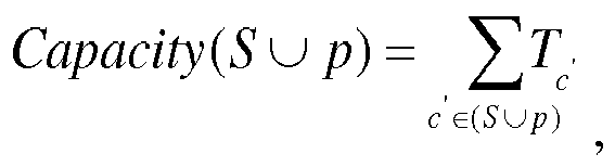


 a first determining subunit, configured to determine that grids that enable the network capacity gain to be greater than 0 and the network coverage gain to be greater than 0 constitute the L second grids.
 - The device according to claim 5, wherein the second processing unit comprises:a selection subunit, configured to traverse the L second grids, and determine N third grids among the L second grids, such that a distance between any two third grids is greater than an interference distance threshold; anda second determining subunit, configured to determine the N third grids as the N first grids if deploying one micro base station in each of the third grids brings the maximum network gain corresponding to the target region.
- The device according to claim 6, wherein the selection subunit is further configured to:determine interference between any two second grids in the L second grids according to formula (6):
 determine a distance between grids that enables the interference to be less than a preset interference threshold as the interference distance threshold.
 - The device according to any one of claims 5 to 7, further comprising:a second determining module, configured to: by using each grid of the plurality of grids as a to-be-processed grid, determine first reference signal strength that is of the to-be-processed grid and that is obtained before one micro base station is deployed in each of the first grids, and second reference signal strength that is of the to-be-processed grid and that is obtained after one micro base station is deployed in each of the first grids; andan adjustment module, configured to: if the second reference signal strength is greater than the first reference signal strength, determine the base station deployed in the to-be-processed grid as a to-be-adjusted base station, and adjust a parameter of the to-be-adjusted base station;wherein the adjustment module is specifically configured to:
adjust a transmit power of the to-be-adjusted base station according to a first preset step; or adjust an antenna downtilt of the to-be-adjusted base station according to a second preset step. - A network device, comprising:
a memory and a processor connected to the memory, wherein the memory is configured to store a set of program code, and the processor is configured to invoke the program code stored in the memory to execute the method according to any one of claims 1 to 4.
Applications Claiming Priority (1)
| Application Number | Priority Date | Filing Date | Title |
|---|---|---|---|
| PCT/CN2014/078034 WO2015176258A1 (en) | 2014-05-21 | 2014-05-21 | Capacity expansion method and device for wireless network |
Publications (3)
| Publication Number | Publication Date |
|---|---|
| EP3148241A1 EP3148241A1 (en) | 2017-03-29 |
| EP3148241A4 EP3148241A4 (en) | 2017-05-17 |
| EP3148241B1 true EP3148241B1 (en) | 2020-03-25 |
Family
ID=54553213
Family Applications (1)
| Application Number | Title | Priority Date | Filing Date |
|---|---|---|---|
| EP14892639.7A Active EP3148241B1 (en) | 2014-05-21 | 2014-05-21 | Capacity expansion method and device for wireless network |
Country Status (3)
| Country | Link |
|---|---|
| EP (1) | EP3148241B1 (en) |
| CN (1) | CN106465142B (en) |
| WO (1) | WO2015176258A1 (en) |
Families Citing this family (12)
| Publication number | Priority date | Publication date | Assignee | Title |
|---|---|---|---|---|
| CN108260075B (en) * | 2016-12-27 | 2020-10-02 | 中国移动通信集团浙江有限公司 | Method and device for addressing location of base station deployment |
| CN107347188B (en) * | 2017-06-19 | 2020-09-11 | 国网浙江省电力公司嘉兴供电公司 | TD-LTE230 network-based power grid base station initial site selection method |
| CN107682862B (en) * | 2017-07-13 | 2020-12-25 | 国网浙江省电力公司嘉兴供电公司 | Site selection method for communication network base station of TD-LTE230 power system |
| CN109327841B (en) * | 2018-09-30 | 2020-11-17 | 湖南华诺科技有限公司 | Multi-dimensional evaluation and accurate construction evaluation method based on coverage and value association |
| CN109661001B (en) * | 2019-01-11 | 2022-06-07 | 中国联合网络通信集团有限公司 | A network optimization method and server |
| CN111225408B (en) * | 2019-12-31 | 2024-01-26 | 京信网络系统股份有限公司 | Wireless environment monitoring method, device, equipment and storage medium based on SmallCell base station |
| CN113965270B (en) * | 2020-07-20 | 2023-08-22 | 华为技术有限公司 | A kind of EMF strength control method and communication device |
| GB2603604B (en) * | 2020-11-30 | 2023-04-05 | Jio Platforms Ltd | System and method for automated planning of next generation telecom network |
| CN114448813B (en) * | 2021-12-28 | 2024-03-22 | 天津市邮电设计院有限责任公司 | Method, device, server and medium for determining network capacity expansion ratio |
| CN114501477B (en) * | 2022-02-23 | 2024-04-02 | 阿里巴巴(中国)有限公司 | Method and device for determining installation point of wireless base station and terminal equipment |
| CN116546606A (en) * | 2023-05-17 | 2023-08-04 | 长春理工大学 | Dyna-Q-based ultra-dense heterogeneous network power control algorithm |
| CN116614826B (en) * | 2023-05-24 | 2024-01-16 | 北京天坦智能科技有限责任公司 | Coverage and capacity optimization method for simultaneous transmission and reflection surface network |
Family Cites Families (6)
| Publication number | Priority date | Publication date | Assignee | Title |
|---|---|---|---|---|
| CN101494871B (en) * | 2008-01-24 | 2011-02-23 | 中兴通讯股份有限公司 | Planning method for micro district construction |
| CN102547752B (en) * | 2010-12-07 | 2015-08-19 | 中国移动通信集团广东有限公司 | A kind of coverage evaluating method of wireless network and device |
| US8437765B2 (en) * | 2011-08-11 | 2013-05-07 | Verizon Patent And Licensing Inc. | Identifying locations for small cells |
| CN103118369B (en) * | 2011-11-16 | 2016-04-06 | 华为技术有限公司 | The system of selection of site and equipment and grid system of selection and equipment |
| CN103476041B (en) * | 2013-08-30 | 2016-08-10 | 浙江大学 | A kind of cellular mobile communication networks multi-plot joint coverage optimization method and device |
| CN103702337B (en) * | 2014-01-03 | 2017-04-19 | 北京邮电大学 | Determining method for small-scale base station deployment position |
-
2014
- 2014-05-21 CN CN201480078952.3A patent/CN106465142B/en active Active
- 2014-05-21 WO PCT/CN2014/078034 patent/WO2015176258A1/en not_active Ceased
- 2014-05-21 EP EP14892639.7A patent/EP3148241B1/en active Active
Non-Patent Citations (1)
| Title |
|---|
| None * |
Also Published As
| Publication number | Publication date |
|---|---|
| CN106465142A (en) | 2017-02-22 |
| CN106465142B (en) | 2019-11-19 |
| EP3148241A1 (en) | 2017-03-29 |
| EP3148241A4 (en) | 2017-05-17 |
| WO2015176258A1 (en) | 2015-11-26 |
Similar Documents
| Publication | Publication Date | Title |
|---|---|---|
| EP3148241A1 (en) | Capacity expansion method and device for wireless network | |
| US10425860B2 (en) | System and method for value optimized mobile networks | |
| US10149312B2 (en) | Resource scheduling method and apparatus | |
| WO2017050113A1 (en) | System and method for a multi view learning approach to anomaly detection and root cause analysis | |
| EP3360360B1 (en) | System and method for load rebalancing | |
| US20230063522A1 (en) | Optimizing a cellular network using a machine learning model | |
| EP3669566B1 (en) | Community detection in radio access networks with constraints | |
| US9924372B2 (en) | Method for sharing of unlicensed radio frequency bands by cellular LTE and WiFi networks | |
| JP2011188164A (en) | Base station apparatus and communication band allocation method | |
| Madapatha et al. | Constrained deployment optimization in integrated access and backhaul networks | |
| EP4260532A1 (en) | Load management of overlapping cells based on user throughput | |
| Ghosh et al. | Coverage and rate analysis in two‐tier heterogeneous networks under suburban and urban scenarios | |
| US20240098566A1 (en) | Load management of overlapping cells based on user throughput | |
| CN111385039B (en) | Method and device for adjusting cell broadcast beam parameters | |
| JP2023509544A (en) | ELECTRONIC DEVICE, WIRELESS COMMUNICATION METHOD AND COMPUTER-READABLE STORAGE MEDIUM | |
| US10165449B2 (en) | Method of planning of mobile telecommunications networks | |
| US10257714B2 (en) | Channel selection algorithm with consecutive search loops | |
| Arikawa et al. | High-speed radio-resource scheduling for 5G ultra-high-density distributed antenna systems | |
| US11234186B2 (en) | Scheduling apparatus and method, and program | |
| WO2022159081A1 (en) | Load management of overlapping cells based on user throughput | |
| KR102593994B1 (en) | System and method for selecting optimized beam using finger printer based on user position | |
| EP3202176B1 (en) | Differentiated adaptation of selection probabilities for frequency channel selection | |
| KR101682290B1 (en) | Systtem and method of interference alignment and controlling in multiple cell random access network | |
| de Oliveira Torres et al. | Interference mitigation in next generation networks using clustering and intelligence techniques | |
| Mubarok et al. | Planning of LTE-Apro Network using Licensed Assisted Access combining Spectrum Licensed 1800MHz and Unlicensed 5GHz |
Legal Events
| Date | Code | Title | Description |
|---|---|---|---|
| STAA | Information on the status of an ep patent application or granted ep patent |
Free format text: STATUS: THE INTERNATIONAL PUBLICATION HAS BEEN MADE |
|
| PUAI | Public reference made under article 153(3) epc to a published international application that has entered the european phase |
Free format text: ORIGINAL CODE: 0009012 |
|
| STAA | Information on the status of an ep patent application or granted ep patent |
Free format text: STATUS: REQUEST FOR EXAMINATION WAS MADE |
|
| 17P | Request for examination filed |
Effective date: 20161117 |
|
| AK | Designated contracting states |
Kind code of ref document: A1 Designated state(s): AL AT BE BG CH CY CZ DE DK EE ES FI FR GB GR HR HU IE IS IT LI LT LU LV MC MK MT NL NO PL PT RO RS SE SI SK SM TR |
|
| AX | Request for extension of the european patent |
Extension state: BA ME |
|
| A4 | Supplementary search report drawn up and despatched |
Effective date: 20170421 |
|
| RIC1 | Information provided on ipc code assigned before grant |
Ipc: H04W 16/32 20090101ALI20170413BHEP Ipc: H04W 16/22 20090101ALI20170413BHEP Ipc: H04W 16/18 20090101AFI20170413BHEP |
|
| DAX | Request for extension of the european patent (deleted) | ||
| RIN1 | Information on inventor provided before grant (corrected) |
Inventor name: YI, YOUWEN Inventor name: ZHUANG, HONGCHENG Inventor name: SHMELKIN, DMITRI |
|
| REG | Reference to a national code |
Ref country code: DE Ref legal event code: R079 Ref document number: 602014062994 Country of ref document: DE Free format text: PREVIOUS MAIN CLASS: H04W0016180000 Ipc: H04W0016220000 |
|
| GRAP | Despatch of communication of intention to grant a patent |
Free format text: ORIGINAL CODE: EPIDOSNIGR1 |
|
| STAA | Information on the status of an ep patent application or granted ep patent |
Free format text: STATUS: GRANT OF PATENT IS INTENDED |
|
| RIC1 | Information provided on ipc code assigned before grant |
Ipc: H04W 16/22 20090101AFI20191015BHEP Ipc: H04W 16/18 20090101ALI20191015BHEP Ipc: H04W 16/32 20090101ALI20191015BHEP |
|
| INTG | Intention to grant announced |
Effective date: 20191108 |
|
| GRAS | Grant fee paid |
Free format text: ORIGINAL CODE: EPIDOSNIGR3 |
|
| GRAA | (expected) grant |
Free format text: ORIGINAL CODE: 0009210 |
|
| STAA | Information on the status of an ep patent application or granted ep patent |
Free format text: STATUS: THE PATENT HAS BEEN GRANTED |
|
| AK | Designated contracting states |
Kind code of ref document: B1 Designated state(s): AL AT BE BG CH CY CZ DE DK EE ES FI FR GB GR HR HU IE IS IT LI LT LU LV MC MK MT NL NO PL PT RO RS SE SI SK SM TR |
|
| REG | Reference to a national code |
Ref country code: GB Ref legal event code: FG4D |
|
| REG | Reference to a national code |
Ref country code: AT Ref legal event code: REF Ref document number: 1250012 Country of ref document: AT Kind code of ref document: T Effective date: 20200415 Ref country code: IE Ref legal event code: FG4D |
|
| REG | Reference to a national code |
Ref country code: DE Ref legal event code: R096 Ref document number: 602014062994 Country of ref document: DE |
|
| PG25 | Lapsed in a contracting state [announced via postgrant information from national office to epo] |
Ref country code: RS Free format text: LAPSE BECAUSE OF FAILURE TO SUBMIT A TRANSLATION OF THE DESCRIPTION OR TO PAY THE FEE WITHIN THE PRESCRIBED TIME-LIMIT Effective date: 20200325 Ref country code: NO Free format text: LAPSE BECAUSE OF FAILURE TO SUBMIT A TRANSLATION OF THE DESCRIPTION OR TO PAY THE FEE WITHIN THE PRESCRIBED TIME-LIMIT Effective date: 20200625 Ref country code: FI Free format text: LAPSE BECAUSE OF FAILURE TO SUBMIT A TRANSLATION OF THE DESCRIPTION OR TO PAY THE FEE WITHIN THE PRESCRIBED TIME-LIMIT Effective date: 20200325 |
|
| PG25 | Lapsed in a contracting state [announced via postgrant information from national office to epo] |
Ref country code: LV Free format text: LAPSE BECAUSE OF FAILURE TO SUBMIT A TRANSLATION OF THE DESCRIPTION OR TO PAY THE FEE WITHIN THE PRESCRIBED TIME-LIMIT Effective date: 20200325 Ref country code: SE Free format text: LAPSE BECAUSE OF FAILURE TO SUBMIT A TRANSLATION OF THE DESCRIPTION OR TO PAY THE FEE WITHIN THE PRESCRIBED TIME-LIMIT Effective date: 20200325 Ref country code: HR Free format text: LAPSE BECAUSE OF FAILURE TO SUBMIT A TRANSLATION OF THE DESCRIPTION OR TO PAY THE FEE WITHIN THE PRESCRIBED TIME-LIMIT Effective date: 20200325 Ref country code: BG Free format text: LAPSE BECAUSE OF FAILURE TO SUBMIT A TRANSLATION OF THE DESCRIPTION OR TO PAY THE FEE WITHIN THE PRESCRIBED TIME-LIMIT Effective date: 20200625 Ref country code: GR Free format text: LAPSE BECAUSE OF FAILURE TO SUBMIT A TRANSLATION OF THE DESCRIPTION OR TO PAY THE FEE WITHIN THE PRESCRIBED TIME-LIMIT Effective date: 20200626 |
|
| REG | Reference to a national code |
Ref country code: NL Ref legal event code: MP Effective date: 20200325 |
|
| REG | Reference to a national code |
Ref country code: LT Ref legal event code: MG4D |
|
| PG25 | Lapsed in a contracting state [announced via postgrant information from national office to epo] |
Ref country code: NL Free format text: LAPSE BECAUSE OF FAILURE TO SUBMIT A TRANSLATION OF THE DESCRIPTION OR TO PAY THE FEE WITHIN THE PRESCRIBED TIME-LIMIT Effective date: 20200325 |
|
| PG25 | Lapsed in a contracting state [announced via postgrant information from national office to epo] |
Ref country code: SK Free format text: LAPSE BECAUSE OF FAILURE TO SUBMIT A TRANSLATION OF THE DESCRIPTION OR TO PAY THE FEE WITHIN THE PRESCRIBED TIME-LIMIT Effective date: 20200325 Ref country code: RO Free format text: LAPSE BECAUSE OF FAILURE TO SUBMIT A TRANSLATION OF THE DESCRIPTION OR TO PAY THE FEE WITHIN THE PRESCRIBED TIME-LIMIT Effective date: 20200325 Ref country code: CZ Free format text: LAPSE BECAUSE OF FAILURE TO SUBMIT A TRANSLATION OF THE DESCRIPTION OR TO PAY THE FEE WITHIN THE PRESCRIBED TIME-LIMIT Effective date: 20200325 Ref country code: LT Free format text: LAPSE BECAUSE OF FAILURE TO SUBMIT A TRANSLATION OF THE DESCRIPTION OR TO PAY THE FEE WITHIN THE PRESCRIBED TIME-LIMIT Effective date: 20200325 Ref country code: IS Free format text: LAPSE BECAUSE OF FAILURE TO SUBMIT A TRANSLATION OF THE DESCRIPTION OR TO PAY THE FEE WITHIN THE PRESCRIBED TIME-LIMIT Effective date: 20200725 Ref country code: PT Free format text: LAPSE BECAUSE OF FAILURE TO SUBMIT A TRANSLATION OF THE DESCRIPTION OR TO PAY THE FEE WITHIN THE PRESCRIBED TIME-LIMIT Effective date: 20200818 Ref country code: EE Free format text: LAPSE BECAUSE OF FAILURE TO SUBMIT A TRANSLATION OF THE DESCRIPTION OR TO PAY THE FEE WITHIN THE PRESCRIBED TIME-LIMIT Effective date: 20200325 Ref country code: SM Free format text: LAPSE BECAUSE OF FAILURE TO SUBMIT A TRANSLATION OF THE DESCRIPTION OR TO PAY THE FEE WITHIN THE PRESCRIBED TIME-LIMIT Effective date: 20200325 |
|
| REG | Reference to a national code |
Ref country code: AT Ref legal event code: MK05 Ref document number: 1250012 Country of ref document: AT Kind code of ref document: T Effective date: 20200325 |
|
| REG | Reference to a national code |
Ref country code: DE Ref legal event code: R097 Ref document number: 602014062994 Country of ref document: DE |
|
| PG25 | Lapsed in a contracting state [announced via postgrant information from national office to epo] |
Ref country code: LI Free format text: LAPSE BECAUSE OF NON-PAYMENT OF DUE FEES Effective date: 20200531 Ref country code: AT Free format text: LAPSE BECAUSE OF FAILURE TO SUBMIT A TRANSLATION OF THE DESCRIPTION OR TO PAY THE FEE WITHIN THE PRESCRIBED TIME-LIMIT Effective date: 20200325 Ref country code: ES Free format text: LAPSE BECAUSE OF FAILURE TO SUBMIT A TRANSLATION OF THE DESCRIPTION OR TO PAY THE FEE WITHIN THE PRESCRIBED TIME-LIMIT Effective date: 20200325 Ref country code: CH Free format text: LAPSE BECAUSE OF NON-PAYMENT OF DUE FEES Effective date: 20200531 Ref country code: DK Free format text: LAPSE BECAUSE OF FAILURE TO SUBMIT A TRANSLATION OF THE DESCRIPTION OR TO PAY THE FEE WITHIN THE PRESCRIBED TIME-LIMIT Effective date: 20200325 Ref country code: MC Free format text: LAPSE BECAUSE OF FAILURE TO SUBMIT A TRANSLATION OF THE DESCRIPTION OR TO PAY THE FEE WITHIN THE PRESCRIBED TIME-LIMIT Effective date: 20200325 Ref country code: IT Free format text: LAPSE BECAUSE OF FAILURE TO SUBMIT A TRANSLATION OF THE DESCRIPTION OR TO PAY THE FEE WITHIN THE PRESCRIBED TIME-LIMIT Effective date: 20200325 |
|
| PLBE | No opposition filed within time limit |
Free format text: ORIGINAL CODE: 0009261 |
|
| STAA | Information on the status of an ep patent application or granted ep patent |
Free format text: STATUS: NO OPPOSITION FILED WITHIN TIME LIMIT |
|
| PG25 | Lapsed in a contracting state [announced via postgrant information from national office to epo] |
Ref country code: PL Free format text: LAPSE BECAUSE OF FAILURE TO SUBMIT A TRANSLATION OF THE DESCRIPTION OR TO PAY THE FEE WITHIN THE PRESCRIBED TIME-LIMIT Effective date: 20200325 |
|
| 26N | No opposition filed |
Effective date: 20210112 |
|
| REG | Reference to a national code |
Ref country code: BE Ref legal event code: MM Effective date: 20200531 |
|
| GBPC | Gb: european patent ceased through non-payment of renewal fee |
Effective date: 20200625 |
|
| PG25 | Lapsed in a contracting state [announced via postgrant information from national office to epo] |
Ref country code: LU Free format text: LAPSE BECAUSE OF NON-PAYMENT OF DUE FEES Effective date: 20200521 |
|
| PG25 | Lapsed in a contracting state [announced via postgrant information from national office to epo] |
Ref country code: IE Free format text: LAPSE BECAUSE OF NON-PAYMENT OF DUE FEES Effective date: 20200521 Ref country code: GB Free format text: LAPSE BECAUSE OF NON-PAYMENT OF DUE FEES Effective date: 20200625 |
|
| PG25 | Lapsed in a contracting state [announced via postgrant information from national office to epo] |
Ref country code: BE Free format text: LAPSE BECAUSE OF NON-PAYMENT OF DUE FEES Effective date: 20200531 Ref country code: SI Free format text: LAPSE BECAUSE OF FAILURE TO SUBMIT A TRANSLATION OF THE DESCRIPTION OR TO PAY THE FEE WITHIN THE PRESCRIBED TIME-LIMIT Effective date: 20200325 |
|
| PG25 | Lapsed in a contracting state [announced via postgrant information from national office to epo] |
Ref country code: TR Free format text: LAPSE BECAUSE OF FAILURE TO SUBMIT A TRANSLATION OF THE DESCRIPTION OR TO PAY THE FEE WITHIN THE PRESCRIBED TIME-LIMIT Effective date: 20200325 Ref country code: MT Free format text: LAPSE BECAUSE OF FAILURE TO SUBMIT A TRANSLATION OF THE DESCRIPTION OR TO PAY THE FEE WITHIN THE PRESCRIBED TIME-LIMIT Effective date: 20200325 Ref country code: CY Free format text: LAPSE BECAUSE OF FAILURE TO SUBMIT A TRANSLATION OF THE DESCRIPTION OR TO PAY THE FEE WITHIN THE PRESCRIBED TIME-LIMIT Effective date: 20200325 |
|
| PG25 | Lapsed in a contracting state [announced via postgrant information from national office to epo] |
Ref country code: MK Free format text: LAPSE BECAUSE OF FAILURE TO SUBMIT A TRANSLATION OF THE DESCRIPTION OR TO PAY THE FEE WITHIN THE PRESCRIBED TIME-LIMIT Effective date: 20200325 Ref country code: AL Free format text: LAPSE BECAUSE OF FAILURE TO SUBMIT A TRANSLATION OF THE DESCRIPTION OR TO PAY THE FEE WITHIN THE PRESCRIBED TIME-LIMIT Effective date: 20200325 |
|
| REG | Reference to a national code |
Ref country code: FR Ref legal event code: PLFP Year of fee payment: 10 |
|
| PGFP | Annual fee paid to national office [announced via postgrant information from national office to epo] |
Ref country code: DE Payment date: 20250402 Year of fee payment: 12 |
|
| PGFP | Annual fee paid to national office [announced via postgrant information from national office to epo] |
Ref country code: FR Payment date: 20250401 Year of fee payment: 12 |