EP3148012A1 - Connector - Google Patents
Connector Download PDFInfo
- Publication number
- EP3148012A1 EP3148012A1 EP15795483.5A EP15795483A EP3148012A1 EP 3148012 A1 EP3148012 A1 EP 3148012A1 EP 15795483 A EP15795483 A EP 15795483A EP 3148012 A1 EP3148012 A1 EP 3148012A1
- Authority
- EP
- European Patent Office
- Prior art keywords
- connector housing
- panel
- grommet
- detecting piece
- mounting hole
- Prior art date
- Legal status (The legal status is an assumption and is not a legal conclusion. Google has not performed a legal analysis and makes no representation as to the accuracy of the status listed.)
- Withdrawn
Links
Images


Classifications
-
- H—ELECTRICITY
- H01—ELECTRIC ELEMENTS
- H01R—ELECTRICALLY-CONDUCTIVE CONNECTIONS; STRUCTURAL ASSOCIATIONS OF A PLURALITY OF MUTUALLY-INSULATED ELECTRICAL CONNECTING ELEMENTS; COUPLING DEVICES; CURRENT COLLECTORS
- H01R13/00—Details of coupling devices of the kinds covered by groups H01R12/70 or H01R24/00 - H01R33/00
- H01R13/46—Bases; Cases
- H01R13/52—Dustproof, splashproof, drip-proof, waterproof, or flameproof cases
- H01R13/5202—Sealing means between parts of housing or between housing part and a wall, e.g. sealing rings
-
- H—ELECTRICITY
- H01—ELECTRIC ELEMENTS
- H01R—ELECTRICALLY-CONDUCTIVE CONNECTIONS; STRUCTURAL ASSOCIATIONS OF A PLURALITY OF MUTUALLY-INSULATED ELECTRICAL CONNECTING ELEMENTS; COUPLING DEVICES; CURRENT COLLECTORS
- H01R13/00—Details of coupling devices of the kinds covered by groups H01R12/70 or H01R24/00 - H01R33/00
- H01R13/64—Means for preventing incorrect coupling
- H01R13/641—Means for preventing incorrect coupling by indicating incorrect coupling; by indicating correct or full engagement
-
- H—ELECTRICITY
- H01—ELECTRIC ELEMENTS
- H01R—ELECTRICALLY-CONDUCTIVE CONNECTIONS; STRUCTURAL ASSOCIATIONS OF A PLURALITY OF MUTUALLY-INSULATED ELECTRICAL CONNECTING ELEMENTS; COUPLING DEVICES; CURRENT COLLECTORS
- H01R13/00—Details of coupling devices of the kinds covered by groups H01R12/70 or H01R24/00 - H01R33/00
- H01R13/73—Means for mounting coupling parts to apparatus or structures, e.g. to a wall
- H01R13/74—Means for mounting coupling parts in openings of a panel
- H01R13/741—Means for mounting coupling parts in openings of a panel using snap fastening means
- H01R13/743—Means for mounting coupling parts in openings of a panel using snap fastening means integral with the housing
Definitions
- the present invention relates to a connector.
- a connector to be mounted on a panel of a vehicle is disclosed in patent literature 1.
- the connector includes a male housing to be inserted into a mounting opening and mounted on the panel.
- a resilient male-side grommet is mounted on the male housing to cover the outer periphery of the male housing.
- Patent Literature 1 Japanese Unexamined Patent Publication No. 2001-217033
- the present invention is completed based on the above situation and aims to provide a connector enabling confirmation as to whether or not the connector is correctly mounted on a panel even if a connector housing is covered with a grommet.
- the present invention is directed to a connector with a connector housing to be inserted into a mounting hole of a panel, a resilient grommet to be mounted on the connector housing to cover an outer periphery of the connector housing and configured to be held in close contact with a wall surface of the panel when the connector housing is inserted into the mounting hole of the panel, and a detecting piece provided on the outer periphery of the connector housing and configured to project outward by interfering with the panel and cause the grommet to bulge outward by pressing the grommet by a projecting part thereof when the connector housing is in-completely inserted in the mounting hole of the panel while being configured to be resiliently restored and release a pressed state of the grommet so that a bulging state of the grommet disappears when the connector housing is correctly inserted into the mounting hole of the panel.
- the grommet When the connector housing is incompletely inserted on the panel, the grommet is caused to bulge outward by the projecting part of the detecting piece. On the other hand, when the connector housing is correctly inserted on the panel, the pressed state of the grommet by the detecting piece is released and the bulging state of the grommet substantially disappears. Thus, it can be known that the connector housing is not correctly inserted on the panel, i.e. the connector housing is not correctly mounted by confirming the bulging of the grommet visually or by touch.
- the detecting piece includes a lock projection configured to restrict the detachment of the connector housing from the panel in a direction opposite to an inserting direction of the connector housing by being arranged to be lockable to the panel in the direction opposite to the inserting direction when the connector housing is correctly inserted into the mounting hole of the panel.
- the detecting piece extends substantially along an inserting direction of the connector housing in a natural state and includes a supporting point portion coupled to an outer surface of the connector housing at an intermediate position in an extending direction of the detecting piece, and a front end part of the detecting piece in the inserting direction interferes with the panel and the detecting piece is inclined in a seesaw manner with the supporting point portion as a center in the process of inserting the connector housing into the mounting hole of the panel, whereby a rear end part of the detecting piece in the inserting direction projects outward to press the grommet.
- the mounting on the panel can be easily detected by the detecting piece having a relatively simple structure.
- a projecting portion of the detecting piece located on a rear end side in the inserting direction across the supporting point portion extends longer in the inserting direction than an interfering portion located on a front end side in the inserting direction across the supporting point portion.
- An area of the grommet to be pressed by the projecting part of the detecting piece is formed into a thin portion thinner than a surrounding. According to this configuration, even if a pressing force when the projecting part of the detecting piece presses the thin portion of the grommet is small, the grommet can be stably and reliably caused to bulge. Since interference resistance due to the interference of the detecting piece and the panel can be reduced, mounting operability to the panel is improved.
- the connector housing has a substantially rectangular cross-sectional shape and the detecting piece is provided on each of four side portions constituting the outer periphery of the connector housing. According to this configuration, an incompletely inserted state of the connector housing can be reliably detected by the detecting piece provided on at least any one of the four side portions of the connector housing.
- a connector according to this embodiment includes a connector housing 10 and a grommet 60 to be mounted on the connector housing 10 to cover the outer periphery of the connector housing 10.
- the connector housing 10 is inserted into a mounting hole 51 provided on a panel 50 while being connected to mating connector housings 90, and mounted on the panel 50 via lock projections 33 to be described later.
- a side on which the mating connector housings 90 are located when the connection of the two connector housings 10, 90 is started is referred to as a front side concerning a front-back direction. Further, a vertical direction is based on each figure.
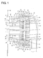
- the connector housing 10 is made of synthetic resin and formed to have a substantially rectangular cross-section and be vertically long as a whole as shown in FIG. 4 , and includes a block-like housing main body 11 and a tubular receptacle 12 projecting forward from the outer peripheral edge of the front end of the housing main body 11 as shown in FIG. 1 .
- a partitioning portion 13 is provided to substantially horizontally extend substantially in a center of the receptacle 12 in a height direction, and the interior of the receptacle 12 is divided into a pair of upper and lower fitting portions 14 via the partitioning portion 13.
- the housing main body 11 is provided with a plurality of cavities 15 at positions corresponding to the respective fitting portions 14, and a retainer mounting hole 16 communicating with each cavity 15.
- a terminal fitting 20 is inserted into each cavity 15 from behind.
- the terminal fitting 20 includes a barrel portion 22 to be crimped and connected to a wire 21 and a rubber plug 40 and a tab portion 23 projecting forward.
- the terminal fitting 20 is resiliently lockable by a locking lance 17 projecting in each cavity 15, with the result that the terminal fitting 20 is retained in the cavity 15.
- the tab portion 23 is arranged to project into the receptacle 12. Further, the terminal fitting 20 properly inserted into each cavity 15 is secondarily retained by an unillustrated retainer inserted into the retainer mounting hole 16.
- the mating connector housing 90 is made of synthetic resin and, as shown in FIGS. 1 and 4 , substantially in the form of a rectangular block fittable into each fitting portion 14 of the receptacle 12. Thus, two mating connector housings 90 are connectable to the connector housing 10.
- a lock arm 91 is provided substantially in a vertical center of the mating connector housing 90. The lock arm 91 is resiliently locked to the fitting portion 14, whereby the mating connector housing 90 is held in the fitting portion 14.
- mating terminal fittings 95 are mounted in the mating connector housing 90.
- the mating terminal fitting 95 includes a mating barrel portion 97 to be crimped and connected to a wire 96 and a rubber plug 40 and a tubular box portion 98.
- the tab portion 23 of each terminal fitting 20 is inserted and connected to the box portion 98 of the mating terminal fitting 95 and the both terminal fittings 20, 95 are electrically connected.
- the connector housing 10 is provided with a flange portion 24 bulging out over the entire circumference on the outer peripheral surface of the housing main body 11.
- Detecting pieces 27 are provided at a plurality of circumferentially spaced-apart positions of the flange portion 24, specifically substantially in centers of a pair of left and right long side portions 25 in a height direction and substantially in widthwise centers of a pair of upper and lower short side portions 26. That is, the detecting piece 27 is provided on each of four side portions constituting the outer periphery of the connector housing 10. As shown in FIG.
- the detecting piece 27 is composed of a detection arm 28 in the form of a plate projecting both forward and backward at a position substantially in a center in a bulging direction of the flange portion 24 and a supporting point portion 29 constituting a base end part in the bulging direction of the flange portion 24 and extending from the outer peripheral surface of the housing main body 11 to the detection arm 28.
- the detection arm 28 is arranged along the front-back direction in a natural state.
- a part of the detection arm 28 projecting backward from the rear surface of the flange portion 24 (hereinafter, referred to as a projecting portion 31) is formed to be longer in the front-back direction than a part projecting forward from the front surface of the flange portion 24 (hereinafter, referred to as an interfering portion 32).
- the detection arm 28 includes the interfering portion 32 on a front side and the projecting portion 31 extending longer than the interfering portion 32 on a rear side out of both front and rear sides of the supporting point portion 29.
- the claw-like lock projection 33 projecting outward is provided on a front end part of the interfering portion 32 of the detection arm 28.
- the front surface of the lock projection 33 is inclined outwardly to have a tapered shape, and the rear surface of the lock projection 33 extends along the height direction.
- the flange portion 24 is provided with through holes 36 formed as a mold for molding the lock projections 33 passes.
- the projecting portion 31 of the detection arm 28 is in the form of an even and flat strip plate as a whole.
- the grommet 60 is made of rubber and, as shown in FIG. 1 , formed into a boot shape to be mounted on the connector housing 10 to surround the entire housing main body 11.
- Each wire 21 pulled out from the rear surface of the connector housing 10 is accommodated in the grommet 60.
- the grommet 60 is composed of a tubular surrounding portion 61 extending along the front-back direction, a mounting portion 62 in the form of an annular projection connected to the front end of the surrounding portion 61 and projecting outward, a seal portion 63 conically widened forward from the front end of the mounting portion 62 and a tubular wire draw-out portion 64 connected to the rear end of the surrounding portion 61, vertically extending and projecting further downward than the surrounding portion 61.
- Each wire 21 pulled out from the rear surface of the connector housing 10 is bent by an inner wall of the wire draw-out portion 64 and drawn out downward through a lower end opening of the wire draw-out portion 64.
- the mounting portion 62 has a substantially U-shaped cross-section and a fitting groove 65 is provided over the entire circumference on the inner peripheral surface.
- the grommet 60 is positioned and mounted on the connector housing 10.
- the seal portion 63 is resiliently held in close contact with an opening edge part of the mounting hole 51 on the rear surface of the panel 50 over the entire circumference when the connector housing 10 is mounted on the panel 50. The intrusion of water into the mounting hole 51 is prevented by holding the seal portion 63 in close contact with the rear surface of the panel 50.
- the surrounding portion 61 is provided with thin portions 66 thinner than the surroundings in parts which can be pressed by being brought into contact with the projecting portions 31 of the respective detecting pieces 27 as described later.
- the thin portions 66 are thinned by recesses 67 provided on the inner peripheral surface of the surrounding portion 61 and have substantially half the thickness of parts of the surrounding portion 61 other than the thin portions 66. Note that the outer peripheral surface of the surrounding portion 61 is substantially entirely even.
- the mating connector housings 90 are fitted into the fitting portions 14 of the receptacle 12 and the connector housings 10, 90 are held in a connected state before the connector is mounted on the panel 50. Further, the grommet 60 is mounted on the housing main body 11 of the connector housing 10.
- the connector housing 10 in the connected state (hereinafter, merely referred to as the connector housing 10 unless particularly necessary) is inserted into the mounting hole 51 of the panel 50.
- each detecting piece 27 interferes with the opening edge part of the mounting hole 51 of the panel 50 and the detection arm 28 of each detecting piece 27 is inclined in a seesaw manner (see upper detecting piece 27 shown in FIG. 2 ) with the supporting point portion 29 as a supporting point so that the interfering portion 32 moves toward the housing main body 11 and the projecting portion 31 moves away from the housing main body 11.
- the detection arm 28 of each detecting piece 27 is inclined, the projecting portion 31 is fitted into the recess 67 of each thin portion 66 of the grommet 60 and each thin portion 66 is pressed by the projecting portion 31 to resiliently bulge outward.
- the rear surface of the lock projection 33 of each detecting piece 27 faces the opening edge part of the mounting hole 51 on the front surface of the panel 50 and the lock projection 33 of each detecting piece 27 is arranged to be lockable to the panel 50.
- the lock projection 33 of each detecting piece 27 is locked to the panel 50 and the connector housing 10 is prevented from coming off from the panel 50.
- the flange portion 24 faces the opening edge part of the mounting hole 51 on the rear surface of the panel 50 via the seal portion 63 of the grommet 60, thereby preventing the connector housing 10 from being inserted any deeper into the mounting hole 51 of the panel 50.
- the connector housing 10 is left incompletely inserted in the mounting hole 51 of the panel 50, e.g. if the connector housing 10 is obliquely inserted into the mounting hole 51 of the panel 50 to hold any one of the four side portions away from the panel 50, some of the detecting pieces 27 are still inclined and the lock projections 33 are located in the mounting hole 51 as shown in FIG. 2 , the projecting portions 31 of the detecting pieces 27 press the thin portions 66 of the grommet 60 as in the inserting process described above and a state where the thin portions 66 of the grommet 60 are bulging is maintained.
- the connector housing 10 is in an incompletely inserted state by visually confirming the pressed state of the thin portions 66 of the grommet 60 from the rear side (right side of FIG. 2 ) of the panel 50 or confirming such a state by touching with the hand.
- the connector housing 10 since only the thin portions 66 of the surrounding portion 61 of the grommet 60 bulge outward when the connector housing 10 is incompletely inserted, good visibility or touchability is ensured.
- the grommet 60 is caused to bulge outward by the projecting portions 31 of the detecting pieces 27 when the connector housing 10 is insufficiently inserted on the panel 50 as shown in FIG. 2 .
- the connector housing 10 is properly inserted on the panel 50 as shown in FIG. 3 , the pressed state of the grommet 60 by the detecting pieces 27 is released and the bulging state of the grommet 60 substantially disappears.
- the connector housing 20 is not correctly inserted on the panel 50, i.e. the connector is not correctly mounted on the panel 50.
- the lock projections 33 of the detecting pieces 27 have a locking function of retaining the connector housing 10 on the panel 50, a mounting detecting means and a locking means for the panel 50 are integrated on the detecting pieces 27, whereby the entire configuration is simplified.
- the thin portions 66 of the grommet 60 are caused to bulge by the seesaw-like inclination of the detecting pieces 27 with the supporting point portions 29 as supporting points, the mounting on the panel 50 can be easily detected by the detecting pieces 27 having a relatively simple structure.
- the grommet 60 can be stably and reliably caused to bulge even if pressing forces when the projecting portions 31 of the respective detecting pieces 27 press the thin portions 66 of the grommet 60 are small in the process of inserting the connector housing 10 into the mounting hole 51. As a result, interference resistance due to the interference of the detecting pieces 27 and the panel 50 can be reduced and mounting operability to the panel 50 is improved.
Landscapes
- Details Of Connecting Devices For Male And Female Coupling (AREA)
- Connector Housings Or Holding Contact Members (AREA)
Abstract
Description
- The present invention relates to a connector.
- A connector to be mounted on a panel of a vehicle is disclosed in patent literature 1. The connector includes a male housing to be inserted into a mounting opening and mounted on the panel. A resilient male-side grommet is mounted on the male housing to cover the outer periphery of the male housing. When the male housing is correctly inserted into the mounting opening of the panel, the waterproofness of the male housing can be ensured by holding the grommet in close contact with a wall surface of the panel.
- Patent Literature 1:
Japanese Unexamined Patent Publication No. 2001-217033 - In the above case, since the outer periphery of the male housing is covered with the grommet, a state where a lock structure (locking spring) of the male housing is locked to the panel cannot be visually confirmed from a mounting side of the male housing. Thus, there is a possibility that the male housing is not correctly locked to the panel and the connector comes off from the panel.
- The present invention is completed based on the above situation and aims to provide a connector enabling confirmation as to whether or not the connector is correctly mounted on a panel even if a connector housing is covered with a grommet.
- The present invention is directed to a connector with a connector housing to be inserted into a mounting hole of a panel, a resilient grommet to be mounted on the connector housing to cover an outer periphery of the connector housing and configured to be held in close contact with a wall surface of the panel when the connector housing is inserted into the mounting hole of the panel, and a detecting piece provided on the outer periphery of the connector housing and configured to project outward by interfering with the panel and cause the grommet to bulge outward by pressing the grommet by a projecting part thereof when the connector housing is in-completely inserted in the mounting hole of the panel while being configured to be resiliently restored and release a pressed state of the grommet so that a bulging state of the grommet disappears when the connector housing is correctly inserted into the mounting hole of the panel.
- When the connector housing is incompletely inserted on the panel, the grommet is caused to bulge outward by the projecting part of the detecting piece. On the other hand, when the connector housing is correctly inserted on the panel, the pressed state of the grommet by the detecting piece is released and the bulging state of the grommet substantially disappears. Thus, it can be known that the connector housing is not correctly inserted on the panel, i.e. the connector housing is not correctly mounted by confirming the bulging of the grommet visually or by touch.
-
-
FIG. 1 is a section showing a state before a connector housing is connected to a mating connector housing and inserted into a mounting hole of a panel in an connector of an embodiment of the present invention, -
FIG. 2 is a section showing a state where the connector housing is incompletely inserted in the mounting hole of the panel, -
FIG. 3 is a section showing a state where the connector housing is correctly inserted in the mounting hole of the panel, and -
FIG. 4 is a front view showing a state where the connector housing is connected to the mating connector housing. - Preferred embodiments of the present invention are described below.
- The detecting piece includes a lock projection configured to restrict the detachment of the connector housing from the panel in a direction opposite to an inserting direction of the connector housing by being arranged to be lockable to the panel in the direction opposite to the inserting direction when the connector housing is correctly inserted into the mounting hole of the panel. According to this configuration, since the detecting piece doubles as a mounting detecting means and a locking means for the panel, the entire configuration can be simplified as compared to the case where the mounting detecting means and the locking means are separately provided.
- The detecting piece extends substantially along an inserting direction of the connector housing in a natural state and includes a supporting point portion coupled to an outer surface of the connector housing at an intermediate position in an extending direction of the detecting piece, and a front end part of the detecting piece in the inserting direction interferes with the panel and the detecting piece is inclined in a seesaw manner with the supporting point portion as a center in the process of inserting the connector housing into the mounting hole of the panel, whereby a rear end part of the detecting piece in the inserting direction projects outward to press the grommet. According to this configuration, the mounting on the panel can be easily detected by the detecting piece having a relatively simple structure.
- A projecting portion of the detecting piece located on a rear end side in the inserting direction across the supporting point portion extends longer in the inserting direction than an interfering portion located on a front end side in the inserting direction across the supporting point portion. According to this configuration, when the detecting piece is inclined in a seesaw manner with the supporting point portion as a center, a projecting amount of the projecting portion is large and, eventually, a bulging amount of the grommet pushed up by the projecting portion is also large. Thus, a bulging part of the grommet is confirmed with good visibility or touchability and detection reliability is enhanced.
- An area of the grommet to be pressed by the projecting part of the detecting piece is formed into a thin portion thinner than a surrounding. According to this configuration, even if a pressing force when the projecting part of the detecting piece presses the thin portion of the grommet is small, the grommet can be stably and reliably caused to bulge. Since interference resistance due to the interference of the detecting piece and the panel can be reduced, mounting operability to the panel is improved.
- The connector housing has a substantially rectangular cross-sectional shape and the detecting piece is provided on each of four side portions constituting the outer periphery of the connector housing. According to this configuration, an incompletely inserted state of the connector housing can be reliably detected by the detecting piece provided on at least any one of the four side portions of the connector housing.
- An embodiment of the present invention is described with reference to
FIGS. 1 to 4 . A connector according to this embodiment includes aconnector housing 10 and agrommet 60 to be mounted on theconnector housing 10 to cover the outer periphery of theconnector housing 10. Theconnector housing 10 is inserted into amounting hole 51 provided on apanel 50 while being connected tomating connector housings 90, and mounted on thepanel 50 vialock projections 33 to be described later. Note that, in the following description, a side on which themating connector housings 90 are located when the connection of the twoconnector housings - The
connector housing 10 is made of synthetic resin and formed to have a substantially rectangular cross-section and be vertically long as a whole as shown inFIG. 4 , and includes a block-like housingmain body 11 and atubular receptacle 12 projecting forward from the outer peripheral edge of the front end of the housingmain body 11 as shown inFIG. 1 . A partitioningportion 13 is provided to substantially horizontally extend substantially in a center of thereceptacle 12 in a height direction, and the interior of thereceptacle 12 is divided into a pair of upper and lowerfitting portions 14 via thepartitioning portion 13. - As shown in
FIG. 1 , the housingmain body 11 is provided with a plurality ofcavities 15 at positions corresponding to therespective fitting portions 14, and aretainer mounting hole 16 communicating with eachcavity 15. Aterminal fitting 20 is inserted into eachcavity 15 from behind. Theterminal fitting 20 includes abarrel portion 22 to be crimped and connected to awire 21 and arubber plug 40 and atab portion 23 projecting forward. When being inserted into eachcavity 15, theterminal fitting 20 is resiliently lockable by alocking lance 17 projecting in eachcavity 15, with the result that theterminal fitting 20 is retained in thecavity 15. With the terminal fitting 20 properly inserted in eachcavity 15, thetab portion 23 is arranged to project into thereceptacle 12. Further, the terminal fitting 20 properly inserted into eachcavity 15 is secondarily retained by an unillustrated retainer inserted into theretainer mounting hole 16. - The
mating connector housing 90 is made of synthetic resin and, as shown inFIGS. 1 and4 , substantially in the form of a rectangular block fittable into eachfitting portion 14 of thereceptacle 12. Thus, twomating connector housings 90 are connectable to theconnector housing 10. Alock arm 91 is provided substantially in a vertical center of themating connector housing 90. Thelock arm 91 is resiliently locked to thefitting portion 14, whereby themating connector housing 90 is held in thefitting portion 14. - As shown in
FIG. 1 ,mating terminal fittings 95 are mounted in themating connector housing 90. Themating terminal fitting 95 includes amating barrel portion 97 to be crimped and connected to awire 96 and arubber plug 40 and atubular box portion 98. When themating connector housing 90 is properly fitted into thefitting portion 14 of thereceptacle 12, thetab portion 23 of eachterminal fitting 20 is inserted and connected to thebox portion 98 of the mating terminal fitting 95 and the bothterminal fittings - As shown in
FIG. 4 , theconnector housing 10 is provided with aflange portion 24 bulging out over the entire circumference on the outer peripheral surface of the housingmain body 11. Detectingpieces 27 are provided at a plurality of circumferentially spaced-apart positions of theflange portion 24, specifically substantially in centers of a pair of left and rightlong side portions 25 in a height direction and substantially in widthwise centers of a pair of upper and lowershort side portions 26. That is, the detectingpiece 27 is provided on each of four side portions constituting the outer periphery of theconnector housing 10. As shown inFIG. 1 , the detectingpiece 27 is composed of adetection arm 28 in the form of a plate projecting both forward and backward at a position substantially in a center in a bulging direction of theflange portion 24 and a supportingpoint portion 29 constituting a base end part in the bulging direction of theflange portion 24 and extending from the outer peripheral surface of the housingmain body 11 to thedetection arm 28. Thedetection arm 28 is arranged along the front-back direction in a natural state. A part of thedetection arm 28 projecting backward from the rear surface of the flange portion 24 (hereinafter, referred to as a projecting portion 31) is formed to be longer in the front-back direction than a part projecting forward from the front surface of the flange portion 24 (hereinafter, referred to as an interfering portion 32). In this way, thedetection arm 28 includes the interferingportion 32 on a front side and the projectingportion 31 extending longer than the interferingportion 32 on a rear side out of both front and rear sides of the supportingpoint portion 29. - As shown in
FIG. 1 , the claw-like lock projection 33 projecting outward is provided on a front end part of the interferingportion 32 of thedetection arm 28. The front surface of thelock projection 33 is inclined outwardly to have a tapered shape, and the rear surface of thelock projection 33 extends along the height direction. At backward projection positions of thelock projections 33, theflange portion 24 is provided with throughholes 36 formed as a mold for molding thelock projections 33 passes. On the other hand, the projectingportion 31 of thedetection arm 28 is in the form of an even and flat strip plate as a whole. - The
grommet 60 is made of rubber and, as shown inFIG. 1 , formed into a boot shape to be mounted on theconnector housing 10 to surround the entire housingmain body 11. Eachwire 21 pulled out from the rear surface of theconnector housing 10 is accommodated in thegrommet 60. Specifically, thegrommet 60 is composed of atubular surrounding portion 61 extending along the front-back direction, a mountingportion 62 in the form of an annular projection connected to the front end of the surroundingportion 61 and projecting outward, aseal portion 63 conically widened forward from the front end of the mountingportion 62 and a tubular wire draw-outportion 64 connected to the rear end of the surroundingportion 61, vertically extending and projecting further downward than the surroundingportion 61. Eachwire 21 pulled out from the rear surface of theconnector housing 10 is bent by an inner wall of the wire draw-outportion 64 and drawn out downward through a lower end opening of the wire draw-outportion 64. - As shown in
FIG. 1 , the mountingportion 62 has a substantially U-shaped cross-section and afitting groove 65 is provided over the entire circumference on the inner peripheral surface. By fitting a tip part of theflange portion 24 into thefitting groove 65 of the mountingportion 62, thegrommet 60 is positioned and mounted on theconnector housing 10. As shown inFIG. 3 , theseal portion 63 is resiliently held in close contact with an opening edge part of the mountinghole 51 on the rear surface of thepanel 50 over the entire circumference when theconnector housing 10 is mounted on thepanel 50. The intrusion of water into the mountinghole 51 is prevented by holding theseal portion 63 in close contact with the rear surface of thepanel 50. - Further, as shown in
FIG. 2 , the surroundingportion 61 is provided withthin portions 66 thinner than the surroundings in parts which can be pressed by being brought into contact with the projectingportions 31 of the respective detectingpieces 27 as described later. Thethin portions 66 are thinned byrecesses 67 provided on the inner peripheral surface of the surroundingportion 61 and have substantially half the thickness of parts of the surroundingportion 61 other than thethin portions 66. Note that the outer peripheral surface of the surroundingportion 61 is substantially entirely even. - Next, functions and effects of the connector according to this embodiment are described.
- As shown in
FIG. 1 , themating connector housings 90 are fitted into thefitting portions 14 of thereceptacle 12 and theconnector housings panel 50. Further, thegrommet 60 is mounted on the housingmain body 11 of theconnector housing 10. - Subsequently, the
connector housing 10 in the connected state (hereinafter, merely referred to as theconnector housing 10 unless particularly necessary) is inserted into the mountinghole 51 of thepanel 50. - In the process of inserting the
connector housing 10 into the mountinghole 51 of thepanel 50, thelock projection 33 of each detectingpiece 27 interferes with the opening edge part of the mountinghole 51 of thepanel 50 and thedetection arm 28 of each detectingpiece 27 is inclined in a seesaw manner (see upper detectingpiece 27 shown inFIG. 2 ) with the supportingpoint portion 29 as a supporting point so that the interferingportion 32 moves toward the housingmain body 11 and the projectingportion 31 moves away from the housingmain body 11. As thedetection arm 28 of each detectingpiece 27 is inclined, the projectingportion 31 is fitted into therecess 67 of eachthin portion 66 of thegrommet 60 and eachthin portion 66 is pressed by the projectingportion 31 to resiliently bulge outward. - As shown in
FIG. 3 , when theconnector housing 10 is correctly inserted into the mountinghole 51 of thepanel 50, thelock projection 33 of each detectingpiece 27 passes the mountinghole 51 of thepanel 50 and thedetection arm 28 is resiliently restored to an initial horizontal posture. Then, the projectingportion 31 also returns to a horizontal posture and comes out of therecess 67, thereby releasing thethin portion 66 of thegrommet 60 from the pressed state. In this way, thethin portion 66 is resiliently restored, the bulging state substantially disappears and the outer surface of the surroundingportion 61 is restored to an initial flat surface. - Further, as shown in
FIG. 3 , when theconnector housing 10 is correctly inserted into the mountinghole 51 of thepanel 50, the rear surface of thelock projection 33 of each detectingpiece 27 faces the opening edge part of the mountinghole 51 on the front surface of thepanel 50 and thelock projection 33 of each detectingpiece 27 is arranged to be lockable to thepanel 50. Thus, even if a backward (direction opposite to an inserting direction into the mounting hole 51) pull-out force acts on theconnector housing 10, thelock projection 33 of each detectingpiece 27 is locked to thepanel 50 and theconnector housing 10 is prevented from coming off from thepanel 50. Further, theflange portion 24 faces the opening edge part of the mountinghole 51 on the rear surface of thepanel 50 via theseal portion 63 of thegrommet 60, thereby preventing theconnector housing 10 from being inserted any deeper into the mountinghole 51 of thepanel 50. - On the other hand, if the
connector housing 10 is left incompletely inserted in the mountinghole 51 of thepanel 50, e.g. if theconnector housing 10 is obliquely inserted into the mountinghole 51 of thepanel 50 to hold any one of the four side portions away from thepanel 50, some of the detectingpieces 27 are still inclined and thelock projections 33 are located in the mountinghole 51 as shown inFIG. 2 , the projectingportions 31 of the detectingpieces 27 press thethin portions 66 of thegrommet 60 as in the inserting process described above and a state where thethin portions 66 of thegrommet 60 are bulging is maintained. Thus, it can be known that theconnector housing 10 is in an incompletely inserted state by visually confirming the pressed state of thethin portions 66 of thegrommet 60 from the rear side (right side ofFIG. 2 ) of thepanel 50 or confirming such a state by touching with the hand. Particularly, in the case of this embodiment, since only thethin portions 66 of the surroundingportion 61 of thegrommet 60 bulge outward when theconnector housing 10 is incompletely inserted, good visibility or touchability is ensured. - As described above, according to this embodiment, the
grommet 60 is caused to bulge outward by the projectingportions 31 of the detectingpieces 27 when theconnector housing 10 is insufficiently inserted on thepanel 50 as shown inFIG. 2 . On the other hand, when theconnector housing 10 is properly inserted on thepanel 50 as shown inFIG. 3 , the pressed state of thegrommet 60 by the detectingpieces 27 is released and the bulging state of thegrommet 60 substantially disappears. Thus, by confirming the bulging of thegrommet 60 visually or by touch, it can be known that theconnector housing 20 is not correctly inserted on thepanel 50, i.e. the connector is not correctly mounted on thepanel 50. - Further, since the
lock projections 33 of the detectingpieces 27 have a locking function of retaining theconnector housing 10 on thepanel 50, a mounting detecting means and a locking means for thepanel 50 are integrated on the detectingpieces 27, whereby the entire configuration is simplified. - Furthermore, since the
thin portions 66 of thegrommet 60 are caused to bulge by the seesaw-like inclination of the detectingpieces 27 with the supportingpoint portions 29 as supporting points, the mounting on thepanel 50 can be easily detected by the detectingpieces 27 having a relatively simple structure. - Further, since the areas of the
grommet 60 to be pressed by the projectingportions 31 of the respective detectingpieces 27 are formed into thethin portions 66 thinner than the surroundings, thegrommet 60 can be stably and reliably caused to bulge even if pressing forces when the projectingportions 31 of the respective detectingpieces 27 press thethin portions 66 of thegrommet 60 are small in the process of inserting theconnector housing 10 into the mountinghole 51. As a result, interference resistance due to the interference of the detectingpieces 27 and thepanel 50 can be reduced and mounting operability to thepanel 50 is improved. - The present invention is not limited to the above described and illustrated embodiment. For example, the following modes are also included in the technical scope of the present invention.
- (1) The detecting pieces may be pieces dedicated to detect mounting without having the locking function to the panel.
- (2) The detecting pieces and the connector housing may be separately formed.
- (3) Only one detecting piece may be formed on the outer periphery of the connector housing.
- (4) The detecting pieces may be provided at positions different from the flange portion. For example, the detecting pieces may project from the outer surface of the receptacle.
- (5) The connector housing may be a waiting-side connector housing to be mounted on a panel before being connected to a mating connector housing.
-
- 10
- ... connector housing
- 11
- ... housing main body
- 12
- ... receptacle
- 27
- ... detecting piece
- 28
- ... detection arm
- 31
- ... projecting portion
- 32
- ... interfering portion
- 33
- ... lock projection
- 50
- ... panel
- 51
- ... mounting hole
- 60
- ... grommet
- 66
- ... thin portion
- 90
- ... mating connector housing
Claims (6)
- A connector, comprising:a connector housing to be inserted into a mounting hole of a panel;a resilient grommet to be mounted on the connector housing to cover an outer periphery of the connector housing and configured to be held in close contact with a wall surface of the panel when the connector housing is inserted into the mounting hole of the panel; anda detecting piece provided on the outer periphery of the connector housing and configured to project outward by interfering with the panel and cause the grommet to bulge outward by pressing the grommet by a projecting part thereof when the connector housing is incompletely inserted in the mounting hole of the panel while being configured to be resiliently restored and release a pressed state of the grommet so that a bulging state of the grommet disappears when the connector housing is correctly inserted into the mounting hole of the panel.
- A connector according to claim 1, wherein the detecting piece includes a lock projection configured to restrict the detachment of the connector housing from the panel in a direction opposite to an inserting direction of the connector housing by being arranged to be lockable to the panel in the direction opposite to the inserting direction when the connector housing is correctly inserted into the mounting hole of the panel.
- A connector according to claim 1 or 2, wherein the detecting piece extends substantially along an inserting direction of the connector housing in a natural state and includes a supporting point portion coupled to an outer surface of the connector housing at an intermediate position in an extending direction of the detecting piece, and a front end part of the detecting piece in the inserting direction interferes with the panel and the detecting piece is inclined in a seesaw manner with the supporting point portion as a center in the process of inserting the connector housing into the mounting hole of the panel, whereby a rear end part of the detecting piece in the inserting direction projects outward to press the grommet.
- A connector according to claim 3, wherein a projecting portion of the detecting piece located on a rear end side in the inserting direction across the supporting point portion extends longer in the inserting direction than an interfering portion located on a front end side in the inserting direction across the supporting point portion.
- A connector according to any one of claims 1 to 4, wherein an area of the grommet to be pressed by the projecting part of the detecting piece is formed into a thin portion thinner than a surrounding.
- A connector according to any one of claims 1 to 5, wherein the connector housing has a substantially rectangular cross-sectional shape and the detecting piece is provided on each of four side portions constituting the outer periphery of the connector housing.
Applications Claiming Priority (2)
| Application Number | Priority Date | Filing Date | Title |
|---|---|---|---|
| JP2014106867A JP6108236B2 (en) | 2014-05-23 | 2014-05-23 | connector |
| PCT/JP2015/063164 WO2015178203A1 (en) | 2014-05-23 | 2015-05-07 | Connector |
Publications (2)
| Publication Number | Publication Date |
|---|---|
| EP3148012A1 true EP3148012A1 (en) | 2017-03-29 |
| EP3148012A4 EP3148012A4 (en) | 2017-04-19 |
Family
ID=54553876
Family Applications (1)
| Application Number | Title | Priority Date | Filing Date |
|---|---|---|---|
| EP15795483.5A Withdrawn EP3148012A4 (en) | 2014-05-23 | 2015-05-07 | Connector |
Country Status (5)
| Country | Link |
|---|---|
| US (1) | US9774129B2 (en) |
| EP (1) | EP3148012A4 (en) |
| JP (1) | JP6108236B2 (en) |
| CN (1) | CN106463896B (en) |
| WO (1) | WO2015178203A1 (en) |
Cited By (3)
| Publication number | Priority date | Publication date | Assignee | Title |
|---|---|---|---|---|
| EP3725595A1 (en) * | 2019-04-18 | 2020-10-21 | Yazaki Corporation | Grommet-equipped connector |
| EP3726669A1 (en) * | 2019-04-18 | 2020-10-21 | Yazaki Corporation | Connector |
| EP3744573A1 (en) * | 2019-04-18 | 2020-12-02 | Yazaki Corporation | Connector with grommet |
Families Citing this family (11)
| Publication number | Priority date | Publication date | Assignee | Title |
|---|---|---|---|---|
| DE102016204230A1 (en) * | 2016-03-15 | 2017-09-21 | Stocko Contact Gmbh & Co. Kg | Bulkhead |
| JP6441278B2 (en) * | 2016-09-13 | 2018-12-19 | 矢崎総業株式会社 | Locking mechanism, connector, and wire harness |
| JP6714870B2 (en) * | 2017-02-13 | 2020-07-01 | 住友電装株式会社 | connector |
| JP6978389B2 (en) * | 2018-08-30 | 2021-12-08 | 矢崎総業株式会社 | Grommet |
| JP6970064B2 (en) * | 2018-08-30 | 2021-11-24 | 矢崎総業株式会社 | Grommet |
| JP2020140818A (en) * | 2019-02-27 | 2020-09-03 | 住友電装株式会社 | connector |
| JP7032351B2 (en) * | 2019-04-18 | 2022-03-08 | 矢崎総業株式会社 | Connector with grommet |
| JP2020177805A (en) | 2019-04-18 | 2020-10-29 | 矢崎総業株式会社 | Connector with grommet |
| JP7146717B2 (en) * | 2019-10-01 | 2022-10-04 | 矢崎総業株式会社 | connector |
| DE102020105580B4 (en) * | 2020-03-03 | 2022-03-24 | Phoenix Contact Gmbh & Co. Kg | Fastening clamp for fixing at least one terminal block in a wall opening |
| FR3107997B1 (en) * | 2020-03-09 | 2022-02-18 | Radiall Sa | Connector with interface part rotatably mounted in the case and operable by tool for sliding a locking cover to an additional connector. |
Citations (4)
| Publication number | Priority date | Publication date | Assignee | Title |
|---|---|---|---|---|
| US4711507A (en) * | 1985-10-07 | 1987-12-08 | Thomas & Betts Corporation | Electrical connector and latching apparatus therefor |
| US5044986A (en) * | 1990-06-29 | 1991-09-03 | Molex Incorporated | Sealing device for panel mounted electrical connector |
| US20020189838A1 (en) * | 2001-06-18 | 2002-12-19 | Sumitomo Wiring Systems, Ltd. | Grommet equipped with resin inner sleeve for fixing connectors and method of installing the grommet |
| US20040242063A1 (en) * | 2002-05-30 | 2004-12-02 | Sumitomo Wiring Systems, Ltd., Mie, Japan | Panel-mountable part and method of dismounting such a panel-mountable part |
Family Cites Families (7)
| Publication number | Priority date | Publication date | Assignee | Title |
|---|---|---|---|---|
| GB1468843A (en) * | 1973-08-01 | 1977-03-30 | Amp Inc | Sealing members for electrical components |
| US4449778A (en) | 1982-12-22 | 1984-05-22 | Amp Incorporated | Shielded electrical connector |
| US5249982A (en) * | 1992-12-29 | 1993-10-05 | Molex Incorporated | Panel mounted electrical connector with improved sealing system |
| JP2784369B2 (en) * | 1993-08-30 | 1998-08-06 | 矢崎総業株式会社 | Panel lock connector |
| US5775944A (en) * | 1996-08-19 | 1998-07-07 | General Motors Corporation | Sealed connector-to-body interface |
| JP3687462B2 (en) | 2000-02-03 | 2005-08-24 | 住友電装株式会社 | Waterproof structure for panel mount connectors |
| JP3944179B2 (en) * | 2004-03-12 | 2007-07-11 | 矢崎総業株式会社 | connector |
-
2014
- 2014-05-23 JP JP2014106867A patent/JP6108236B2/en not_active Expired - Fee Related
-
2015
- 2015-05-07 WO PCT/JP2015/063164 patent/WO2015178203A1/en active Application Filing
- 2015-05-07 EP EP15795483.5A patent/EP3148012A4/en not_active Withdrawn
- 2015-05-07 CN CN201580026692.XA patent/CN106463896B/en not_active Expired - Fee Related
- 2015-05-07 US US15/308,391 patent/US9774129B2/en not_active Expired - Fee Related
Patent Citations (4)
| Publication number | Priority date | Publication date | Assignee | Title |
|---|---|---|---|---|
| US4711507A (en) * | 1985-10-07 | 1987-12-08 | Thomas & Betts Corporation | Electrical connector and latching apparatus therefor |
| US5044986A (en) * | 1990-06-29 | 1991-09-03 | Molex Incorporated | Sealing device for panel mounted electrical connector |
| US20020189838A1 (en) * | 2001-06-18 | 2002-12-19 | Sumitomo Wiring Systems, Ltd. | Grommet equipped with resin inner sleeve for fixing connectors and method of installing the grommet |
| US20040242063A1 (en) * | 2002-05-30 | 2004-12-02 | Sumitomo Wiring Systems, Ltd., Mie, Japan | Panel-mountable part and method of dismounting such a panel-mountable part |
Non-Patent Citations (1)
| Title |
|---|
| See also references of WO2015178203A1 * |
Cited By (3)
| Publication number | Priority date | Publication date | Assignee | Title |
|---|---|---|---|---|
| EP3725595A1 (en) * | 2019-04-18 | 2020-10-21 | Yazaki Corporation | Grommet-equipped connector |
| EP3726669A1 (en) * | 2019-04-18 | 2020-10-21 | Yazaki Corporation | Connector |
| EP3744573A1 (en) * | 2019-04-18 | 2020-12-02 | Yazaki Corporation | Connector with grommet |
Also Published As
| Publication number | Publication date |
|---|---|
| CN106463896A (en) | 2017-02-22 |
| JP6108236B2 (en) | 2017-04-05 |
| CN106463896B (en) | 2018-12-11 |
| US9774129B2 (en) | 2017-09-26 |
| EP3148012A4 (en) | 2017-04-19 |
| WO2015178203A1 (en) | 2015-11-26 |
| US20170062970A1 (en) | 2017-03-02 |
| JP2015222667A (en) | 2015-12-10 |
Similar Documents
| Publication | Publication Date | Title |
|---|---|---|
| EP3148012A1 (en) | Connector | |
| US10224665B2 (en) | Connector | |
| US9509076B2 (en) | Connector with front backlash preventing portions and rear backlash preventing portion that are offset circumferentially with respect to the front backlash preventing portions | |
| US9407025B2 (en) | Connector | |
| EP2706621B1 (en) | Connector, connector assembly and assembly method | |
| EP1763114B1 (en) | An electrical connector | |
| US11018446B2 (en) | Connector | |
| US9543697B2 (en) | Connector having a housing with a fitting tube with guide walls with a lock arm inbettween | |
| JP5790619B2 (en) | connector | |
| US8231401B2 (en) | Connector | |
| US9543702B2 (en) | Connector | |
| JP2011086381A (en) | Waterproof connector | |
| US10998669B2 (en) | Connector with receptacle having moving plate and sealing member mounted in the receptacle | |
| JP5783468B2 (en) | connector | |
| JP3667652B2 (en) | connector | |
| US20160315416A1 (en) | Connector | |
| US10622757B2 (en) | Connector with rubber cover | |
| EP2390964B1 (en) | Connector and connector assembly | |
| EP2390963B1 (en) | Connector, connector assembly and connector production method | |
| JP2012243542A (en) | Terminal fitting | |
| US9065198B2 (en) | Connector with foreign substance entrance preventing portion | |
| US10826222B2 (en) | Connector | |
| US20160315412A1 (en) | Connector | |
| JP2010238503A (en) | Waterproof connector and dummy plug | |
| JP2012109031A (en) | Connector |
Legal Events
| Date | Code | Title | Description |
|---|---|---|---|
| PUAI | Public reference made under article 153(3) epc to a published international application that has entered the european phase |
Free format text: ORIGINAL CODE: 0009012 |
|
| 17P | Request for examination filed |
Effective date: 20161110 |
|
| AK | Designated contracting states |
Kind code of ref document: A1 Designated state(s): AL AT BE BG CH CY CZ DE DK EE ES FI FR GB GR HR HU IE IS IT LI LT LU LV MC MK MT NL NO PL PT RO RS SE SI SK SM TR |
|
| AX | Request for extension of the european patent |
Extension state: BA ME |
|
| A4 | Supplementary search report drawn up and despatched |
Effective date: 20170317 |
|
| RIC1 | Information provided on ipc code assigned before grant |
Ipc: H01R 13/52 20060101ALI20170313BHEP Ipc: H01R 13/641 20060101ALI20170313BHEP Ipc: H01R 13/74 20060101AFI20170313BHEP |
|
| DAV | Request for validation of the european patent (deleted) | ||
| DAX | Request for extension of the european patent (deleted) | ||
| STAA | Information on the status of an ep patent application or granted ep patent |
Free format text: STATUS: THE APPLICATION IS DEEMED TO BE WITHDRAWN |
|
| 18D | Application deemed to be withdrawn |
Effective date: 20171017 |