EP3147794A1 - Transferverfahren von informationen zur konfiguration eines verbundenen objekts - Google Patents
Transferverfahren von informationen zur konfiguration eines verbundenen objekts Download PDFInfo
- Publication number
- EP3147794A1 EP3147794A1 EP16188277.4A EP16188277A EP3147794A1 EP 3147794 A1 EP3147794 A1 EP 3147794A1 EP 16188277 A EP16188277 A EP 16188277A EP 3147794 A1 EP3147794 A1 EP 3147794A1
- Authority
- EP
- European Patent Office
- Prior art keywords
- terminal
- connected object
- configuration information
- configuration
- mass memory
- Prior art date
- Legal status (The legal status is an assumption and is not a legal conclusion. Google has not performed a legal analysis and makes no representation as to the accuracy of the status listed.)
- Ceased
Links
Images


Classifications
-
- G—PHYSICS
- G06—COMPUTING; CALCULATING OR COUNTING
- G06F—ELECTRIC DIGITAL DATA PROCESSING
- G06F13/00—Interconnection of, or transfer of information or other signals between, memories, input/output devices or central processing units
- G06F13/10—Program control for peripheral devices
- G06F13/102—Program control for peripheral devices where the programme performs an interfacing function, e.g. device driver
-
- G—PHYSICS
- G06—COMPUTING; CALCULATING OR COUNTING
- G06F—ELECTRIC DIGITAL DATA PROCESSING
- G06F13/00—Interconnection of, or transfer of information or other signals between, memories, input/output devices or central processing units
- G06F13/38—Information transfer, e.g. on bus
- G06F13/382—Information transfer, e.g. on bus using universal interface adapter
- G06F13/385—Information transfer, e.g. on bus using universal interface adapter for adaptation of a particular data processing system to different peripheral devices
-
- G—PHYSICS
- G06—COMPUTING; CALCULATING OR COUNTING
- G06F—ELECTRIC DIGITAL DATA PROCESSING
- G06F13/00—Interconnection of, or transfer of information or other signals between, memories, input/output devices or central processing units
- G06F13/38—Information transfer, e.g. on bus
- G06F13/42—Bus transfer protocol, e.g. handshake; Synchronisation
- G06F13/4282—Bus transfer protocol, e.g. handshake; Synchronisation on a serial bus, e.g. I2C bus, SPI bus
Definitions
- the invention relates to the general field of connected objects.
- Such objects are connected to the public Internet network (we also speak of the Internet of Things) and can communicate with other systems, such as for example a smartphone (or "smartphone" in English) , a touch-sensitive digital tablet, and / or a computer, for obtaining or providing information.
- This communication is based on a wired or wireless connection type Bluetooth TM or Wi-Fi TM.
- Such objects can be configured to collect and store information according to their environment (eg heart rate of the user for a cardio watch) or trigger an action based on information collected on the web (eg watering of a garden the day before a drought day).
- their primary purpose is not to be computer peripherals or web access interfaces; the addition of an Internet connection to these objects provides them with additional value in terms of functionality, use, information and / or interaction with the environment. Interactivity with these objects is therefore very important.
- connected object-specific software are available and can only be downloaded and run from a computer.
- the users of connected objects do not necessarily have at their disposal permanently such a computer. They may in particular have only a mobile terminal such as for example a smartphone or smartphone or a digital tablet touch.
- mass memory is understood to mean, as conventionally in computing, a non-volatile high-capacity memory (that is to say that it is capable of preserving the information recorded even in the form of data). lack of power (eg power supply)), and which can be read or written for example by a computer in the general sense of the term (this computer can in particular be a mobile phone or a smartphone (smartphone)).
- mass memories include a CD (Compact Disc) with a storage capacity of 200 to 900 MB, a DVD (Digital Versatile Disc) with a storage capacity of 4.7 to 8.5 GB, a hard disk or a hard disk.
- USB key with a storage capacity of 4 to 128 GB.
- the invention proposes a simple solution for configuring an object connected via any terminal, such as for example a mobile phone or a digital tablet, without violating the security principles inherent to the terminal.
- This solution advantageously relies on the ability of the connected object to connect to the terminal via one of its peripheral connectors (also commonly called input / output connector or computer connector) by emulating a mass memory.
- the connected object is seen as a slave device and more specifically as a mass memory connected to one of its peripheral connectors and on which the terminal can come to write in a standard way. configuration information of the connected object.
- the invention can instead rely on conventional communication protocols between the terminal and a device connected to its peripheral connector. It also applies very advantageously to the various existing operating systems for terminals, and in particular for mobile terminals to commonly used Android TM and iOS TM operating systems.
- This configuration information is indeed, at least for some, specific to the connected object and its use.
- This link can be established for example during the association step of the transfer method using an identifier of the mass memory.
- This identifier is for example the name of the connected object. In known manner, this identifier is available at the terminal as soon as its operating system recognizes that a mass memory is connected to its device connector.
- the link may be established by means of a persistent (ie non-erasable) file present in the mass memory and in which information relating to the object (and in particular all or part of the configuration information to be obtained) is contained. ).
- the connected object can be connected to a device connector type USB (Universal Serial Bus) or preferentially type USB OTG (for "On-The-Go" in English).
- USB Universal Serial Bus
- OTG for "On-The-Go" in English
- the USB OTG standard is an extension of the USB 2.0 standard that allows USB devices to have more flexibility in the management of USB connections.
- two devices can exchange data directly without having to go through a host computer.
- the OTG standard allows the terminal to switch to "master” mode so that the connected objects are recognized as “slave” devices on which the terminal can write data (configuration information) to allow their auto-configuration using these data.
- the invention although particularly advantageous for a mobile terminal such as a smartphone or a digital tablet, can also be used with a PC type computer. It is very simple to implement in that it relies essentially on the provision of a device connection between the terminal and the connected object.
- said at least one configuration information is obtained via a graphical interface proposed by the terminal.
- This graphical interface allows a user of the terminal to enter information necessary for the configuration of the connected object (eg login / password to connect to the Internet, data logging frequencies by the connected object or other parameters specific to the use of the object).
- information necessary for the configuration of the connected object eg login / password to connect to the Internet, data logging frequencies by the connected object or other parameters specific to the use of the object.
- all or part of the configuration information can be obtained by the terminal from a local or remote network.
- said at least one configuration information is transferred to the mass memory with a digital signature or in encrypted form.
- This embodiment makes it possible for the connected object to ensure that the configuration information transmitted to it in accordance with the invention comes from an authorized terminal, and to refuse the transfer of this information from the terminal if it is not possible. is not the case.
- the method of configuring the connected object comprises a step verification of the digital signature or decryption of said at least one encrypted configuration information conditioning the implementation of the step of configuring the connected object.
- the configuration method may further comprise a step, triggered in the event of failure of the verification step, sending to the terminal a failure message for the transfer of said at least one configuration information.
- the connected object being perceived by the terminal as a mass memory can take for example the form of a message notifying a write error on the mass memory (that is to say in reality on the connected object), and notifying that the mass memory is full and preventing the writing of the configuration information obtained by the terminal on the connected object.
- the transfer method further comprises a step of removing said at least one configuration information on the mass memory triggered after a configuration of the connected object with said at least one configuration information.
- This embodiment makes it possible to achieve a gain in terms of storage space on the connected object.
- said at least one configuration information is identified by the terminal using a code carried by the connected object.
- Such a code is for example a QR code (or matrix code) or a URL type address (Uniform Resource Locator), intended to be scanned by the terminal or transferred by the terminal and which allows it for example to download automatically, that is to say without intervention of the user of the terminal, an application containing the configuration information that must be entered or obtained to allow the setting of the connected object. This limits the user actions required to configure the connected object.
- the application thus downloaded to the mobile terminal may also include a pre-parameterization of all or part of the configuration information required to initialize the connected object.
- the various steps of the transfer method and / or the configuration method are determined by instructions of computer programs or microprocessors.
- the invention also relates to a computer or microprocessor program on an information medium, this program being capable of being implemented in a terminal or more generally in a computer, this program comprising instructions adapted to the implementation of the steps of a transfer method as described above.
- the invention also relates to a computer program or microprocessor on an information medium, this program being capable of being implemented in a connected object or more generally in a computer, this program comprising instructions adapted to implementing the steps of a configuration method as described above.
- Each of these programs can use any programming language, and be in the form of source code, object code, or intermediate code between source code and object code, such as in a partially compiled form, or in any form what other form is desirable.
- the invention also relates to a computer-readable information medium, comprising instructions of a computer program as mentioned above.
- the information carrier may be any entity or device capable of storing the program.
- the medium may comprise storage means, such as a ROM, for example a CD ROM or a microelectronic circuit ROM, or a magnetic recording medium, for example a diskette (or "floppy disc” in English) or a hard drive.
- the information medium may be a transmissible medium such as an electrical or optical signal, which may be conveyed via an electrical or optical cable, by radio or by other means.
- the program according to the invention can be downloaded in particular on an Internet type network.
- the information carrier may be an integrated circuit in which the program is incorporated, the circuit being adapted to execute or to be used in the execution of the method in question.
- the system has the same advantages described above as the transfer and configuration processes and the terminal and the connected object.
- the transfer method, the configuration method, the terminal, the connected object and the configuration system according to the invention present in combination all or part of the aforementioned characteristics.
- the figure 1 represents, in its environment, a configuration system 1 according to the invention, in a particular embodiment.
- the configuration system 1 allows the configuration (or else the parameterization or even the initialization) by a user U of a connected object 2 via a terminal 3.
- the connected object 2 and the terminal 3 are compliant to the invention.
- connection object 2 No limitation is attached to the nature of the connected object 2. It may be indifferently an object belonging to the field of watchmaking (eg watch), home automation, surveillance, leisure ( clothing), health (eg activity monitoring tools - or "activity tracker” in English, sleep monitoring tools, pillbox, etc.), toys, etc.
- a connected object is, as previously mentioned, intended to be connected to the public network Internet and able to communicate with other systems (eg an application for example) to obtain or provide information.
- the terminal 3 is a mobile terminal capable of communicating over a mobile telecommunications network such as a 3G (3rd generation) or 4G (4th generation).
- This mobile terminal can be in particular a smartphone or smartphone or a digital tablet.
- the terminal 3 may be a fixed terminal, such as a computer or PC.
- terminals may be used to implement the invention as long as they have appropriate connectivity.
- the terminal 3 is equipped with one (or more) peripheral connector (s) 4, also known as an input / output connector (s) or computer connector (s).
- a peripheral connector also known as an input / output connector (s) or computer connector (s).
- Such a connector allows via a suitable cable to connect peripheral equipment to the terminal 3 by connecting it to this connector so as to add additional features.
- peripheral devices are conventionally input devices for providing information to the terminal 3 such as a keyboard, output devices for outputting information from the terminal 3 such as a speaker, a headset, printer, or input / output devices operating in both directions such as a storage key, etc.
- the connector 4 is a Universal Serial Bus On-The-Go (OTG) USB connector.
- OTG Universal Serial Bus On-The-Go
- the USB OTG standard is an extension of the USB 2.0 standard that allows USB devices to have more flexibility in the management of USB connections. More precisely, two devices can exchange data in master / slave mode directly via this standard without having to go through a host device (eg computer).
- Equipment compatible with the USB OTG standard has a mini-AB or micro-AB type connector, that is to say that can accept either a plug A (master) or B (slave). It is not necessary for both devices to be compatible with the USB OTG standard to communicate, it is sufficient for one of them to be able to establish a point-to-point connection between the two devices. If the other equipment does not support the USB OTG standard, then the equipment supporting it will be the master of the communication. Of course, USB OTG compliant equipment retains the traditional ability to connect to host equipment as well.
- the terminal 3 and the connected object 2 are both compatible with the USB OTG standard.
- the connected object 2 is also provided with a device connector 5 of USB OTG type allowing it, via a cable 6 or mini-A / mini-B or micro-A / micro-B cord to be connected. at the terminal 3.
- the cable 6 is thus connected on both sides to the connector 4 of the terminal 3 and to the connector 5 of the connected object 2.
- This cable thus enables the terminal 3 and the connected object 2 to communicate between them, and more particularly in the context of the invention, it allows the configuration of the connected object 2 via the terminal 3, as detailed further later.
- USB OTG compatible equipment it is the type (A / B) of the cable connector on the mini-AB (or micro-AB) socket at each end of the cable that will allow to designate which of the two equipments will be the host, that is to say the master of the communication.
- a reversal of the master / slave roles can be envisaged later by means of a negotiation step between the two devices according to the HNP protocol (for "Host Negotiation Protocol" in English).
- USB OTG type connectors thus makes it possible, in the embodiment described here, for the terminal 3 to switch to "master" mode and to the connected object 2 to be recognized by the terminal 3 as a slave device on which he can come to write data.
- USB type connectors can be used to connect the terminal 3 to the connected object 2, these connectors are not necessarily compatible with the OTG standard.
- the terminal 3 has a hardware architecture identical to that of a computer, as schematically illustrated in FIG. figure 2 .
- the peripheral connector (s) 4 it notably comprises a processor 3A, a random access memory 3B of RAM type (for "Random Access Memory” in English), a read-only memory 3C of ROM type (for "Read Only Memory "), a 3D non-volatile rewritable memory and a communication module on a mobile telecommunications network, known per se.
- the terminal 3 is furthermore equipped with input / output means 3F making it possible to interact with the user U of the terminal, such as, for example, a screen, a keyboard, a microphone and a loudspeaker, known per se.
- the ROM 3C of the terminal is a recording medium according to the invention, readable by the processor 3A and on which is recorded a computer program comprising instructions for carrying out the steps of a transfer method according to the invention. 'invention.
- This computer program equivalently defines functional modules and in whole or in part software, based on the aforementioned hardware means of the terminal 3, namely more precisely a detection module 7 coupled to the device connector USB 4 OTG, a association module 8, a module 9 for obtaining connected objects configuration information implementing a graphical interface intended to be displayed on the screen of the terminal 3 and to interact with the input / output means 3F of the terminal 3, and a module 10 for transferring the configuration information obtained via the USB OTG device connector 4.
- These modules are described in more detail later with particular reference to Figures 4 and 5 .
- the connected object 2 also has the hardware architecture of a computer, as schematically illustrated in FIG. figure 3 .
- the peripheral connector (s) 5 it notably comprises a processor 2A, a random access memory 2B of the RAM (Random Access Memory) type, a read-only memory 2C of the ROM (Read Only Memory) type, a non-volatile memory 2D rewritable and a 2E communication module for example Bluetooth or Wi-Fi allowing it to connect to the public Internet network, known per se.
- the read-only memory 2C of the connected object 2 constitutes a recording medium in accordance with the invention, readable by the processor 2A and on which is recorded a computer program comprising instructions for carrying out the steps of a method configuration according to the invention.
- This computer program equivalently defines functional modules and in whole or in part software, based on the aforementioned hardware means of the connected object 2, namely more precisely a connection module 11 coupled to the device connector 4 USB OTG and able to emulate a mass memory at the terminal 3 and receive configuration information thereof and a module (auto) configuration 12 of the connected object 2 from the received configuration information.
- the configuration module 12 is controlled (ie activated or deactivated) by a verification module 13 able to verify that the configuration information received comes from equipment authorized to participate in the configuration of the device. 2.
- a verification module 13 able to verify that the configuration information received comes from equipment authorized to participate in the configuration of the device.
- a QR code representing a URL for accessing a remote server 14, for example via the public Internet network, on which is stored a software application.
- APP2 specific to the connected object 2.
- This application APP2 provides a graphical interface for facilitating the configuration of the connected object 2 by the user of the terminal 3, including the user input configuration information needed to set up this object.
- An example of such a graphical interface 15 is shown in FIG. figure 6 , detailed later.
- QR code may be carried by the connected object 2, such as the URL of the remote server 14.
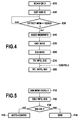
- the user U of the terminal 3 scans the QR code carried by the connected object 2 by means of its terminal 3, in a manner known per se, using a application provided for this purpose previously installed on the terminal 3 (step E10).
- the capture of the QR code by the terminal 3 triggers the download by the latter, via its communication module 3E and the mobile telecommunications network to which it is connected, the APP2 application stored on the remote server 14 (step E20).
- the APP2 application is installed for example in the nonvolatile memory 3D terminal 3. It implements all or part of the functional modules of the terminal 3 described above and is considered in the following description as an element of the terminal 3 apart whole so that one speaks indifferently in the suite of modules of the software application APP2 or modules of the terminal 3.
- the terminal 3 obtains the APP2 application and installs it on its terminal 3 to benefit from the graphic interface 15.
- the application APP2 specific to the connected object 2 further comprises an identifier IDOBJ2 associated with the connected object 2 and the configuration information required for this object.
- This identifier IDOBJ2 is used by the software application APP2 to scan the memory disks present and listed on the terminal 3 and determine if the configuration of the connected object 2 can be performed in case of detection of a disk bearing this identifier (step E30 test).
- this identifier IDOBJ2 may be contained in the QR code scanned by the user U with its terminal 3 and be used to parameterize the APP2 application.
- the launching of the configuration of the connected object 2 is not initiated automatically by the software application APP2 on the detection of a memory disk carrying the IDOBJ2 identifier but on the intervention of the user U.
- the user U connects the connected object 2 to the terminal 3 by connecting the cable 6 on both sides on both USB OTG 4 and 5 device connectors.
- the connection module 11 of the connected object 2 emulates from the terminal 3 a mass memory (step F10).
- the connected object 2 is recognized as a result of this connection to the USB device connector OTG 4 of the terminal 3 by the operating system of the terminal 3 (which acts as the detection module 7) as a mass memory (eg a USB key), that is to say as a memory disk on which it is able to write and read data via the USB OTG connection thus established via the cable 6.
- a mass memory eg a USB key
- This recognition results from the connection of the connected object 2 to the USB OTG 4 device connector of the terminal 3 and by different transactions corresponding to the USB OTG standard between the connected object 2 and the terminal 3 (ie between the slave and the master), known per se.
- the connected object 2 is declared in particular during these various transactions as a mass memory near the terminal 3.
- connection module 11 of the connected object 2 is further configured so that the mass memory thus emulated from the terminal 3 is identified by the identifier IDOBJ2.
- the detection module 7 of the terminal 3 detects the presence of a mass memory carrying the identifier IDOBJ2 stored in the APP2 application. (yes answer to the test step E30 of the figure 4 ).
- the figure 7 represents by way of example the memory disks detected by the operating system of the terminal 3 after connection of the connected object 2. Among these disks (listed in the "disk” category on the figure 7 ), appears in addition to the C: disk, a mass memory identified by IDOBJ2.
- the application APP2 is informed of this detection and triggers in response the configuration of the connected object 2 via the graphical interface 15. More specifically, it requests the user U via the graphical interface 15 so that it provides the configuration information required to configure the connected object 2.
- the terminal 3 makes the link between the newly detected mass memory (emulated by the connected object 2) and the configuration information required for the connected object. 2 thanks to IDOBJ2 ID which is carried on the one hand by the mass memory and which is stored on the other hand by APP2 application. It is this identifier IDOBJ2 that allows the APP2 application (and more specifically the association module 8) to associate the new detected mass memory or the configuration information required to configure the object 2 and which are requested to the user U via the graphical interface 15 (step E40).
- the link between the mass memory detected by the terminal 3 and the information required for the connected object 2 can be established by means of a persistent (ie non-erasable) file present in the mass memory and in which are contained information relating to the object (and in particular all or part of the configuration information to be obtained).
- the figure 6 illustrates examples of configuration information required via the graphical interface 15. According to this example, they comprise data intended to enable the connected object 2 to connect to a local network, this data comprising here a WEP key 16, a name 17, a first name 18 and the indication 19 of the presence or absence of a password to connect. It should be noted that in the example illustrated in figure 6 , other configuration information is required from the user U corresponding to the information required to allow the configuration of the functionalities implemented by the connected object (item 20 on the graphical interface 15).
- the input and validation of these various data by the user U via the input / output means 3F of the terminal 3 enable the obtaining module 9 of the APP2 application to obtain the configuration information required to configure the device. object 2 (step E50).
- configuration information can also be obtained from other entities than from the user U, for example via a communication with these entities via a local or remote network.
- the configuration information thus obtained by the terminal 3 is stored as and when they are obtained in a configuration file F stored in the nonvolatile memory 3D of the terminal.
- the APP2 application generates a digital signature GIS from the configuration information contained in the file F, in a manner known per se (step E60).
- a digital signature makes it possible, in known manner, to guarantee the integrity of electronic data and to authenticate the author thereof (namely the terminal 3 here). It can be generated according to a conventional asymmetric encryption method from a hash function and a private encryption key stored by the APP2 application, the connected object 2 having the public encryption key associated with this private key .
- the transfer module 10 writes the configuration information of the file F and the digital signature SIG on the mass memory identified by the identifier IDOBJ2 in a standard way as allowed by the USB OTG standard, that is to say as on any USB stick or remote disk that would be connected to the terminal via the device connector USB 4 OTG.
- the transfer module 10 of the terminal 3 transfers (in particular, writes) the configuration information to the connected object 2.
- the transfer of the configuration information obtained by the obtaining module 9 can be carried out in the course of the water, without prior storage in a file in the non-volatile memory 3D, but as and when of their obtaining via for example the graphical interface 15.
- the configuration information may be encrypted prior to its transfer to the connected object 2.
- Other means of proving the integrity of this information and its author may alternatively be envisaged.
- connection module 11 of the connected object coupled to the peripheral connector 5, receives the configuration information transferred by the terminal 3 via the USB OTG cable 6 and the associated digital signature GIS (step F20).
- the conformity of the digital signature SIG is then verified by the verification module 13 of the connected object 2 in a manner known per se and using the public encryption key that it has (test step F30).
- connection module 11 rejects the configuration information transmitted by the terminal 3 (step F40). For this purpose, the connection module 11 emulating a mass memory near the terminal 3 it sends to the latter a message notifying the terminal 3 of the transfer failure such as a write error message (such as the "Write Error" message) or solid memory such as those provided by the USB standard.
- a write error message such as the "Write Error” message
- solid memory such as those provided by the USB standard.
- the configuration module 14 proceeds to the configuration of the connected object 2 with the configuration information received from the terminal 3 (step F50). This step includes, for example, updating the firmware or firmware of the connected object 2 with the configuration information thus obtained.
- step E80 This step is however optional.
- the invention thus allows an (auto) configuration of the connected object 2 via any terminal and in particular a mobile terminal.
Applications Claiming Priority (1)
| Application Number | Priority Date | Filing Date | Title |
|---|---|---|---|
| FR1559102A FR3041787A1 (fr) | 2015-09-28 | 2015-09-28 | Procede de transfert d'informations de configuration d'un objet connecte |
Publications (1)
| Publication Number | Publication Date |
|---|---|
| EP3147794A1 true EP3147794A1 (de) | 2017-03-29 |
Family
ID=54545336
Family Applications (1)
| Application Number | Title | Priority Date | Filing Date |
|---|---|---|---|
| EP16188277.4A Ceased EP3147794A1 (de) | 2015-09-28 | 2016-09-12 | Transferverfahren von informationen zur konfiguration eines verbundenen objekts |
Country Status (3)
| Country | Link |
|---|---|
| US (1) | US10223296B2 (de) |
| EP (1) | EP3147794A1 (de) |
| FR (1) | FR3041787A1 (de) |
Families Citing this family (2)
| Publication number | Priority date | Publication date | Assignee | Title |
|---|---|---|---|---|
| US11055972B2 (en) * | 2017-01-16 | 2021-07-06 | Ncr Corporation | Self-service terminal (SST) network real-time cloud management |
| CN108052424A (zh) * | 2017-11-30 | 2018-05-18 | 深圳市万普拉斯科技有限公司 | Otg接口异常检测方法、装置、计算机设备和存储介质 |
Citations (2)
| Publication number | Priority date | Publication date | Assignee | Title |
|---|---|---|---|---|
| US20060035527A1 (en) * | 2004-08-11 | 2006-02-16 | Kabushiki Kaisha Toshiba | Information processing apparatus and method for controlling power supply of the apparatus |
| US20090300239A1 (en) * | 2006-04-26 | 2009-12-03 | Michael Hubo | USB Connection |
Family Cites Families (5)
| Publication number | Priority date | Publication date | Assignee | Title |
|---|---|---|---|---|
| US7546357B2 (en) * | 2004-01-07 | 2009-06-09 | Microsoft Corporation | Configuring network settings using portable storage media |
| JP5513018B2 (ja) * | 2008-06-27 | 2014-06-04 | キヤノン電子株式会社 | 周辺装置及び画像読取装置 |
| CN102004864B (zh) * | 2009-08-28 | 2013-03-13 | 台达电子工业股份有限公司 | 人机界面装置以大量储存等级实现的数据传输及防拷方法 |
| US8789146B2 (en) * | 2011-04-14 | 2014-07-22 | Yubico Inc. | Dual interface device for access control and a method therefor |
| JP5950225B2 (ja) * | 2012-01-10 | 2016-07-13 | クラリオン株式会社 | サーバ装置、車載端末、情報通信方法および情報配信システム |
-
2015
- 2015-09-28 FR FR1559102A patent/FR3041787A1/fr active Pending
-
2016
- 2016-09-12 EP EP16188277.4A patent/EP3147794A1/de not_active Ceased
- 2016-09-27 US US15/277,850 patent/US10223296B2/en active Active
Patent Citations (2)
| Publication number | Priority date | Publication date | Assignee | Title |
|---|---|---|---|---|
| US20060035527A1 (en) * | 2004-08-11 | 2006-02-16 | Kabushiki Kaisha Toshiba | Information processing apparatus and method for controlling power supply of the apparatus |
| US20090300239A1 (en) * | 2006-04-26 | 2009-12-03 | Michael Hubo | USB Connection |
Also Published As
| Publication number | Publication date |
|---|---|
| US20170091126A1 (en) | 2017-03-30 |
| US10223296B2 (en) | 2019-03-05 |
| FR3041787A1 (fr) | 2017-03-31 |
Similar Documents
| Publication | Publication Date | Title |
|---|---|---|
| US11720652B2 (en) | Monitoring a computing device to automatically obtain data in response to detecting background activity | |
| EP1987653A2 (de) | Verfahren und vorrichtung zur sicheren konfiguration eines endgeräts | |
| FR3013541A1 (fr) | Procede et dispositif pour la connexion a un service distant | |
| EP3147794A1 (de) | Transferverfahren von informationen zur konfiguration eines verbundenen objekts | |
| EP3154284A1 (de) | Kopplungsverfahren in einem peripheriegerät und einem kommunikationsendgerät, entsprechende vorrichtungen und programme | |
| FR3047583A1 (fr) | Methode de transmission securisee d'informations d'authentification entre des applications logicielles dans un terminal informatique | |
| EP3357213B1 (de) | Verfahren zum zugriff auf eine periphere vorrichtung | |
| EP3278542A1 (de) | System und verfahren zur ausführung einer anwendung auf einem mit einer chipkarte ausgestattetem endgerät | |
| US11122040B1 (en) | Systems and methods for fingerprinting devices | |
| EP2736275B1 (de) | Elektronisches Modul, das den Zugang zu einer Nachricht über ein gezieltes Betriebssystem ermöglicht | |
| CN109831588B (zh) | 一种用于设置目标提示音的方法与设备 | |
| EP3391675B1 (de) | Verfahren zur verwaltung verbindungen zwischen einem sicheren element und einem server | |
| FR2998747A1 (fr) | Procede d'aiguillage d'un message | |
| WO2022269207A1 (fr) | Procede et dispositif de controle d'acces a un support de stockage | |
| FR3110262A1 (fr) | Procédé et système d’authentification d’un utilisateur auprès d’un serveur d’authentification | |
| WO2009047438A1 (fr) | Hebergement d'applications semi-permanent | |
| FR2901386A1 (fr) | Support personnel de memoire de masse portatif et systeme informatique d'acces securise a un reseau par des utilisateurs. | |
| FR3064780A1 (fr) | Technique d'authentification d'un dispositif utilisateur | |
| FR3044134A1 (fr) | Procede et systeme de securisation de communication entre un terminal communicant et un dispositif communicant | |
| EP3110109A1 (de) | Verfahren und vorrichtung zur aktualisierung der fähigkeiten eines mit einem kommunikationsnetz verbundenen objekts | |
| FR3042362A1 (fr) | Moyens de gestion d'acces a des donnees | |
| FR3045259A1 (fr) | Procede de consultation de l'etat d'une ressource d'un appareil electronique, programme d'ordinateur et entite electronique associes et appareil electronique equipe d'une telle entite electronique | |
| FR2932582A1 (fr) | Procede et systeme de configuration simultanee d'environnement de postes clients. | |
| FR2972319A1 (fr) | Dispositif autonome de communication via une passerelle. | |
| EP2209068A1 (de) | Verfahren zur Überprüfung von Daten einer IT-Anwendung eines Endgeräts |
Legal Events
| Date | Code | Title | Description |
|---|---|---|---|
| PUAI | Public reference made under article 153(3) epc to a published international application that has entered the european phase |
Free format text: ORIGINAL CODE: 0009012 |
|
| STAA | Information on the status of an ep patent application or granted ep patent |
Free format text: STATUS: THE APPLICATION HAS BEEN PUBLISHED |
|
| AK | Designated contracting states |
Kind code of ref document: A1 Designated state(s): AL AT BE BG CH CY CZ DE DK EE ES FI FR GB GR HR HU IE IS IT LI LT LU LV MC MK MT NL NO PL PT RO RS SE SI SK SM TR |
|
| AX | Request for extension of the european patent |
Extension state: BA ME |
|
| RIN1 | Information on inventor provided before grant (corrected) |
Inventor name: BENDIABDALLAH, HALIM Inventor name: DIJOUX, GENEVIEVE |
|
| STAA | Information on the status of an ep patent application or granted ep patent |
Free format text: STATUS: REQUEST FOR EXAMINATION WAS MADE |
|
| 17P | Request for examination filed |
Effective date: 20170905 |
|
| RBV | Designated contracting states (corrected) |
Designated state(s): AL AT BE BG CH CY CZ DE DK EE ES FI FR GB GR HR HU IE IS IT LI LT LU LV MC MK MT NL NO PL PT RO RS SE SI SK SM TR |
|
| STAA | Information on the status of an ep patent application or granted ep patent |
Free format text: STATUS: EXAMINATION IS IN PROGRESS |
|
| 17Q | First examination report despatched |
Effective date: 20190516 |
|
| RAP1 | Party data changed (applicant data changed or rights of an application transferred) |
Owner name: ORANGE |
|
| STAA | Information on the status of an ep patent application or granted ep patent |
Free format text: STATUS: EXAMINATION IS IN PROGRESS |
|
| STAA | Information on the status of an ep patent application or granted ep patent |
Free format text: STATUS: EXAMINATION IS IN PROGRESS |
|
| RAP3 | Party data changed (applicant data changed or rights of an application transferred) |
Owner name: ORANGE |
|
| STAA | Information on the status of an ep patent application or granted ep patent |
Free format text: STATUS: THE APPLICATION HAS BEEN REFUSED |
|
| 18R | Application refused |
Effective date: 20221015 |