EP3147683A1 - Measuring device and measuring method for systematic error detection - Google Patents
Measuring device and measuring method for systematic error detection Download PDFInfo
- Publication number
- EP3147683A1 EP3147683A1 EP15186670.4A EP15186670A EP3147683A1 EP 3147683 A1 EP3147683 A1 EP 3147683A1 EP 15186670 A EP15186670 A EP 15186670A EP 3147683 A1 EP3147683 A1 EP 3147683A1
- Authority
- EP
- European Patent Office
- Prior art keywords
- signal
- variable
- mess
- variance
- antenna
- Prior art date
- Legal status (The legal status is an assumption and is not a legal conclusion. Google has not performed a legal analysis and makes no representation as to the accuracy of the status listed.)
- Granted
Links
- 230000009897 systematic effect Effects 0.000 title claims abstract description 54
- 238000000034 method Methods 0.000 title claims description 14
- 238000001514 detection method Methods 0.000 title 1
- 238000012545 processing Methods 0.000 claims abstract description 45
- 229920000535 Tan II Polymers 0.000 claims description 3
- 238000004891 communication Methods 0.000 claims description 3
- 238000004590 computer program Methods 0.000 claims description 2
- 238000010276 construction Methods 0.000 description 5
- 238000010586 diagram Methods 0.000 description 5
- 230000001419 dependent effect Effects 0.000 description 2
- 230000000694 effects Effects 0.000 description 2
- 230000003245 working effect Effects 0.000 description 2
- 230000003321 amplification Effects 0.000 description 1
- 230000005540 biological transmission Effects 0.000 description 1
- 238000011161 development Methods 0.000 description 1
- 230000018109 developmental process Effects 0.000 description 1
- 238000005259 measurement Methods 0.000 description 1
- 238000003199 nucleic acid amplification method Methods 0.000 description 1
- 230000001151 other effect Effects 0.000 description 1
- 239000007787 solid Substances 0.000 description 1
Images


Classifications
-
- H—ELECTRICITY
- H04—ELECTRIC COMMUNICATION TECHNIQUE
- H04W—WIRELESS COMMUNICATION NETWORKS
- H04W56/00—Synchronisation arrangements
- H04W56/0035—Synchronisation arrangements detecting errors in frequency or phase
-
- G—PHYSICS
- G01—MEASURING; TESTING
- G01R—MEASURING ELECTRIC VARIABLES; MEASURING MAGNETIC VARIABLES
- G01R29/00—Arrangements for measuring or indicating electric quantities not covered by groups G01R19/00 - G01R27/00
- G01R29/08—Measuring electromagnetic field characteristics
-
- G—PHYSICS
- G01—MEASURING; TESTING
- G01S—RADIO DIRECTION-FINDING; RADIO NAVIGATION; DETERMINING DISTANCE OR VELOCITY BY USE OF RADIO WAVES; LOCATING OR PRESENCE-DETECTING BY USE OF THE REFLECTION OR RERADIATION OF RADIO WAVES; ANALOGOUS ARRANGEMENTS USING OTHER WAVES
- G01S3/00—Direction-finders for determining the direction from which infrasonic, sonic, ultrasonic, or electromagnetic waves, or particle emission, not having a directional significance, are being received
- G01S3/02—Direction-finders for determining the direction from which infrasonic, sonic, ultrasonic, or electromagnetic waves, or particle emission, not having a directional significance, are being received using radio waves
- G01S3/023—Monitoring or calibrating
-
- H—ELECTRICITY
- H04—ELECTRIC COMMUNICATION TECHNIQUE
- H04W—WIRELESS COMMUNICATION NETWORKS
- H04W24/00—Supervisory, monitoring or testing arrangements
- H04W24/10—Scheduling measurement reports ; Arrangements for measurement reports
-
- H—ELECTRICITY
- H04—ELECTRIC COMMUNICATION TECHNIQUE
- H04W—WIRELESS COMMUNICATION NETWORKS
- H04W72/00—Local resource management
- H04W72/04—Wireless resource allocation
-
- H—ELECTRICITY
- H04—ELECTRIC COMMUNICATION TECHNIQUE
- H04W—WIRELESS COMMUNICATION NETWORKS
- H04W72/00—Local resource management
- H04W72/50—Allocation or scheduling criteria for wireless resources
- H04W72/54—Allocation or scheduling criteria for wireless resources based on quality criteria
- H04W72/541—Allocation or scheduling criteria for wireless resources based on quality criteria using the level of interference
-
- H—ELECTRICITY
- H04—ELECTRIC COMMUNICATION TECHNIQUE
- H04L—TRANSMISSION OF DIGITAL INFORMATION, e.g. TELEGRAPHIC COMMUNICATION
- H04L5/00—Arrangements affording multiple use of the transmission path
- H04L5/003—Arrangements for allocating sub-channels of the transmission path
- H04L5/0048—Allocation of pilot signals, i.e. of signals known to the receiver
- H04L5/005—Allocation of pilot signals, i.e. of signals known to the receiver of common pilots, i.e. pilots destined for multiple users or terminals
Definitions
- the invention relates to determining systematic errors in measuring signals of at least two antennas, especially in direction finding applications.
- the object of the invention is to provide a measuring device and measuring method for detecting systematic errors in measuring signals.
- An inventive measuring device comprises a processing unit, a first antenna adapted to receive a first signal, and a second antenna, adapted to receive a second signal.
- the processing unit comprises a baseline unit adapted to determine a baseline variance of a first variable and/or a second variable. Moreover, it comprises a variance unit adapted to determine a variance of the first variable and/or the second variable.
- the first variable and the second variable are each at least initially derived from at least the first signal and the second signal.
- the processing unit furthermore comprises an error unit, adapted to determine whether a systematic error is present, based on the baseline variance and the variance of the first variable and/or the second variable. It is thereby possible to determine, if a systematic error is present. Especially, in the case of direction finding applications, it is thereby possible, to determine, if a determined direction is correct or might be incorrect.
- the measuring device is adapted to measure an electromagnetic signal.
- the first antenna is then adapted to receive the electromagnetic signal as the first reception signal.
- the second antenna is then adapted to receive the electromagnetic signal as the second reception signal.
- the error unit is adapted to determine, if a systematic error is present within the electromagnetic signal. It is thereby possible to determine the presence of systematic errors within the electromagnetic signal.
- the baseline unit is adapted to determine the baseline variance of the first variable and/or the second variable while the electromagnetic signal is not present.
- the variance unit is adapted to determine the variance of the first variable and/or the second variable, while the electromagnetic signal is present. It is thereby possible to very accurately determine the baseline variance and the variance.
- the error unit is adapted to determine at least one variance quotient by dividing the variance of the first variable by the baseline variance of the first variable and/or by dividing the variance of the second variable by the baseline variance of the second variable. It is moreover adapted to compare the at least one variance quotient with at least one variance threshold. Furthermore, it is adapted to determine the presence of a systematic error, if the at least one variance quotient is above the at least one variance threshold and to determine no presence of a systematic error, if the at least one variance quotient is below the at least one variance threshold. An especially accurate and simple determining of the presence of systematic errors is thereby possible.
- the processing unit comprises a threshold unit, which is adapted to determine the at least one variance threshold based upon a power of the first signal and/or a power of the second signal and/or a number of simultaneously received signals and/or a number of determined locations of origin of received signals and/or a type of surroundings of the measuring device and/or an orientation of the measuring device and/or an availability of computational resources.
- a threshold unit which is adapted to determine the at least one variance threshold based upon a power of the first signal and/or a power of the second signal and/or a number of simultaneously received signals and/or a number of determined locations of origin of received signals and/or a type of surroundings of the measuring device and/or an orientation of the measuring device and/or an availability of computational resources.
- the first variable is a ratio of a power of a measuring point of the first signal and a power of a simultaneous measuring point of the second signal.
- the second variable then is a phase difference of a measuring point of the first signal and a simultaneous measuring point of the second signal.
- V mess,k,i is an antenna voltage of antenna k
- I mess,k,i is an inphase component of the antenna voltage of antenna k
- Q mess,k,i is a quadrature component of the antenna voltage of antenna k
- P mess,k,i is a power of the electronic signal without noise
- P noi s e is a noise power
- ⁇ ist 2 ( r mess,kl ) is the variance of the first variable
- r mess,kl is the first variable - a ratio of a reception power of the first signal and the second signal
- M is a number of the number of values of the first signal and the second signal taken into account
- i is an index of a number of values of the first signal and the second signal taken into account
- k is an index indicating the first signal
- l is an index indicating the second signal
- P k,obs,n is an observed power at antenna k
- P l,obs,n is an observed power at antenna l
- the measuring device comprises a third antenna, adapted to receive a third signal.
- the third antenna receives the electronic signal as this third signal.
- the first variable and the second variable are successively derived from the first signal and the second signal, the first signal and the third signal, and the second signal and the third signal.
- the baseline unit, the variance unit and the error unit are then adapted to perform their respective processing steps successively for the first signal and the second signal, the first signal and the third signal, and the second signal and the third signal.
- the same processing is performed three times for three different antenna pairs.
- a significant increase in accuracy of the determining of the systematic errors is thereby possible. This is especially the case, if the results of the determining of the systematic errors are OR-connected. This means that as soon as one of the error determination steps of the error unit for one of the possible antenna pairs shows a systematic error, the respective signal is considered as comprising a systematic error. Also a processing of more than three antenna pairs is possible.
- the measuring device comprises a third antenna adapted to receive a third signal.
- the first variable and the second variable can be directly derived from the first signal, the second signal and the third signal. In this case, a more complex computation is necessary, but an even more accurate determining of the systematic error is possible. Also a processing of more than three antenna signals is possible.
- the measuring device comprises a display unit, adapted to display the presence and the lack of presence of a systematic error within the electromagnetic signal.
- the measuring device comprises a communication unit, which is adapted to output information regarding the presence and the lack of presence of a systematic error within the electromagnetic signal to an external device. It is thereby possible to either display or hand on for further processing the determined information regarding the presence or lack of presence of a systematic error within the electromagnetic signal.
- the measuring device comprises a direction determining unit adapted to determine from at least the first signal and the second signal, a direction of origin of the electromagnetic signal. It is then possible to determine, if the determined direction of origin is in fact correct or might be prone to a systematic error.
- the measuring device furthermore comprises a display unit, adapted to display the direction of origin of the electromagnetic signal, preferably as a line and/or arrow pointing in the direction of the electromagnetic signal, and display the presence and the lack of presence of a systematic error within the electromagnetic signal, preferably as a color and/or shape and/or shading and/or transparency of the line and/or arrow or of a shape attached to the tip of the line and/or arrow.
- a display unit adapted to display the direction of origin of the electromagnetic signal, preferably as a line and/or arrow pointing in the direction of the electromagnetic signal, and display the presence and the lack of presence of a systematic error within the electromagnetic signal, preferably as a color and/or shape and/or shading and/or transparency of the line and/or arrow or of a shape attached to the tip of the line and/or arrow.
- the measuring device comprises a display unit, adapted to display the direction of origin of the electromagnetic signal, preferably as a line and/or arrow pointing in the direction of the electromagnetic signal, only if the error unit has determined that a systematic error is not present within the electromagnetic signal.
- the user is thereby only confronted with determined directions of origin of signals, which are not prone to systematic error. Especially in a situation with a lack of registered signals and directions of origin, this can significantly ease the user workload.
- An inventive method comprises receiving by a first antenna, a first signal and receiving by a second antenna, a second signal. Moreover, it comprises determining a baseline variance of a first variable and/or a second variable and determining a variance of the first variable and/or the second variable. The first variable and the second variable are each at least initially derived from at least the first signal and the second signal. Moreover, the method comprises determining, if a systematic error is present, based on the baseline variance and the variance of the first variable and/or the second variable. An especially simple and accurate determining of a presence of a systematic error is thereby possible.
- FIG. 1 an embodiment of the inventive measuring device 1 is shown.
- the inventive measuring device comprises an antenna unit 2 and connected to it a processing unit 3.
- An electromagnetic signal is received by the antenna unit 2 and processed by the processing unit 3.
- the processing unit 3 determines optionally the direction of origin of the electromagnetic signal and displays it.
- the processing unit 3 determines, if the electromagnetic signal received by the antenna unit 2 comprises systematic errors, for example originating from multi-path-propagation.
- Fig. 2 Regarding the construction and function of the antenna unit 2, it is referred to Fig. 2 .
- Fig. 5 and Fig. 6 Regarding the construction and function of the processing unit 3, it is referred to Fig. 5 and Fig. 6 .
- the electromagnetic signals detected by the inventive measuring device or inventive measuring method are, for example, radar pulses or radio transmissions.
- Fig. 2 shows the inner workings of the antenna unit 2 of Fig. 1 .
- the antenna unit 2 comprises an antenna array 27 comprising a plurality of antennas 20-25, which each are optionally connected to a multiplexing unit 26.
- the multiplexing unit 26 is set up for connecting a number of antennas out of the total available antennas 20-25 to the processing unit 3 of Fig. 1 .
- the number of connected antennas can be pre-specified or can be set by the processing unit 3. Especially a connection of two or three antennas is possible. Also a simultaneous connection of any other number of antennas is possible.
- antennas 20, 23 and 24 are connected by the multiplexing means 26 to the processing unit 3 of Fig. 1 .
- a receiving angle ⁇ is achieved. Within this angle, the direction of incoming electromagnetic signals can be determined. Also a determining of the presence systematic errors within received electromagnetic signals is possible within this angle.
- the multiplexing means 26 can be omitted.
- the antenna unit 2 merely comprises the antennas 20-25.
- the antenna unit 2 comprises at least two different antennas 20 - 25. Alternatively, at least five different antennas are present. Alternatively, at least ten different antennas are present.
- At least the signals of two antennas have to be used. This is also the case for determining the presence of systematic errors within the received electromagnetic signals.
- FIG. 3a an embodiment of the inventive measuring device receiving an electromagnetic signal 4 is shown.
- antennas 21, 22 of the antenna array 27 are depicted. It is clearly evident here, that antennas 21 and 22 receive the there-upon incident electromagnetic signal 4 roughly at the same time and with the same power. This can readily be seen in Fig. 3b , where the power of the signals of antenna 21 and antenna 22 are displayed over time.
- Fig. 3c the power of the respective signals of the antennas 21, 22 are shown with regard to each other. It is clearly evident that they lie very close to a line starting in the origin of the coordinate system. This means that a quotient of the powers received at antenna 21 and antenna 22 only has a very low variance.
- the electromagnetic signal 4a comprises a multi-path-propagation component 5, which arrives from a different direction of origin, since it is reflected, for example by a house. Since now the signal reaches the antennas 21, 22 at a significantly different time, and overlaps with the original line-of-sight electromagnetic signal 4, the antennas 21, 22 receive significantly different signals then shown in Fig. 3b .
- the signal P 21 , P 22 received by the respective antennas 21, 22 are shown in Fig. 4b with regard to time. Also they are shown in Fig. 4c with regard to each other. Especially there, it can clearly be seen that they no longer closely adhere to the line starting in the origin. This means that a quotient of the powers received at the antennas 21, 22 has a significantly increased variance then shown in Fig. 3c .
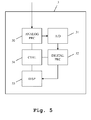
- the processing unit 3 comprises an analog processing unit 30, which is supplied with the signal of the antenna unit 2 of Fig. 1 .
- the processing unit 3 comprises an analog-digital-converter 31, which is connected to the analog processing unit 30.
- the analog-digital-converter 31, again, is connected to a digital processing unit 32, which is connected to a display unit 33.
- the analog processing unit 30, the digital processing unit 32 and the display unit 33 are connected to a control unit 34, which is set up for controlling these components.
- the measuring device 1, more accurately the processing unit 3 does not comprise a display unit 33.
- the processing unit 3 comprises a communication unit, which is adapted to hand measuring results on to an external device.
- Signals from the antenna unit 2 are received by the analog processing unit 30. These signals comprise the signals of the individual antennas 20-25 of Fig. 2 or of some of these antennas 20-25 which are currently connected to the analog processing unit 30 by use of the multiplexing unit 26. Alternatively, the signals of all antennas 20-25 of Fig. 20 can be transmitted to the analog processing unit 30 simultaneously.
- the signals received by the analog processing unit 30 are processed by it. For example, an amplification and a power determination can be performed.
- the resulting signals are handed on to the analog-digital converter 31, which digitizes the signals.
- the digitized signals are passed to the digital processing unit 32, which perform digital processing.
- the digital processing unit 32 determines, if the received electromagnetic signal comprises systematic errors. Regarding the therefore necessary processing it is referred to Fig. 6 .
- the digital processing unit 32 optionally additionally performs a determination of the direction of the detected electromagnetic signal.
- Results of the processing by the digital processing unit 32 are handed on to the display unit 33, which displays the presence of systematic errors or its lack thereof and optionally the direction of the electromagnetic signal.
- a baseline unit 321 is connected to the analog-digital-converter 31 of Fig. 5 .
- a variance unit 322 is connected to the analog-digital-converter 31 of Fig. 5 .
- the baseline unit 321 and the variance unit 322 are both connected to an error unit 324, which in turn is connected to the display unit 33 of Fig. 5 .
- a threshold unit 323 is connected to the error unit 324.
- V mess,k,i A mess , k , i exp j ⁇ mess , k , i , with
- the baseline unit 321 is adapted to determine a baseline variance of a first variable and/or a second variable.
- the first variable is a ratio of a power of a measuring point of the first signal and a power point of a simultaneous measuring point of the second signal.
- the second variable is a phase difference of a measuring point of the first signal and a simultaneous measuring point of the second signal.
- This variance is determined, while the electromagnetic signal is not received by the antennas. Therefore, only background noise is taking into consideration for determining the baseline variance of the first and/or second variable.
- a baseline variance of the first and/or second variable is determined and also a variance of the first and/or second variable of the electromagnetic signal are determined, it is possible to determine therefrom, if the electromagnetic signal suffers from systematic errors, for example originating in multi-path-propagation.
- the error unit 324 determines a quotient by dividing the variance of the first variable by the baseline variance of the first variable and/or by dividing the variance of the second variable by the baseline variance of the second variable. This variance quotient is compared to a variance threshold. In case it is above the variance threshold, it is assumed that a systematic error of the electromagnetic signal is present. In case it is below the variance threshold, it is assumed that no systematic error is present.
- the variance threshold is between 1.5 and 10. Especially, it is between 2 and 5.
- the variance threshold can be dynamically determined by the threshold unit 323.
- the threshold unit 323 determines the variance threshold dynamically based upon a number of criteria. One or more of these criteria can be used.
- the threshold unit 323 determines the variance threshold based upon a power of the first signal and/or a power of the second signal, a number of simultaneously received signals, a number of determined locations of origin of received signals, an availability of computational resources, a type of surrounding of the measuring device and/or an orientation of the measuring device.
- a high power of the first and/or second signal leads to a low variance threshold.
- a high number of determined locations of origin of received signals leads to a high variance threshold.
- An availability of computational resources leads to a high variance threshold while a lack of computational resources leads to a low variance threshold.
- a high number of determined locations of origin of received signals leads to a low variance threshold.
- the surroundings of the measuring device can also influence the variance threshold. For example, a rural environment leading to a scarce occurrence of multi-path-propagation results in a low variance threshold, while an urban environment, resulting in an often occurrence of multi-path-propagation leads to a high variance threshold.
- the orientation of the measuring device can influence the variance threshold. If the measuring device is oriented towards a direction from which the occurrence of an electromagnetic signal is probable, this leads to a high variance threshold. If it is oriented towards a direction with a low probability of the occurrence of an electromagnetic signal, this leads to a low variance threshold.
- a further embodiment of the inventive measuring device is shown.
- an exemplary content of the display device 33 is shown.
- lines 332 and 334 are depicted indicating directions of origin of electromagnetic signals.
- the tips of the lines 332 and 334 are each connected to a shape 333 and 335, which indicates, if the respective originating electromagnetic signal suffers from systematic errors or not.
- the solid shape 333 indicates that the underline electromagnetic signal does not suffer from systematic error
- the outlined shape 335 indicates that the underlined electromagnetic signal suffers from systematic errors.
- the line 334 is a dashed line, also indicating that the respective underlying electromagnetic signal has been detected to suffer from systematic error.
- a use of color and/or shape and/or shading and/or transparency of the line or an arrow or the shape attached to the tip of the line or arrow is possible.
- a background noise signal is received by at least two antennas.
- a baseline variance of a first variable and/or a second variable, especially of a power ratio and/or a phase difference of the background noise signal is determined.
- variance thresholds are determined, as explained earlier.
- an electromagnetic signal is received by the at least two antennas.
- a variance of the first and/or second variable, especially the variance of a power ratio and/or a phase difference of the electromagnetic signal is determined.
- the variances are compared to the variance threshold.
- a seventh step 106a it is determined that the electromagnetic signal does not suffer from systematic error. If at least one of the variances though is above the respective variance threshold, in an eighth step 106b, it is determined that the electromagnetic signal suffers from systematic error. In a final ninth step 107, the results are either displayed or output to an external device.
Abstract
Description
- The invention relates to determining systematic errors in measuring signals of at least two antennas, especially in direction finding applications.
- When determining the direction of origin of signals, in the ideal case, the signal travels directly from the signal source to the measuring device determining the direction of origin. This ideal case though cannot always be met in practice. In practice, multi-path-propagation and other effects, which lead to systematic errors can occur. This negatively effects the determining of the direction of origin. Significant errors in the determined direction of origin can result from the above-described effects.
- The international patent application
WO 2014/135196 A1 already shows an effective measuring device and an effective method for direction finding. This measuring device and method are, however, affected by the above-mentioned problems. - Accordingly, the object of the invention is to provide a measuring device and measuring method for detecting systematic errors in measuring signals.
- The object is solved by the features of
claim 1 for the device and claim 15 for the method. Further it is solved by the features of the claim 16 for the associated computer program. The dependent claims contain further developments. - An inventive measuring device comprises a processing unit, a first antenna adapted to receive a first signal, and a second antenna, adapted to receive a second signal. The processing unit comprises a baseline unit adapted to determine a baseline variance of a first variable and/or a second variable. Moreover, it comprises a variance unit adapted to determine a variance of the first variable and/or the second variable. The first variable and the second variable are each at least initially derived from at least the first signal and the second signal. The processing unit furthermore comprises an error unit, adapted to determine whether a systematic error is present, based on the baseline variance and the variance of the first variable and/or the second variable. It is thereby possible to determine, if a systematic error is present. Especially, in the case of direction finding applications, it is thereby possible, to determine, if a determined direction is correct or might be incorrect.
- Advantageously, the measuring device is adapted to measure an electromagnetic signal. The first antenna is then adapted to receive the electromagnetic signal as the first reception signal. The second antenna is then adapted to receive the electromagnetic signal as the second reception signal. The error unit is adapted to determine, if a systematic error is present within the electromagnetic signal. It is thereby possible to determine the presence of systematic errors within the electromagnetic signal.
- Advantageously, the baseline unit is adapted to determine the baseline variance of the first variable and/or the second variable while the electromagnetic signal is not present. In this case, the variance unit is adapted to determine the variance of the first variable and/or the second variable, while the electromagnetic signal is present. It is thereby possible to very accurately determine the baseline variance and the variance.
- Moreover advantageously, the error unit is adapted to determine at least one variance quotient by dividing the variance of the first variable by the baseline variance of the first variable and/or by dividing the variance of the second variable by the baseline variance of the second variable. It is moreover adapted to compare the at least one variance quotient with at least one variance threshold. Furthermore, it is adapted to determine the presence of a systematic error, if the at least one variance quotient is above the at least one variance threshold and to determine no presence of a systematic error, if the at least one variance quotient is below the at least one variance threshold. An especially accurate and simple determining of the presence of systematic errors is thereby possible.
- Advantageously, the processing unit comprises a threshold unit, which is adapted to determine the at least one variance threshold based upon a power of the first signal and/or a power of the second signal and/or a number of simultaneously received signals and/or a number of determined locations of origin of received signals and/or a type of surroundings of the measuring device and/or an orientation of the measuring device and/or an availability of computational resources. By dynamically determining the variance threshold, an especially accurate processing is possible.
- Further advantageously, the first variable is a ratio of a power of a measuring point of the first signal and a power of a simultaneous measuring point of the second signal. The second variable then is a phase difference of a measuring point of the first signal and a simultaneous measuring point of the second signal. By use of these variables, an especially accurate and simple determining of the presence of systematic errors is possible.
- Advantageously, the baseline unit is adapted to determine the baseline variance of the first variable as

and to determine the baseline variance of the second variable as
- σsoll 2(rmess,kl )
- is the baseline variance of the first variable,
- rmess,kl
- is the first variable - a ratio of a reception power of the first signal and the second signal,
- k
- is an index indicating the first signal,
- l
- is an index indicating the second signal,
- P noise
- is a noise power,
- Pmess,l,i
- is a power of the electronic signal without noise,
- i
- is an index of a number of values of the first signal and the second signal taken into account,
- M
- is a number of the number of values of the first signal and the second signal taken into account,
- σsoll 2(Δϕmess,kl )
- is the baseline variance of the first variable, and
- Δϕmess,kl
- is the second variable - a phase difference of the phase of the first signal and the phase of the second signal.
- An especially accurate and simple determining of the baseline variances is thereby possible.
- Further advantageously, the variance unit is adapted to determine the variance of the first variable as follows:


- Moreover, the variance unit is adapted to determine the variance of the second variable as follows:


- Especially,
Vmess,k,i is an antenna voltage of antenna k,
Imess,k,i is an inphase component of the antenna voltage of antenna k,
Qmess,k,i is a quadrature component of the antenna voltage of antenna k,
Pmess,k,i is a power of the electronic signal without noise,
P noise is a noise power,
σist 2(rmess,kl ) is the variance of the first variable,
rmess,kl is the first variable - a ratio of a reception power of the first signal and the second signal,
M is a number of the number of values of the first signal and the second signal taken into account,
i is an index of a number of values of the first signal and the second signal taken into account,
k is an index indicating the first signal,
l is an index indicating the second signal,
Pk,obs,n is an observed power at antenna k,
Pl,obs,n is an observed power at antenna l,
σist 2(Δϕmess,kl ) is the variance of the second variable,
Δϕ mess,kl is the second variable - a phase difference of the phase of the first signal and the phase of the second signal,
Ik,i is an inphase component of the antenna voltage of antenna k,
Ql,i is a quadrature component of the antenna voltage of antenna l,
Il,i is an inphase component of the antenna voltage of antenna l,
Qk,i is a quadrature component of the antenna voltage of antenna k,


- It is thereby possible, to determine the variance of the first and second variable in an especially accurate and simple manner.
- Advantageously, the measuring device comprises a third antenna, adapted to receive a third signal. Especially, the third antenna receives the electronic signal as this third signal. The first variable and the second variable are successively derived from the first signal and the second signal, the first signal and the third signal, and the second signal and the third signal. The baseline unit, the variance unit and the error unit are then adapted to perform their respective processing steps successively for the first signal and the second signal, the first signal and the third signal, and the second signal and the third signal. Thereby, the same processing is performed three times for three different antenna pairs. A significant increase in accuracy of the determining of the systematic errors is thereby possible. This is especially the case, if the results of the determining of the systematic errors are OR-connected. This means that as soon as one of the error determination steps of the error unit for one of the possible antenna pairs shows a systematic error, the respective signal is considered as comprising a systematic error. Also a processing of more than three antenna pairs is possible.
- Alternatively, the measuring device comprises a third antenna adapted to receive a third signal. The first variable and the second variable can be directly derived from the first signal, the second signal and the third signal. In this case, a more complex computation is necessary, but an even more accurate determining of the systematic error is possible. Also a processing of more than three antenna signals is possible.
- Advantageously, the measuring device comprises a display unit, adapted to display the presence and the lack of presence of a systematic error within the electromagnetic signal. Alternatively or additionally, the measuring device comprises a communication unit, which is adapted to output information regarding the presence and the lack of presence of a systematic error within the electromagnetic signal to an external device. It is thereby possible to either display or hand on for further processing the determined information regarding the presence or lack of presence of a systematic error within the electromagnetic signal.
- Advantageously, the measuring device comprises a direction determining unit adapted to determine from at least the first signal and the second signal, a direction of origin of the electromagnetic signal. It is then possible to determine, if the determined direction of origin is in fact correct or might be prone to a systematic error.
- Advantageously, the measuring device furthermore comprises a display unit, adapted to display the direction of origin of the electromagnetic signal, preferably as a line and/or arrow pointing in the direction of the electromagnetic signal, and display the presence and the lack of presence of a systematic error within the electromagnetic signal, preferably as a color and/or shape and/or shading and/or transparency of the line and/or arrow or of a shape attached to the tip of the line and/or arrow. A user thereby can very easily determine, if a determined direction of origin of an electromagnetic signal is prone to systematic error or not.
- Further advantageously, the measuring device comprises a display unit, adapted to display the direction of origin of the electromagnetic signal, preferably as a line and/or arrow pointing in the direction of the electromagnetic signal, only if the error unit has determined that a systematic error is not present within the electromagnetic signal. The user is thereby only confronted with determined directions of origin of signals, which are not prone to systematic error. Especially in a situation with a lack of registered signals and directions of origin, this can significantly ease the user workload.
- An inventive method comprises receiving by a first antenna, a first signal and receiving by a second antenna, a second signal. Moreover, it comprises determining a baseline variance of a first variable and/or a second variable and determining a variance of the first variable and/or the second variable. The first variable and the second variable are each at least initially derived from at least the first signal and the second signal. Moreover, the method comprises determining, if a systematic error is present, based on the baseline variance and the variance of the first variable and/or the second variable. An especially simple and accurate determining of a presence of a systematic error is thereby possible.
- An exemplary embodiment of the invention is now further explained by way of example only with respect to the drawings, in which
- Fig. 1
- shows an embodiment of the inventive measuring device in an overview block diagram;
- Fig. 2
- shows a block diagram of a detail of an embodiment of the inventive measuring device;
- Fig. 3a
- shows an embodiment of the inventive measuring device receiving an electromagnetic signal;
- Fig. 3b
- shows power levels received by antennas of the embodiment of the inventive device over time;
- Fig. 3c
- shows power levels of antennas of the embodiment of the inventive device with regard to each other;
- Fig. 4a
- shows an embodiment of the inventive measuring device receiving an electromagnetic signal comprising a multi-path error component;
- Fig. 4b
- shows power levels of signals received by antennas of the fourth embodiment over time;
- Fig. 4c
- shows power levels of antennas of an embodiment of the inventive measuring device with regard to each other;
- Fig. 5
- shows a block diagram of a detail of an embodiment of the inventive measuring device;
- Fig. 6
- shows block diagram of a detail of an embodiment of the inventive measuring device;
- Fig. 7
- shows display content of another embodiment of the inventive measuring device, and
- Fig. 8
- shows an exemplary embodiment of the inventive measuring method in a flow diagram.
- First we demonstrate the general construction of embodiments of the inventive measuring device along
Fig. 1 - 2 . AlongFig. 3a, 3b, 3c ,4a, 4b and 4c , the problem underlying the present invention and the function of different embodiments of the inventive measuring device and method are discussed in detail. AlongFig. 5 andFig. 6 , the detailed construction of embodiments of the inventive measuring device and their respective functions are described. AlongFig. 7 , possible ways of displaying measuring results are discussed. Finally, with regard toFig. 8 , an embodiment of the inventive measuring method is discussed in detail. Similar entities and reference numbers in different figures have been partially omitted. - In
Fig. 1 , an embodiment of theinventive measuring device 1 is shown. The inventive measuring device comprises anantenna unit 2 and connected to it aprocessing unit 3. An electromagnetic signal is received by theantenna unit 2 and processed by theprocessing unit 3. Theprocessing unit 3 determines optionally the direction of origin of the electromagnetic signal and displays it. - Moreover, the
processing unit 3 determines, if the electromagnetic signal received by theantenna unit 2 comprises systematic errors, for example originating from multi-path-propagation. - Regarding the construction and function of the
antenna unit 2, it is referred toFig. 2 . Regarding the construction and function of theprocessing unit 3, it is referred toFig. 5 andFig. 6 . - The electromagnetic signals detected by the inventive measuring device or inventive measuring method are, for example, radar pulses or radio transmissions.
-
Fig. 2 shows the inner workings of theantenna unit 2 ofFig. 1 . Theantenna unit 2 comprises anantenna array 27 comprising a plurality of antennas 20-25, which each are optionally connected to amultiplexing unit 26. The multiplexingunit 26 is set up for connecting a number of antennas out of the total available antennas 20-25 to theprocessing unit 3 ofFig. 1 . The number of connected antennas can be pre-specified or can be set by theprocessing unit 3. Especially a connection of two or three antennas is possible. Also a simultaneous connection of any other number of antennas is possible. - For example,
antennas processing unit 3 ofFig. 1 . In this case, a receiving angle γ is achieved. Within this angle, the direction of incoming electromagnetic signals can be determined. Also a determining of the presence systematic errors within received electromagnetic signals is possible within this angle. - In an alternative embodiment, the multiplexing means 26 can be omitted. In this case, the
antenna unit 2 merely comprises the antennas 20-25. - The
antenna unit 2 comprises at least two different antennas 20 - 25. Alternatively, at least five different antennas are present. Alternatively, at least ten different antennas are present. - For being able to detect a direction of an incoming signal, at least the signals of two antennas have to be used. This is also the case for determining the presence of systematic errors within the received electromagnetic signals.
- In
Fig. 3a , an embodiment of the inventive measuring device receiving anelectromagnetic signal 4 is shown. Here, onlyantennas antenna array 27 are depicted. It is clearly evident here, thatantennas electromagnetic signal 4 roughly at the same time and with the same power. This can readily be seen inFig. 3b , where the power of the signals ofantenna 21 andantenna 22 are displayed over time. - In
Fig. 3c , the power of the respective signals of theantennas antenna 21 andantenna 22 only has a very low variance. - In
Fig. 4a , a further embodiment of the inventive measuring device receiving anelectromagnetic signal 4a is shown. Here, theelectromagnetic signal 4a comprises a multi-path-propagation component 5, which arrives from a different direction of origin, since it is reflected, for example by a house. Since now the signal reaches theantennas electromagnetic signal 4, theantennas Fig. 3b . The signal P21, P22 received by therespective antennas Fig. 4b with regard to time. Also they are shown inFig. 4c with regard to each other. Especially there, it can clearly be seen that they no longer closely adhere to the line starting in the origin. This means that a quotient of the powers received at theantennas Fig. 3c . - In
Fig. 5 , the internal construction of theprocessing unit 3 ofFig. 1 is shown. Theprocessing unit 3 comprises ananalog processing unit 30, which is supplied with the signal of theantenna unit 2 ofFig. 1 . Moreover, theprocessing unit 3 comprises an analog-digital-converter 31, which is connected to theanalog processing unit 30. The analog-digital-converter 31, again, is connected to adigital processing unit 32, which is connected to adisplay unit 33. Theanalog processing unit 30, thedigital processing unit 32 and thedisplay unit 33 are connected to acontrol unit 34, which is set up for controlling these components. - Alternatively, the measuring
device 1, more accurately theprocessing unit 3 does not comprise adisplay unit 33. In this case, it comprises a communication unit, which is adapted to hand measuring results on to an external device. - Signals from the
antenna unit 2 are received by theanalog processing unit 30. These signals comprise the signals of the individual antennas 20-25 ofFig. 2 or of some of these antennas 20-25 which are currently connected to theanalog processing unit 30 by use of the multiplexingunit 26. Alternatively, the signals of all antennas 20-25 of Fig. 20 can be transmitted to theanalog processing unit 30 simultaneously. - The signals received by the
analog processing unit 30 are processed by it. For example, an amplification and a power determination can be performed. The resulting signals are handed on to the analog-digital converter 31, which digitizes the signals. The digitized signals are passed to thedigital processing unit 32, which perform digital processing. - The
digital processing unit 32 determines, if the received electromagnetic signal comprises systematic errors. Regarding the therefore necessary processing it is referred toFig. 6 . - The
digital processing unit 32 optionally additionally performs a determination of the direction of the detected electromagnetic signal. - Results of the processing by the
digital processing unit 32 are handed on to thedisplay unit 33, which displays the presence of systematic errors or its lack thereof and optionally the direction of the electromagnetic signal. - Regarding the inner workings of the
digital processing unit 32, it is referred toFig. 6 . Abaseline unit 321 is connected to the analog-digital-converter 31 ofFig. 5 . Also, avariance unit 322 is connected to the analog-digital-converter 31 ofFig. 5 . Thebaseline unit 321 and thevariance unit 322 are both connected to anerror unit 324, which in turn is connected to thedisplay unit 33 ofFig. 5 . Optionally, athreshold unit 323 is connected to theerror unit 324. - In an exemplary measuring device, a digital measuring voltage Vmess,k,i is received:

with - k=1...N
- Amess,k,i
- being a measuring amplitude,
- Φmess,k,i
- being a measuring phase,
- k
- being an antenna number index,
- i
- being a measuring value index, and
- N
- being a total number of measurements.
- A first variable rmess,kl,i and a second variable ΔΦmess,kl,i are determined:


with - rmess,kl,i
- being a quotient between a measuring amplitude of antenna k and
antenna 1, - ΔΦmess,kl,i
- being a phase difference between a measuring amplitude of antenna k, and
antenna 1 - k
- being an antenna number index,
- l
- being an antenna number index, and
- i
- being a measuring value index.
- A variance of the first variable is then determined as:

with - σ2(rmess,kl)
- being the first variable,
- M
- being a total number of considered measuring values,
- i
- being a measuring value index, and
- rmess,kl,i
- being a quotient between a measuring amplitude of antenna k and antenna l.
- A variance of the second variable is determined as:

with - σ2 (Φmess,kl)
- being the second variable,
- M
- being a total number of considered measuring values,
- i
- being a measuring value index, and
- Φmess,kl,i
- being a phase difference between antenna k and antenna l.
- Primarily considering the measuring error, it is though not possible to determine, if the electromagnetic signal suffers from systematic error, for example originating in multi-path-propagation.
- Therefore, in the embodiments of the present invention, the
baseline unit 321 is adapted to determine a baseline variance of a first variable and/or a second variable. The first variable is a ratio of a power of a measuring point of the first signal and a power point of a simultaneous measuring point of the second signal. The second variable is a phase difference of a measuring point of the first signal and a simultaneous measuring point of the second signal. The baseline variance is determined as follows:

with - σsoll 2(rmess,kl )
- being the baseline variance of the first variable,
- r mess,kl
- being the first variable - a ratio of a reception power of the first signal and the second signal,
- k
- being an index indicating the first signal,
- l
- being an index indicating the second signal,
- P noise
- being a noise power,
- P mess,l,i
- being a power of the electronic signal without noise,
- i
- being an index of a number of values of the first signal and the second signal taken into account,
- M
- being a number of the number of values of the first signal and the second signal taken into account,
- σsoll 2(Δϕmess,kl )
- being the baseline variance of the first variable, and
- Δϕ mess,kl
- being the second variable - a phase difference of the phase of the first signal and the phase of the second signal.
- This variance is determined, while the electromagnetic signal is not received by the antennas. Therefore, only background noise is taking into consideration for determining the baseline variance of the first and/or second variable.
- As soon as the electromagnetic signal is received, the
variance unit 322 determines the variance of the first and second variable of the electromagnetic signal. This is done as follows:


with

with


with
V mess,k,i being an antenna voltage of antenna k,
I mess,k,i being an inphase component of the antenna voltage of antenna k,
Q mess,k,i being a quadrature component of the antenna voltage of antenna k,
P mess,k,i being a power of the electronic signal without noise,
P noise being a noise power,
σist 2(rmess,kl ) being the variance of the first variable,
r mess,kl being the first variable - a ratio of a reception power of the first signal and the second signal,
M being a number of the number of values of the first signal and the second signal taken into account,
i being an index of a number of values of the first signal and the second signal taken into account,
k being an index indicating the first signal,
l being an index indicating the second signal,
P k,obs,n being an observed power at antenna k,
P l,obs,n being an observed power at antenna l,
σist 2(Δϕmess,kl ) being the variance of the second variable,
Δϕ mess,kl being the second variable - a phase difference of the phase of the first signal and the phase of the second signal,
I k,i being an inphase component of the antenna voltage of antenna k,
Q l,i being a quadrature component of the antenna voltage of antenna l,
I l,i being an inphase component of the antenna voltage of antenna l,
Q k,i being a quadrature component of the antenna voltage of antenna k,


- It is especially important to note that the above-shown implementation is especially suitable to be implemented into a FPGA or multi-purpose processor, since it avoids divisions to a large degree.
- Now that a baseline variance of the first and/or second variable is determined and also a variance of the first and/or second variable of the electromagnetic signal are determined, it is possible to determine therefrom, if the electromagnetic signal suffers from systematic errors, for example originating in multi-path-propagation.
- This is done by the
error unit 324, which is supplied with the baseline variances by thebaseline unit 321 and the variances by thevariance unit 322. Theerror unit 324 determines a quotient by dividing the variance of the first variable by the baseline variance of the first variable and/or by dividing the variance of the second variable by the baseline variance of the second variable. This variance quotient is compared to a variance threshold. In case it is above the variance threshold, it is assumed that a systematic error of the electromagnetic signal is present. In case it is below the variance threshold, it is assumed that no systematic error is present. The variance threshold is between 1.5 and 10. Especially, it is between 2 and 5. - Optionally, the variance threshold can be dynamically determined by the
threshold unit 323. Thethreshold unit 323 determines the variance threshold dynamically based upon a number of criteria. One or more of these criteria can be used. Thethreshold unit 323 determines the variance threshold based upon a power of the first signal and/or a power of the second signal, a number of simultaneously received signals, a number of determined locations of origin of received signals, an availability of computational resources, a type of surrounding of the measuring device and/or an orientation of the measuring device. - Especially, a high power of the first and/or second signal leads to a low variance threshold. A high number of determined locations of origin of received signals leads to a high variance threshold. An availability of computational resources leads to a high variance threshold while a lack of computational resources leads to a low variance threshold. A high number of determined locations of origin of received signals leads to a low variance threshold.
- The surroundings of the measuring device can also influence the variance threshold. For example, a rural environment leading to a scarce occurrence of multi-path-propagation results in a low variance threshold, while an urban environment, resulting in an often occurrence of multi-path-propagation leads to a high variance threshold.
- Also the orientation of the measuring device can influence the variance threshold. If the measuring device is oriented towards a direction from which the occurrence of an electromagnetic signal is probable, this leads to a high variance threshold. If it is oriented towards a direction with a low probability of the occurrence of an electromagnetic signal, this leads to a low variance threshold.
- In
Fig. 7 , a further embodiment of the inventive measuring device is shown. Here, an exemplary content of thedisplay device 33 is shown. Within acircle 331,lines lines shape solid shape 333 indicates that the underline electromagnetic signal does not suffer from systematic error, while the outlinedshape 335 indicates that the underlined electromagnetic signal suffers from systematic errors. Also, theline 334 is a dashed line, also indicating that the respective underlying electromagnetic signal has been detected to suffer from systematic error. Besides the here-depicted options of indicating systematic error, also a use of color and/or shape and/or shading and/or transparency of the line or an arrow or the shape attached to the tip of the line or arrow is possible. - Finally, in
Fig. 8 , an embodiment of the inventive measuring method is shown. In afirst step 100, a background noise signal is received by at least two antennas. In asecond step 101, a baseline variance of a first variable and/or a second variable, especially of a power ratio and/or a phase difference of the background noise signal is determined. In an optionalthird step 102, variance thresholds are determined, as explained earlier. In afourth step 103, an electromagnetic signal is received by the at least two antennas. In afifth step 104, a variance of the first and/or second variable, especially the variance of a power ratio and/or a phase difference of the electromagnetic signal is determined. In asixth step 105, the variances are compared to the variance threshold. If none of the variances is above the variance threshold, in aseventh step 106a, it is determined that the electromagnetic signal does not suffer from systematic error. If at least one of the variances though is above the respective variance threshold, in aneighth step 106b, it is determined that the electromagnetic signal suffers from systematic error. In a finalninth step 107, the results are either displayed or output to an external device. - The invention is not limited to the examples. The characteristics of the exemplary embodiments can be used in any advantageous combination. All features claimed in the claims and/or described in the description and/or drawn in the drawings can be combined. Especially, all features of the dependent device claims can also be combined with the independent method claim.
Claims (16)
- Measuring device, comprising a processing unit (32), a first antenna (21), adapted to receive a first signal, and a second antenna (22), adapted to receive a second signal,
characterized in that
the processing unit (32) comprises:- a baseline unit (321) adapted to determine a baseline variance of a first variable and/or a second variable,- a variance unit (322) adapted to determine a variance of the first variable and/or the second variable, wherein the first variable and the second variable are each at least initially derived from at least the first signal and the second signal, and- an error unit (324), adapted to determine whether a systematic error is present, based on the baseline variance and the variance of the first variable and/or the second variable. - Measuring device according to claim 1,
characterized in that
the measuring device (1) is adapted to measure an electromagnetic signal (4a),
the first antenna (21) is adapted to receive the electromagnetic signal (4a) as the first reception signal, the second antenna (22) is adapted to receive the electromagnetic signal (4a) as the second reception signal, and
the error unit (324) is adapted to determine whether a systematic error is present within the electromagnetic signal (4a). - Measuring device according to claim 2,
characterized in that
the baseline unit (321) is adapted to determine the baseline variance of the first variable and/or the second variable, while the electromagnetic signal (4a) is not present, and
the variance unit (322) is adapted to determine the variance of the first variable and/or the second variable, while the electromagnetic signal (4a) is present. - Measuring device according to claims 2 or 3,
characterized in that
the error unit (324) is adapted to:- determine at least one variance quotient by dividing the variance of the first variable by the baseline variance of the first variable, and/or by dividing the variance of the second variable by the baseline variance of the second variable,- compare the at least one variance quotient with at least one variance threshold,- determine the presence of a systematic error, if the at least one variance quotient is above the at least one variance threshold, and- determine no presence of a systematic error, if the at least one variance quotient is below the at least one variance threshold. - Measuring device according to claim 4,
characterized in that
the processing unit (32) comprises a threshold unit (323), adapted to determine the at least one variance threshold, based upon:- a power of the first signal and/or a power of the second signal, and/or- a number of simultaneously received signals, and/or- a number of determined locations of origin of received signals and/or- an availability of computational resources, and/or- a type of surrounding of the measuring device, and/or- an orientation of the measuring device. - Measuring device according to any of the claims 2 to 5,
characterized in that
the first variable is a ratio of a power of a measuring point of the first signal and a power of a simultaneous measuring point of the second signal, and/or
the second variable is a phase difference of a measuring point of the first signal and a simultaneous measuring point of the second signal. - Measuring device according to claim 6,
characterized in that
wherein the baseline unit (321) is adapted to- determine the baseline variance of the first variable as
and/or- determine the baseline variance of the second variable aswherein σsoll 2(rmess,kl ) is the baseline variance of the first variable,rmess,kl is the first variable - a ratio of a reception power of the first signal and the second signal,k is an index indicating the first signal,l is an index indicating the second signal,P noise is a noise power,P mess,l,i is a power of the electronic signal without noise,i is an index of a number of values of the first signal and the second signal taken into account,M is a number of the number of values of the first signal and the second signal taken into account,σsoll 2(Δϕmess,kl ) is the baseline variance of the first variable, andΔϕmess,kl is the second variable - a phase difference of the phase of the first signal and the phase of the second signal.
 - Measuring device according to claim 6 or 7,
characterized in that
wherein the variance unit (322) is adapted to- determine the variance of the first variable as follows:


with
and/or- determine the variance of the second variable as follows:


with


whereinV mess,k,i is an antenna voltage of antenna k,I mess,k,i is an inphase component of the antenna voltage of antenna k,Q mess,k,i is a quadrature component of the antenna voltage of antenna k,P mess,k,i is a power of the electronic signal without noise,P noise is a noise power,σist 2(rmess,kl ) is the variance of the first variable,r mess,kl is the first variable - a ratio of a reception power of the first signal and the second signal,M is a number of the number of values of the first signal and the second signal taken into account,i is an index of a number of values of the first signal and the second signal taken into account,k is an index indicating the first signal,l is an index indicating the second signal,P k,obs,n is an observed power at antenna k,P l,obs,n is an observed power at antenna l,σist 2(Δϕmess,kl ) is the variance of the second variable,Δϕ mess,kl is the second variable - a phase difference of the phase of the first signal and the phase of the second signal,I k,i is an inphase component of the antenna voltage of antenna k,Q l,i is a quadrature component of the antenna voltage of antenna l,I l,i is an inphase component of the antenna voltage of antenna l,Q k,i is a quadrature component of the antenna voltage of antenna k,

- Measuring device according to any of the claims 2 to 8,
characterized in that
the measuring device (1) comprises a third antenna, adapted to receive a third signal,
the first variable and the second variable are successively derived from- the first signal and the second signal,- the first signal and the third signal, and- the second signal and the third signal, the baseline unit (321) is adapted to determine the baseline variance, successively for the first variable and the second variable being successively derived from- the first signal and the second signal,- the first signal and the third signal, and- the second signal and the third signal, the variance unit (322) is adapted to determine the variance of the first variable and/or the second variable, successively for the first variable and the second variable being successively derived from- the first signal and the second signal,- the first signal and the third signal, and- the second signal and the third signal, and the error unit (324) is adapted to determine if a systematic error is present, successively based on the baseline variance and the variance of the first variable and/or the second variable being successively derived from- the first signal and the second signal,- the first signal and the third signal, and- the second signal and the third signal. - Measuring device according to any of the claims 2 to 8,
characterized in that
the measuring device comprises a third antenna, adapted to receive a third signal,
the first variable and the second variable are derived from the first signal, the second signal and
the third signal. - Measuring device according to any of the claims 2 to 10,
characterized in that
the measuring device (1) comprises a display unit (33), adapted to display the presence and the lack of presence of a systematic error within the electromagnetic signal (4a), and/or
the measuring device (1) comprises a communication unit, adapted to output information regarding the presence and
the lack of presence of a systematic error within the electromagnetic signal (4a) to an external device. - Measuring device according to any of the claims 2 to 11,
characterized in that
the measuring device (1) comprises a direction determining unit, adapted to determine from at least the first signal and the second signal, a direction of origin of the electromagnetic signal (4a). - Measuring device according to claim 12,
characterized in that
the measuring device (1) comprises a display unit (33), adapted to- display the direction of origin of the electromagnetic signal (4a), preferably as line (332, 334) and/or arrow pointing in the direction of the electromagnetic signal (4a), and- display the presence and the lack of presence of a systematic error within the electromagnetic signal (4a), preferably as a color and/or shape and/or shading and/or transparency of the line and/or arrow or of a shape (333, 335) attached to a tip of the line and/or arrow. - Measuring device according to claim 13,
characterized in that
the measuring device (1) comprises a display unit (33), adapted to display the direction of origin of the electromagnetic signal (4a), preferably as line (332) and/or arrow pointing in the direction of the electromagnetic signal (4a), only if the error unit (324) has determined that a systematic error is not present within the electromagnetic signal (4a). - A method comprising the following steps:- receiving (100), by a first antenna (21), a first signal,- receiving (100), by a second antenna, a second signal,- determining (101) a baseline variance of a first variable and/or a second variable,- determining (104) a variance of the first variable and/or the second variable, wherein the first variable and the second variable are each at least initially derived from at least the first signal and the second signal, and- determining (105) whether a systematic error is present, based on the baseline variance and the variance of the first variable and/or the second variable.
- A computer program with program code means for performing all steps according to claim 15 if the program is executed on a computer or a digital signal processor.
Priority Applications (3)
| Application Number | Priority Date | Filing Date | Title |
|---|---|---|---|
| EP15186670.4A EP3147683B8 (en) | 2015-09-24 | 2015-09-24 | Measuring device and measuring method for systematic error detection |
| CN201610721405.3A CN106556749B (en) | 2015-09-24 | 2016-08-24 | Measuring device and measuring method for system error detection |
| US15/246,482 US10278149B2 (en) | 2015-09-24 | 2016-08-24 | Measuring device and measuring method for systematic error detection |
Applications Claiming Priority (1)
| Application Number | Priority Date | Filing Date | Title |
|---|---|---|---|
| EP15186670.4A EP3147683B8 (en) | 2015-09-24 | 2015-09-24 | Measuring device and measuring method for systematic error detection |
Publications (3)
| Publication Number | Publication Date |
|---|---|
| EP3147683A1 true EP3147683A1 (en) | 2017-03-29 |
| EP3147683B1 EP3147683B1 (en) | 2020-06-17 |
| EP3147683B8 EP3147683B8 (en) | 2020-08-12 |
Family
ID=54199588
Family Applications (1)
| Application Number | Title | Priority Date | Filing Date |
|---|---|---|---|
| EP15186670.4A Active EP3147683B8 (en) | 2015-09-24 | 2015-09-24 | Measuring device and measuring method for systematic error detection |
Country Status (3)
| Country | Link |
|---|---|
| US (1) | US10278149B2 (en) |
| EP (1) | EP3147683B8 (en) |
| CN (1) | CN106556749B (en) |
Families Citing this family (2)
| Publication number | Priority date | Publication date | Assignee | Title |
|---|---|---|---|---|
| CN112558189B (en) * | 2020-11-27 | 2023-03-03 | 上海欧菲智能车联科技有限公司 | Rainfall detection method, rainfall detection device, vehicle and readable storage medium |
| US11828801B2 (en) * | 2022-03-28 | 2023-11-28 | Rohde & Schwarz Gmbh & Co. Kg | System and method of over-the-air testing of a device under test |
Citations (3)
| Publication number | Priority date | Publication date | Assignee | Title |
|---|---|---|---|---|
| US5457466A (en) * | 1993-09-07 | 1995-10-10 | Litton Systems Inc. | Emitter azimuth and elevation direction finding using only linear interferometer arrays |
| US5526001A (en) * | 1992-12-11 | 1996-06-11 | Litton Systems Inc. | Precise bearings only geolocation in systems with large measurements bias errors |
| WO2014135196A1 (en) | 2013-03-05 | 2014-09-12 | Rohde & Schwarz Gmbh & Co. Kg | Measuring device and measuring method for direction finding and direction uncertainty determination |
Family Cites Families (7)
| Publication number | Priority date | Publication date | Assignee | Title |
|---|---|---|---|---|
| US7099469B2 (en) * | 2001-10-17 | 2006-08-29 | Motorola, Inc. | Method of scrambling and descrambling data in a communication system |
| US7983367B2 (en) * | 2007-01-09 | 2011-07-19 | Broadcom Corporation | Method and system for dynamic adaptation and communicating differences in frequency—time dependent systems |
| EP2135368A4 (en) * | 2007-03-15 | 2016-04-13 | Compass Auto Tracker Llc | An apparatus and method for a directional finder |
| US7626889B2 (en) * | 2007-04-06 | 2009-12-01 | Microsoft Corporation | Sensor array post-filter for tracking spatial distributions of signals and noise |
| US8121225B1 (en) * | 2008-06-24 | 2012-02-21 | L-3 Services, Inc. | Estimating the angle of arrival of a signal received by an array of commutated antenna elements |
| US20110267225A1 (en) * | 2010-04-28 | 2011-11-03 | Liwen Dai | System and method for determining the heading angle of a vehicle |
| KR102367213B1 (en) * | 2015-02-13 | 2022-02-25 | 삼성전자주식회사 | Device for Performing Communication by Selectively Using Multiple Antennas and Method thereof |
-
2015
- 2015-09-24 EP EP15186670.4A patent/EP3147683B8/en active Active
-
2016
- 2016-08-24 US US15/246,482 patent/US10278149B2/en active Active
- 2016-08-24 CN CN201610721405.3A patent/CN106556749B/en active Active
Patent Citations (3)
| Publication number | Priority date | Publication date | Assignee | Title |
|---|---|---|---|---|
| US5526001A (en) * | 1992-12-11 | 1996-06-11 | Litton Systems Inc. | Precise bearings only geolocation in systems with large measurements bias errors |
| US5457466A (en) * | 1993-09-07 | 1995-10-10 | Litton Systems Inc. | Emitter azimuth and elevation direction finding using only linear interferometer arrays |
| WO2014135196A1 (en) | 2013-03-05 | 2014-09-12 | Rohde & Schwarz Gmbh & Co. Kg | Measuring device and measuring method for direction finding and direction uncertainty determination |
Also Published As
| Publication number | Publication date |
|---|---|
| CN106556749B (en) | 2020-12-04 |
| EP3147683B1 (en) | 2020-06-17 |
| CN106556749A (en) | 2017-04-05 |
| US10278149B2 (en) | 2019-04-30 |
| EP3147683B8 (en) | 2020-08-12 |
| US20170094626A1 (en) | 2017-03-30 |
Similar Documents
| Publication | Publication Date | Title |
|---|---|---|
| US10962637B2 (en) | Radar data processing using neural network classifier and confidence metrics | |
| CN104345303A (en) | Radar calibration system for vehicles | |
| JP2008134223A (en) | Target detection method of radar, and radar system using this target detection method | |
| EP2224261A3 (en) | Detection and resolution of closely spaced targets in a monopulse system | |
| CN111665482B (en) | Target resolution method based on digital beam forming, storage medium and electronic equipment | |
| US20140347168A1 (en) | Rfid tag distance measurer | |
| EP2426508A3 (en) | Target detection system, detection method, and detection information processing program | |
| EP3147683B1 (en) | Measuring device and measuring method for systematic error detection | |
| US9684065B2 (en) | Method and device for detecting structures in an object under investigation | |
| EP2965108B1 (en) | Measuring device and measuring method for direction finding and direction uncertainty determination | |
| EP3208620A1 (en) | Measuring system for over-the-air power measurements | |
| JPWO2020039797A1 (en) | Echo data processing device, radar device, echo data processing method, and echo data processing program | |
| CN102185669B (en) | Method and device for determining state of antenna feed system | |
| JP2015099097A (en) | Synthetic aperture radar device and image processing method thereof | |
| EP3816670A1 (en) | Meteorological radar device, meteorological observation method, and meteorological observation program | |
| JP3405299B2 (en) | Radar target determination method and radar apparatus | |
| RU2421749C1 (en) | Direction finder | |
| JP2013024775A (en) | Radar device | |
| US20140077999A1 (en) | Method and apparatus for detecting locations of multiple radio sources | |
| US10718848B2 (en) | Method and device for direction finding with direction evaluation | |
| CN109188351A (en) | A kind of wirelessly anti-interference localization method and device | |
| RU2256933C1 (en) | Angular selector for surveillance pulse radar | |
| JP2021124311A (en) | Interference removal device and interference removal program | |
| RU2255348C1 (en) | Device for estimation of target co-ordinates for monopulse radars | |
| CN116430343A (en) | Deformation monitoring radar scattering point selection method and device and processing equipment |
Legal Events
| Date | Code | Title | Description |
|---|---|---|---|
| PUAI | Public reference made under article 153(3) epc to a published international application that has entered the european phase |
Free format text: ORIGINAL CODE: 0009012 |
|
| STAA | Information on the status of an ep patent application or granted ep patent |
Free format text: STATUS: REQUEST FOR EXAMINATION WAS MADE |
|
| 17P | Request for examination filed |
Effective date: 20160512 |
|
| AK | Designated contracting states |
Kind code of ref document: A1 Designated state(s): AL AT BE BG CH CY CZ DE DK EE ES FI FR GB GR HR HU IE IS IT LI LT LU LV MC MK MT NL NO PL PT RO RS SE SI SK SM TR |
|
| AX | Request for extension of the european patent |
Extension state: BA ME |
|
| STAA | Information on the status of an ep patent application or granted ep patent |
Free format text: STATUS: EXAMINATION IS IN PROGRESS |
|
| 17Q | First examination report despatched |
Effective date: 20190109 |
|
| GRAP | Despatch of communication of intention to grant a patent |
Free format text: ORIGINAL CODE: EPIDOSNIGR1 |
|
| STAA | Information on the status of an ep patent application or granted ep patent |
Free format text: STATUS: GRANT OF PATENT IS INTENDED |
|
| INTG | Intention to grant announced |
Effective date: 20190719 |
|
| RIN1 | Information on inventor provided before grant (corrected) |
Inventor name: BARTKO, HENDRIK |
|
| GRAJ | Information related to disapproval of communication of intention to grant by the applicant or resumption of examination proceedings by the epo deleted |
Free format text: ORIGINAL CODE: EPIDOSDIGR1 |
|
| STAA | Information on the status of an ep patent application or granted ep patent |
Free format text: STATUS: EXAMINATION IS IN PROGRESS |
|
| INTC | Intention to grant announced (deleted) | ||
| GRAJ | Information related to disapproval of communication of intention to grant by the applicant or resumption of examination proceedings by the epo deleted |
Free format text: ORIGINAL CODE: EPIDOSDIGR1 |
|
| GRAP | Despatch of communication of intention to grant a patent |
Free format text: ORIGINAL CODE: EPIDOSNIGR1 |
|
| GRAS | Grant fee paid |
Free format text: ORIGINAL CODE: EPIDOSNIGR3 |
|
| GRAS | Grant fee paid |
Free format text: ORIGINAL CODE: EPIDOSNIGR3 |
|
| STAA | Information on the status of an ep patent application or granted ep patent |
Free format text: STATUS: GRANT OF PATENT IS INTENDED |
|
| GRAP | Despatch of communication of intention to grant a patent |
Free format text: ORIGINAL CODE: EPIDOSNIGR1 |
|
| INTG | Intention to grant announced |
Effective date: 20200316 |
|
| GRAA | (expected) grant |
Free format text: ORIGINAL CODE: 0009210 |
|
| STAA | Information on the status of an ep patent application or granted ep patent |
Free format text: STATUS: THE PATENT HAS BEEN GRANTED |
|
| AK | Designated contracting states |
Kind code of ref document: B1 Designated state(s): AL AT BE BG CH CY CZ DE DK EE ES FI FR GB GR HR HU IE IS IT LI LT LU LV MC MK MT NL NO PL PT RO RS SE SI SK SM TR |
|
| REG | Reference to a national code |
Ref country code: GB Ref legal event code: FG4D |
|
| REG | Reference to a national code |
Ref country code: CH Ref legal event code: EP |
|
| REG | Reference to a national code |
Ref country code: IE Ref legal event code: FG4D |
|
| REG | Reference to a national code |
Ref country code: DE Ref legal event code: R096 Ref document number: 602015054276 Country of ref document: DE |
|
| REG | Reference to a national code |
Ref country code: AT Ref legal event code: REF Ref document number: 1281989 Country of ref document: AT Kind code of ref document: T Effective date: 20200715 |
|
| RBV | Designated contracting states (corrected) |
Designated state(s): AL AT BE BG CY CZ DE DK EE ES FI FR GB GR HR HU IS IT LT LU LV MC MK MT NL NO PL PT RO RS SE SI SK SM TR |
|
| PG25 | Lapsed in a contracting state [announced via postgrant information from national office to epo] |
Ref country code: GR Free format text: LAPSE BECAUSE OF FAILURE TO SUBMIT A TRANSLATION OF THE DESCRIPTION OR TO PAY THE FEE WITHIN THE PRESCRIBED TIME-LIMIT Effective date: 20200918 Ref country code: NO Free format text: LAPSE BECAUSE OF FAILURE TO SUBMIT A TRANSLATION OF THE DESCRIPTION OR TO PAY THE FEE WITHIN THE PRESCRIBED TIME-LIMIT Effective date: 20200917 Ref country code: SE Free format text: LAPSE BECAUSE OF FAILURE TO SUBMIT A TRANSLATION OF THE DESCRIPTION OR TO PAY THE FEE WITHIN THE PRESCRIBED TIME-LIMIT Effective date: 20200617 Ref country code: FI Free format text: LAPSE BECAUSE OF FAILURE TO SUBMIT A TRANSLATION OF THE DESCRIPTION OR TO PAY THE FEE WITHIN THE PRESCRIBED TIME-LIMIT Effective date: 20200617 Ref country code: LT Free format text: LAPSE BECAUSE OF FAILURE TO SUBMIT A TRANSLATION OF THE DESCRIPTION OR TO PAY THE FEE WITHIN THE PRESCRIBED TIME-LIMIT Effective date: 20200617 |
|
| REG | Reference to a national code |
Ref country code: LT Ref legal event code: MG4D |
|
| REG | Reference to a national code |
Ref country code: NL Ref legal event code: MP Effective date: 20200617 |
|
| PG25 | Lapsed in a contracting state [announced via postgrant information from national office to epo] |
Ref country code: LV Free format text: LAPSE BECAUSE OF FAILURE TO SUBMIT A TRANSLATION OF THE DESCRIPTION OR TO PAY THE FEE WITHIN THE PRESCRIBED TIME-LIMIT Effective date: 20200617 Ref country code: HR Free format text: LAPSE BECAUSE OF FAILURE TO SUBMIT A TRANSLATION OF THE DESCRIPTION OR TO PAY THE FEE WITHIN THE PRESCRIBED TIME-LIMIT Effective date: 20200617 Ref country code: BG Free format text: LAPSE BECAUSE OF FAILURE TO SUBMIT A TRANSLATION OF THE DESCRIPTION OR TO PAY THE FEE WITHIN THE PRESCRIBED TIME-LIMIT Effective date: 20200917 Ref country code: RS Free format text: LAPSE BECAUSE OF FAILURE TO SUBMIT A TRANSLATION OF THE DESCRIPTION OR TO PAY THE FEE WITHIN THE PRESCRIBED TIME-LIMIT Effective date: 20200617 |
|
| REG | Reference to a national code |
Ref country code: AT Ref legal event code: MK05 Ref document number: 1281989 Country of ref document: AT Kind code of ref document: T Effective date: 20200617 |
|
| PG25 | Lapsed in a contracting state [announced via postgrant information from national office to epo] |
Ref country code: NL Free format text: LAPSE BECAUSE OF FAILURE TO SUBMIT A TRANSLATION OF THE DESCRIPTION OR TO PAY THE FEE WITHIN THE PRESCRIBED TIME-LIMIT Effective date: 20200617 Ref country code: AL Free format text: LAPSE BECAUSE OF FAILURE TO SUBMIT A TRANSLATION OF THE DESCRIPTION OR TO PAY THE FEE WITHIN THE PRESCRIBED TIME-LIMIT Effective date: 20200617 |
|
| PG25 | Lapsed in a contracting state [announced via postgrant information from national office to epo] |
Ref country code: CZ Free format text: LAPSE BECAUSE OF FAILURE TO SUBMIT A TRANSLATION OF THE DESCRIPTION OR TO PAY THE FEE WITHIN THE PRESCRIBED TIME-LIMIT Effective date: 20200617 Ref country code: RO Free format text: LAPSE BECAUSE OF FAILURE TO SUBMIT A TRANSLATION OF THE DESCRIPTION OR TO PAY THE FEE WITHIN THE PRESCRIBED TIME-LIMIT Effective date: 20200617 Ref country code: IT Free format text: LAPSE BECAUSE OF FAILURE TO SUBMIT A TRANSLATION OF THE DESCRIPTION OR TO PAY THE FEE WITHIN THE PRESCRIBED TIME-LIMIT Effective date: 20200617 Ref country code: SM Free format text: LAPSE BECAUSE OF FAILURE TO SUBMIT A TRANSLATION OF THE DESCRIPTION OR TO PAY THE FEE WITHIN THE PRESCRIBED TIME-LIMIT Effective date: 20200617 Ref country code: EE Free format text: LAPSE BECAUSE OF FAILURE TO SUBMIT A TRANSLATION OF THE DESCRIPTION OR TO PAY THE FEE WITHIN THE PRESCRIBED TIME-LIMIT Effective date: 20200617 Ref country code: AT Free format text: LAPSE BECAUSE OF FAILURE TO SUBMIT A TRANSLATION OF THE DESCRIPTION OR TO PAY THE FEE WITHIN THE PRESCRIBED TIME-LIMIT Effective date: 20200617 Ref country code: ES Free format text: LAPSE BECAUSE OF FAILURE TO SUBMIT A TRANSLATION OF THE DESCRIPTION OR TO PAY THE FEE WITHIN THE PRESCRIBED TIME-LIMIT Effective date: 20200617 Ref country code: PT Free format text: LAPSE BECAUSE OF FAILURE TO SUBMIT A TRANSLATION OF THE DESCRIPTION OR TO PAY THE FEE WITHIN THE PRESCRIBED TIME-LIMIT Effective date: 20201019 |
|
| PG25 | Lapsed in a contracting state [announced via postgrant information from national office to epo] |
Ref country code: SK Free format text: LAPSE BECAUSE OF FAILURE TO SUBMIT A TRANSLATION OF THE DESCRIPTION OR TO PAY THE FEE WITHIN THE PRESCRIBED TIME-LIMIT Effective date: 20200617 Ref country code: PL Free format text: LAPSE BECAUSE OF FAILURE TO SUBMIT A TRANSLATION OF THE DESCRIPTION OR TO PAY THE FEE WITHIN THE PRESCRIBED TIME-LIMIT Effective date: 20200617 Ref country code: IS Free format text: LAPSE BECAUSE OF FAILURE TO SUBMIT A TRANSLATION OF THE DESCRIPTION OR TO PAY THE FEE WITHIN THE PRESCRIBED TIME-LIMIT Effective date: 20201017 |
|
| REG | Reference to a national code |
Ref country code: DE Ref legal event code: R097 Ref document number: 602015054276 Country of ref document: DE |
|
| PLBE | No opposition filed within time limit |
Free format text: ORIGINAL CODE: 0009261 |
|
| STAA | Information on the status of an ep patent application or granted ep patent |
Free format text: STATUS: NO OPPOSITION FILED WITHIN TIME LIMIT |
|
| PG25 | Lapsed in a contracting state [announced via postgrant information from national office to epo] |
Ref country code: DK Free format text: LAPSE BECAUSE OF FAILURE TO SUBMIT A TRANSLATION OF THE DESCRIPTION OR TO PAY THE FEE WITHIN THE PRESCRIBED TIME-LIMIT Effective date: 20200617 Ref country code: MC Free format text: LAPSE BECAUSE OF FAILURE TO SUBMIT A TRANSLATION OF THE DESCRIPTION OR TO PAY THE FEE WITHIN THE PRESCRIBED TIME-LIMIT Effective date: 20200617 |
|
| 26N | No opposition filed |
Effective date: 20210318 |
|
| PG25 | Lapsed in a contracting state [announced via postgrant information from national office to epo] |
Ref country code: SI Free format text: LAPSE BECAUSE OF FAILURE TO SUBMIT A TRANSLATION OF THE DESCRIPTION OR TO PAY THE FEE WITHIN THE PRESCRIBED TIME-LIMIT Effective date: 20200617 |
|
| REG | Reference to a national code |
Ref country code: BE Ref legal event code: MM Effective date: 20200930 |
|
| PG25 | Lapsed in a contracting state [announced via postgrant information from national office to epo] |
Ref country code: LU Free format text: LAPSE BECAUSE OF NON-PAYMENT OF DUE FEES Effective date: 20200924 |
|
| PG25 | Lapsed in a contracting state [announced via postgrant information from national office to epo] |
Ref country code: BE Free format text: LAPSE BECAUSE OF NON-PAYMENT OF DUE FEES Effective date: 20200930 |
|
| PG25 | Lapsed in a contracting state [announced via postgrant information from national office to epo] |
Ref country code: TR Free format text: LAPSE BECAUSE OF FAILURE TO SUBMIT A TRANSLATION OF THE DESCRIPTION OR TO PAY THE FEE WITHIN THE PRESCRIBED TIME-LIMIT Effective date: 20200617 Ref country code: MT Free format text: LAPSE BECAUSE OF FAILURE TO SUBMIT A TRANSLATION OF THE DESCRIPTION OR TO PAY THE FEE WITHIN THE PRESCRIBED TIME-LIMIT Effective date: 20200617 Ref country code: CY Free format text: LAPSE BECAUSE OF FAILURE TO SUBMIT A TRANSLATION OF THE DESCRIPTION OR TO PAY THE FEE WITHIN THE PRESCRIBED TIME-LIMIT Effective date: 20200617 |
|
| PG25 | Lapsed in a contracting state [announced via postgrant information from national office to epo] |
Ref country code: MK Free format text: LAPSE BECAUSE OF FAILURE TO SUBMIT A TRANSLATION OF THE DESCRIPTION OR TO PAY THE FEE WITHIN THE PRESCRIBED TIME-LIMIT Effective date: 20200617 |
|
| P01 | Opt-out of the competence of the unified patent court (upc) registered |
Effective date: 20230525 |
|
| PGFP | Annual fee paid to national office [announced via postgrant information from national office to epo] |
Ref country code: GB Payment date: 20230921 Year of fee payment: 9 |
|
| PGFP | Annual fee paid to national office [announced via postgrant information from national office to epo] |
Ref country code: FR Payment date: 20230918 Year of fee payment: 9 Ref country code: DE Payment date: 20230919 Year of fee payment: 9 |