EP3147629A1 - Object detection device and object detection method - Google Patents
Object detection device and object detection method Download PDFInfo
- Publication number
- EP3147629A1 EP3147629A1 EP14892586.0A EP14892586A EP3147629A1 EP 3147629 A1 EP3147629 A1 EP 3147629A1 EP 14892586 A EP14892586 A EP 14892586A EP 3147629 A1 EP3147629 A1 EP 3147629A1
- Authority
- EP
- European Patent Office
- Prior art keywords
- vehicle
- target
- self
- error
- amount
- Prior art date
- Legal status (The legal status is an assumption and is not a legal conclusion. Google has not performed a legal analysis and makes no representation as to the accuracy of the status listed.)
- Granted
Links
Images


Classifications
-
- G—PHYSICS
- G01—MEASURING; TESTING
- G01C—MEASURING DISTANCES, LEVELS OR BEARINGS; SURVEYING; NAVIGATION; GYROSCOPIC INSTRUMENTS; PHOTOGRAMMETRY OR VIDEOGRAMMETRY
- G01C21/00—Navigation; Navigational instruments not provided for in groups G01C1/00 - G01C19/00
- G01C21/26—Navigation; Navigational instruments not provided for in groups G01C1/00 - G01C19/00 specially adapted for navigation in a road network
- G01C21/28—Navigation; Navigational instruments not provided for in groups G01C1/00 - G01C19/00 specially adapted for navigation in a road network with correlation of data from several navigational instruments
- G01C21/30—Map- or contour-matching
-
- G—PHYSICS
- G06—COMPUTING; CALCULATING OR COUNTING
- G06T—IMAGE DATA PROCESSING OR GENERATION, IN GENERAL
- G06T7/00—Image analysis
- G06T7/70—Determining position or orientation of objects or cameras
- G06T7/73—Determining position or orientation of objects or cameras using feature-based methods
- G06T7/74—Determining position or orientation of objects or cameras using feature-based methods involving reference images or patches
-
- G—PHYSICS
- G06—COMPUTING; CALCULATING OR COUNTING
- G06V—IMAGE OR VIDEO RECOGNITION OR UNDERSTANDING
- G06V10/00—Arrangements for image or video recognition or understanding
- G06V10/98—Detection or correction of errors, e.g. by rescanning the pattern or by human intervention; Evaluation of the quality of the acquired patterns
-
- G—PHYSICS
- G06—COMPUTING; CALCULATING OR COUNTING
- G06V—IMAGE OR VIDEO RECOGNITION OR UNDERSTANDING
- G06V20/00—Scenes; Scene-specific elements
- G06V20/50—Context or environment of the image
- G06V20/56—Context or environment of the image exterior to a vehicle by using sensors mounted on the vehicle
- G06V20/58—Recognition of moving objects or obstacles, e.g. vehicles or pedestrians; Recognition of traffic objects, e.g. traffic signs, traffic lights or roads
- G06V20/582—Recognition of moving objects or obstacles, e.g. vehicles or pedestrians; Recognition of traffic objects, e.g. traffic signs, traffic lights or roads of traffic signs
-
- G—PHYSICS
- G06—COMPUTING; CALCULATING OR COUNTING
- G06V—IMAGE OR VIDEO RECOGNITION OR UNDERSTANDING
- G06V20/00—Scenes; Scene-specific elements
- G06V20/50—Context or environment of the image
- G06V20/56—Context or environment of the image exterior to a vehicle by using sensors mounted on the vehicle
- G06V20/58—Recognition of moving objects or obstacles, e.g. vehicles or pedestrians; Recognition of traffic objects, e.g. traffic signs, traffic lights or roads
- G06V20/584—Recognition of moving objects or obstacles, e.g. vehicles or pedestrians; Recognition of traffic objects, e.g. traffic signs, traffic lights or roads of vehicle lights or traffic lights
-
- G—PHYSICS
- G06—COMPUTING; CALCULATING OR COUNTING
- G06V—IMAGE OR VIDEO RECOGNITION OR UNDERSTANDING
- G06V20/00—Scenes; Scene-specific elements
- G06V20/50—Context or environment of the image
- G06V20/56—Context or environment of the image exterior to a vehicle by using sensors mounted on the vehicle
- G06V20/588—Recognition of the road, e.g. of lane markings; Recognition of the vehicle driving pattern in relation to the road
-
- G—PHYSICS
- G08—SIGNALLING
- G08G—TRAFFIC CONTROL SYSTEMS
- G08G1/00—Traffic control systems for road vehicles
- G08G1/09—Arrangements for giving variable traffic instructions
- G08G1/0962—Arrangements for giving variable traffic instructions having an indicator mounted inside the vehicle, e.g. giving voice messages
- G08G1/09623—Systems involving the acquisition of information from passive traffic signs by means mounted on the vehicle
-
- G—PHYSICS
- G06—COMPUTING; CALCULATING OR COUNTING
- G06T—IMAGE DATA PROCESSING OR GENERATION, IN GENERAL
- G06T2207/00—Indexing scheme for image analysis or image enhancement
- G06T2207/30—Subject of image; Context of image processing
- G06T2207/30248—Vehicle exterior or interior
- G06T2207/30252—Vehicle exterior; Vicinity of vehicle
Landscapes
- Engineering & Computer Science (AREA)
- Physics & Mathematics (AREA)
- General Physics & Mathematics (AREA)
- Radar, Positioning & Navigation (AREA)
- Remote Sensing (AREA)
- Theoretical Computer Science (AREA)
- Multimedia (AREA)
- Automation & Control Theory (AREA)
- Quality & Reliability (AREA)
- Computer Vision & Pattern Recognition (AREA)
- Traffic Control Systems (AREA)
- Navigation (AREA)
- Image Analysis (AREA)
- Instructional Devices (AREA)
Abstract
Description
- The present invention relates to a target detection apparatus and a target detection method.
- An image processing system that detects a traffic indicator from image data on a scene ahead of a vehicle is conventionally known (Patent Literature 1).
Patent Literature 1 detects the position and attitude of a vehicle to thereby predict the position of a traffic indicator, determines an image processing area within image data based on the predicted position, and detects the traffic indicator from the image processing area. The image processing system thus decreases the image processing load. - Patent Literature 1: Japanese Patent Application Publication No.
2007-241469 - The image processing system of
Patent Literature 1, however, does not consider error in the detected position and attitude of the vehicle when determining the image processing area. The error is affected greatly by the surrounding situation of the vehicle. If the error is large, the traffic indicator will be outside the image processing area and therefore will be undetectable. On the other hand, setting an excessively large image processing area increases the possibility of erroneously detecting an object other than the traffic indicator. - The present invention has been made in consideration of the above circumstances, and has an object to provide a target detection apparatus and a target detection method capable of accurate target detection.
- A target detection apparatus according to an aspect of the present invention acquires an image by imaging surroundings of a vehicle, detects a self-position of the vehicle based on an amount of movement of the vehicle from an initial position of the vehicle, and estimates a relative position of a target, which is located around the vehicle, with respect to the vehicle based on the self-position and information on a position of the target on a map. The target detection apparatus sets a detection area for the target within the image based on the relative position of the target with respect to the vehicle, and detects the target from the detection area. The target detection apparatus estimates error contained in the self-position based on the amount of movement of the vehicle from the initial position, and adjusts a size of the detection area for the target according to the error.
-
- [
Fig. 1] Fig. 1 is a block diagram illustrating information inputted to and outputted from atarget detection apparatus 100 according to an embodiment. - [
Fig. 2] Fig. 2 is a block diagram illustrating the configuration of thetarget detection apparatus 100 according to the embodiment and a dataflow therein. - [
Fig. 3] Fig. 3 is a block diagram illustrating the configuration of a self-position detector 12 inFig. 2 and a dataflow therein. - [
Fig. 4] Fig. 4 is a block diagram illustrating the configuration of adetection area setter 14 inFig. 2 and a dataflow therein. - [
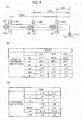
Fig. 5] Fig. 5(a) is a graph showing the relation between errors in the coordinates of thevehicle 51 and an amount (distance) by which thevehicle 51 moves from a terrestrial landmark in a travelling direction, andFig. 5(b) is a graph showing the relation between an amount (angle) by which thevehicle 51 moves from the terrestrial landmark in each rotational direction (a roll direction, a pitch direction, a yaw direction) and errors in an attitude of thevehicle 51. - [
Fig. 6] Fig. 6(a) is a diagram showingvehicles 51A to 51C travelling on a straight road LD1 alongside which terrestrial landmarks LM1 to LM3 are located,Fig. 6(b) is a table showing errors estimated by theerror estimator 16, andFig. 6(c) is a table showing self-positions detected by the self-position detector 12. - [
Fig. 7] Fig. 7(a) is a diagram showingvehicles 51A to 51C travelling on the straight road LD1 alongside which the terrestrial landmark LM1 is located, andFig. 7(b) is a table showing errors estimated by theerror estimator 16. - [
Fig. 8] Fig. 8(a) is a diagram showingvehicles Fig. 8(b) is a table showing errors estimated by theerror estimator 16, andFig. 8(c) is a table showing self-positions detected by the self-position detector 12. - [
Fig. 9] Fig. 9(a) is a diagram showingvehicles Fig. 9(b) is a table showing errors estimated by theerror estimator 16. - [
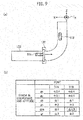
Fig. 10] Fig. 10 is a plan view showing a two-dimensional coordinate system (xl, yl) on an image (Img), including target coordinates (G1) assumed to contain no errors and target coordinates (G2) assumed to contain the maximum errors. - [
Fig. 11] Fig. 11 is a table comparing the sizes of a detection area (Z1) shown inFig. 10 . - [
Fig. 12] Fig. 12 is a flowchart showing an example of a target detection method using thetarget detection apparatus 100. - Hereinbelow, embodiments of the present invention are described with reference to the drawings. The same components are denoted by the same reference numerals and are not described to avoid repetitive description.
- With reference to
Fig. 1 , a description is given of information inputted to and outputted from atarget detection apparatus 100 of the present embodiment. Thetarget detection apparatus 100 detects a target placed near a road, from an image taken by an imager (camera) mounted in avehicle 51. The target is fixed onto the ground and includes, for example, a traffic signal and a road sign. In the embodiments herein, a traffic signal is used as an example. - The
target detection apparatus 100 receives input of map information D02, landmark information D01, and camera information D03. The map information D02 contains positional information on a target, in which a position on a map and a position in an actual environment are associated with each other beforehand. The landmark information D01 is used to calculate the self-position of thevehicle 51 in the actual environment. Landmarks include a characteristic object on the ground (terrestrial landmarks) and a Global Positioning System (GPS) satellite that transmits GPS signals receivable by thevehicle 51. In the first embodiment, a terrestrial landmark is used as an example. The landmark information D01 contains, for example, positional information on terrestrial landmarks. The camera information D03 is used to extract an image of the surroundings (e.g., the front) of thevehicle 51 from the imager. Based on these pieces of information D01 to D03, thetarget detection apparatus 100 outputs a result of recognition of a traffic signal, which is an example of the target, as traffic signal information D04. - With reference to
Fig. 2 , the configuration of thetarget detection apparatus 100 according to the present embodiment and a dataflow therein are described. Thetarget detection apparatus 100 includes animager 11, a self-position detector 12, atarget position estimator 13, adetection area setter 14, atarget detector 15, and anerror estimator 16. - The
imager 11 is mounted in thevehicle 51 and acquires an image by imaging the surroundings of thevehicle 51. Theimager 11 is a camera including a solid-state image pickup element, for example, a CCD and a CMOS, and acquires an image on which image processing can be performed. Theimager 11 sets its angle of view for the image and vertical and horizontal camera angles based on the camera information D03, and outputs an acquired image as image data D08. - The self-
position detector 12 detects the self-position of thevehicle 51 based on the amount of movement of thevehicle 51 from an initial position thereof on the map information D02, the initial position being based on the landmark information D01. The landmark information D01 indicates, for example, the relative position of a terrestrial landmark (a store, a sight, or a sightseeing spot), detected by a sensor such as an in-vehicle camera or a laser radar, with respect to thevehicle 51. In the map information D02, positional information on the terrestrial landmark is preregistered. The self-position detector 12 can detect the self-position of thevehicle 51 by checking the landmark information D01 and the relative position information on the terrestrial landmark against each other. Herein, the "position" includes coordinates and an attitude. To be more specific, the position of a terrestrial landmark includes the coordinates and attitude of the terrestrial landmark, and the position of thevehicle 51 includes the coordinates and attitude of thevehicle 51. As self-position information D05, the self-position detector 12 outputs the coordinates (x, y, z) represented in a reference coordinate system and the attitude components (pitch, yaw, and roll) in the rotational directions of the respective coordinate axes. - The
target position estimator 13 estimates the relative position of a target with respect to thevehicle 51 based on the map information D02 and the self-position information D05. In the map information D02, the positional information (coordinates information) on the target is preregistered. The relative coordinates of the target to the vehicle can be obtained from the coordinates of the target and the coordinates and attitude of thevehicle 51. Thetarget position estimator 13 outputs the estimated relative coordinates of the target as relative position information D06. - The
error estimator 16 estimates errors contained in the self-position detected by the self-position detector 12, based on the amount of movement of the vehicle from the initial position. A detailed description of theerror estimator 16 will be given later with reference toFigs. 5 to 9 . - The
detection area setter 14 sets a target detection area within an image, based on the relative position of the target. Because theimager 11 is fixed to thevehicle 51, a position on the image at which the target is likely to be imaged can be specified within the image when the angle of view of theimager 11 is determined. Based on this position on the image, thedetection area setter 14 determines the target detection area within the image. - The
detection area setter 14 adjusts the size of the target detection area according to the errors estimated by theerror estimator 16. Thedetection area setter 14 outputs the detection area thus set and adjusted, as detection area information D09. A detailed description of thedetection area setter 14 will be given later with reference toFigs. 10 and 11 . - The
target detector 15 detects the target from the detection area set and adjusted. Specifically, thetarget detector 15 performs image processing for target detection on the image data D08 within the detection area. The image processing method is not limited. In an example where the target is a traffic signal, a traffic light in the traffic signal can be detected using synchronous detection processing based on the alternating cycle of commercial power supplies or using hue and shape similarity determination processing. Other known image processing may also be used for the target detection. Performing the image processing not on the entire image data D08, but only on a part thereof (the detection area) reduces the information processing load for the target detection, allowing quick target detection. Thetarget detector 15 outputs a result of the target detection as the target information D04. - The self-
position detector 12, thetarget position estimator 13, theerror estimator 16, thedetection area setter 14, and thetarget detector 15 can be implemented using a microcontroller having a CPU, a memory, and an input and output unit. Specifically; the CPU executes preinstalled computer programs to implement the multiple information processors (12 to 16) in the microcontroller. Part of the memory in the microcontroller forms map database storing the map information D02. The microcontroller may be used also as an ECU used for other vehicle controls (e.g., autonomous driving control). - With reference to
Fig. 3 , the configuration of the self-position detector 12 shown inFig. 2 and a dataflow therein are described. The self-position detector 12 includes aninitial position detector 21 and an amount-of-movement adder 22. Theinitial position detector 21 detects the initial position of thevehicle 51 using the landmark information D01. The initial position is a position based on which the self-position of thevehicle 51 is detectable, and is the position, i.e., the coordinates and attitude, of thevehicle 51 which can be directly obtained from the landmark information D01. Alternatively, there is a case where a vehicle position detection apparatus is placed alongside the road to detect the positions of vehicles travelling within its road section, allowing positional information on thevehicle 51 to be acquired through road-to-vehicle communications or the like. In such a case, theinitial position detector 21 can acquire the position based on which the self-position of thevehicle 51 is detectable, by receiving the position of thevehicle 51 from the roadside vehicle position detection apparatus. - The amount-of-
movement adder 22 accumulatively adds an amount of movement of the vehicle to the initial position detected by theinitial position detector 21 and thereby calculates the self-position of thevehicle 51. In a case where, for example, a terrestrial landmark has been detected by a sensor, the self-position detector 12 detects information on the initial position as the self-position information D05 without the accumulative addition of the amount of movement of the vehicle. When no terrestrial landmark has been detected, the self-position detector 12 outputs, as the self-position information D05, information obtained by accumulatively adding the amount of movement of the vehicle to the initial position which has been detected most recently. The method used for the estimation of the amount of movement of the vehicle is not limited, and any known method may be used. For example, the amount-of-movement adder 22 may use an odometer, a radar, a gyroscopic sensor, a yaw-rate sensor, and a steer-angle sensor to estimate the amount of movement of the vehicle, i.e., an amount of change in the coordinates and attitude of the vehicle, per unit time. - In regard to the configuration of the self-
position detector 12 inFig. 3 , theerror estimator 16 inFig. 2 estimates errors in the self-position based on the amount of movement of thevehicle 51 which is accumulatively added by the amount-of-movement adder 22. The amount of movement of the vehicle estimated by the amount-of-movement adder 22 is lower in accuracy than the initial position detected using a landmark. When such an amount of movement of the vehicle is accumulatively added to the initial position, errors contained in the self-position are also accumulatively added. Thus, errors contained in the self-position of the vehicle are greatly affected by the amount of movement from the initial position detected using a landmark. When errors are estimated based on the amount of movement from the initial position, the errors can be estimated accurately. Details for this will be given later with reference toFigs. 5 to 9 . - With reference to
Fig. 4 , the configuration of thedetection area setter 14 inFig. 2 and a dataflow therein are described. Thedetection area setter 14 includes a targetposition error estimator 31, a coordinatetransformer 32, and anarea determiner 34. - The target
position error estimator 31 estimates errors to be caused in the relative position of the target by the errors contained in the self-position. Specifically, the targetposition error estimator 31 receives input of the relative position information D06 and error information D07. Then, the targetposition error estimator 31 estimates errors which would be caused in the relative coordinates of the target with respect to thevehicle 51 if errors estimated by theerror estimator 16 were caused in the coordinates and attitude of thevehicle 51. The targetposition error estimator 31 outputs the errors to be caused in the relative coordinates of the target, as target position error information D11. - The coordinate
transformer 32 transforms the relative coordinates of the target and their errors into coordinates on the image in which the target is imaged. Specifically, the coordinatetransformer 32 receives input of the relative position information D06 and the target position error information D11. Then, based on a lens optical system in theimager 11, the coordinatetransformer 32 transforms the coordinates of the target in the three-dimensional coordinate system (x, y, z) into ones on the image in the two-dimensional coordinate system (xl, yl). The method for the coordinate transformation is not limited, and any known method may be used. The coordinatetransformer 32 outputs the two-dimensional coordinates of the target assumed to contain no errors and the two dimensional coordinates of the target assumed to contain the maximum errors as lens coordinate information D12. - The
area determiner 34 determines the size of a detection area based on the difference between the coordinates assumed to contain no errors and the coordinates assumed to contain the maximum errors, and determines the coordinates of the center of the detection area based on the coordinates assumed to contain no errors. Details for this will be given later with reference toFig. 10 . The size and center coordinates of the detection area are outputted as the detection area information D09. - With reference to
Figs. 5 to 9 , a description is given of errors in the self-position estimated based on the amount of movement of thevehicle 51 which is accumulatively added by the amount-of-movement adder 22. The horizontal axis inFig. 5(a) represents the amount of movement of thevehicle 51 from the initial position in a travelling direction (z direction), and the vertical axis inFig. 5(a) represents errors (gx, gy, gz) contained in the coordinates of thevehicle 51. Specifically, gz denotes an error in the travelling direction of thevehicle 51, gx denotes an error in a width direction of thevehicle 51 and gy denotes an error in a height direction of thevehicle 51. - The errors (gx, gy, gz) contained in the coordinates of the
vehicle 51 increase in proportion to the amount of movement from the initial position. When the amount of movement from the initial position is zero, the errors (gx, gy, gz) are also zero. Note thatFig. 5(a) does not consider errors contained in the initial position detected by theinitial position detector 21. The coordinates of thevehicle 51 are calculated by accumulative addition of amounts of change in coordinates per unit time to the initial position. For this reason, when the amount of movement from the initial position is larger, larger amounts of change in coordinates are accumulatively added, increasing the errors to be contained in the coordinates of thevehicle 51. In relation to the amount of movement in the z direction (the travelling direction), the error in the width direction of the vehicle 51 (gx) is the largest, and the error in the height direction of the vehicle (gy) is the smallest. - The horizontal axis in
Fig. 5(b) represents an amount of movement of the vehicle 51 (an amount of angular change) in each rotational direction (the roll direction, the pitch direction, and the yaw direction) from the initial position, and the vertical axis inFig. 5(b) represents errors (gr, gp, gya) contained in the attitude of thevehicle 51. Specifically, gr denotes an error in the roll direction of thevehicle 51, gp denotes an error in the pitch direction of thevehicle 51, and gya denotes an error in the yaw direction of thevehicle 51. - The errors (gr, gp, gya) contained in the attitude of the
vehicle 51 increase in proportion to the amount of change in attitude from the attitude of thevehicle 51 at the initial position (i.e., an initial attitude). When the amounts of change from the initial attitude are zero, predetermined errors (gr, gp, gya) are caused. In other words,Fig. 5(b) considers errors contained in the initial attitude detected by theinitial position detector 21. The attitude of thevehicle 51 is calculated by accumulative addition of the amounts of change in attitude per unit time to the initial attitude. For this reason, when the amounts of change from the initial attitude are large, larger amounts of change in attitude are accumulatively added, increasing the errors (gr, gp, gya) to be contained in the attitude of thevehicle 51. In relation to the amounts of change in the rotational directions, the errors in the roll direction (gr) and the pitch direction (gp) are the largest, and the error in the yaw direction (gya) is the smallest. When thevehicle 51 rotates in the yaw direction, only the error in the yaw direction (gya) is caused. The same is true of the roll direction and the pitch direction. - Next, the error estimation by the
error estimator 16 and the self-position detection by the self-position detector 12 are described using specific examples of the road shapes and terrestrial landmarks shown inFigs. 6 to 9 . -
Fig. 6(a) showsvehicles 51A to 51C travelling on a straight road LD1 alongside which terrestrial landmarks LM1 to LM3 are placed.Fig. 6(b) is a table showing errors estimated by theerror estimator 16, andFig. 6(c) is a table showing self-positions detected by the self-position detector 12. Thevehicle 51A shows the position of the vehicle making its closest approach to the terrestrial landmark LM1. Similarly, thevehicle 51B and thevehicle 51C show the positions of the vehicle making its closest approach to the terrestrial landmarks LM2 and LM3, respectively. A traffic signal, which is an example of a target Tgt, is away from thevehicles - At each of the points of the
vehicles 51 A to 51C, the self-position detector 12 can calculate the self-position by using the initial position of thevehicle 51 as it is without accumulative addition of the amount of movement of the vehicle. Thus, as shown inFig. 6(b) , errors estimated by theerror estimator 16 at the points of thevehicles 51A to 51C are equal to errors contained in the initial attitude detected by theinitial position detector 21. Since thevehicle 51 is travelling on the straight road LD1, the self-position detected by the self-position detector 12 changes only in the coordinate (z) in the travelling direction (z direction), as shown inFig. 6(c) . The target Tgt is the origin of the coordinates shown inFig. 6(c) . The units are as follows: gx [m], gy [m], gz [m], gp [°], gya [°], gr [°], x [m], y [m], z [m], pitch [°], yaw [°], and roll [°]. -
Fig. 7(a) shows another example where only the terrestrial landmark LM1 is placed alongside the straight road LD1. At the point of thevehicle 51A, the self-position detector 12 can calculate the self-position by using the initial position of thevehicle 51 as it is without accumulative addition of the amount of movement of the vehicle. Thus, as shown inFig. 7(b) , the same errors as those inFig. 6(b) are caused in the coordinates and attitude at the point of thevehicle 51 A. Because the terrestrial landmarks LM2 and LM3 are not placed, the self-positions at thevehicles vehicle 51A. Thus, errors in the coordinates at thevehicle 51B and thevehicle 51C are different from those inFig. 6(b) . Theerror estimator 16 refers to the data shown inFig. 5(a) and calculates errors in the coordinates based on amounts of movement from thevehicle 51 A (80 m, 160 m). The longer the amount of movement from thevehicle 51 A, the larger the errors in the coordinates (gx, gy, gz). Because thevehicle 51 does not move in the rotational directions in this example, errors in attitude at thevehicles Fig. 6(b) . -
Fig. 8(a) shows thevehicles Fig. 8(b) is a table showing errors estimated by theerror estimator 16, andFig. 8(c) is a table showing self-positions detected by the self-position detector 12. Thevehicles - At each point of the
vehicles position detector 12 can calculate the self-position by using the initial position of thevehicle 51 as it is without accumulative addition of the amount of movement of the vehicle. Thus, as shown inFig. 8(b) , errors estimated by theerror estimator 16 at the points of thevehicles initial position detector 21. The target Tgt is the origin of the coordinates shown inFig. 8(c) . -
Fig. 9(a) shows another example where only the terrestrial landmark LM1 is placed alongside the curved road LD2. At the point of thevehicle 51 A, the self-position detector 12 can calculate the self-position by using the initial position of thevehicle 51 as it is without accumulative addition of the amount of movement of the vehicle. Thus, as shown inFig. 9(b) , the same errors as those inFig. 8(b) are caused in the coordinates and attitude at the point of thevehicle 51A. Because the terrestrial landmark LM2 is not placed, the self-position at thevehicle 51B is calculated through accumulative addition of the amount of movement from thevehicle 51A. Between thevehicle 51A andvehicle 51B, the vehicle is rotated in the yaw direction by 90°. Theerror estimator 16 refers to the data shown inFig. 5(b) and calculates an error in the yaw direction based on the amount of movement from thevehicle 51A. As shown inFig. 9(b) , the error in the yaw direction (gya) is increased at the vehicle 5IB. Between thevehicle 51A and thevehicle 51B, the coordinates of the vehicle also change in addition to the attitude of the vehicle. However, in this example, only the change in attitude is taken into consideration, and the change in coordinates is not taken into consideration. - With reference to
Fig. 10 , an example method of determining the size and center coordinates of a detection area is described.Fig. 10 is a plan view showing a two-dimensional coordinate system (x1, yl) on an image (Img). Coordinates (G1) are two-dimensional coordinates of a target assumed to contain no errors, after the coordinate transformation by the coordinatetransformer 32. Coordinates (G2) are two-dimensional coordinates of a target assumed to contain the maximum errors, after the coordinate transformation by the coordinatetransformer 32. The differences (Xm, Ym) between the coordinates (G1) and the coordinates (G2) correspond to errors contained in the relative coordinates of the target which have been subjected to the coordinate transformation by the coordinatetransformer 32. - The
detection area setter 14 determines a detection area (Z1) having the coordinates (G1) as its center coordinates and four sides obtained by adding, to the size of the target, a length of 2×Xm in the x direction and a length of 2×Ym in the y direction. With such a detection area (Z1), even the maximum errors cause the coordinates (G2) of the target to fall within the detection area (Z1), making it unlikely for the target to be outside the detection area. Moreover, because the detection area (Z1) is not increased excessively, erroneous detection of an object other than the target is unlikely, and also, detection of the target can be achieved with less computing load. - Alternatively, the
detection area setter 14 may select a detection area (Z1) having the closest size out of a plurality of predetermined detection areas (Z1) of different sizes. - With reference to
Fig. 11 , the detection areas (Z1) in the examples shown inFigs. 6 to 9 are compared in size. Here, the size of the detection area (Z1) at thevehicle 51C inFig. 6 and at thevehicle 51B inFig. 8 is set as the reference (x). Thevehicle 51B inFig. 6 is the same as thevehicle 51C inFig. 6 in the errors contained in the self-position (coordinates and attitude), but is different from thevehicle 51C inFig. 6 in the distance to the target. Thus, the size of the detection area (Z1) at thevehicle 51B inFig. 6 is three times the reference value (x). Due to the absence of a terrestrial landmark, thevehicle 51B inFig. 7 has errors caused by the accumulative addition of the amount of movement. For this reason, the size of the detection area (Z1) is further increased to five times the reference value (x). At thevehicle 51C inFig. 7 , the errors caused by the accumulative addition of the amount of movement increases even more, but the distance to the target decreases. Thus, the size of the detection area (Z1) decreases to twice the reference value (x). Similarly, thevehicle 51B inFig. 9 has errors caused by the accumulative addition of the amount of movement; therefore, the size of the detection area (Z1) is twice the reference value (x). - As described above, when the distance to the target is long, the errors in the yaw direction and the pitch direction (gya, gp) are significant, and therefore, the detection area needs to be large. On the other hand, when the distance to the target is short, the errors in the coordinates (gx, gy, gz) are significant, and therefore, the size of the detection area (Z1) differs depending on whether the landmark information is present or absent.
- With reference to
Fig. 12 , an example of a target detection method using thetarget detection apparatus 100 is described. - In Step S01, the
imager 11 acquires an image by imaging the surroundings of thevehicle 51 based on the camera information D03. In Step S03, the self-position detector 12 obtains an initial position of thevehicle 51 from the landmark information D01, detects the self-position of the vehicle based on an amount of movement of thevehicle 51 from the initial position, and outputs the detected self-position as the self-position information D05. - In Step S05, based on the map information D02 and the self-position information D05, the
target position estimator 13 estimates the relative position of the target with respect to thevehicle 51. In Step S07, based on the self-position detected in Step S03, theerror estimator 16 estimates error (Ds) contained in the self-position. To be more specific, by reference toFigs. 5(a) and 5(b) , theerror estimator 16 estimates errors (gx, gy, gz, gr, gp, gya) contained in the self-position of thevehicle 51 according to amounts of movement (distance and angle) from the initial position. - In Step S09, it is determined whether the estimated error (Ds) is larger than threshold (Dth) predetermined. When the error (Ds) is larger than the threshold (Dth) (YES in S09), large errors are caused in the relative position of the target. Then, there is a high necessity for the detection area (Z1) to be adjusted in size according to the errors. Thus, in
Step S 13, the targetposition error estimator 31 estimates errors caused in the relative position of the target by the errors contained in the self-position. - The threshold (Dth) can be set for each of the errors contained in the coordinates of the vehicle (gx, gy, gz) and each of the errors contained in the attitude of the vehicle (gr, gp, gya). Then, when any one of these errors is larger than its threshold, an affirmative determination (YES) is made in Step S09. Alternatively, an affirmative determination (YES) may be made in Step S09 only when all of the errors are larger than their thresholds.
- In Step S15, as shown in
Fig. 10 , the coordinatetransformer 32 transforms the relative coordinates of the target and their errors into coordinates (xl, yl) on the image (Img) of the target. In Step S17, as shown inFig. 11 , thearea determiner 34 sets the size of the detection area (Z1) based on the differences (Xm, Ym) between the coordinates (G1) assumed to contain no errors and the coordinates (G2) assumed to contain the maximum errors. InStep S 19, thearea determiner 34 determines the center coordinates of the detection area (Z1) based on the coordinates (G1) assumed to contain no errors. The detection area (Z1) is thus determined. - Meanwhile, when the error (Ds) is equal to or smaller than the threshold (Dth) (NO in S09), small errors are caused in the relative position of the target. Then, there is a low necessity for the detection area (Z1) to be adjusted in size according to the errors. Thus, in Step S11, the coordinate
transformer 32 performs coordinate transformation on the relative coordinates of the target estimated in Step S05 and obtains the coordinates (G1) assumed to contain no errors. In Step S19, thearea determiner 34 determines the center coordinates of the detection area (Z1) based on the coordinates (G1) assumed to contain no errors. The size of the detection area (Z1) in this case is a predetermined value, which is for example the reference value (x) inFig. 11 . In other words, when the error (Ds) is equal to or smaller than the threshold (Dth), the detection area (Z1) is determined with its size not adjusted according to the error (Ds). - In Step S21, the
area determiner 34 determines whether the amount of change in the error (Ds) between the previous error and the current error is equal to or larger than a predetermined reference value. When the amount of change in the error (Ds) is equal to or larger than the predetermined value (YES in S21), the flow proceeds to Step S23 in which thearea determiner 34 stores the amount of size adjustment to the detection area in the memory, as an example of the detection area information D09. When the amount of change in the error (Ds) is smaller than the predetermined reference value (NO in S21), thearea determiner 34 does not update the amount of size adjustment to the detection area. Then, in Step S25, thetarget detector 15 performs image processing for target detection on the image data D08 within the detection area set and adjusted. - The target detection apparatus according to the first embodiment described above offers the following advantageous effects.
- The target detection apparatus estimates the error (Ds) contained in the self-position of the
vehicle 51 based on the amount of movement of the vehicle from its initial position, and then adjusts the size of the target detection area (Z1) according to the error (Ds). The target detection area (Z1) can thus be adjusted in size with the error (Ds) taken into consideration. Thus, even when the error (Ds) is greatly affected by the environment of the vehicle, the size of the detection area (Z1) can be set appropriately according to the error (Ds). For example, the detection area is increased in size when the error is large, so that the target will unlikely be outside the detection area. Conversely, the detection area is decreased in size when the error is small, so that an object other than the target will unlikely be erroneously detected. Image processing load is also reduced. When the size of the target detection area is thus appropriately adjusted with the error contained in the self-position of the vehicle taken into consideration, the target can be detected accurately. Even when there is an error, the target can be detected with less computation load within a detection area which is defined as small as possible but large enough to recognize the target. - The error (Ds) contained in the self-position of the
vehicle 51 is greatly affected by the amount of movement which is accumulatively added to an initial position detected using a landmark (e.g., the terrestrial landmarks LM1 to LM3). Thus, the error can be estimated accurately by error estimation that is based on the amount of movement from the initial position. - The self-
position detector 12 can detect the self-position accurately by checking the positional information on a characteristic object on the ground (the terrestrial landmarks LM1 to LM3) and the map information D02 against each other. Thus, the error (Ds) can be accurately estimated based on the amount of movement from the landmark to the self-position. - As the self-position, the self-
position detector 12 detects the coordinates of the vehicle and the attitude of the vehicle. Theerror estimator 16 estimates errors contained in the coordinates of the vehicle based on the amount of movement in the travelling direction of the vehicle, and estimates the errors contained in the attitude of the vehicle based on the amount of movement in the rotational directions of the vehicle. This enables accurate estimation of the error (Ds) contained in the self-position of the vehicle, and in turn, enables accurate estimation of error in the relative position of the target which is caused by the error (Ds). - The
area determiner 34 retains the amount of size adjustment to the detection area when the amount of change in the error (Ds) is equal to or larger than the predetermined reference value. This allows retention of the latest detection area information D09. - A second embodiment is described taking an example where the self-position is detected using, instead of a landmark, a GPS satellite that transmits GPS signals receivable by the
vehicle 51. The self-position detector 12 receives a GPS signal as the landmark information D01 and detects an initial position (initial coordinates and initial attitude) of thevehicle 51 from the GPS signal. - The
vehicle 51 might not be able to receive GPS signals due to the environment of the vehicle, for example, when there are many buildings surrounding the vehicle to block the GPS signals. In such a case, the self-position detector 12 calculates the self-position of the vehicle by accumulatively adding the amount of movement of the vehicle to the initial position detected by theinitial position detector 21. - The
initial position detector 21 inFig. 3 detects the initial position of thevehicle 51 using a GPS signal. The initial position is the position, i.e., the coordinates and attitude, of thevehicle 51 directly obtainable from the GPS signal. When no GPS signal is received, the amount-of-movement adder 22 calculates the self-position of thevehicle 51 by accumulatively adding the amount of movement of the vehicle to the initial position obtained by the GPS signal received most recently. - For example, when GPS signals are being received, the self-
position detector 12 detects information on the initial position as the self-position information D05, without the accumulative addition of the amount of movement of the vehicle. When GPS signals are not being received, the self-position detector 12 outputs, as the self-position information D05, information on a position obtained by accumulatively adding the amount of movement of the vehicle to the initial position detected most recently. - In the examples shown in
Fig. 6(a) to 9(a) , the positions of thevehicles 51A to 51C making their closest approach to the terrestrial landmarks LM1 to LM3, respectively, correspond to points at which the initial positions of thevehicle 51 are detected by reception of GPS signals. - Other configurations for the
target detection apparatus 100 and the target detection method are the same as those in the first embodiment, and therefore not described to avoid repetitive description. - As described above, the self-
position detector 12 detects the self-position by using the GPS satellite as a landmark, and theerror estimator 16 estimates error based on the amount of movement from a vehicle position of most-recent reception of a signal transmitted from the GPS satellite, to the self-position. The initial position can be accurately detected by use of a GPS signal transmitted from the GPS satellite. The error (Ds) can be estimated accurately based on the amount of movement from reception of a GPS signal to the self-position. - The present invention has been described above using the embodiments. However, the present invention is not limited to what has been described above and can be variously modified and improved, as is apparent to those skilled in the art.
- For example, the self-
position detector 12 may detect the self-position using both of a terrestrial landmark and a GPS satellite as a landmark. In this case, theerror estimator 16 may estimate the error (Ds) based on the amount of movement from either most-recent detection of a terrestrial landmark or most-recent reception of a GPS signal to the self-position. - When the
vehicle 51 can communicate with a terrestrial landmark, the relative position of the terrestrial landmark and thevehicle 51 with respect to each other can be acquired by communication, as with the case of using a GPS satellite. In this case, theerror estimator 16 may estimate the error (Ds) based on the amount of movement from most-recent reception of a position communicated from the terrestrial landmark, to the self-position. - There is a case where a vehicle position detection apparatus is installed alongside the road to detect the positions of vehicles travelling within its road section, enabling positional information on a vehicle to be acquired through road-to-vehicle communications or the like. In such a case, the self-
position detector 12 may detect the self-position of thevehicle 51 by road-to-vehicle communications or the like with the roadside vehicle position detection apparatus. Then, theerror estimator 16 may estimate the error (Ds) based on the amount of movement from most-recent reception of the vehicle position (initial position) communicated from the roadside vehicle position detection apparatus, to the self-position. -
- 11
- imager
- 12
- self-position detector
- 13
- target position estimator
- 14
- detection area setter
- 15
- target detector
- 16
- error estimator
- 21
- initial position detector
- 22
- amount-of-movement adder
- Z1
- detection area
Claims (6)
- A target detection apparatus comprising:an imager mounted in a vehicle and configured to acquire an image by imaging surroundings of the vehicle;a self-position detector configured to detect a self-position of the vehicle based on an amount of movement of the vehicle from an initial position of the vehicle;a target position estimator configured to estimate a relative position of a target, which is located around the vehicle, with respect to the vehicle based on the self-position and information on a position of the target on a map;a detection area setter configured to set a detection area for the target within the image based on the relative position of the target with respect to the vehicle;a target detector configured to detect the target from the detection area; andan error estimator configured to estimate error contained in the self-position detected by the self-position detector, based on the amount of movement of the vehicle from the initial position, whereinthe detection area setter adjusts a size of the detection area for the target according to the error estimated by the error estimator.
- The target detection apparatus according to claim 1, wherein
the self-position detector includesan initial position detector configured to detect the initial position of the vehicle by using a landmark, andan amount-of-movement adder configured to calculate the self-position by accumulatively adding the amount of movement of the vehicle to the initial position, andthe error estimator estimates the error based on the amount of movement of the vehicle from the initial position of the vehicle. - The target detection apparatus according to claim 2, wherein
the initial position detector detects the initial position by using a GPS satellite as the landmark, and
the error estimator estimates the error based on the amount of movement of the vehicle from the initial position corresponding to most-recent reception of a signal transmitted from the GPS satellite. - The target detection apparatus according to any one of claims 1 to 3, wherein as the self-position, the self-position detector detects coordinates of the vehicle and an attitude of the vehicle, and
the error estimator estimates error contained in the coordinates of the vehicle based on an amount of movement of the vehicle in a travelling direction, and estimates error contained in the attitude of the vehicle based on an amount of movement of the vehicle in a rotational direction. - The target detection apparatus according to any one of claims 1 to 4, wherein the detection area setter retains an amount of the adjustment to the size of the detection area when an amount of change in the error is equal to or larger than a predetermined reference value.
- A target detection method comprising:acquiring an image by imaging surroundings of a vehicle using an imager mounted in the vehicle;detecting a self-position of the vehicle based on an amount of movement of the vehicle from an initial position of the vehicle;estimating a relative position of a target, which is located around the vehicle, with respect to the vehicle based on the self-position and information on a position of the target on a map;setting a detection area for the target within the image based on the relative position of the target with respect to the vehicle;estimating error contained in the self-position based on the amount of movement of the vehicle from the initial position;adjusting a size of the detection area for the target according to the error; anddetecting the target from the detection area.
Applications Claiming Priority (1)
| Application Number | Priority Date | Filing Date | Title |
|---|---|---|---|
| PCT/JP2014/063351 WO2015177865A1 (en) | 2014-05-20 | 2014-05-20 | Object detection device and object detection method |
Publications (3)
| Publication Number | Publication Date |
|---|---|
| EP3147629A1 true EP3147629A1 (en) | 2017-03-29 |
| EP3147629A4 EP3147629A4 (en) | 2017-04-05 |
| EP3147629B1 EP3147629B1 (en) | 2019-07-10 |
Family
ID=54553563
Family Applications (1)
| Application Number | Title | Priority Date | Filing Date |
|---|---|---|---|
| EP14892586.0A Active EP3147629B1 (en) | 2014-05-20 | 2014-05-20 | Object detection device and object detection method |
Country Status (8)
| Country | Link |
|---|---|
| US (1) | US9767372B2 (en) |
| EP (1) | EP3147629B1 (en) |
| JP (1) | JP6222353B2 (en) |
| CN (1) | CN106461403B (en) |
| BR (1) | BR112016026372B1 (en) |
| MX (1) | MX355397B (en) |
| RU (1) | RU2633641C1 (en) |
| WO (1) | WO2015177865A1 (en) |
Families Citing this family (16)
| Publication number | Priority date | Publication date | Assignee | Title |
|---|---|---|---|---|
| JP6361366B2 (en) * | 2014-08-18 | 2018-07-25 | 株式会社デンソー | Object recognition device |
| EP3104189B1 (en) * | 2015-06-11 | 2020-09-30 | Veoneer Sweden AB | Misalignment estimation for a vehicle radar system |
| JP6756101B2 (en) * | 2015-12-04 | 2020-09-16 | トヨタ自動車株式会社 | Object recognition device |
| JP6380422B2 (en) * | 2016-02-05 | 2018-08-29 | トヨタ自動車株式会社 | Automated driving system |
| JP6575685B2 (en) * | 2016-07-26 | 2019-09-18 | 日産自動車株式会社 | Self-position estimation method and self-position estimation apparatus |
| DE102017220139A1 (en) * | 2017-11-13 | 2019-05-16 | Robert Bosch Gmbh | Method and device for providing a position of at least one object |
| US20210016794A1 (en) * | 2018-03-30 | 2021-01-21 | Toyota Motor Europe | System and method for adjusting external position information of a vehicle |
| US10839522B2 (en) * | 2018-05-11 | 2020-11-17 | Toyota Research Institute, Inc. | Adaptive data collecting and processing system and methods |
| WO2020137313A1 (en) * | 2018-12-28 | 2020-07-02 | パナソニックIpマネジメント株式会社 | Localization device |
| CN112149659B (en) * | 2019-06-27 | 2021-11-09 | 浙江商汤科技开发有限公司 | Positioning method and device, electronic equipment and storage medium |
| JP7227112B2 (en) * | 2019-09-27 | 2023-02-21 | 日立Astemo株式会社 | OBJECT DETECTION DEVICE, TRIP CONTROL SYSTEM, AND TRIP CONTROL METHOD |
| JP7226583B2 (en) * | 2019-11-12 | 2023-02-21 | 日産自動車株式会社 | Traffic light recognition method and traffic light recognition device |
| EP3825731B1 (en) * | 2019-11-21 | 2022-01-05 | Sick Ag | Optoelectronic safety sensor and method for guaranteed determination of own position |
| EP3929613A1 (en) * | 2020-06-22 | 2021-12-29 | Carnegie Robotics, LLC | A method for navigating a movable device along an inclined surface |
| US11935292B2 (en) | 2020-06-22 | 2024-03-19 | Carnegie Robotics, Llc | Method and a system for analyzing a scene, room or venue |
| CN115993089B (en) * | 2022-11-10 | 2023-08-15 | 山东大学 | PL-ICP-based online four-steering-wheel AGV internal and external parameter calibration method |
Citations (3)
| Publication number | Priority date | Publication date | Assignee | Title |
|---|---|---|---|---|
| EP2019382A1 (en) * | 2006-05-15 | 2009-01-28 | Toyota Jidosha Kabushiki Kaisha | Support control device |
| US20100061591A1 (en) * | 2006-05-17 | 2010-03-11 | Toyota Jidosha Kabushiki Kaisha | Object recognition device |
| WO2013133129A1 (en) * | 2012-03-06 | 2013-09-12 | 日産自動車株式会社 | Moving-object position/attitude estimation apparatus and method for estimating position/attitude of moving object |
Family Cites Families (16)
| Publication number | Priority date | Publication date | Assignee | Title |
|---|---|---|---|---|
| JP2526876B2 (en) * | 1986-11-17 | 1996-08-21 | 日本電装株式会社 | Vehicle traveling position display device |
| RU2109344C1 (en) * | 1993-08-06 | 1998-04-20 | Николай Николаевич Токарев | Method of detection of moving targets and device for its realization |
| JP3449240B2 (en) * | 1998-09-24 | 2003-09-22 | 株式会社デンソー | Vehicle current position detection device, vehicle current position display device, navigation device, and recording medium |
| WO2005038402A1 (en) * | 2003-10-21 | 2005-04-28 | Waro Iwane | Navigation device |
| JP4763250B2 (en) * | 2004-04-09 | 2011-08-31 | 株式会社デンソー | Object detection device |
| WO2005122113A1 (en) * | 2004-06-07 | 2005-12-22 | Sharp Kabushiki Kaisha | Information display control device, navigation device, controlling method of information display control device, control program of information display control device, and computer-readable storage medium |
| EP1901225A1 (en) * | 2005-05-10 | 2008-03-19 | Olympus Corporation | Image processing device, image processing method, and image processing program |
| JP4631750B2 (en) * | 2006-03-06 | 2011-02-16 | トヨタ自動車株式会社 | Image processing system |
| EP1906339B1 (en) * | 2006-09-01 | 2016-01-13 | Harman Becker Automotive Systems GmbH | Method for recognizing an object in an image and image recognition device |
| JP4573899B2 (en) * | 2006-12-21 | 2010-11-04 | パイオニア株式会社 | Navigation device, map matching method, and map matching program |
| JP2008287572A (en) * | 2007-05-18 | 2008-11-27 | Sumitomo Electric Ind Ltd | Vehicle driving support system, driving support device, vehicle, and vehicle driving support method |
| JP2009259215A (en) * | 2008-03-18 | 2009-11-05 | Zenrin Co Ltd | Road surface marking map generation method |
| JP4453775B2 (en) * | 2008-06-27 | 2010-04-21 | トヨタ自動車株式会社 | Object detection device |
| JP5372680B2 (en) * | 2009-09-24 | 2013-12-18 | 日立オートモティブシステムズ株式会社 | Obstacle detection device |
| JP5873867B2 (en) * | 2011-06-13 | 2016-03-01 | パナソニック インテレクチュアル プロパティ コーポレーション オブアメリカPanasonic Intellectual Property Corporation of America | Noise pattern acquisition device and position detection device including the same |
| US20150025838A1 (en) * | 2011-11-15 | 2015-01-22 | Panasonic Corporation | Position estimation device, position estimation method, and integrated circuit |
-
2014
- 2014-05-20 BR BR112016026372-3A patent/BR112016026372B1/en active IP Right Grant
- 2014-05-20 MX MX2016014733A patent/MX355397B/en active IP Right Grant
- 2014-05-20 WO PCT/JP2014/063351 patent/WO2015177865A1/en active Application Filing
- 2014-05-20 CN CN201480079086.XA patent/CN106461403B/en active Active
- 2014-05-20 EP EP14892586.0A patent/EP3147629B1/en active Active
- 2014-05-20 US US15/311,250 patent/US9767372B2/en active Active
- 2014-05-20 RU RU2016146709A patent/RU2633641C1/en active
- 2014-05-20 JP JP2016520844A patent/JP6222353B2/en active Active
Patent Citations (3)
| Publication number | Priority date | Publication date | Assignee | Title |
|---|---|---|---|---|
| EP2019382A1 (en) * | 2006-05-15 | 2009-01-28 | Toyota Jidosha Kabushiki Kaisha | Support control device |
| US20100061591A1 (en) * | 2006-05-17 | 2010-03-11 | Toyota Jidosha Kabushiki Kaisha | Object recognition device |
| WO2013133129A1 (en) * | 2012-03-06 | 2013-09-12 | 日産自動車株式会社 | Moving-object position/attitude estimation apparatus and method for estimating position/attitude of moving object |
Non-Patent Citations (1)
| Title |
|---|
| See also references of WO2015177865A1 * |
Also Published As
| Publication number | Publication date |
|---|---|
| EP3147629B1 (en) | 2019-07-10 |
| MX2016014733A (en) | 2017-03-06 |
| JP6222353B2 (en) | 2017-11-08 |
| BR112016026372A2 (en) | 2017-08-15 |
| RU2633641C1 (en) | 2017-10-16 |
| US20170177958A1 (en) | 2017-06-22 |
| WO2015177865A1 (en) | 2015-11-26 |
| MX355397B (en) | 2018-04-18 |
| US9767372B2 (en) | 2017-09-19 |
| BR112016026372B1 (en) | 2022-03-03 |
| CN106461403B (en) | 2019-02-15 |
| EP3147629A4 (en) | 2017-04-05 |
| JPWO2015177865A1 (en) | 2017-04-20 |
| CN106461403A (en) | 2017-02-22 |
Similar Documents
| Publication | Publication Date | Title |
|---|---|---|
| EP3147629A1 (en) | Object detection device and object detection method | |
| US10520949B2 (en) | Method and device for localizing a vehicle in its surroundings | |
| US10788830B2 (en) | Systems and methods for determining a vehicle position | |
| EP2950292B1 (en) | Driving support device, driving support method, and recording medium storing driving support program | |
| KR101628427B1 (en) | Deadreckoning-based navigation system using camera and control method thereof | |
| US10024668B2 (en) | Position estimation system, position estimation method and mobile unit | |
| US20180267172A1 (en) | System and method for recognizing position of vehicle | |
| WO2019022948A1 (en) | Determining yaw error from map data, lasers, and cameras | |
| EP2983153A1 (en) | Signal recognition device | |
| US10262533B2 (en) | Moving object and driving support system for moving object | |
| US20180154901A1 (en) | Method and system for localizing a vehicle | |
| US20190001978A1 (en) | Vehicle control method and apparatus | |
| KR102086270B1 (en) | Control method and traveling control device of the traveling control device | |
| KR102331312B1 (en) | 3D vehicular navigation system using vehicular internal sensor, camera, and GNSS terminal | |
| KR20150078881A (en) | Method for measureling position of vehicle using cloud computing | |
| US20220113139A1 (en) | Object recognition device, object recognition method and program | |
| JP2022068242A (en) | Road surface information acquisition method | |
| JP2018189463A (en) | Vehicle position estimating device and program | |
| CN113795726B (en) | Self-position correction method and self-position correction device | |
| JP2023126399A (en) | Measuring device, measuring method and program | |
| JP2023076673A (en) | Information processing device, control method, program and storage medium | |
| CN110023781B (en) | Method and device for determining the exact position of a vehicle from a radar signature of the surroundings of the vehicle | |
| KR102622587B1 (en) | Apparatus and method for correcting longitudinal position error of fine positioning system | |
| TW202229818A (en) | Lane mapping and localization using periodically-updated anchor frames | |
| JP2018169207A (en) | Vehicle position detector |
Legal Events
| Date | Code | Title | Description |
|---|---|---|---|
| STAA | Information on the status of an ep patent application or granted ep patent |
Free format text: STATUS: THE INTERNATIONAL PUBLICATION HAS BEEN MADE |
|
| PUAI | Public reference made under article 153(3) epc to a published international application that has entered the european phase |
Free format text: ORIGINAL CODE: 0009012 |
|
| STAA | Information on the status of an ep patent application or granted ep patent |
Free format text: STATUS: REQUEST FOR EXAMINATION WAS MADE |
|
| 17P | Request for examination filed |
Effective date: 20161202 |
|
| AK | Designated contracting states |
Kind code of ref document: A1 Designated state(s): AL AT BE BG CH CY CZ DE DK EE ES FI FR GB GR HR HU IE IS IT LI LT LU LV MC MK MT NL NO PL PT RO RS SE SI SK SM TR |
|
| AX | Request for extension of the european patent |
Extension state: BA ME |
|
| A4 | Supplementary search report drawn up and despatched |
Effective date: 20170303 |
|
| RIC1 | Information provided on ipc code assigned before grant |
Ipc: G01C 21/30 20060101AFI20170227BHEP Ipc: G06K 9/00 20060101ALI20170227BHEP |
|
| DAX | Request for extension of the european patent (deleted) | ||
| STAA | Information on the status of an ep patent application or granted ep patent |
Free format text: STATUS: EXAMINATION IS IN PROGRESS |
|
| 17Q | First examination report despatched |
Effective date: 20180125 |
|
| GRAP | Despatch of communication of intention to grant a patent |
Free format text: ORIGINAL CODE: EPIDOSNIGR1 |
|
| STAA | Information on the status of an ep patent application or granted ep patent |
Free format text: STATUS: GRANT OF PATENT IS INTENDED |
|
| INTG | Intention to grant announced |
Effective date: 20190322 |
|
| GRAS | Grant fee paid |
Free format text: ORIGINAL CODE: EPIDOSNIGR3 |
|
| GRAA | (expected) grant |
Free format text: ORIGINAL CODE: 0009210 |
|
| STAA | Information on the status of an ep patent application or granted ep patent |
Free format text: STATUS: THE PATENT HAS BEEN GRANTED |
|
| AK | Designated contracting states |
Kind code of ref document: B1 Designated state(s): AL AT BE BG CH CY CZ DE DK EE ES FI FR GB GR HR HU IE IS IT LI LT LU LV MC MK MT NL NO PL PT RO RS SE SI SK SM TR |
|
| REG | Reference to a national code |
Ref country code: GB Ref legal event code: FG4D |
|
| REG | Reference to a national code |
Ref country code: CH Ref legal event code: EP Ref country code: AT Ref legal event code: REF Ref document number: 1154067 Country of ref document: AT Kind code of ref document: T Effective date: 20190715 |
|
| REG | Reference to a national code |
Ref country code: DE Ref legal event code: R096 Ref document number: 602014050000 Country of ref document: DE |
|
| REG | Reference to a national code |
Ref country code: IE Ref legal event code: FG4D |
|
| REG | Reference to a national code |
Ref country code: NL Ref legal event code: MP Effective date: 20190710 |
|
| REG | Reference to a national code |
Ref country code: LT Ref legal event code: MG4D |
|
| REG | Reference to a national code |
Ref country code: AT Ref legal event code: MK05 Ref document number: 1154067 Country of ref document: AT Kind code of ref document: T Effective date: 20190710 |
|
| PG25 | Lapsed in a contracting state [announced via postgrant information from national office to epo] |
Ref country code: BG Free format text: LAPSE BECAUSE OF FAILURE TO SUBMIT A TRANSLATION OF THE DESCRIPTION OR TO PAY THE FEE WITHIN THE PRESCRIBED TIME-LIMIT Effective date: 20191010 Ref country code: NO Free format text: LAPSE BECAUSE OF FAILURE TO SUBMIT A TRANSLATION OF THE DESCRIPTION OR TO PAY THE FEE WITHIN THE PRESCRIBED TIME-LIMIT Effective date: 20191010 Ref country code: AT Free format text: LAPSE BECAUSE OF FAILURE TO SUBMIT A TRANSLATION OF THE DESCRIPTION OR TO PAY THE FEE WITHIN THE PRESCRIBED TIME-LIMIT Effective date: 20190710 Ref country code: SE Free format text: LAPSE BECAUSE OF FAILURE TO SUBMIT A TRANSLATION OF THE DESCRIPTION OR TO PAY THE FEE WITHIN THE PRESCRIBED TIME-LIMIT Effective date: 20190710 Ref country code: FI Free format text: LAPSE BECAUSE OF FAILURE TO SUBMIT A TRANSLATION OF THE DESCRIPTION OR TO PAY THE FEE WITHIN THE PRESCRIBED TIME-LIMIT Effective date: 20190710 Ref country code: HR Free format text: LAPSE BECAUSE OF FAILURE TO SUBMIT A TRANSLATION OF THE DESCRIPTION OR TO PAY THE FEE WITHIN THE PRESCRIBED TIME-LIMIT Effective date: 20190710 Ref country code: PT Free format text: LAPSE BECAUSE OF FAILURE TO SUBMIT A TRANSLATION OF THE DESCRIPTION OR TO PAY THE FEE WITHIN THE PRESCRIBED TIME-LIMIT Effective date: 20191111 Ref country code: NL Free format text: LAPSE BECAUSE OF FAILURE TO SUBMIT A TRANSLATION OF THE DESCRIPTION OR TO PAY THE FEE WITHIN THE PRESCRIBED TIME-LIMIT Effective date: 20190710 Ref country code: LT Free format text: LAPSE BECAUSE OF FAILURE TO SUBMIT A TRANSLATION OF THE DESCRIPTION OR TO PAY THE FEE WITHIN THE PRESCRIBED TIME-LIMIT Effective date: 20190710 |
|
| PG25 | Lapsed in a contracting state [announced via postgrant information from national office to epo] |
Ref country code: ES Free format text: LAPSE BECAUSE OF FAILURE TO SUBMIT A TRANSLATION OF THE DESCRIPTION OR TO PAY THE FEE WITHIN THE PRESCRIBED TIME-LIMIT Effective date: 20190710 Ref country code: GR Free format text: LAPSE BECAUSE OF FAILURE TO SUBMIT A TRANSLATION OF THE DESCRIPTION OR TO PAY THE FEE WITHIN THE PRESCRIBED TIME-LIMIT Effective date: 20191011 Ref country code: RS Free format text: LAPSE BECAUSE OF FAILURE TO SUBMIT A TRANSLATION OF THE DESCRIPTION OR TO PAY THE FEE WITHIN THE PRESCRIBED TIME-LIMIT Effective date: 20190710 Ref country code: LV Free format text: LAPSE BECAUSE OF FAILURE TO SUBMIT A TRANSLATION OF THE DESCRIPTION OR TO PAY THE FEE WITHIN THE PRESCRIBED TIME-LIMIT Effective date: 20190710 Ref country code: AL Free format text: LAPSE BECAUSE OF FAILURE TO SUBMIT A TRANSLATION OF THE DESCRIPTION OR TO PAY THE FEE WITHIN THE PRESCRIBED TIME-LIMIT Effective date: 20190710 Ref country code: IS Free format text: LAPSE BECAUSE OF FAILURE TO SUBMIT A TRANSLATION OF THE DESCRIPTION OR TO PAY THE FEE WITHIN THE PRESCRIBED TIME-LIMIT Effective date: 20191110 |
|
| PG25 | Lapsed in a contracting state [announced via postgrant information from national office to epo] |
Ref country code: TR Free format text: LAPSE BECAUSE OF FAILURE TO SUBMIT A TRANSLATION OF THE DESCRIPTION OR TO PAY THE FEE WITHIN THE PRESCRIBED TIME-LIMIT Effective date: 20190710 |
|
| PG25 | Lapsed in a contracting state [announced via postgrant information from national office to epo] |
Ref country code: PL Free format text: LAPSE BECAUSE OF FAILURE TO SUBMIT A TRANSLATION OF THE DESCRIPTION OR TO PAY THE FEE WITHIN THE PRESCRIBED TIME-LIMIT Effective date: 20190710 Ref country code: RO Free format text: LAPSE BECAUSE OF FAILURE TO SUBMIT A TRANSLATION OF THE DESCRIPTION OR TO PAY THE FEE WITHIN THE PRESCRIBED TIME-LIMIT Effective date: 20190710 Ref country code: IT Free format text: LAPSE BECAUSE OF FAILURE TO SUBMIT A TRANSLATION OF THE DESCRIPTION OR TO PAY THE FEE WITHIN THE PRESCRIBED TIME-LIMIT Effective date: 20190710 Ref country code: DK Free format text: LAPSE BECAUSE OF FAILURE TO SUBMIT A TRANSLATION OF THE DESCRIPTION OR TO PAY THE FEE WITHIN THE PRESCRIBED TIME-LIMIT Effective date: 20190710 Ref country code: EE Free format text: LAPSE BECAUSE OF FAILURE TO SUBMIT A TRANSLATION OF THE DESCRIPTION OR TO PAY THE FEE WITHIN THE PRESCRIBED TIME-LIMIT Effective date: 20190710 |
|
| PG25 | Lapsed in a contracting state [announced via postgrant information from national office to epo] |
Ref country code: CZ Free format text: LAPSE BECAUSE OF FAILURE TO SUBMIT A TRANSLATION OF THE DESCRIPTION OR TO PAY THE FEE WITHIN THE PRESCRIBED TIME-LIMIT Effective date: 20190710 Ref country code: SM Free format text: LAPSE BECAUSE OF FAILURE TO SUBMIT A TRANSLATION OF THE DESCRIPTION OR TO PAY THE FEE WITHIN THE PRESCRIBED TIME-LIMIT Effective date: 20190710 Ref country code: IS Free format text: LAPSE BECAUSE OF FAILURE TO SUBMIT A TRANSLATION OF THE DESCRIPTION OR TO PAY THE FEE WITHIN THE PRESCRIBED TIME-LIMIT Effective date: 20200224 Ref country code: SK Free format text: LAPSE BECAUSE OF FAILURE TO SUBMIT A TRANSLATION OF THE DESCRIPTION OR TO PAY THE FEE WITHIN THE PRESCRIBED TIME-LIMIT Effective date: 20190710 |
|
| REG | Reference to a national code |
Ref country code: DE Ref legal event code: R097 Ref document number: 602014050000 Country of ref document: DE |
|
| PLBE | No opposition filed within time limit |
Free format text: ORIGINAL CODE: 0009261 |
|
| STAA | Information on the status of an ep patent application or granted ep patent |
Free format text: STATUS: NO OPPOSITION FILED WITHIN TIME LIMIT |
|
| PG2D | Information on lapse in contracting state deleted |
Ref country code: IS |
|
| 26N | No opposition filed |
Effective date: 20200603 |
|
| PG25 | Lapsed in a contracting state [announced via postgrant information from national office to epo] |
Ref country code: SI Free format text: LAPSE BECAUSE OF FAILURE TO SUBMIT A TRANSLATION OF THE DESCRIPTION OR TO PAY THE FEE WITHIN THE PRESCRIBED TIME-LIMIT Effective date: 20190710 |
|
| PG25 | Lapsed in a contracting state [announced via postgrant information from national office to epo] |
Ref country code: MC Free format text: LAPSE BECAUSE OF FAILURE TO SUBMIT A TRANSLATION OF THE DESCRIPTION OR TO PAY THE FEE WITHIN THE PRESCRIBED TIME-LIMIT Effective date: 20190710 Ref country code: CH Free format text: LAPSE BECAUSE OF NON-PAYMENT OF DUE FEES Effective date: 20200531 Ref country code: LI Free format text: LAPSE BECAUSE OF NON-PAYMENT OF DUE FEES Effective date: 20200531 |
|
| REG | Reference to a national code |
Ref country code: BE Ref legal event code: MM Effective date: 20200531 |
|
| PG25 | Lapsed in a contracting state [announced via postgrant information from national office to epo] |
Ref country code: LU Free format text: LAPSE BECAUSE OF NON-PAYMENT OF DUE FEES Effective date: 20200520 |
|
| PG25 | Lapsed in a contracting state [announced via postgrant information from national office to epo] |
Ref country code: IE Free format text: LAPSE BECAUSE OF NON-PAYMENT OF DUE FEES Effective date: 20200520 |
|
| PG25 | Lapsed in a contracting state [announced via postgrant information from national office to epo] |
Ref country code: BE Free format text: LAPSE BECAUSE OF NON-PAYMENT OF DUE FEES Effective date: 20200531 |
|
| PG25 | Lapsed in a contracting state [announced via postgrant information from national office to epo] |
Ref country code: MT Free format text: LAPSE BECAUSE OF FAILURE TO SUBMIT A TRANSLATION OF THE DESCRIPTION OR TO PAY THE FEE WITHIN THE PRESCRIBED TIME-LIMIT Effective date: 20190710 Ref country code: CY Free format text: LAPSE BECAUSE OF FAILURE TO SUBMIT A TRANSLATION OF THE DESCRIPTION OR TO PAY THE FEE WITHIN THE PRESCRIBED TIME-LIMIT Effective date: 20190710 |
|
| PG25 | Lapsed in a contracting state [announced via postgrant information from national office to epo] |
Ref country code: MK Free format text: LAPSE BECAUSE OF FAILURE TO SUBMIT A TRANSLATION OF THE DESCRIPTION OR TO PAY THE FEE WITHIN THE PRESCRIBED TIME-LIMIT Effective date: 20190710 |
|
| PGFP | Annual fee paid to national office [announced via postgrant information from national office to epo] |
Ref country code: FR Payment date: 20230420 Year of fee payment: 10 Ref country code: DE Payment date: 20230419 Year of fee payment: 10 |
|
| PGFP | Annual fee paid to national office [announced via postgrant information from national office to epo] |
Ref country code: GB Payment date: 20230420 Year of fee payment: 10 |