EP3147506A1 - Multi-stage compressor system, control device, method for assessing abnormality, and program - Google Patents
Multi-stage compressor system, control device, method for assessing abnormality, and program Download PDFInfo
- Publication number
- EP3147506A1 EP3147506A1 EP15815703.2A EP15815703A EP3147506A1 EP 3147506 A1 EP3147506 A1 EP 3147506A1 EP 15815703 A EP15815703 A EP 15815703A EP 3147506 A1 EP3147506 A1 EP 3147506A1
- Authority
- EP
- European Patent Office
- Prior art keywords
- sensor
- stage compressor
- flow rate
- measured
- stage
- Prior art date
- Legal status (The legal status is an assumption and is not a legal conclusion. Google has not performed a legal analysis and makes no representation as to the accuracy of the status listed.)
- Granted
Links
- 238000000034 method Methods 0.000 title claims description 22
- 230000005856 abnormality Effects 0.000 title 1
- 230000007257 malfunction Effects 0.000 claims abstract description 64
- 239000012530 fluid Substances 0.000 claims description 50
- 238000005259 measurement Methods 0.000 claims description 28
- 238000011144 upstream manufacturing Methods 0.000 claims description 13
- 239000007789 gas Substances 0.000 description 108
- 238000012937 correction Methods 0.000 description 29
- 230000006870 function Effects 0.000 description 22
- 238000010586 diagram Methods 0.000 description 10
- 238000009529 body temperature measurement Methods 0.000 description 4
- 238000011143 downstream manufacturing Methods 0.000 description 3
- 238000005516 engineering process Methods 0.000 description 3
- 230000004044 response Effects 0.000 description 3
- IJGRMHOSHXDMSA-UHFFFAOYSA-N Atomic nitrogen Chemical compound N#N IJGRMHOSHXDMSA-UHFFFAOYSA-N 0.000 description 2
- 230000002159 abnormal effect Effects 0.000 description 2
- 230000015556 catabolic process Effects 0.000 description 2
- 230000006835 compression Effects 0.000 description 2
- 238000007906 compression Methods 0.000 description 2
- 238000004891 communication Methods 0.000 description 1
- 238000004590 computer program Methods 0.000 description 1
- 238000001816 cooling Methods 0.000 description 1
- 230000000694 effects Effects 0.000 description 1
- 238000002474 experimental method Methods 0.000 description 1
- 230000007274 generation of a signal involved in cell-cell signaling Effects 0.000 description 1
- 230000010354 integration Effects 0.000 description 1
- 229910052757 nitrogen Inorganic materials 0.000 description 1
- 239000004065 semiconductor Substances 0.000 description 1
Images



Classifications
-
- F—MECHANICAL ENGINEERING; LIGHTING; HEATING; WEAPONS; BLASTING
- F04—POSITIVE - DISPLACEMENT MACHINES FOR LIQUIDS; PUMPS FOR LIQUIDS OR ELASTIC FLUIDS
- F04B—POSITIVE-DISPLACEMENT MACHINES FOR LIQUIDS; PUMPS
- F04B25/00—Multi-stage pumps
-
- F—MECHANICAL ENGINEERING; LIGHTING; HEATING; WEAPONS; BLASTING
- F04—POSITIVE - DISPLACEMENT MACHINES FOR LIQUIDS; PUMPS FOR LIQUIDS OR ELASTIC FLUIDS
- F04D—NON-POSITIVE-DISPLACEMENT PUMPS
- F04D27/00—Control, e.g. regulation, of pumps, pumping installations or pumping systems specially adapted for elastic fluids
- F04D27/001—Testing thereof; Determination or simulation of flow characteristics; Stall or surge detection, e.g. condition monitoring
-
- F—MECHANICAL ENGINEERING; LIGHTING; HEATING; WEAPONS; BLASTING
- F04—POSITIVE - DISPLACEMENT MACHINES FOR LIQUIDS; PUMPS FOR LIQUIDS OR ELASTIC FLUIDS
- F04B—POSITIVE-DISPLACEMENT MACHINES FOR LIQUIDS; PUMPS
- F04B49/00—Control, e.g. of pump delivery, or pump pressure of, or safety measures for, machines, pumps, or pumping installations, not otherwise provided for, or of interest apart from, groups F04B1/00 - F04B47/00
- F04B49/06—Control using electricity
-
- F—MECHANICAL ENGINEERING; LIGHTING; HEATING; WEAPONS; BLASTING
- F04—POSITIVE - DISPLACEMENT MACHINES FOR LIQUIDS; PUMPS FOR LIQUIDS OR ELASTIC FLUIDS
- F04B—POSITIVE-DISPLACEMENT MACHINES FOR LIQUIDS; PUMPS
- F04B49/00—Control, e.g. of pump delivery, or pump pressure of, or safety measures for, machines, pumps, or pumping installations, not otherwise provided for, or of interest apart from, groups F04B1/00 - F04B47/00
- F04B49/10—Other safety measures
-
- F—MECHANICAL ENGINEERING; LIGHTING; HEATING; WEAPONS; BLASTING
- F04—POSITIVE - DISPLACEMENT MACHINES FOR LIQUIDS; PUMPS FOR LIQUIDS OR ELASTIC FLUIDS
- F04B—POSITIVE-DISPLACEMENT MACHINES FOR LIQUIDS; PUMPS
- F04B49/00—Control, e.g. of pump delivery, or pump pressure of, or safety measures for, machines, pumps, or pumping installations, not otherwise provided for, or of interest apart from, groups F04B1/00 - F04B47/00
- F04B49/10—Other safety measures
- F04B49/106—Responsive to pumped volume
-
- F—MECHANICAL ENGINEERING; LIGHTING; HEATING; WEAPONS; BLASTING
- F04—POSITIVE - DISPLACEMENT MACHINES FOR LIQUIDS; PUMPS FOR LIQUIDS OR ELASTIC FLUIDS
- F04D—NON-POSITIVE-DISPLACEMENT PUMPS
- F04D17/00—Radial-flow pumps, e.g. centrifugal pumps; Helico-centrifugal pumps
- F04D17/08—Centrifugal pumps
- F04D17/10—Centrifugal pumps for compressing or evacuating
- F04D17/12—Multi-stage pumps
-
- F—MECHANICAL ENGINEERING; LIGHTING; HEATING; WEAPONS; BLASTING
- F04—POSITIVE - DISPLACEMENT MACHINES FOR LIQUIDS; PUMPS FOR LIQUIDS OR ELASTIC FLUIDS
- F04D—NON-POSITIVE-DISPLACEMENT PUMPS
- F04D19/00—Axial-flow pumps
- F04D19/007—Axial-flow pumps multistage fans
-
- F—MECHANICAL ENGINEERING; LIGHTING; HEATING; WEAPONS; BLASTING
- F04—POSITIVE - DISPLACEMENT MACHINES FOR LIQUIDS; PUMPS FOR LIQUIDS OR ELASTIC FLUIDS
- F04D—NON-POSITIVE-DISPLACEMENT PUMPS
- F04D19/00—Axial-flow pumps
- F04D19/02—Multi-stage pumps
-
- F—MECHANICAL ENGINEERING; LIGHTING; HEATING; WEAPONS; BLASTING
- F04—POSITIVE - DISPLACEMENT MACHINES FOR LIQUIDS; PUMPS FOR LIQUIDS OR ELASTIC FLUIDS
- F04D—NON-POSITIVE-DISPLACEMENT PUMPS
- F04D25/00—Pumping installations or systems
- F04D25/16—Combinations of two or more pumps ; Producing two or more separate gas flows
- F04D25/163—Combinations of two or more pumps ; Producing two or more separate gas flows driven by a common gearing arrangement
Definitions
- the present invention relates to a multi-stage compressor system, a control device, a malfunction determination method, and a program.
- a compressor which compresses gases and supplies the compressed gases to machines or the like connected to a downstream side of a gas system is known.
- this compressor there is a compressor in which a gas flow rate for a compressor body is adjusted by arranging an inlet guide vane (IGV) at an upstream side and adjusting the degree of opening of the IGV.
- IGV inlet guide vane
- Patent Document 1 technology of appropriately controlling a degree of opening of the IGV and performing an optimum operation even when a performance difference occurs between two first-stage compressor bodies among a plurality of compressor bodies is disclosed as related technology.
- Patent Document 1 Japanese Unexamined Patent Application, First Publication No. 2013-170573
- a method based on redundancy or the like is considered to detect a malfunction of a measuring instrument such as a flow rate meter.
- a method based on redundancy is used, the cost is likely to increase.
- the present invention provides a multi-stage compressor system, a control device, a malfunction determination method, and a program capable of solving the above-described problem.
- a multi-stage compressor system is a system of a multi-stage compressor in which compressors are connected in series in a plurality of stages, the multi-stage compressor system including: a control unit configured to determine whether a malfunction is present in the system by comparing a suction flow rate of a first-stage compressor measured by a first sensor with a downstream flow rate from an outlet of the multi-stage compressor measured by a second sensor.
- the multi-stage compressor in the multi-stage compressor system, includes a pair of first-stage compressors and subsequent-stage compressors, wherein the subsequent-stage compressors serially connected to the first-stage compressors compress fluids compressed by the pair of first-stage compressors.
- a measurement value of each of the first sensor and the second sensor is corrected according to at least one of a temperature of a fluid, a pressure of the fluid, and a molecular weight of the fluid in which the first sensor and the second sensor measure.
- a third sensor configured to measure an amount of drainage downstream generated from a compressed fluid from an outlet of the first-stage compressor is provided, and measurement values of the first sensor and the second sensor are corrected according to the amount of drainage measured by the third sensor.
- a pressure of a fluid is measured at an upstream side of the first sensor and a temperature of the fluid is measured at a downstream side of the first sensor.
- a control device is a control device for a multi-stage compressor in which compressors are connected in series in a plurality of stages, the control device including: a control unit configured to determine whether a malfunction is present in the system by comparing a suction flow rate of a first-stage compressor measured by a first sensor with a downstream flow rate from an outlet of the multi-stage compressor measured by a second sensor.
- the multi-stage compressor includes a pair of first-stage compressors and subsequent-stage compressors, wherein the subsequent-stage compressors serially connected to the first-stage compressors compress fluids compressed by the pair of first-stage compressors.
- a measurement value of each of the first sensor and the second sensor is corrected according to at least one of a measured temperature of a fluid, a measured pressure of the fluid, and a measured molecular weight of the fluid around the sensor.
- a third sensor configured to measure an amount of drainage downstream generated from a compressed fluid from an outlet of the first-stage compressor is provided, and measurement values of the first sensor and the second sensor are corrected according to the amount of drainage measured by the third sensor.
- a pressure of a fluid is measured at an upstream side of the first sensor and a temperature of the fluid is measured at a downstream side of the first sensor.
- a malfunction determination method is a malfunction determination method for use in a system of a multi-stage compressor in which compressors are connected in series in a plurality of stages, the malfunction determination method including: determining, by a control unit, whether a malfunction is present in the system by comparing a suction flow rate of a first-stage compressor measured by a first sensor with a downstream flow rate from an outlet of the multi-stage compressor measured by a second sensor.
- the multi-stage compressor includes a pair of first-stage compressors and subsequent-stage compressors, wherein the subsequent-stage compressors serially connected to the first-stage compressors compress fluids compressed by the pair of first-stage compressors.
- a measurement value of each of the first sensor and the second sensor is corrected according to at least one of a temperature of a fluid, a pressure of the fluid, and a molecular weight of the fluid in which the first sensor and the second sensor measure.
- a third sensor configured to measure an amount of drainage downstream generated from a compressed fluid from an outlet of the first-stage compressor is provided, and measurement values of the first sensor and the second sensor are corrected according to the amount of drainage measured by the third sensor.
- a pressure of a fluid is measured at an upstream side of the first sensor and the temperature of the fluid is measured at a downstream side of the first sensor.
- a program is a program configured to cause a computer of a control device for controlling a multi-stage compressor in which compressors are connected in series in a plurality of stages to function as: a control means configured to determine whether a malfunction is present in the system by comparing a suction flow rate of a first-stage compressor measured by a first sensor with a downstream flow rate from an outlet of the multi-stage compressor measured by a second sensor.
- the program causes the computer to function as: a means configured to correct a measurement value of each of the first sensor and the second sensor according to at least one of a measured temperature of a fluid, a measured pressure of the fluid, and a measured molecular weight of the fluid around the sensor.
- the program causes the computer to function as: a means configured to correct measurement values of the first sensor and the second sensor according to the amount of drainage measured by a third sensor configured to measure an amount of drainage downstream generated from a compressed fluid from an outlet of the first-stage compressor.
- the control device According to the multi-stage compression system, the control device, the malfunction determination method, and the program described above, it is possible to detect a malfunction in a multi-stage compressor system without making a measuring instrument redundant.
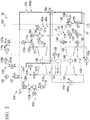
- Fig. 1 is a diagram showing an example of a configuration of a multi-stage compressor system 1 according to the first embodiment of the present invention.
- the multi-stage compressor system 1 includes a multi-stage compressor 10, a first sensor 20a, a second sensor 20b, a control unit 30, and a notification unit 40.
- the multi-stage compressor 10 includes a first-stage compressor body 101, a last-stage compressor body 102, and a second-stage compressor body 103.
- the first-stage compressor body 101 is a first-stage compressor body of the multi-stage compressor 10.
- the first-stage compressor body 101 takes in a gas and generates a compressed gas.
- the last-stage compressor body 102 is a compressor body of a last stage of the multi-stage compressor 10.
- the last-stage compressor body 102 takes in a gas compressed in a previous stage and generates a compressed gas.
- the second-stage compressor body 103 is connected to the first-stage compressor body 101 in series.
- the second-stage compressor body 103 takes in the gas compressed by the first-stage compressor body 101.
- the second-stage compressor body 103 compresses the taken in gas and discharges the compressed gas to a third-stage compressor body of a subsequent stage connected in series.
- a compressor body of a stage subsequent to the third-stage compressor body is connected in series.
- each compressor body of a stage subsequent to the third-stage compressor body similarly takes in a compressed gas, compresses the taken in gas, and outputs the compressed gas to a subsequent-stage compressor body.
- the first sensor 20a measures a flow rate of a gas taken in by the first-stage compressor body 101.
- the second sensor 20b measures a flow rate of a gas discharged by the last-stage compressor body 102.
- the control unit 30 compares a gas flow rate measured by the first sensor 20a with a gas flow rate measured by the second sensor 20b and determines whether two measurement values are the same within a predetermined error range.
- control unit 30 determines that the multi-stage compressor system 1 is normal.
- control unit 30 determines that a malfunction is occurring in the multi-stage compressor system 1.
- this determination is based on the fact that all the gas taken in by the first-stage compressor body 101 is discharged by passing through the second-stage compressor body 103, the subsequent-stage compressor body, and the last-stage compressor body 102.
- a measurement value of a flow rate of a gas taken in by the first-stage compressor body 101 is different from a measurement value of a flow rate of a gas discharged by passing through the second- and subsequent-stage compressor bodies including the last-stage compressor body 102
- a malfunction of the measuring instrument is first considered. When no malfunction is found in the measuring instrument, the gas between the first-stage compressor body 101 and the second- and subsequent-stage compressor bodies is likely to have been leaked. When the gas is leaked between the first-stage compressor body 101 and the second- and subsequent-stage compressor bodies, there is a possibility of a breakdown of a seal part of the compressor.
- the control unit 30 notifies the user that some malfunction might be occurring in the multi-stage compressor system 1 via the notification unit 40.
- the notification unit 40 is a display, a speaker, a vibration device, or the like.
- the notification unit 40 may display "Please confirm whether the measuring device is normal.” or "Gas is likely leaking.” or provide a notification by sound. Also, the notification unit 40 may cause the malfunction of the multi-stage compressor system 1 to be known by vibration.
- control unit 30 may stop flow rate deviation correction when it is determined that a malfunction is likely to have occurred in the multi-stage compressor system 1. Also, the control unit 30 may control a blowoff valve 108 to be opened to a fixed degree of opening in order to prevent a surge operation. In addition, the control unit 30 may stop the system.
- the control unit 30 compares the flow rates of gases taken in by the first-stage compressor body 101, which is measured by the first sensor 20a, with the flow rate of a gas discharged by the last-stage compressor body 102, which is measured by the second sensor 20b.
- the control unit 30 determines that there is a possibility of a sensor malfunction or gas leakage in the multi-stage compressor system 1.
- the control unit 30 notifies the user of a possibility of some occurring malfunction in the multi-stage compressor system 1 via the notification unit 40.
- the multi-stage compressor system 1 can detect a malfunction in the multi-stage compressor system 1 without making the measuring instrument redundant.
- Fig. 2 is a diagram showing an example of a configuration of a multi-stage compressor system 1a according to the second embodiment of the present invention.
- the multi-stage compressor system 1a includes a multi-stage compressor 10a and a compressor control device 200a (a control device).
- the multi-stage compressor 10a includes first-stage compressor bodies 101 (101a and 101b) arranged in series from an upstream side of a flow of a gas to a downstream side, a second-stage compressor body 103, and a last-stage compressor body 102.
- the first-stage compressor body 101 is formed of a pair including the first-stage compressor body 101a and the first-stage compressor body 101b.
- the first-stage compressor bodies 101 (101a and 101b), the second-stage compressor body 103, and the last-stage compressor body 102 are coupled via a shaft 106.
- the first-stage compressor bodies 101a and 101b are arranged to form a pair in parallel on the upstream side of the shaft 106.
- a motor 104 is connected to a middle portion of the shaft 106.
- Each compressor body and the motor 104 are connected to the shaft 106 via a gearbox 105.
- Supply lines 130a and 130b are pipes for supplying gases to the first-stage compressor bodies 101a and 101b.
- the supply line 130a is connected to an inlet of the first-stage compressor body 101a.
- the supply line 130b is connected to an inlet of the first-stage compressor body 101b.
- the first-stage compressor body 101a generates a compressed gas by taking in the gas via the supply line 130a and compressing the gas.
- the first-stage compressor body 101b generates a compressed gas by taking in the gas via the supply line 130b and compressing the gas.
- a first connection line 132 is a pipe for supplying the compressed gas generated by the first-stage compressor bodies 101a and 101b to the second-stage compressor body 103.
- the first connection line 132 is connected to an outlet of the first-stage compressor body 101a and an outlet of the first-stage compressor body 101b. Also, the first connection line 132 is connected to an inlet of the second-stage compressor body 103.
- the first connection line 132 includes a merging portion and the compressed gases discharged by the two first-stage compressor bodies 101a and 101b are merged in the merging portion. The first connection line 132 supplies the merged compressed gases to the second-stage compressor body 103.
- the second-stage compressor body 103 generates a compressed gas by further compressing the compressed gas taken in via the first connection line 132.
- a second connection line 133 is a pipe for supplying the compressed gas generated by the second-stage compressor body 103 to the last-stage compressor body 102.
- the second connection line 133 is connected to an outlet of the second-stage compressor body 103 and an inlet of the last-stage compressor body 102.
- the second connection line 133 supplies the compressed gas to the last-stage compressor body 102.
- the last-stage compressor body 102 generates a compressed gas by further compressing the compressed gas taken in via the second connection line 133.
- a discharge line 131 is a pipe for supplying the compressed gas generated by the last-stage compressor body 102 to a downstream process.
- the discharge line 131 is connected to an outlet of the last-stage compressor body 102 and an inlet of the downstream process.
- the discharge line 131 supplies the compressed gas to the downstream process.
- An inlet guide vane (hereinafter, IGV) 107a is provided in the supply line 130a around the inlet of the first-stage compressor body 101a.
- An IGV 107b is provided in the supply line 130b around the inlet of the first-stage compressor body 101b.
- the IGV 107a provided in the supply line 130a controls a flow rate of the gas flowing into the first-stage compressor body 101a.
- the IGV 107b provided in the supply line 130b controls the flow rate of the gas flowing into the first-stage compressor body 101b.
- the discharge line 131 around an outlet of the last-stage compressor body 102 is provided with the blowoff valve 108.
- the blowoff valve 108 When the compressor is a compressor in which the gas to be compressed is air, the blowoff valve 108 provided in the discharge line 131 discharges air into the atmosphere via a blowoff line 136.
- a recycle valve can be used.
- the blowoff valve 108 can return the gas to the supply line 130a via a recycle line by which the blowoff line 136 is connected to the supply line 130a.
- the blowoff valve 108 can return the gas to the supply line 130b via the recycle line in which the blowoff line 136 is connected to the supply line 130a.
- the IGV 107a, the IGV 107b, and the blowoff valve 108 control the outlet pressure of the compressor or avoid surging, its degree of opening is controlled.
- An inlet flow rate determination unit 114a is arranged at the supply line 130a.
- the inlet flow rate determination unit 114a determines the inlet gas flow rate of a gas flowing into the first-stage compressor body 101a and generates an inlet flow rate determination value.
- An inlet flow rate determination unit 114b is arranged at the supply line 130b. The inlet flow rate determination unit 114b determines an inlet gas flow rate of a gas flowing into the first-stage compressor body 101b and generates an inlet flow rate determination value.
- a post-merger pressure determination unit 110 is arranged in the downstream side of the merging portion of the first connection line 132.
- the post-merger pressure determination unit 110 generates a post-merger pressure determination value by determining a pressure after the merging of the gases flowing out of the first-stage compressor bodies 101a and 101b.
- a cooler 109a is arranged at the first connection line 132. The cooler 109a cools the gas flowing inside the first connection line 132.
- a cooler 109b is arranged at the second connection line 133.
- the cooler 109b cools the gas flowing inside the second connection line 133.
- An outlet pressure determination unit 111 is arranged at the discharge line 131.
- the outlet pressure determination unit 111 generates an outlet pressure determination value by determining the pressure of the gas flowing out of the last-stage compressor body 102.
- an outlet flow rate determination unit 115 is arranged at the discharge line 131.
- the outlet flow rate determination unit 115 generates an outlet flow rate determination value by determining the flow rate of the gas flowing out of the last-stage compressor body 102.
- Fig. 3 is a diagram showing an example of the configuration of the compressor control device 200a in the second embodiment of the present invention.
- the compressor control device 200a in the second embodiment of the present invention includes a control unit 30a, a notification unit 40, IGV opening degree control units 50 (50a and 50b), and a blowoff valve opening degree control unit 53.
- the IGV opening degree control unit 50a controls a degree of opening of the IGV 107a.
- the IGV opening degree control unit 50b controls a degree of opening of the IGV 107b. Configurations of the IGV opening degree control unit 50a and the IGV opening degree control unit 50b are identical.
- the IGV opening degree control unit 50a includes an IGV opening degree command value generation unit 51 and an IGV opening degree command value correction unit 52a.
- the IGV opening degree control unit 50b includes an IGV opening degree command value generation unit 51 and an IGV opening degree command value correction unit 52b.
- the IGV opening degree command value generation unit 51 is common between the IGV opening degree control unit 50a and the IGV opening degree control unit 50b.
- the IGV opening degree command value generation unit 51 generates and outputs an IGV opening degree command value indicating a degree of opening of the IGV 107a.
- the IGV opening degree command value generation unit 51 generates and outputs an IGV opening degree command value indicating a degree of opening of the IGV 107b.
- the IGV opening degree command value generation unit 51 includes a pressure controller 129 and a function generator 116.
- the IGV opening degree command value correction units 52a and 52b correct an IGV opening degree command value output by the IGV opening degree command value generation unit 51.
- the IGV opening degree command value correction unit 52a includes a flow rate indicator 125a which outputs an input inlet flow rate determination value as it is, a pressure indicator 126 which outputs an input post-merger pressure determination value as it is, and a function generator 117a which outputs an IGV opening degree correction value.
- the IGV opening degree command value correction unit 52b includes a flow rate indicator 125b which outputs an input inlet flow rate determination value as it is, the pressure indicator 126 which outputs an input post-merger pressure determination value as it is, and a function generator 117b which outputs an IGV opening degree correction value.
- the pressure indicator 126 is common between the IGV opening degree command value correction units 52a and 52b, but the present invention is not limited thereto.
- the blowoff valve opening degree control unit 53 controls a degree of opening of the blowoff valve 108.
- the blowoff valve opening degree control unit 53 includes upstream-side anti-surge control units 54 (54a and 54b), an outlet pressure control unit 55, a downstream-side anti-surge control unit 56, and a command value selection unit 112.
- anti-surge control is control for maintaining a flow rate at a fixed value or more in order to prevent the compressor from being damaged by so-called surging caused by a decrease in the flow rate in the compressor.
- the upstream-side anti-surge control unit 54a controls a degree of opening of the blowoff valve 108 in order to prevent surging from occurring in the first-stage compressor body 101a.
- the upstream-side anti-surge control unit 54b controls a degree of opening of the blowoff valve 108 in order to prevent surging from occurring in the first-stage compressor body 101b.
- configurations of the upstream-side anti-surge control unit 54a and the upstream-side anti-surge control unit 54b are identical.
- the upstream-side anti-surge control unit 54a includes a pressure indicator 126 which outputs an input post-merger outlet pressure determination value as it is, a function generator 118a which outputs an inlet flow rate target value, a flow rate indicator 125a which outputs an input inlet flow rate determination value as it is, and a flow rate controller 127a which outputs a blowoff valve opening degree command value on the basis of an inlet flow rate target value.
- the upstream-side anti-surge control unit 54b includes the pressure indicator 126 which outputs an input post-merger outlet pressure determination value as it is, a function generator 118b which outputs an inlet flow rate target value, a flow rate indicator 125b which outputs an input inlet flow rate determination value as it is, and a flow rate controller 127b which outputs a blowoff valve opening degree command value on the basis of an inlet flow rate target value.
- the pressure indicator 126 is common between the upstream-side anti-surge control unit 54a and the upstream-side anti-surge control unit 54b, the present invention is not limited thereto.
- the outlet pressure control unit 55 includes a pressure controller 129 which outputs an operation value for setting the input outlet pressure determination value to a setting value and a function generator 119 which outputs a blowoff valve opening degree command value.
- the downstream-side anti-surge control unit 56 includes a function generator 120 which outputs an outlet flow rate target value and a flow rate controller 128 which outputs a blowoff valve opening degree command value on the basis of the outlet flow rate target value.
- the IGV opening degree command value correction unit 52a includes a performance difference correction coefficient generation unit 124, an inlet flow rate target value generation unit 122, and a function generator 121a.
- the IGV opening degree command value correction unit 52b includes the performance difference correction coefficient generation unit 124, the inlet flow rate target value generation unit 122, and a function generator 121b.
- the performance difference correction coefficient generation unit 124 and the inlet flow rate target value generation unit 122 are common between the IGV opening degree command value correction unit 52a and the IGV opening degree command value correction unit 52b.
- the performance difference correction coefficient generation unit 124 generates and outputs a performance difference correction coefficient for correcting a performance difference between the two first-stage compressor bodies 101a and 101b.
- the performance difference correction coefficient and the inlet flow rate determination values in the first-stage compressor bodies 101a and 101b are input to the inlet flow rate target value generation unit 122 and inlet flow rate target values are generated for the first-stage compressor bodies 101a and 101b.
- the inlet flow rate target values are input to the corresponding function generators 121 a and 121b.
- the function generator 121a is provided in correspondence with a command value selection unit 113a.
- the function generator 121b is provided in correspondence with a command value selection unit 113b.
- the inlet flow rate target value and the inlet flow rate determination value output from the corresponding flow rate indicator 125a are input to the function generator 121 a.
- the inlet flow rate target value and the inlet flow rate determination value output from the corresponding flow rate indicator 125b are input to the function generator 121b.
- Function generators 121 (121a and 121b) generate and output IGV opening degree command correction values in proportion to a difference between the inlet flow rate target value and the inlet flow rate determination value.
- the function generators 121 (121a and 121b) may consider the integration of the difference between the inlet flow rate target value and the inlet flow rate determination value and generate and output the IGV opening degree command correction value.
- the control unit 30a inputs an inlet flow rate determination value corresponding to the inlet flow rate determination unit 114a from the flow rate indicator 125 a, an inlet flow rate determination value corresponding to the inlet flow rate determination unit 114b from the flow rate indicator 125b, and an output flow rate determination value of the outlet flow rate determination unit 115.
- the control unit 30a determines whether a malfunction is present in the multi-stage compressor system 1a on the basis of the inlet flow rate determination values and the output flow rate determination value.
- the control unit 30a inputs the inlet flow rate determination value corresponding to the inlet flow rate determination unit 114a from the flow rate indicator 125 a, the inlet flow rate determination value corresponding to the inlet flow rate determination unit 114b from the flow rate indicator 125b, and an output flow rate determination value of the outlet flow rate determination unit 115.
- the control unit 30a designates the inlet flow rate determination value input from the flow rate indicator 125a as FI11.
- the control unit 30a designates the inlet flow rate determination value input from the flow rate indicator 125b as FI12.
- the control unit 30a designates the output flow rate determination value input from the outlet flow rate determination unit 115 as FC3.
- the control unit 30a determines whether an absolute value of (FI11+FI12-FC3) is greater than or equal to a predetermined reference value.
- This reference value is a value determined in consideration of a flow rate response delay or a gas leakage amount of a normal operation time, a drain flow rate in a compressor intercooler, or the like.
- the control unit 30a determines that the multi-stage compressor system 1a is normal when the absolute value of (FI11+FI12-FC3) is less than the predetermined reference value.
- the control unit 30a determines that a malfunction is occurring in the multi-stage compressor system 1a. In this case, the control unit 30a notifies the user that some malfunction is likely occurring in the multi-stage compressor system 1a via the notification unit 40.
- the notification unit 40 is a display, a speaker, a vibration device, or the like. The notification unit 40 may display "Please confirm whether the measuring device is normal.” or "Gas is likely leaking.” or provide a notification by sound. Also, the notification unit 40 may cause the malfunction of the multi-stage compressor system 1a to be known by vibration.
- control unit 30a may stop flow rate deviation correction when it is determined that a malfunction has likely occurred in the multi-stage compressor system 1a. Also, the control unit 30a may control the blowoff valve 108 to be opened to a fixed degree of opening in order to prevent a surge operation. In addition, the control unit 30a may stop the system.
- control unit 30a compares the flow rates of gases taken in by the first-stage compressor bodies 101a and 101b, which are measured by the inlet flow rate determination units 114a and 114b (the first sensor), with the flow rate of a gas discharged by the last-stage compressor body 102, which is measured by the outlet flow rate determination unit 115 (the second sensor).
- the control unit 30a determines that there is a possibility of a malfunction of the determination unit or gas leakage in the multi-stage compressor system 1a.
- the control unit 30a notifies the user of a possibility of some occurring malfunction in the multi-stage compressor system 1a via the notification unit 40.
- the multi-stage compressor system 1a can detect a malfunction in the multi-stage compressor system 1a without making the measuring instrument redundant.
- Fig. 4 is a diagram showing an example of a configuration of a multi-stage compressor system 1b according to the third embodiment of the present invention.
- the multi-stage compressor system according to the third embodiment 1b includes a multi-stage compressor 10a and a compressor control device 200b (a control device).
- the multi-stage compressor system 1b is a system in which inlet pressure determination units 134 (134a and 134b), inlet temperature determination units 135 (135a and 135b), pressure indicators 136a, 136b, and 136c, and temperature indicators 137 (137a, 137b, and 137c), an outlet pressure determination unit 138, an outlet temperature determination unit 139, and a flow rate indicator 140 are added to the multi-stage compressor system 1a according to the second embodiment.
- the inlet pressure determination unit 134a generates an inlet pressure determination value by determining the pressure of the gas flowing into the first-stage compressor body 101a.
- the pressure indicator 136a outputs an inlet pressure determination value input from the inlet pressure determination unit 134a to the flow rate indicator 125a.
- the inlet temperature determination unit 135a generates an inlet temperature determination value by determining the temperature of a gas flowing into the first-stage compressor body 101a.
- the temperature indicator 137a outputs the inlet temperature determination value input from the inlet temperature determination unit 135a to the flow rate indicator 125a.
- the flow rate indicator 125 a corrects a flow rate determination value on the basis of the input inlet pressure determination value and the input inlet temperature determination value.
- the inlet pressure determination unit 134b generates an inlet pressure determination value by determining the pressure of a gas flowing into the first-stage compressor body 101b.
- the pressure indicator 136b outputs the inlet pressure determination value input from the inlet pressure determination unit 134b to the flow rate indicator 125b.
- the inlet temperature determination unit 135b generates an inlet temperature determination value by determining the temperature of a gas flowing into the first-stage compressor body 101b.
- the temperature indicator 137b outputs the inlet temperature determination value input from the inlet temperature determination unit 135b to the flow rate indicator 125b.
- the flow rate indicator 125b corrects a flow rate determination value on the basis of the input inlet pressure determination value and the input inlet temperature determination value.
- the outlet pressure determination unit 138 generates an outlet pressure determination value by determining the pressure of a gas flowing out of the last-stage compressor body 102.
- the pressure indicator 136c outputs an outlet pressure determination value output from the outlet pressure determination unit 138 to the flow rate indicator 140.
- the outlet temperature determination unit 139 generates an outlet temperature determination value by determining the temperature of the gas flowing out of the last-stage compressor body 102.
- the temperature indicator 137c outputs the outlet temperature determination value output from the outlet temperature determination unit 139 to the flow rate indicator 140.
- the flow rate indicator 140 corrects a flow rate determination value on the basis of the input outlet pressure determination value and the input outlet temperature determination value.
- the control unit 30b inputs an inlet flow rate determination value corresponding to the inlet flow rate determination unit 114a from the flow rate indicator 125 a, an inlet flow rate determination value corresponding to the inlet flow rate determination unit 114b from the flow rate indicator 125b, and an outlet flow rate determination value from the flow rate indicator 140.
- the control unit 30b designates the inlet flow rate determination value input from the flow rate indicator 125a as FI11c.
- the control unit 30b designates the inlet flow rate determination value input from the flow rate indicator 125b as F112c.
- the control unit 30b designates the output flow rate determination value input from the flow rate indicator 140 as FC3c.
- the control unit 30b determines whether an absolute value of (FI11c+FI12c-FC3c) is greater than or equal to a predetermined reference value.
- This reference value is a value determined in consideration of a flow rate response delay or a gas leakage amount of a normal operation time, a drain flow rate in a compressor intercooler, or the like.
- the control unit 30b determines that the multi-stage compressor system 1b is normal when the absolute value of (FI11c+FI12c-FC3c) is less than the predetermined reference value.
- the control unit 30b determines that a malfunction is occurring in the multi-stage compressor system 1b. In this case, the control unit 30b notifies the user that some malfunction is likely occurring in the multi-stage compressor system 1b via the notification unit 40.
- the notification unit 40 is a display, a speaker, a vibration device, or the like. The notification unit 40 may display "Please confirm whether the measuring device is normal.” or "Gas is likely leaking.” or provide a notification by sound. Also, the notification unit 40 may cause the malfunction of the multi-stage compressor system 1b to be known by vibration.
- control unit 30b may stop flow rate deviation correction when it is determined that a malfunction is likely occurring in the multi-stage compressor system 1b. Also, the control unit 30b may control the blowoff valve 108 to be opened to a fixed degree of opening in order to prevent a surge operation. In addition, the control unit 30b may stop the system.
- control unit 30b compares the flow rates of gases taken in by the first-stage compressor bodies 101a and 101b, which are measured by the inlet flow rate determination units 114a and 114b (the first sensor), with the flow rate of a gas discharged by the last-stage compressor body 102, which is measured by the outlet flow rate determination unit 115 (the second sensor).
- the control unit 30b determines that there is a possibility of a malfunction of the determination unit or gas leakage in the multi-stage compressor system 1b.
- the control unit 30b notifies the user of a possibility of some occurring malfunction in the multi-stage compressor system 1b via the notification unit 40.
- the multi-stage compressor system 1b can detect a malfunction in the multi-stage compressor system 1b without making the measuring instrument redundant.
- the control unit 30b determines that there is a possibility of a malfunction of the determination unit or gas leakage in the multi-stage compressor system 1b using a corrected gas flow rate on the basis of a measurement value of a pressure or a temperature in addition to the control unit 30a in the multi-stage compressor system 1a.
- control unit 30b can make a more accurate determination.
- a flow rate is corrected on the basis of results of measuring a pressure and a temperature in the above-described example
- the present invention is not limited thereto.
- a molecular weight of a gas may be measured and the flow rate may be corrected on the basis of the molecular weight.
- Fig. 5 is a diagram showing an example of a configuration of a multi-stage compressor system 1c according to the fourth embodiment of the present invention.
- the multi-stage compressor system 1c includes a multi-stage compressor 10a and a compressor control device 200c.
- the multi-stage compressor system 1c according to the fourth embodiment is a system in which drain flow rate meters 141 (141a and 141b) and drain valves 142 (142a and 142b) are added to the multi-stage compressor system 1a according to the second embodiment.
- the drain flow rates during cooling by the coolers 109a and 109b are measured from the drain flow rate meters 141 (141a and 141b) or the flow rate is estimated on the basis of degrees of opening of the drain valves 142 (142a and 142b).
- correspondence relationships between drain flow rates and degrees of opening of the valves are pre-acquired by experiments and the like and recorded in a storage unit.
- the drain flow rate is estimated on the basis of the correspondence relationships.
- the control unit 30c inputs an inlet flow rate determination value corresponding to the inlet flow rate determination unit 114a from the flow rate indicator 125 a, an inlet flow rate determination value corresponding to the inlet flow rate determination unit 114b from the flow rate indicator 125b, and an outlet flow rate determination value of the outlet flow rate determination unit 115.
- the control unit 30c designates the inlet flow rate determination value input from the flow rate indicator 125a as FI11.
- the control unit 30c designates the inlet flow rate determination value input from the flow rate indicator 125b as FI12.
- the control unit 30c designates the output flow rate determination value input from the outlet flow rate determination unit 115 as FC3.
- the control unit 30c designates a drain flow rate sum input from the drain flow rate meter 141 or the drain valve 142 as ⁇ FL.
- the control unit 30c determines whether an absolute value of (FI11+FI12-FC3- ⁇ FL) is greater than or equal to a predetermined reference value.
- This reference value is a value determined in consideration of a flow rate response delay or a gas leakage amount of a normal operation time.
- the control unit 30c determines that the multi-stage compressor system 1c is normal when the absolute value of (FI11+FI12-FC3- ⁇ FL) is less than the predetermined reference value.
- the control unit 30c determines that a malfunction is occurring in the multi-stage compressor system 1c. In this case, the control unit 30c notifies the user that some malfunction is likely occurring in the multi-stage compressor system 1c via the notification unit 40.
- the notification unit 40 is a display, a speaker, a vibration device, or the like. The notification unit 40 may display "Please confirm whether the measuring device is normal.” or "Gas is likely leaking.” or provide a notification by sound. Also, the notification unit 40 may cause the malfunction of the multi-stage compressor system 1c to be known by vibration.
- control unit 30c may stop flow rate deviation correction when it is determined that a malfunction is likely occurring in the multi-stage compressor system 1c. Also, the control unit 30c may control the blowoff valve 108 to be opened to a fixed degree of opening in order to prevent a surge operation. In addition, the control unit 30c may stop the system.
- the drain flow rate may be estimated from relationships between input gas conditions (a temperature, a pressure, a humidity, etc.) and operation conditions (a temperature and a pressure).
- control unit 30c compares the flow rates of gases taken in by the first-stage compressor bodies 101a and 101b, which are measured by the inlet flow rate determination units 114a and 114b (the first sensor), with the flow rate of a gas discharged by the last-stage compressor body 102, which is measured by the outlet flow rate determination unit 115 (the second sensor).
- the control unit 30c determines that there is a possibility of a malfunction of the determination unit or gas leakage in the multi-stage compressor system 1c.
- the control unit 30c notifies the user of a possibility of some occurring malfunction in the multi-stage compressor system 1c via the notification unit 40.
- the multi-stage compressor system 1c can detect a malfunction in the multi-stage compressor system 1c without making the measuring instrument redundant.
- a flow rate is corrected on the basis of results of measuring a pressure and a temperature in the above-described example
- the present invention is not limited thereto.
- a molecular weight of a gas may be measured and the flow rate may be corrected on the basis of the molecular weight.
- control unit 30c determines that there is a possibility of a malfunction of the determination unit or gas leakage in the multi-stage compressor system 1 c using a drain flow rate in addition to the control unit 30a in the multi-stage compressor system 1a.
- control unit 30c can make a more accurate determination.
- control unit may compare measurement values in compressor bodies of arbitrary different stages. In this case, the possibility of a malfunction of a measuring instrument used in measurement and the possibility of gas leakage between compressor bodies of two different stages are determined.
- the above-described multi-stage compressor system 1 internally includes a computer system.
- Each process described above may be stored in a computer-readable recording medium in the form of a program.
- the above-described process is performed by the computer reading and executing the program.
- the computer-readable recording medium may be a magnetic disk, a magneto-optical disc, a compact disc read-only memory (CD-ROM), a digital versatile disc-read only memory (DVD-ROM), a semiconductor memory, or the like.
- the computer program may be distributed to the computer through a communication line, and the computer receiving the distributed program may execute the program.
- the above-described program may be a program for implementing some of the above-described functions. Further, the above-described program may be a program, i.e., a so-called differential file (differential program), capable of implementing the above-described function in combination with a program already recorded on the computer system.
- a program i.e., a so-called differential file (differential program), capable of implementing the above-described function in combination with a program already recorded on the computer system.
- the control device According to the multi-stage compression system, the control device, the malfunction determination method, and the program described above, it is possible to detect a malfunction in a multi-stage compressor system without making a measuring instrument redundant.
Landscapes
- Engineering & Computer Science (AREA)
- Mechanical Engineering (AREA)
- General Engineering & Computer Science (AREA)
- Control Of Positive-Displacement Air Blowers (AREA)
- Control Of Positive-Displacement Pumps (AREA)
Abstract
Description
- The present invention relates to a multi-stage compressor system, a control device, a malfunction determination method, and a program.
- Priority is claimed on Japanese Patent Application No.
2014-136051, filed July 1, 2014 - A compressor which compresses gases and supplies the compressed gases to machines or the like connected to a downstream side of a gas system is known. As this compressor, there is a compressor in which a gas flow rate for a compressor body is adjusted by arranging an inlet guide vane (IGV) at an upstream side and adjusting the degree of opening of the IGV.
- In
Patent Document 1, technology of appropriately controlling a degree of opening of the IGV and performing an optimum operation even when a performance difference occurs between two first-stage compressor bodies among a plurality of compressor bodies is disclosed as related technology. - [Patent Document 1]
Japanese Unexamined Patent Application, First Publication No.2013-170573 - By the way, in a multi-stage compressor as disclosed in
Patent Document 1 when a flow rate meter provided in a first compressor is in an abnormal state and a result of measuring a gas flow rate higher than an actual gas flow rate is shown, an operation is performed at a low gas flow rate by correcting flow rate deviation on the basis of a result of erroneously measuring the gas flow rate. Thus, it is likely to be in a surge state. In this case, because the flow rate meter is in the abnormal state, anti-surge control for preventing the surge state using the flow rate meter is also likely not to be normally operated. - In addition, when a phenomenon in which an amount of leakage of a gas is increased by the breakdown or the like of the seal part occurs in the multi-stage compressor as disclosed in
Patent Document 1, the leakage of the gas is unlikely to be detected. - Also, a method based on redundancy or the like is considered to detect a malfunction of a measuring instrument such as a flow rate meter. However, when the method based on redundancy is used, the cost is likely to increase.
- Thus, technology capable of detecting a malfunction in the multi-stage compressor system without making a measuring instrument redundant is required.
- The present invention provides a multi-stage compressor system, a control device, a malfunction determination method, and a program capable of solving the above-described problem.
- According to a first aspect of the present invention, a multi-stage compressor system is a system of a multi-stage compressor in which compressors are connected in series in a plurality of stages, the multi-stage compressor system including: a control unit configured to determine whether a malfunction is present in the system by comparing a suction flow rate of a first-stage compressor measured by a first sensor with a downstream flow rate from an outlet of the multi-stage compressor measured by a second sensor.
- According to a second aspect of the present invention, in the multi-stage compressor system, the multi-stage compressor includes a pair of first-stage compressors and subsequent-stage compressors, wherein the subsequent-stage compressors serially connected to the first-stage compressors compress fluids compressed by the pair of first-stage compressors.
- According to a third aspect of the present invention, in the multi-stage compressor system, a measurement value of each of the first sensor and the second sensor is corrected according to at least one of a temperature of a fluid, a pressure of the fluid, and a molecular weight of the fluid in which the first sensor and the second sensor measure.
- According to a fourth aspect of the present invention, in the multi-stage compressor system, a third sensor configured to measure an amount of drainage downstream generated from a compressed fluid from an outlet of the first-stage compressor is provided, and measurement values of the first sensor and the second sensor are corrected according to the amount of drainage measured by the third sensor.
- According to a fifth aspect of the present invention, in the multi-stage compressor system, a pressure of a fluid is measured at an upstream side of the first sensor and a temperature of the fluid is measured at a downstream side of the first sensor.
- According to a sixth aspect of the present invention, a control device is a control device for a multi-stage compressor in which compressors are connected in series in a plurality of stages, the control device including: a control unit configured to determine whether a malfunction is present in the system by comparing a suction flow rate of a first-stage compressor measured by a first sensor with a downstream flow rate from an outlet of the multi-stage compressor measured by a second sensor.
- According to a seventh aspect of the present invention, in the control device, the multi-stage compressor includes a pair of first-stage compressors and subsequent-stage compressors, wherein the subsequent-stage compressors serially connected to the first-stage compressors compress fluids compressed by the pair of first-stage compressors.
- According to an eighth aspect of the present invention, in the control device, a measurement value of each of the first sensor and the second sensor is corrected according to at least one of a measured temperature of a fluid, a measured pressure of the fluid, and a measured molecular weight of the fluid around the sensor.
- According to a ninth aspect of the present invention, in the control device, a third sensor configured to measure an amount of drainage downstream generated from a compressed fluid from an outlet of the first-stage compressor is provided, and measurement values of the first sensor and the second sensor are corrected according to the amount of drainage measured by the third sensor.
- According to a tenth aspect of the present invention, in the control device, a pressure of a fluid is measured at an upstream side of the first sensor and a temperature of the fluid is measured at a downstream side of the first sensor.
- According to an eleventh aspect of the present invention, a malfunction determination method is a malfunction determination method for use in a system of a multi-stage compressor in which compressors are connected in series in a plurality of stages, the malfunction determination method including: determining, by a control unit, whether a malfunction is present in the system by comparing a suction flow rate of a first-stage compressor measured by a first sensor with a downstream flow rate from an outlet of the multi-stage compressor measured by a second sensor.
- According to a twelfth aspect of the present invention, in the malfunction determination method, the multi-stage compressor includes a pair of first-stage compressors and subsequent-stage compressors, wherein the subsequent-stage compressors serially connected to the first-stage compressors compress fluids compressed by the pair of first-stage compressors.
- According to a thirteenth aspect of the present invention, in the malfunction determination method, a measurement value of each of the first sensor and the second sensor is corrected according to at least one of a temperature of a fluid, a pressure of the fluid, and a molecular weight of the fluid in which the first sensor and the second sensor measure.
- According to a fourteenth aspect of the present invention, in the malfunction determination method, a third sensor configured to measure an amount of drainage downstream generated from a compressed fluid from an outlet of the first-stage compressor is provided, and measurement values of the first sensor and the second sensor are corrected according to the amount of drainage measured by the third sensor.
- According to a fifteenth aspect of the present invention, in the malfunction determination method, a pressure of a fluid is measured at an upstream side of the first sensor and the temperature of the fluid is measured at a downstream side of the first sensor.
- According to a sixteenth aspect of the present invention, a program is a program configured to cause a computer of a control device for controlling a multi-stage compressor in which compressors are connected in series in a plurality of stages to function as: a control means configured to determine whether a malfunction is present in the system by comparing a suction flow rate of a first-stage compressor measured by a first sensor with a downstream flow rate from an outlet of the multi-stage compressor measured by a second sensor.
- According to a seventeenth aspect of the present invention, the program causes the computer to function as: a means configured to correct a measurement value of each of the first sensor and the second sensor according to at least one of a measured temperature of a fluid, a measured pressure of the fluid, and a measured molecular weight of the fluid around the sensor.
- According to an eighteenth aspect of the present invention, the program causes the computer to function as: a means configured to correct measurement values of the first sensor and the second sensor according to the amount of drainage measured by a third sensor configured to measure an amount of drainage downstream generated from a compressed fluid from an outlet of the first-stage compressor.
- According to the multi-stage compression system, the control device, the malfunction determination method, and the program described above, it is possible to detect a malfunction in a multi-stage compressor system without making a measuring instrument redundant.
-
-
Fig. 1 is a diagram showing an example of a configuration of a multi-stage compressor system according to a first embodiment of the present invention. -
Fig. 2 is a diagram showing an example of a configuration of a multi-stage compressor system according to a second embodiment of the present invention. -
Fig. 3 is a diagram showing an example of a configuration of a compressor control device in the present embodiment. -
Fig. 4 is a diagram showing an example of a configuration of a multi-stage compressor system according to a third embodiment of the present invention. -
Fig. 5 is a diagram showing an example of a configuration of a multi-stage compressor system according to a fourth embodiment of the present invention. -
Fig. 1 is a diagram showing an example of a configuration of amulti-stage compressor system 1 according to the first embodiment of the present invention. - As shown in
Fig. 1 , themulti-stage compressor system 1 according to the first embodiment includes amulti-stage compressor 10, afirst sensor 20a, asecond sensor 20b, acontrol unit 30, and anotification unit 40. - The
multi-stage compressor 10 includes a first-stage compressor body 101, a last-stage compressor body 102, and a second-stage compressor body 103. - The first-
stage compressor body 101 is a first-stage compressor body of themulti-stage compressor 10. The first-stage compressor body 101 takes in a gas and generates a compressed gas. - The last-
stage compressor body 102 is a compressor body of a last stage of themulti-stage compressor 10. The last-stage compressor body 102 takes in a gas compressed in a previous stage and generates a compressed gas. - The second-
stage compressor body 103 is connected to the first-stage compressor body 101 in series. The second-stage compressor body 103 takes in the gas compressed by the first-stage compressor body 101. The second-stage compressor body 103 compresses the taken in gas and discharges the compressed gas to a third-stage compressor body of a subsequent stage connected in series. Likewise, a compressor body of a stage subsequent to the third-stage compressor body is connected in series. Also, each compressor body of a stage subsequent to the third-stage compressor body similarly takes in a compressed gas, compresses the taken in gas, and outputs the compressed gas to a subsequent-stage compressor body. - The
first sensor 20a measures a flow rate of a gas taken in by the first-stage compressor body 101. - The
second sensor 20b measures a flow rate of a gas discharged by the last-stage compressor body 102. - The
control unit 30 compares a gas flow rate measured by thefirst sensor 20a with a gas flow rate measured by thesecond sensor 20b and determines whether two measurement values are the same within a predetermined error range. - When it is determined that the two measurement values are the same within the predetermined error range, the
control unit 30 determines that themulti-stage compressor system 1 is normal. - Also, when it is determined that the two measurement values are not the same within the predetermined error range, the
control unit 30 determines that a malfunction is occurring in themulti-stage compressor system 1. - Also, when the
multi-stage compressor system 1 is normal, this determination is based on the fact that all the gas taken in by the first-stage compressor body 101 is discharged by passing through the second-stage compressor body 103, the subsequent-stage compressor body, and the last-stage compressor body 102. When a measurement value of a flow rate of a gas taken in by the first-stage compressor body 101 is different from a measurement value of a flow rate of a gas discharged by passing through the second- and subsequent-stage compressor bodies including the last-stage compressor body 102, a malfunction of the measuring instrument is first considered. When no malfunction is found in the measuring instrument, the gas between the first-stage compressor body 101 and the second- and subsequent-stage compressor bodies is likely to have been leaked. When the gas is leaked between the first-stage compressor body 101 and the second- and subsequent-stage compressor bodies, there is a possibility of a breakdown of a seal part of the compressor. - When a flow rate measurement result from the
first sensor 20a and a flow rate measurement result from thesecond sensor 20b are different, thecontrol unit 30 notifies the user that some malfunction might be occurring in themulti-stage compressor system 1 via thenotification unit 40. For example, thenotification unit 40 is a display, a speaker, a vibration device, or the like. Thenotification unit 40 may display "Please confirm whether the measuring device is normal." or "Gas is likely leaking." or provide a notification by sound. Also, thenotification unit 40 may cause the malfunction of themulti-stage compressor system 1 to be known by vibration. - Also, the
control unit 30 may stop flow rate deviation correction when it is determined that a malfunction is likely to have occurred in themulti-stage compressor system 1. Also, thecontrol unit 30 may control ablowoff valve 108 to be opened to a fixed degree of opening in order to prevent a surge operation. In addition, thecontrol unit 30 may stop the system. - As described above, in the
multi-stage compressor system 1, thecontrol unit 30 compares the flow rates of gases taken in by the first-stage compressor body 101, which is measured by thefirst sensor 20a, with the flow rate of a gas discharged by the last-stage compressor body 102, which is measured by thesecond sensor 20b. When the flow rates of gases taken in by the first-stage compressor body 101, which is measured by thefirst sensor 20a, are different from the flow rate of a gas discharged by the last-stage compressor body 102, which is measured by thesecond sensor 20b, thecontrol unit 30 determines that there is a possibility of a sensor malfunction or gas leakage in themulti-stage compressor system 1. Thecontrol unit 30 notifies the user of a possibility of some occurring malfunction in themulti-stage compressor system 1 via thenotification unit 40. - Thus, the
multi-stage compressor system 1 can detect a malfunction in themulti-stage compressor system 1 without making the measuring instrument redundant. -
Fig. 2 is a diagram showing an example of a configuration of a multi-stage compressor system 1a according to the second embodiment of the present invention. - The multi-stage compressor system 1a according to the second embodiment includes a
multi-stage compressor 10a and acompressor control device 200a (a control device). - The
multi-stage compressor 10a includes first-stage compressor bodies 101 (101a and 101b) arranged in series from an upstream side of a flow of a gas to a downstream side, a second-stage compressor body 103, and a last-stage compressor body 102. The first-stage compressor body 101 is formed of a pair including the first-stage compressor body 101a and the first-stage compressor body 101b. - The first-stage compressor bodies 101 (101a and 101b), the second-
stage compressor body 103, and the last-stage compressor body 102 are coupled via ashaft 106. The first-stage compressor bodies shaft 106. On the downstream side of theshaft 106, the second-stage compressor body 103 and the last-stage compressor body 102 are arranged in parallel. Amotor 104 is connected to a middle portion of theshaft 106. Each compressor body and themotor 104 are connected to theshaft 106 via agearbox 105. -
Supply lines stage compressor bodies supply line 130a is connected to an inlet of the first-stage compressor body 101a. Also, thesupply line 130b is connected to an inlet of the first-stage compressor body 101b. The first-stage compressor body 101a generates a compressed gas by taking in the gas via thesupply line 130a and compressing the gas. The first-stage compressor body 101b generates a compressed gas by taking in the gas via thesupply line 130b and compressing the gas. - A
first connection line 132 is a pipe for supplying the compressed gas generated by the first-stage compressor bodies stage compressor body 103. Thefirst connection line 132 is connected to an outlet of the first-stage compressor body 101a and an outlet of the first-stage compressor body 101b. Also, thefirst connection line 132 is connected to an inlet of the second-stage compressor body 103. Thefirst connection line 132 includes a merging portion and the compressed gases discharged by the two first-stage compressor bodies first connection line 132 supplies the merged compressed gases to the second-stage compressor body 103. - The second-
stage compressor body 103 generates a compressed gas by further compressing the compressed gas taken in via thefirst connection line 132. Asecond connection line 133 is a pipe for supplying the compressed gas generated by the second-stage compressor body 103 to the last-stage compressor body 102. Thesecond connection line 133 is connected to an outlet of the second-stage compressor body 103 and an inlet of the last-stage compressor body 102. Thesecond connection line 133 supplies the compressed gas to the last-stage compressor body 102. - The last-
stage compressor body 102 generates a compressed gas by further compressing the compressed gas taken in via thesecond connection line 133. Adischarge line 131 is a pipe for supplying the compressed gas generated by the last-stage compressor body 102 to a downstream process. Thedischarge line 131 is connected to an outlet of the last-stage compressor body 102 and an inlet of the downstream process. Thedischarge line 131 supplies the compressed gas to the downstream process. - An inlet guide vane (hereinafter, IGV) 107a is provided in the
supply line 130a around the inlet of the first-stage compressor body 101a. AnIGV 107b is provided in thesupply line 130b around the inlet of the first-stage compressor body 101b. TheIGV 107a provided in thesupply line 130a controls a flow rate of the gas flowing into the first-stage compressor body 101a. TheIGV 107b provided in thesupply line 130b controls the flow rate of the gas flowing into the first-stage compressor body 101b. - The
discharge line 131 around an outlet of the last-stage compressor body 102 is provided with theblowoff valve 108. When the compressor is a compressor in which the gas to be compressed is air, theblowoff valve 108 provided in thedischarge line 131 discharges air into the atmosphere via ablowoff line 136. Also, when the gas is nitrogen or the like, a recycle valve can be used. In this case, theblowoff valve 108 can return the gas to thesupply line 130a via a recycle line by which theblowoff line 136 is connected to thesupply line 130a. Also, theblowoff valve 108 can return the gas to thesupply line 130b via the recycle line in which theblowoff line 136 is connected to thesupply line 130a. - Because the
IGV 107a, theIGV 107b, and theblowoff valve 108 control the outlet pressure of the compressor or avoid surging, its degree of opening is controlled. - An inlet flow
rate determination unit 114a is arranged at thesupply line 130a. The inlet flowrate determination unit 114a determines the inlet gas flow rate of a gas flowing into the first-stage compressor body 101a and generates an inlet flow rate determination value. An inlet flowrate determination unit 114b is arranged at thesupply line 130b. The inlet flowrate determination unit 114b determines an inlet gas flow rate of a gas flowing into the first-stage compressor body 101b and generates an inlet flow rate determination value. - A post-merger
pressure determination unit 110 is arranged in the downstream side of the merging portion of thefirst connection line 132. The post-mergerpressure determination unit 110 generates a post-merger pressure determination value by determining a pressure after the merging of the gases flowing out of the first-stage compressor bodies first connection line 132. The cooler 109a cools the gas flowing inside thefirst connection line 132. - A cooler 109b is arranged at the
second connection line 133. The cooler 109b cools the gas flowing inside thesecond connection line 133. - An outlet pressure determination unit 111 is arranged at the
discharge line 131. The outlet pressure determination unit 111 generates an outlet pressure determination value by determining the pressure of the gas flowing out of the last-stage compressor body 102. Also, an outlet flowrate determination unit 115 is arranged at thedischarge line 131. The outlet flowrate determination unit 115 generates an outlet flow rate determination value by determining the flow rate of the gas flowing out of the last-stage compressor body 102. - Next, a configuration of the
compressor control device 200a in the second embodiment of the present invention will be described. -
Fig. 3 is a diagram showing an example of the configuration of thecompressor control device 200a in the second embodiment of the present invention. - The
compressor control device 200a in the second embodiment of the present invention includes acontrol unit 30a, anotification unit 40, IGV opening degree control units 50 (50a and 50b), and a blowoff valve openingdegree control unit 53. - The IGV opening
degree control unit 50a controls a degree of opening of theIGV 107a. The IGV openingdegree control unit 50b controls a degree of opening of theIGV 107b. Configurations of the IGV openingdegree control unit 50a and the IGV openingdegree control unit 50b are identical. - The IGV opening
degree control unit 50a includes an IGV opening degree commandvalue generation unit 51 and an IGV opening degree commandvalue correction unit 52a. The IGV openingdegree control unit 50b includes an IGV opening degree commandvalue generation unit 51 and an IGV opening degree commandvalue correction unit 52b. The IGV opening degree commandvalue generation unit 51 is common between the IGV openingdegree control unit 50a and the IGV openingdegree control unit 50b. - The IGV opening degree command
value generation unit 51 generates and outputs an IGV opening degree command value indicating a degree of opening of theIGV 107a. The IGV opening degree commandvalue generation unit 51 generates and outputs an IGV opening degree command value indicating a degree of opening of theIGV 107b. The IGV opening degree commandvalue generation unit 51 includes apressure controller 129 and afunction generator 116. - The IGV opening degree command
value correction units value generation unit 51. - The IGV opening degree command
value correction unit 52a includes aflow rate indicator 125a which outputs an input inlet flow rate determination value as it is, apressure indicator 126 which outputs an input post-merger pressure determination value as it is, and afunction generator 117a which outputs an IGV opening degree correction value. - The IGV opening degree command
value correction unit 52b includes aflow rate indicator 125b which outputs an input inlet flow rate determination value as it is, thepressure indicator 126 which outputs an input post-merger pressure determination value as it is, and afunction generator 117b which outputs an IGV opening degree correction value. - The
pressure indicator 126 is common between the IGV opening degree commandvalue correction units - The blowoff valve opening
degree control unit 53 controls a degree of opening of theblowoff valve 108. The blowoff valve openingdegree control unit 53 includes upstream-side anti-surge control units 54 (54a and 54b), an outletpressure control unit 55, a downstream-sideanti-surge control unit 56, and a commandvalue selection unit 112. - Here, anti-surge control is control for maintaining a flow rate at a fixed value or more in order to prevent the compressor from being damaged by so-called surging caused by a decrease in the flow rate in the compressor.
- The upstream-side
anti-surge control unit 54a controls a degree of opening of theblowoff valve 108 in order to prevent surging from occurring in the first-stage compressor body 101a. The upstream-sideanti-surge control unit 54b controls a degree of opening of theblowoff valve 108 in order to prevent surging from occurring in the first-stage compressor body 101b. Here, configurations of the upstream-sideanti-surge control unit 54a and the upstream-sideanti-surge control unit 54b are identical. - The upstream-side
anti-surge control unit 54a includes apressure indicator 126 which outputs an input post-merger outlet pressure determination value as it is, afunction generator 118a which outputs an inlet flow rate target value, aflow rate indicator 125a which outputs an input inlet flow rate determination value as it is, and aflow rate controller 127a which outputs a blowoff valve opening degree command value on the basis of an inlet flow rate target value. The upstream-sideanti-surge control unit 54b includes thepressure indicator 126 which outputs an input post-merger outlet pressure determination value as it is, afunction generator 118b which outputs an inlet flow rate target value, aflow rate indicator 125b which outputs an input inlet flow rate determination value as it is, and aflow rate controller 127b which outputs a blowoff valve opening degree command value on the basis of an inlet flow rate target value. - Also, although the
pressure indicator 126 is common between the upstream-sideanti-surge control unit 54a and the upstream-sideanti-surge control unit 54b, the present invention is not limited thereto. - The outlet
pressure control unit 55 includes apressure controller 129 which outputs an operation value for setting the input outlet pressure determination value to a setting value and afunction generator 119 which outputs a blowoff valve opening degree command value. - The downstream-side
anti-surge control unit 56 includes afunction generator 120 which outputs an outlet flow rate target value and aflow rate controller 128 which outputs a blowoff valve opening degree command value on the basis of the outlet flow rate target value. - Also, the IGV opening degree command
value correction unit 52a includes a performance difference correctioncoefficient generation unit 124, an inlet flow rate targetvalue generation unit 122, and afunction generator 121a. The IGV opening degree commandvalue correction unit 52b includes the performance difference correctioncoefficient generation unit 124, the inlet flow rate targetvalue generation unit 122, and afunction generator 121b. - The performance difference correction
coefficient generation unit 124 and the inlet flow rate targetvalue generation unit 122 are common between the IGV opening degree commandvalue correction unit 52a and the IGV opening degree commandvalue correction unit 52b. The performance difference correctioncoefficient generation unit 124 generates and outputs a performance difference correction coefficient for correcting a performance difference between the two first-stage compressor bodies stage compressor bodies value generation unit 122 and inlet flow rate target values are generated for the first-stage compressor bodies - The inlet flow rate target values are input to the
corresponding function generators function generator 121a is provided in correspondence with a commandvalue selection unit 113a. Thefunction generator 121b is provided in correspondence with a commandvalue selection unit 113b. - The inlet flow rate target value and the inlet flow rate determination value output from the corresponding
flow rate indicator 125a are input to thefunction generator 121 a. The inlet flow rate target value and the inlet flow rate determination value output from the correspondingflow rate indicator 125b are input to thefunction generator 121b. Function generators 121 (121a and 121b) generate and output IGV opening degree command correction values in proportion to a difference between the inlet flow rate target value and the inlet flow rate determination value. Here the function generators 121 (121a and 121b) may consider the integration of the difference between the inlet flow rate target value and the inlet flow rate determination value and generate and output the IGV opening degree command correction value. - The
control unit 30a inputs an inlet flow rate determination value corresponding to the inlet flowrate determination unit 114a from theflow rate indicator 125 a, an inlet flow rate determination value corresponding to the inlet flowrate determination unit 114b from theflow rate indicator 125b, and an output flow rate determination value of the outlet flowrate determination unit 115. Thecontrol unit 30a determines whether a malfunction is present in the multi-stage compressor system 1a on the basis of the inlet flow rate determination values and the output flow rate determination value. - Next, operations of the
control unit 30a and thenotification unit 40 provided in thecompressor control device 200a according to the second embodiment will be described. - The
control unit 30a inputs the inlet flow rate determination value corresponding to the inlet flowrate determination unit 114a from theflow rate indicator 125 a, the inlet flow rate determination value corresponding to the inlet flowrate determination unit 114b from theflow rate indicator 125b, and an output flow rate determination value of the outlet flowrate determination unit 115. Thecontrol unit 30a designates the inlet flow rate determination value input from theflow rate indicator 125a as FI11. Thecontrol unit 30a designates the inlet flow rate determination value input from theflow rate indicator 125b as FI12. Thecontrol unit 30a designates the output flow rate determination value input from the outlet flowrate determination unit 115 as FC3. Thecontrol unit 30a determines whether an absolute value of (FI11+FI12-FC3) is greater than or equal to a predetermined reference value. This reference value is a value determined in consideration of a flow rate response delay or a gas leakage amount of a normal operation time, a drain flow rate in a compressor intercooler, or the like. - The
control unit 30a determines that the multi-stage compressor system 1a is normal when the absolute value of (FI11+FI12-FC3) is less than the predetermined reference value. - Also, when the absolute value of (FI11+FI12-FC3) is greater than or equal to the predetermined reference value, the
control unit 30a determines that a malfunction is occurring in the multi-stage compressor system 1a. In this case, thecontrol unit 30a notifies the user that some malfunction is likely occurring in the multi-stage compressor system 1a via thenotification unit 40. For example, thenotification unit 40 is a display, a speaker, a vibration device, or the like. Thenotification unit 40 may display "Please confirm whether the measuring device is normal." or "Gas is likely leaking." or provide a notification by sound. Also, thenotification unit 40 may cause the malfunction of the multi-stage compressor system 1a to be known by vibration. - Also, the
control unit 30a may stop flow rate deviation correction when it is determined that a malfunction has likely occurred in the multi-stage compressor system 1a. Also, thecontrol unit 30a may control theblowoff valve 108 to be opened to a fixed degree of opening in order to prevent a surge operation. In addition, thecontrol unit 30a may stop the system. - As described above, in the multi-stage compressor system 1a, the
control unit 30a compares the flow rates of gases taken in by the first-stage compressor bodies rate determination units stage compressor body 102, which is measured by the outlet flow rate determination unit 115 (the second sensor). When the flow rates of gases taken in by the first-stage compressor bodies 101, which are measured by the inlet flowrate determination units stage compressor body 102, which is measured by the outlet flowrate determination unit 115, thecontrol unit 30a determines that there is a possibility of a malfunction of the determination unit or gas leakage in the multi-stage compressor system 1a. Thecontrol unit 30a notifies the user of a possibility of some occurring malfunction in the multi-stage compressor system 1a via thenotification unit 40. - Thus, the multi-stage compressor system 1a can detect a malfunction in the multi-stage compressor system 1a without making the measuring instrument redundant.
-
Fig. 4 is a diagram showing an example of a configuration of amulti-stage compressor system 1b according to the third embodiment of the present invention. - The multi-stage compressor system according to the
third embodiment 1b includes amulti-stage compressor 10a and acompressor control device 200b (a control device). - The
multi-stage compressor system 1b according to the third embodiment is a system in which inlet pressure determination units 134 (134a and 134b), inlet temperature determination units 135 (135a and 135b),pressure indicators temperature determination unit 139, and a flow rate indicator 140 are added to the multi-stage compressor system 1a according to the second embodiment. - Here, a difference of the
multi-stage compressor system 1b according to the third embodiment from the multi-stage compressor system 1a according to the second embodiment will be described. - The inlet
pressure determination unit 134a generates an inlet pressure determination value by determining the pressure of the gas flowing into the first-stage compressor body 101a. Thepressure indicator 136a outputs an inlet pressure determination value input from the inletpressure determination unit 134a to theflow rate indicator 125a. - The inlet temperature determination unit 135a generates an inlet temperature determination value by determining the temperature of a gas flowing into the first-
stage compressor body 101a. Thetemperature indicator 137a outputs the inlet temperature determination value input from the inlet temperature determination unit 135a to theflow rate indicator 125a. - The
flow rate indicator 125 a corrects a flow rate determination value on the basis of the input inlet pressure determination value and the input inlet temperature determination value. - The inlet
pressure determination unit 134b generates an inlet pressure determination value by determining the pressure of a gas flowing into the first-stage compressor body 101b. Thepressure indicator 136b outputs the inlet pressure determination value input from the inletpressure determination unit 134b to theflow rate indicator 125b. - The inlet temperature determination unit 135b generates an inlet temperature determination value by determining the temperature of a gas flowing into the first-
stage compressor body 101b. Thetemperature indicator 137b outputs the inlet temperature determination value input from the inlet temperature determination unit 135b to theflow rate indicator 125b. - The
flow rate indicator 125b corrects a flow rate determination value on the basis of the input inlet pressure determination value and the input inlet temperature determination value. - The outlet pressure determination unit 138 generates an outlet pressure determination value by determining the pressure of a gas flowing out of the last-
stage compressor body 102. Thepressure indicator 136c outputs an outlet pressure determination value output from the outlet pressure determination unit 138 to the flow rate indicator 140. - The outlet
temperature determination unit 139 generates an outlet temperature determination value by determining the temperature of the gas flowing out of the last-stage compressor body 102. Thetemperature indicator 137c outputs the outlet temperature determination value output from the outlettemperature determination unit 139 to the flow rate indicator 140. - The flow rate indicator 140 corrects a flow rate determination value on the basis of the input outlet pressure determination value and the input outlet temperature determination value.
- The
control unit 30b inputs an inlet flow rate determination value corresponding to the inlet flowrate determination unit 114a from theflow rate indicator 125 a, an inlet flow rate determination value corresponding to the inlet flowrate determination unit 114b from theflow rate indicator 125b, and an outlet flow rate determination value from the flow rate indicator 140. Thecontrol unit 30b designates the inlet flow rate determination value input from theflow rate indicator 125a as FI11c. Thecontrol unit 30b designates the inlet flow rate determination value input from theflow rate indicator 125b as F112c. Thecontrol unit 30b designates the output flow rate determination value input from the flow rate indicator 140 as FC3c. Thecontrol unit 30b determines whether an absolute value of (FI11c+FI12c-FC3c) is greater than or equal to a predetermined reference value. This reference value is a value determined in consideration of a flow rate response delay or a gas leakage amount of a normal operation time, a drain flow rate in a compressor intercooler, or the like. - The
control unit 30b determines that themulti-stage compressor system 1b is normal when the absolute value of (FI11c+FI12c-FC3c) is less than the predetermined reference value. - Also, when the absolute value of (FI11c+FI12c-FC3c) is greater than or equal to the predetermined reference value, the
control unit 30b determines that a malfunction is occurring in themulti-stage compressor system 1b. In this case, thecontrol unit 30b notifies the user that some malfunction is likely occurring in themulti-stage compressor system 1b via thenotification unit 40. For example, thenotification unit 40 is a display, a speaker, a vibration device, or the like. Thenotification unit 40 may display "Please confirm whether the measuring device is normal." or "Gas is likely leaking." or provide a notification by sound. Also, thenotification unit 40 may cause the malfunction of themulti-stage compressor system 1b to be known by vibration. - Also, the
control unit 30b may stop flow rate deviation correction when it is determined that a malfunction is likely occurring in themulti-stage compressor system 1b. Also, thecontrol unit 30b may control theblowoff valve 108 to be opened to a fixed degree of opening in order to prevent a surge operation. In addition, thecontrol unit 30b may stop the system. - As described above, in the
multi-stage compressor system 1b, thecontrol unit 30b compares the flow rates of gases taken in by the first-stage compressor bodies rate determination units stage compressor body 102, which is measured by the outlet flow rate determination unit 115 (the second sensor). When the flow rates of gases taken in by the first-stage compressor bodies 101, which are measured by the inlet flowrate determination units stage compressor body 102, which is measured by the outlet flowrate determination unit 115, thecontrol unit 30b determines that there is a possibility of a malfunction of the determination unit or gas leakage in themulti-stage compressor system 1b. Thecontrol unit 30b notifies the user of a possibility of some occurring malfunction in themulti-stage compressor system 1b via thenotification unit 40. - Thus, the
multi-stage compressor system 1b can detect a malfunction in themulti-stage compressor system 1b without making the measuring instrument redundant. - Also, as described above, in the
multi-stage compressor system 1b, thecontrol unit 30b determines that there is a possibility of a malfunction of the determination unit or gas leakage in themulti-stage compressor system 1b using a corrected gas flow rate on the basis of a measurement value of a pressure or a temperature in addition to thecontrol unit 30a in the multi-stage compressor system 1a. - Thereby, the
control unit 30b can make a more accurate determination. - Also, when the pressure and temperature are measured as in the above-described example, it is desirable to measure a pressure upstream and measure a temperature downstream. This is because the turbulence of a gas flow due to the temperature measurement instrument is likely to affect measurement of the pressure when the temperature measurement instrument is located upstream and a pressure is measured downstream.
- Also, although a flow rate is corrected on the basis of results of measuring a pressure and a temperature in the above-described example, the present invention is not limited thereto. A molecular weight of a gas may be measured and the flow rate may be corrected on the basis of the molecular weight. Thereby, it is possible to perform correction considering an influence by a gas other than the air and the
control unit 30b can make a more accurate determination. -
Fig. 5 is a diagram showing an example of a configuration of amulti-stage compressor system 1c according to the fourth embodiment of the present invention. - The
multi-stage compressor system 1c according to the fourth embodiment includes amulti-stage compressor 10a and acompressor control device 200c. - The
multi-stage compressor system 1c according to the fourth embodiment is a system in which drain flow rate meters 141 (141a and 141b) and drain valves 142 (142a and 142b) are added to the multi-stage compressor system 1a according to the second embodiment. - Here, a difference of the
multi-stage compressor system 1c according to the fourth embodiment from the multi-stage compressor system 1a according to the second embodiment will be described. - The drain flow rates during cooling by the
coolers - For example, correspondence relationships between drain flow rates and degrees of opening of the valves are pre-acquired by experiments and the like and recorded in a storage unit. The drain flow rate is estimated on the basis of the correspondence relationships.
- The
control unit 30c inputs an inlet flow rate determination value corresponding to the inlet flowrate determination unit 114a from theflow rate indicator 125 a, an inlet flow rate determination value corresponding to the inlet flowrate determination unit 114b from theflow rate indicator 125b, and an outlet flow rate determination value of the outlet flowrate determination unit 115. Thecontrol unit 30c designates the inlet flow rate determination value input from theflow rate indicator 125a as FI11. Thecontrol unit 30c designates the inlet flow rate determination value input from theflow rate indicator 125b as FI12. Thecontrol unit 30c designates the output flow rate determination value input from the outlet flowrate determination unit 115 as FC3. Thecontrol unit 30c designates a drain flow rate sum input from the drain flow rate meter 141 or the drain valve 142 as ΣFL. Thecontrol unit 30c determines whether an absolute value of (FI11+FI12-FC3-∑FL) is greater than or equal to a predetermined reference value. This reference value is a value determined in consideration of a flow rate response delay or a gas leakage amount of a normal operation time. - The
control unit 30c determines that themulti-stage compressor system 1c is normal when the absolute value of (FI11+FI12-FC3-∑FL) is less than the predetermined reference value. - Also, when the absolute value of (FI11+FI12-FC3-∑FL) is greater than or equal to the predetermined reference value, the
control unit 30c determines that a malfunction is occurring in themulti-stage compressor system 1c. In this case, thecontrol unit 30c notifies the user that some malfunction is likely occurring in themulti-stage compressor system 1c via thenotification unit 40. For example, thenotification unit 40 is a display, a speaker, a vibration device, or the like. Thenotification unit 40 may display "Please confirm whether the measuring device is normal." or "Gas is likely leaking." or provide a notification by sound. Also, thenotification unit 40 may cause the malfunction of themulti-stage compressor system 1c to be known by vibration. - Also, the
control unit 30c may stop flow rate deviation correction when it is determined that a malfunction is likely occurring in themulti-stage compressor system 1c. Also, thecontrol unit 30c may control theblowoff valve 108 to be opened to a fixed degree of opening in order to prevent a surge operation. In addition, thecontrol unit 30c may stop the system. - Also, the drain flow rate may be estimated from relationships between input gas conditions (a temperature, a pressure, a humidity, etc.) and operation conditions (a temperature and a pressure).
- As described above, in the
multi-stage compressor system 1c, thecontrol unit 30c compares the flow rates of gases taken in by the first-stage compressor bodies rate determination units stage compressor body 102, which is measured by the outlet flow rate determination unit 115 (the second sensor). When the flow rates of gases taken in by the first-stage compressor bodies 101, which are measured by the inlet flowrate determination units stage compressor body 102, which is measured by the outlet flowrate determination unit 115, thecontrol unit 30c determines that there is a possibility of a malfunction of the determination unit or gas leakage in themulti-stage compressor system 1c. Thecontrol unit 30c notifies the user of a possibility of some occurring malfunction in themulti-stage compressor system 1c via thenotification unit 40. - Thereby, the
multi-stage compressor system 1c can detect a malfunction in themulti-stage compressor system 1c without making the measuring instrument redundant. - Also, when the pressure and temperature are measured as in the above-described example, it is desirable to measure a pressure upstream and measure a temperature downstream. This is because the turbulence of a gas flow due to the temperature measurement instrument is likely to affect measurement of the pressure when the temperature measurement instrument is located upstream and a pressure is measured downstream.
- Also, although a flow rate is corrected on the basis of results of measuring a pressure and a temperature in the above-described example, the present invention is not limited thereto. A molecular weight of a gas may be measured and the flow rate may be corrected on the basis of the molecular weight. Thereby, it is possible to perform correction considering an influence by a gas other than the air and the
control unit 30c can make a more accurate determination. - Also, as described above, in the
multi-stage compressor system 1c, thecontrol unit 30c determines that there is a possibility of a malfunction of the determination unit or gas leakage in themulti-stage compressor system 1 c using a drain flow rate in addition to thecontrol unit 30a in the multi-stage compressor system 1a. - Thereby, the
control unit 30c can make a more accurate determination. - Also, although an example shown in the above-described embodiment is an example in which the gas flow rate of the last-
stage compressor body 102 is measured, the present invention is not limited thereto. The control unit may compare measurement values in compressor bodies of arbitrary different stages. In this case, the possibility of a malfunction of a measuring instrument used in measurement and the possibility of gas leakage between compressor bodies of two different stages are determined. - Also, an embodiment of the present invention has been described, but the above-described
multi-stage compressor system 1 internally includes a computer system. Each process described above may be stored in a computer-readable recording medium in the form of a program. The above-described process is performed by the computer reading and executing the program. Here, the computer-readable recording medium may be a magnetic disk, a magneto-optical disc, a compact disc read-only memory (CD-ROM), a digital versatile disc-read only memory (DVD-ROM), a semiconductor memory, or the like. In addition, the computer program may be distributed to the computer through a communication line, and the computer receiving the distributed program may execute the program. - Also, the above-described program may be a program for implementing some of the above-described functions. Further, the above-described program may be a program, i.e., a so-called differential file (differential program), capable of implementing the above-described function in combination with a program already recorded on the computer system.
- Although some embodiments of the present invention have been described, these embodiments have been proposed as examples and are not intended to limit the range of the invention. These embodiments can be executed in various other modes. Various omissions, replacements, and changes can be made in a range not departing from the scope of the invention.
- According to the multi-stage compression system, the control device, the malfunction determination method, and the program described above, it is possible to detect a malfunction in a multi-stage compressor system without making a measuring instrument redundant.
-
- 1, 1a, 1b, 1c
- Multi-stage compressor system
- 10, 10a
- Multi-stage compressor
- 20a
- First sensor
- 20b
- Second sensor
- 30, 30a, 30b, 30c
- Control unit
- 40
- Notification unit
- 50a, 50b
- Inlet guide vanes (IGV) opening degree control unit
- 51
- IGV opening degree command value generation unit
- 52a, 52bIGV
- opening degree command value correction unit
- 53
- Blowoff valve opening degree control unit
- 54a,
- 54bUpstream-side anti-surge control unit
- 55
- Outlet pressure control unit
- 56
- Downstream-side anti-surge control unit
- 101, 101a, 101b
- First-stage compressor
- 102
- Last-stage compressor
- 103
- Second-stage compressor
- 104
- Motor
- 105
- Gearbox
- 106
- Shaft
- 107a, 107b
- IGV
- 108
- Blowoffvalve
- 109a, 109b
- Cooler
- 110
- Post-merger pressure determination unit
- 111, 138
- Outlet pressure determination unit
- 112, 113a, 113b
- Command value selection unit
- 114a, 114b
- Inlet flow rate determination unit
- 115
- Outlet flow rate determination unit
- 116, 117a, 117b, 118a, 118b, 119, 120, 121a, 121b, 122
- Function generator
- 123a, 123b
- Correction cancellation signal generation unit
- 124
- Performance difference correction coefficient generation unit
- 125a, 125b, 140
- Flow rate indicator
- 126, 136a, 136b, 136c
- Pressure indicator
- 127a, 127b, 128
- Flow rate controller
- 129
- Pressure controller
- 130a, 130b
- Supply line
- 131
- Discharge line
- 132
- First connection line
- 133
- Second connection line
- 134a, 134b
- Inlet pressure determination unit
- 135a, 135b
- Inlet temperature determination unit
- 136
- Blowoff line
- 137a, 137b, 137c
- Temperature indicator
- 139
- Outlet temperature determination unit
- 141a, 141b
- Drain flow rate meter
- 142a, 142b
- Drain valve
- 200a, 200b
- Compressor control device
Claims (18)
- A system of a multi-stage compressor in which compressors are connected in series in a plurality of stages, the multi-stage compressor system comprising:a control unit configured to determine whether a malfunction is present in the system by comparing a suction flow rate of a first-stage compressor measured by a first sensor with a downstream flow rate from an outlet of the multi-stage compressor measured by a second sensor.
- The multi-stage compressor system according to claim 1,
wherein the multi-stage compressor includes a pair of first-stage compressors and subsequent-stage compressors, wherein the subsequent-stage compressors serially connected to the first-stage compressors compress fluids compressed by the pair of first-stage compressors. - The multi-stage compressor system according to claim 1 or 2, wherein a measurement value of each of the first sensor and the second sensor is corrected according to at least one of a temperature of a fluid, a pressure of the fluid, and a molecular weight of the fluid in which the first sensor and the second sensor measure.
- The multi-stage compressor system according to any one of claims 1 to 3,
wherein a third sensor configured to measure an amount of drainage downstream generated from a compressed fluid from an outlet of the first-stage compressor is provided, and
wherein measurement values of the first sensor and the second sensor are corrected according to the amount of drainage measured by the third sensor. - The multi-stage compressor system according to claim 3 or 4,
wherein a pressure of a fluid is measured at an upstream side of the first sensor and a temperature of the fluid is measured at a downstream side of the first sensor. - A control device for a multi-stage compressor in which compressors are connected in series in a plurality of stages, the control device comprising:a control unit configured to determine whether a malfunction is present in the system by comparing a suction flow rate of a first-stage compressor measured by a first sensor with a downstream flow rate from an outlet of the multi-stage compressor measured by a second sensor.
- The control device according to claim 6, wherein the multi-stage compressor includes a pair of first-stage compressors and subsequent-stage compressors, wherein the subsequent-stage compressors serially connected to the first-stage compressors compress fluids compressed by the pair of first-stage compressors
- The control device according to claim 6 or 7, wherein a measurement value of each of the first sensor and the second sensor is corrected according to at least one of a measured temperature of a fluid, a measured pressure of the fluid, and a measured molecular weight of the fluid around the sensor.
- The control device according to any one of claims 6 to 8,
wherein a third sensor configured to measure an amount of drainage downstream generated from a compressed fluid from an outlet of the first-stage compressor is provided, and
wherein measurement values of the first sensor and the second sensor are corrected according to the amount of drainage measured by the third sensor. - The control device according to claim 8 or 9,
wherein a pressure of a fluid is measured at an upstream side of the first sensor and a temperature of the fluid is measured at a downstream side of the first sensor. - A malfunction determination method for use in a system of a multi-stage compressor in which compressors are connected in series in a plurality of stages, the malfunction determination method comprising:determining, by a control unit, whether a malfunction is present in the system by comparing a suction flow rate of a first-stage compressor measured by a first sensor with a downstream flow rate from an outlet of the multi-stage compressor measured by a second sensor.
- The malfunction determination method according to claim 11, wherein the multi-stage compressor includes a pair of first-stage compressors and subsequent-stage compressors , wherein the subsequent-stage compressors serially connected to the first-stage compressors compress fluids compressed by the pair of first-stage compressors
- The malfunction determination method according to claim 11 or 12, wherein a measurement value of each of the first sensor and the second sensor is corrected according to at least one of a temperature of a fluid, a pressure of the fluid, and a molecular weight of the fluid in which the first sensor and the second sensor measure.
- The malfunction determination method according to any one of claims 11 to 13,
wherein a third sensor configured to measure an amount of drainage downstream generated from a compressed fluid from an outlet of the first-stage compressor is provided, and
wherein measurement values of the first sensor and the second sensor are corrected according to the amount of drainage measured by the third sensor. - The malfunction determination method according to claim 13 or 14,
wherein a pressure of a fluid is measured at an upstream side of the first sensor and a temperature of the fluid is measured at a downstream side of the first sensor. - A program configured to cause a computer of a control device for controlling a multi-stage compressor in which compressors are connected in series in a plurality of stages to function as:a control means configured to determine whether a malfunction is present in the system by comparing a suction flow rate of a first-stage compressor measured by a first sensor with a downstream flow rate from an outlet of the multi-stage compressor measured by a second sensor.
- The program according to claim 16, wherein the program causes the computer to function as:a means configured to correct a measurement value of each of the first sensor and the second sensor according to at least one of a measured temperature of a fluid, a measured pressure of the fluid, and a measured molecular weight of the fluid around the sensor.
- The program according to claim 16 or 17, wherein the program causes the computer to function as:a means configured to correct measurement values of the first sensor and the second sensor according to the amount of drainage measured by a third sensor configured to measure an amount of drainage downstream generated from a compressed fluid from an outlet of the first-stage compressor.
Applications Claiming Priority (2)
| Application Number | Priority Date | Filing Date | Title |
|---|---|---|---|
| JP2014136051A JP6501380B2 (en) | 2014-07-01 | 2014-07-01 | Multistage compressor system, control device, abnormality determination method and program |
| PCT/JP2015/067896 WO2016002565A1 (en) | 2014-07-01 | 2015-06-22 | Multi-stage compressor system, control device, method for assessing abnormality, and program |
Publications (3)
| Publication Number | Publication Date |
|---|---|
| EP3147506A1 true EP3147506A1 (en) | 2017-03-29 |
| EP3147506A4 EP3147506A4 (en) | 2017-10-25 |
| EP3147506B1 EP3147506B1 (en) | 2018-12-26 |
Family
ID=55019109
Family Applications (1)
| Application Number | Title | Priority Date | Filing Date |
|---|---|---|---|
| EP15815703.2A Not-in-force EP3147506B1 (en) | 2014-07-01 | 2015-06-22 | Multi-stage compressor system, control device, method for assessing abnormality, and program |
Country Status (5)
| Country | Link |
|---|---|
| US (1) | US10746182B2 (en) |
| EP (1) | EP3147506B1 (en) |
| JP (1) | JP6501380B2 (en) |
| CN (1) | CN106460835A (en) |
| WO (1) | WO2016002565A1 (en) |
Families Citing this family (4)
| Publication number | Priority date | Publication date | Assignee | Title |
|---|---|---|---|---|
| CN114165425B (en) * | 2021-11-05 | 2023-05-05 | 蚌埠市联合压缩机制造有限公司 | Full-automatic variable working condition compressor |
| EP4224015A1 (en) * | 2022-02-07 | 2023-08-09 | Siemens Energy Global GmbH & Co. KG | Hydrogen compressors |
| JP7757519B2 (en) * | 2022-03-11 | 2025-10-21 | 株式会社日立産機システム | Gas Compression System |
| CN118293059A (en) * | 2024-05-11 | 2024-07-05 | 杨勇 | A compressor series operation control system and method |
Family Cites Families (39)
| Publication number | Priority date | Publication date | Assignee | Title |
|---|---|---|---|---|
| DE1922986C3 (en) * | 1969-05-06 | 1975-09-18 | Erdoel-Raffinerie Mannheim Gmbh, 6800 Mannheim | Procedure for monitoring leaks in liquid lines |
| DE2450710A1 (en) * | 1974-10-25 | 1976-05-13 | Bbc Brown Boveri & Cie | PROCEDURE FOR OPERATING A TURBO MACHINE SYSTEM AND SYSTEM FOR CARRYING OUT THE PROCEDURE |
| USRE30329E (en) * | 1975-12-01 | 1980-07-08 | Compressor Controls Corp. | Method and apparatus for antisurge protection of a dynamic compressor |
| JPS5292552A (en) * | 1976-01-29 | 1977-08-04 | Hokushin Electric Works | Method of measuring differential quantity of flow |
| US4139328A (en) * | 1977-05-25 | 1979-02-13 | Gutehoffnungshitte Sterkrade Ag | Method of operating large turbo compressors |
| JPS55123393A (en) * | 1979-03-12 | 1980-09-22 | Hitachi Ltd | Compressor operating apparatus |
| JPS57153237A (en) * | 1981-03-18 | 1982-09-21 | Toshiba Corp | Detecting device for leakage of fluid in system |
| JPS6248999A (en) * | 1985-08-27 | 1987-03-03 | Idemitsu Petrochem Co Ltd | Method for operating compressor |
| JPH0739828B2 (en) * | 1986-09-01 | 1995-05-01 | 株式会社日立製作所 | Capacity control device for multi-stage compressor |
| JPS63235697A (en) | 1987-03-24 | 1988-09-30 | Kobe Steel Ltd | Control method for centrifugal compressor |
| DE3810717A1 (en) * | 1988-03-30 | 1989-10-19 | Gutehoffnungshuette Man | METHOD FOR PREVENTING THE PUMPING OF A TURBO COMPRESSOR BY MEANS OF A BLOW-OFF CONTROL |
| JPH01150337U (en) * | 1988-04-11 | 1989-10-18 | ||
| US4949276A (en) * | 1988-10-26 | 1990-08-14 | Compressor Controls Corp. | Method and apparatus for preventing surge in a dynamic compressor |
| SU1765533A1 (en) | 1989-10-19 | 1992-09-30 | Северодонецкое Опытное Конструкторское Бюро Автоматики Научно-Производственного Объединения "Химавтоматика" | Pumpage protection for compressor |
| US5005351A (en) * | 1990-02-26 | 1991-04-09 | Westinghouse Electric Corp. | Power plant condenser control system |
| JP3033342B2 (en) * | 1992-05-22 | 2000-04-17 | 横河電機株式会社 | Cavitation detector |
| GB2268228A (en) * | 1992-06-24 | 1994-01-05 | Rover Group | A compressor surge control system. |
| US5743715A (en) * | 1995-10-20 | 1998-04-28 | Compressor Controls Corporation | Method and apparatus for load balancing among multiple compressors |
| US5599161A (en) | 1995-11-03 | 1997-02-04 | Compressor Controls Corporation | Method and apparatus for antisurge control of multistage compressors with sidestreams |
| JP3817420B2 (en) * | 2000-10-31 | 2006-09-06 | 株式会社日立産機システム | Variable rotational speed oil-free screw compressor and operation control method thereof |
| US6503048B1 (en) * | 2001-08-27 | 2003-01-07 | Compressor Controls Corporation | Method and apparatus for estimating flow in compressors with sidestreams |
| JP2007232259A (en) * | 2006-02-28 | 2007-09-13 | Mitsubishi Heavy Ind Ltd | Turbo refrigerating machine, and its hot gas bypassing method |
| BE1017600A3 (en) * | 2007-05-15 | 2009-01-13 | Atlas Copco Airpower Nv | METHOD FOR CONTROLLING A TURBO COMPRESSOR. |
| DE102007026010B4 (en) * | 2007-06-04 | 2010-11-25 | Fresenius Medical Care Deutschland Gmbh | Device for controlling a device for delivering blood and method for conveying blood in a blood line of an extracorporeal blood circulation of an extracorporeal blood treatment device |
| DE102008021102A1 (en) | 2008-04-28 | 2009-10-29 | Siemens Aktiengesellschaft | Efficiency monitoring of a compressor |
| US8323000B2 (en) * | 2008-06-23 | 2012-12-04 | Compressor Controls Corp. | Compressor-driver power limiting in consideration of antisurge control |
| JP2012504723A (en) * | 2008-07-29 | 2012-02-23 | シエル・インターナシヨネイル・リサーチ・マーチヤツピイ・ベー・ウイ | Compressor control method and apparatus, and hydrocarbon stream cooling method |
| CN101387306A (en) | 2008-10-31 | 2009-03-18 | 武汉钢铁(集团)公司 | Turbine gas compressor surge-proof control device |
| US9650909B2 (en) * | 2009-05-07 | 2017-05-16 | General Electric Company | Multi-stage compressor fault detection and protection |
| KR101237972B1 (en) * | 2010-10-25 | 2013-02-28 | 삼성테크윈 주식회사 | Compressor |
| US8749393B1 (en) * | 2011-02-14 | 2014-06-10 | Control Air Conditioning Corporation | Water leak detection and shut-off method and apparatus using differential flow rate sensors |
| KR101204900B1 (en) | 2011-02-23 | 2012-11-26 | 삼성테크윈 주식회사 | Compressing unit having anti-surge logic and multi-stage compressing apparatus comprising the same |
| US20120324985A1 (en) * | 2011-06-23 | 2012-12-27 | General Electric Company | Fluid leak detection system |
| JP5871157B2 (en) * | 2011-10-03 | 2016-03-01 | 株式会社Ihi | Method for preventing surging of centrifugal compression equipment |
| US20130174649A1 (en) | 2012-01-10 | 2013-07-11 | General Electric Company | Fluid leak detection system |
| JP5611253B2 (en) | 2012-02-23 | 2014-10-22 | 三菱重工業株式会社 | Compressor control device, control method therefor, and compressor system |
| US9037422B2 (en) * | 2012-08-13 | 2015-05-19 | Invensys Systems, Inc. | Leak detection in fluid conducting conduit |
| JP5611307B2 (en) * | 2012-11-06 | 2014-10-22 | 三菱重工業株式会社 | Centrifugal rotating machine impeller, centrifugal rotating machine |
| JP5738262B2 (en) * | 2012-12-04 | 2015-06-17 | 三菱重工コンプレッサ株式会社 | Compressor control device, compressor system, and compressor control method |
-
2014
- 2014-07-01 JP JP2014136051A patent/JP6501380B2/en not_active Expired - Fee Related
-
2015
- 2015-06-22 WO PCT/JP2015/067896 patent/WO2016002565A1/en not_active Ceased
- 2015-06-22 EP EP15815703.2A patent/EP3147506B1/en not_active Not-in-force
- 2015-06-22 US US15/314,377 patent/US10746182B2/en active Active
- 2015-06-22 CN CN201580027311.XA patent/CN106460835A/en active Pending
Also Published As
| Publication number | Publication date |
|---|---|
| JP2016014335A (en) | 2016-01-28 |
| CN106460835A (en) | 2017-02-22 |
| US20170198704A1 (en) | 2017-07-13 |
| US10746182B2 (en) | 2020-08-18 |
| EP3147506A4 (en) | 2017-10-25 |
| WO2016002565A1 (en) | 2016-01-07 |
| JP6501380B2 (en) | 2019-04-17 |
| EP3147506B1 (en) | 2018-12-26 |
Similar Documents
| Publication | Publication Date | Title |
|---|---|---|
| US8152496B2 (en) | Continuing compressor operation through redundant algorithms | |
| JP5611253B2 (en) | Compressor control device, control method therefor, and compressor system | |
| AU2014243207B2 (en) | Methods and systems for controlling turbocompressors | |
| EP3147506B1 (en) | Multi-stage compressor system, control device, method for assessing abnormality, and program | |
| CN102052997B (en) | Method and system for fluid valve leak detection | |
| US9856795B2 (en) | Gas turbine system, controller, and gas turbine operation method | |
| AU2014243206B2 (en) | Methods and systems for antisurge control of turbo compressors with side stream | |
| EP3904690B1 (en) | Multistage centrifugal compressor with an anti-surge system and control method therefor | |
| US10436208B2 (en) | Surge estimator | |
| US20220397479A1 (en) | Leak detection for pressurized fluid systems | |
| US20150139776A1 (en) | Compressor control device, compressor system and compressor control method | |
| CN107869458B (en) | Pressure reduction buffer device for closed performance test system of large reciprocating compressor | |
| EP3147505A1 (en) | Multi-stage compression system, control device, control method, and program | |
| US12000758B2 (en) | Leak detection for pressurized fluid systems | |
| CN120709426A (en) | Vehicle-level air bypass valve leakage detection method, device, equipment and storage medium | |
| CN115882005A (en) | Test device for testing air compressors |
Legal Events
| Date | Code | Title | Description |
|---|---|---|---|
| STAA | Information on the status of an ep patent application or granted ep patent |
Free format text: STATUS: THE INTERNATIONAL PUBLICATION HAS BEEN MADE |
|
| PUAI | Public reference made under article 153(3) epc to a published international application that has entered the european phase |
Free format text: ORIGINAL CODE: 0009012 |
|
| STAA | Information on the status of an ep patent application or granted ep patent |
Free format text: STATUS: REQUEST FOR EXAMINATION WAS MADE |
|
| 17P | Request for examination filed |
Effective date: 20161128 |
|
| AK | Designated contracting states |
Kind code of ref document: A1 Designated state(s): AL AT BE BG CH CY CZ DE DK EE ES FI FR GB GR HR HU IE IS IT LI LT LU LV MC MK MT NL NO PL PT RO RS SE SI SK SM TR |
|
| AX | Request for extension of the european patent |
Extension state: BA ME |
|
| DAV | Request for validation of the european patent (deleted) | ||
| DAX | Request for extension of the european patent (deleted) | ||
| RIC1 | Information provided on ipc code assigned before grant |
Ipc: F04B 49/10 20060101AFI20170913BHEP |
|
| A4 | Supplementary search report drawn up and despatched |
Effective date: 20170921 |
|
| GRAP | Despatch of communication of intention to grant a patent |
Free format text: ORIGINAL CODE: EPIDOSNIGR1 |
|
| STAA | Information on the status of an ep patent application or granted ep patent |
Free format text: STATUS: GRANT OF PATENT IS INTENDED |
|
| RAP1 | Party data changed (applicant data changed or rights of an application transferred) |
Owner name: MITSUBISHI HEAVY INDUSTRIES COMPRESSOR CORPORATION |
|
| INTG | Intention to grant announced |
Effective date: 20180709 |
|
| GRAS | Grant fee paid |
Free format text: ORIGINAL CODE: EPIDOSNIGR3 |
|
| GRAA | (expected) grant |
Free format text: ORIGINAL CODE: 0009210 |
|
| STAA | Information on the status of an ep patent application or granted ep patent |
Free format text: STATUS: THE PATENT HAS BEEN GRANTED |
|
| AK | Designated contracting states |
Kind code of ref document: B1 Designated state(s): AL AT BE BG CH CY CZ DE DK EE ES FI FR GB GR HR HU IE IS IT LI LT LU LV MC MK MT NL NO PL PT RO RS SE SI SK SM TR |
|
| REG | Reference to a national code |
Ref country code: GB Ref legal event code: FG4D |
|
| REG | Reference to a national code |
Ref country code: CH Ref legal event code: EP |
|
| REG | Reference to a national code |
Ref country code: AT Ref legal event code: REF Ref document number: 1081795 Country of ref document: AT Kind code of ref document: T Effective date: 20190115 |
|
| REG | Reference to a national code |
Ref country code: DE Ref legal event code: R096 Ref document number: 602015022511 Country of ref document: DE |
|
| REG | Reference to a national code |
Ref country code: IE Ref legal event code: FG4D |
|
| PG25 | Lapsed in a contracting state [announced via postgrant information from national office to epo] |
Ref country code: NO Free format text: LAPSE BECAUSE OF FAILURE TO SUBMIT A TRANSLATION OF THE DESCRIPTION OR TO PAY THE FEE WITHIN THE PRESCRIBED TIME-LIMIT Effective date: 20190326 Ref country code: LT Free format text: LAPSE BECAUSE OF FAILURE TO SUBMIT A TRANSLATION OF THE DESCRIPTION OR TO PAY THE FEE WITHIN THE PRESCRIBED TIME-LIMIT Effective date: 20181226 Ref country code: FI Free format text: LAPSE BECAUSE OF FAILURE TO SUBMIT A TRANSLATION OF THE DESCRIPTION OR TO PAY THE FEE WITHIN THE PRESCRIBED TIME-LIMIT Effective date: 20181226 Ref country code: LV Free format text: LAPSE BECAUSE OF FAILURE TO SUBMIT A TRANSLATION OF THE DESCRIPTION OR TO PAY THE FEE WITHIN THE PRESCRIBED TIME-LIMIT Effective date: 20181226 Ref country code: HR Free format text: LAPSE BECAUSE OF FAILURE TO SUBMIT A TRANSLATION OF THE DESCRIPTION OR TO PAY THE FEE WITHIN THE PRESCRIBED TIME-LIMIT Effective date: 20181226 Ref country code: BG Free format text: LAPSE BECAUSE OF FAILURE TO SUBMIT A TRANSLATION OF THE DESCRIPTION OR TO PAY THE FEE WITHIN THE PRESCRIBED TIME-LIMIT Effective date: 20190326 |
|
| REG | Reference to a national code |
Ref country code: NL Ref legal event code: MP Effective date: 20181226 |
|
| REG | Reference to a national code |
Ref country code: LT Ref legal event code: MG4D |
|
| PG25 | Lapsed in a contracting state [announced via postgrant information from national office to epo] |
Ref country code: AL Free format text: LAPSE BECAUSE OF FAILURE TO SUBMIT A TRANSLATION OF THE DESCRIPTION OR TO PAY THE FEE WITHIN THE PRESCRIBED TIME-LIMIT Effective date: 20181226 Ref country code: SE Free format text: LAPSE BECAUSE OF FAILURE TO SUBMIT A TRANSLATION OF THE DESCRIPTION OR TO PAY THE FEE WITHIN THE PRESCRIBED TIME-LIMIT Effective date: 20181226 Ref country code: GR Free format text: LAPSE BECAUSE OF FAILURE TO SUBMIT A TRANSLATION OF THE DESCRIPTION OR TO PAY THE FEE WITHIN THE PRESCRIBED TIME-LIMIT Effective date: 20190327 Ref country code: RS Free format text: LAPSE BECAUSE OF FAILURE TO SUBMIT A TRANSLATION OF THE DESCRIPTION OR TO PAY THE FEE WITHIN THE PRESCRIBED TIME-LIMIT Effective date: 20181226 |
|
| REG | Reference to a national code |
Ref country code: AT Ref legal event code: MK05 Ref document number: 1081795 Country of ref document: AT Kind code of ref document: T Effective date: 20181226 |
|
| PG25 | Lapsed in a contracting state [announced via postgrant information from national office to epo] |
Ref country code: NL Free format text: LAPSE BECAUSE OF FAILURE TO SUBMIT A TRANSLATION OF THE DESCRIPTION OR TO PAY THE FEE WITHIN THE PRESCRIBED TIME-LIMIT Effective date: 20181226 |
|
| PG25 | Lapsed in a contracting state [announced via postgrant information from national office to epo] |
Ref country code: PL Free format text: LAPSE BECAUSE OF FAILURE TO SUBMIT A TRANSLATION OF THE DESCRIPTION OR TO PAY THE FEE WITHIN THE PRESCRIBED TIME-LIMIT Effective date: 20181226 Ref country code: ES Free format text: LAPSE BECAUSE OF FAILURE TO SUBMIT A TRANSLATION OF THE DESCRIPTION OR TO PAY THE FEE WITHIN THE PRESCRIBED TIME-LIMIT Effective date: 20181226 Ref country code: PT Free format text: LAPSE BECAUSE OF FAILURE TO SUBMIT A TRANSLATION OF THE DESCRIPTION OR TO PAY THE FEE WITHIN THE PRESCRIBED TIME-LIMIT Effective date: 20190426 Ref country code: CZ Free format text: LAPSE BECAUSE OF FAILURE TO SUBMIT A TRANSLATION OF THE DESCRIPTION OR TO PAY THE FEE WITHIN THE PRESCRIBED TIME-LIMIT Effective date: 20181226 |
|
| PG25 | Lapsed in a contracting state [announced via postgrant information from national office to epo] |
Ref country code: EE Free format text: LAPSE BECAUSE OF FAILURE TO SUBMIT A TRANSLATION OF THE DESCRIPTION OR TO PAY THE FEE WITHIN THE PRESCRIBED TIME-LIMIT Effective date: 20181226 Ref country code: SM Free format text: LAPSE BECAUSE OF FAILURE TO SUBMIT A TRANSLATION OF THE DESCRIPTION OR TO PAY THE FEE WITHIN THE PRESCRIBED TIME-LIMIT Effective date: 20181226 Ref country code: RO Free format text: LAPSE BECAUSE OF FAILURE TO SUBMIT A TRANSLATION OF THE DESCRIPTION OR TO PAY THE FEE WITHIN THE PRESCRIBED TIME-LIMIT Effective date: 20181226 Ref country code: SK Free format text: LAPSE BECAUSE OF FAILURE TO SUBMIT A TRANSLATION OF THE DESCRIPTION OR TO PAY THE FEE WITHIN THE PRESCRIBED TIME-LIMIT Effective date: 20181226 Ref country code: IS Free format text: LAPSE BECAUSE OF FAILURE TO SUBMIT A TRANSLATION OF THE DESCRIPTION OR TO PAY THE FEE WITHIN THE PRESCRIBED TIME-LIMIT Effective date: 20190426 |
|
| REG | Reference to a national code |
Ref country code: DE Ref legal event code: R097 Ref document number: 602015022511 Country of ref document: DE |
|
| PG25 | Lapsed in a contracting state [announced via postgrant information from national office to epo] |
Ref country code: DK Free format text: LAPSE BECAUSE OF FAILURE TO SUBMIT A TRANSLATION OF THE DESCRIPTION OR TO PAY THE FEE WITHIN THE PRESCRIBED TIME-LIMIT Effective date: 20181226 Ref country code: AT Free format text: LAPSE BECAUSE OF FAILURE TO SUBMIT A TRANSLATION OF THE DESCRIPTION OR TO PAY THE FEE WITHIN THE PRESCRIBED TIME-LIMIT Effective date: 20181226 |
|
| PGFP | Annual fee paid to national office [announced via postgrant information from national office to epo] |
Ref country code: DE Payment date: 20190628 Year of fee payment: 5 |
|
| PLBE | No opposition filed within time limit |
Free format text: ORIGINAL CODE: 0009261 |
|
| STAA | Information on the status of an ep patent application or granted ep patent |
Free format text: STATUS: NO OPPOSITION FILED WITHIN TIME LIMIT |
|
| 26N | No opposition filed |
Effective date: 20190927 |
|
| PG25 | Lapsed in a contracting state [announced via postgrant information from national office to epo] |
Ref country code: MC Free format text: LAPSE BECAUSE OF FAILURE TO SUBMIT A TRANSLATION OF THE DESCRIPTION OR TO PAY THE FEE WITHIN THE PRESCRIBED TIME-LIMIT Effective date: 20181226 |
|
| REG | Reference to a national code |
Ref country code: CH Ref legal event code: PL |
|
| GBPC | Gb: european patent ceased through non-payment of renewal fee |
Effective date: 20190622 |
|
| PG25 | Lapsed in a contracting state [announced via postgrant information from national office to epo] |
Ref country code: SI Free format text: LAPSE BECAUSE OF FAILURE TO SUBMIT A TRANSLATION OF THE DESCRIPTION OR TO PAY THE FEE WITHIN THE PRESCRIBED TIME-LIMIT Effective date: 20181226 |
|
| REG | Reference to a national code |
Ref country code: BE Ref legal event code: MM Effective date: 20190630 |
|
| PG25 | Lapsed in a contracting state [announced via postgrant information from national office to epo] |
Ref country code: TR Free format text: LAPSE BECAUSE OF FAILURE TO SUBMIT A TRANSLATION OF THE DESCRIPTION OR TO PAY THE FEE WITHIN THE PRESCRIBED TIME-LIMIT Effective date: 20181226 |
|
| PG25 | Lapsed in a contracting state [announced via postgrant information from national office to epo] |
Ref country code: IE Free format text: LAPSE BECAUSE OF NON-PAYMENT OF DUE FEES Effective date: 20190622 Ref country code: GB Free format text: LAPSE BECAUSE OF NON-PAYMENT OF DUE FEES Effective date: 20190622 |
|
| PG25 | Lapsed in a contracting state [announced via postgrant information from national office to epo] |
Ref country code: LU Free format text: LAPSE BECAUSE OF NON-PAYMENT OF DUE FEES Effective date: 20190622 Ref country code: CH Free format text: LAPSE BECAUSE OF NON-PAYMENT OF DUE FEES Effective date: 20190630 Ref country code: LI Free format text: LAPSE BECAUSE OF NON-PAYMENT OF DUE FEES Effective date: 20190630 Ref country code: BE Free format text: LAPSE BECAUSE OF NON-PAYMENT OF DUE FEES Effective date: 20190630 |
|
| PG25 | Lapsed in a contracting state [announced via postgrant information from national office to epo] |
Ref country code: FR Free format text: LAPSE BECAUSE OF NON-PAYMENT OF DUE FEES Effective date: 20190630 |
|
| PGFP | Annual fee paid to national office [announced via postgrant information from national office to epo] |
Ref country code: IT Payment date: 20200512 Year of fee payment: 6 |
|
| REG | Reference to a national code |
Ref country code: DE Ref legal event code: R119 Ref document number: 602015022511 Country of ref document: DE |
|
| PG25 | Lapsed in a contracting state [announced via postgrant information from national office to epo] |
Ref country code: DE Free format text: LAPSE BECAUSE OF NON-PAYMENT OF DUE FEES Effective date: 20210101 Ref country code: CY Free format text: LAPSE BECAUSE OF FAILURE TO SUBMIT A TRANSLATION OF THE DESCRIPTION OR TO PAY THE FEE WITHIN THE PRESCRIBED TIME-LIMIT Effective date: 20181226 |
|
| PG25 | Lapsed in a contracting state [announced via postgrant information from national office to epo] |
Ref country code: MT Free format text: LAPSE BECAUSE OF FAILURE TO SUBMIT A TRANSLATION OF THE DESCRIPTION OR TO PAY THE FEE WITHIN THE PRESCRIBED TIME-LIMIT Effective date: 20181226 Ref country code: HU Free format text: LAPSE BECAUSE OF FAILURE TO SUBMIT A TRANSLATION OF THE DESCRIPTION OR TO PAY THE FEE WITHIN THE PRESCRIBED TIME-LIMIT; INVALID AB INITIO Effective date: 20150622 |
|
| PG25 | Lapsed in a contracting state [announced via postgrant information from national office to epo] |
Ref country code: MK Free format text: LAPSE BECAUSE OF FAILURE TO SUBMIT A TRANSLATION OF THE DESCRIPTION OR TO PAY THE FEE WITHIN THE PRESCRIBED TIME-LIMIT Effective date: 20181226 |
|
| PG25 | Lapsed in a contracting state [announced via postgrant information from national office to epo] |
Ref country code: IT Free format text: LAPSE BECAUSE OF NON-PAYMENT OF DUE FEES Effective date: 20210622 |