EP3147504A1 - Blower - Google Patents
Blower Download PDFInfo
- Publication number
- EP3147504A1 EP3147504A1 EP15795463.7A EP15795463A EP3147504A1 EP 3147504 A1 EP3147504 A1 EP 3147504A1 EP 15795463 A EP15795463 A EP 15795463A EP 3147504 A1 EP3147504 A1 EP 3147504A1
- Authority
- EP
- European Patent Office
- Prior art keywords
- blower chamber
- blower
- vibrating
- vent hole
- housing
- Prior art date
- Legal status (The legal status is an assumption and is not a legal conclusion. Google has not performed a legal analysis and makes no representation as to the accuracy of the status listed.)
- Granted
Links
Images




Classifications
-
- F—MECHANICAL ENGINEERING; LIGHTING; HEATING; WEAPONS; BLASTING
- F04—POSITIVE - DISPLACEMENT MACHINES FOR LIQUIDS; PUMPS FOR LIQUIDS OR ELASTIC FLUIDS
- F04B—POSITIVE-DISPLACEMENT MACHINES FOR LIQUIDS; PUMPS
- F04B45/00—Pumps or pumping installations having flexible working members and specially adapted for elastic fluids
- F04B45/04—Pumps or pumping installations having flexible working members and specially adapted for elastic fluids having plate-like flexible members, e.g. diaphragms
- F04B45/041—Pumps or pumping installations having flexible working members and specially adapted for elastic fluids having plate-like flexible members, e.g. diaphragms double acting plate-like flexible pumping member
-
- F—MECHANICAL ENGINEERING; LIGHTING; HEATING; WEAPONS; BLASTING
- F04—POSITIVE - DISPLACEMENT MACHINES FOR LIQUIDS; PUMPS FOR LIQUIDS OR ELASTIC FLUIDS
- F04B—POSITIVE-DISPLACEMENT MACHINES FOR LIQUIDS; PUMPS
- F04B39/00—Component parts, details, or accessories, of pumps or pumping systems specially adapted for elastic fluids, not otherwise provided for in, or of interest apart from, groups F04B25/00 - F04B37/00
- F04B39/12—Casings; Cylinders; Cylinder heads; Fluid connections
- F04B39/121—Casings
-
- F—MECHANICAL ENGINEERING; LIGHTING; HEATING; WEAPONS; BLASTING
- F04—POSITIVE - DISPLACEMENT MACHINES FOR LIQUIDS; PUMPS FOR LIQUIDS OR ELASTIC FLUIDS
- F04B—POSITIVE-DISPLACEMENT MACHINES FOR LIQUIDS; PUMPS
- F04B39/00—Component parts, details, or accessories, of pumps or pumping systems specially adapted for elastic fluids, not otherwise provided for in, or of interest apart from, groups F04B25/00 - F04B37/00
- F04B39/12—Casings; Cylinders; Cylinder heads; Fluid connections
- F04B39/123—Fluid connections
-
- F—MECHANICAL ENGINEERING; LIGHTING; HEATING; WEAPONS; BLASTING
- F04—POSITIVE - DISPLACEMENT MACHINES FOR LIQUIDS; PUMPS FOR LIQUIDS OR ELASTIC FLUIDS
- F04B—POSITIVE-DISPLACEMENT MACHINES FOR LIQUIDS; PUMPS
- F04B43/00—Machines, pumps, or pumping installations having flexible working members
- F04B43/0009—Special features
- F04B43/0054—Special features particularities of the flexible members
-
- F—MECHANICAL ENGINEERING; LIGHTING; HEATING; WEAPONS; BLASTING
- F04—POSITIVE - DISPLACEMENT MACHINES FOR LIQUIDS; PUMPS FOR LIQUIDS OR ELASTIC FLUIDS
- F04B—POSITIVE-DISPLACEMENT MACHINES FOR LIQUIDS; PUMPS
- F04B45/00—Pumps or pumping installations having flexible working members and specially adapted for elastic fluids
- F04B45/04—Pumps or pumping installations having flexible working members and specially adapted for elastic fluids having plate-like flexible members, e.g. diaphragms
- F04B45/047—Pumps having electric drive
-
- F—MECHANICAL ENGINEERING; LIGHTING; HEATING; WEAPONS; BLASTING
- F04—POSITIVE - DISPLACEMENT MACHINES FOR LIQUIDS; PUMPS FOR LIQUIDS OR ELASTIC FLUIDS
- F04B—POSITIVE-DISPLACEMENT MACHINES FOR LIQUIDS; PUMPS
- F04B53/00—Component parts, details or accessories not provided for in, or of interest apart from, groups F04B1/00 - F04B23/00 or F04B39/00 - F04B47/00
- F04B53/10—Valves; Arrangement of valves
-
- F—MECHANICAL ENGINEERING; LIGHTING; HEATING; WEAPONS; BLASTING
- F04—POSITIVE - DISPLACEMENT MACHINES FOR LIQUIDS; PUMPS FOR LIQUIDS OR ELASTIC FLUIDS
- F04B—POSITIVE-DISPLACEMENT MACHINES FOR LIQUIDS; PUMPS
- F04B53/00—Component parts, details or accessories not provided for in, or of interest apart from, groups F04B1/00 - F04B23/00 or F04B39/00 - F04B47/00
- F04B53/16—Casings; Cylinders; Cylinder liners or heads; Fluid connections
-
- F—MECHANICAL ENGINEERING; LIGHTING; HEATING; WEAPONS; BLASTING
- F04—POSITIVE - DISPLACEMENT MACHINES FOR LIQUIDS; PUMPS FOR LIQUIDS OR ELASTIC FLUIDS
- F04B—POSITIVE-DISPLACEMENT MACHINES FOR LIQUIDS; PUMPS
- F04B43/00—Machines, pumps, or pumping installations having flexible working members
- F04B43/02—Machines, pumps, or pumping installations having flexible working members having plate-like flexible members, e.g. diaphragms
- F04B43/023—Machines, pumps, or pumping installations having flexible working members having plate-like flexible members, e.g. diaphragms double acting plate-like flexible member
-
- F—MECHANICAL ENGINEERING; LIGHTING; HEATING; WEAPONS; BLASTING
- F04—POSITIVE - DISPLACEMENT MACHINES FOR LIQUIDS; PUMPS FOR LIQUIDS OR ELASTIC FLUIDS
- F04B—POSITIVE-DISPLACEMENT MACHINES FOR LIQUIDS; PUMPS
- F04B43/00—Machines, pumps, or pumping installations having flexible working members
- F04B43/02—Machines, pumps, or pumping installations having flexible working members having plate-like flexible members, e.g. diaphragms
- F04B43/04—Pumps having electric drive
- F04B43/043—Micropumps
- F04B43/046—Micropumps with piezoelectric drive
Definitions
- the present invention relates to a blower that transports gas.
- Patent Document 1 discloses a piezoelectric driven type pump.
- the pump includes a piezoelectric disc, a disc to which the piezoelectric disc is joined, and a body that, together with the disc, forms a cavity.
- the body has an inlet into which a fluid flows and an outlet from which the fluid flows out.
- the inlet is provided between a central axis of the cavity and an outer periphery of the cavity.
- the outlet is provided at the central axis of the cavity.
- Patent Document 1 Japanese Patent No. 4795428
- blowers of recent years tend to have low power consumption and high discharge flow rate. Therefore, there is a demand for blowers whose discharge flow rate is made considerably higher than that of the pump in Patent Document 1 without increasing power consumption.
- a blower according to the present invention has the following structure.
- the blower according to the present invention includes an actuator and a housing.
- the actuator includes a vibrating portion and a driving member.
- the vibrating portion includes a first principal surface and a second principal surface.
- the driving member is provided on at least one of the first principal surface and the second principal surface of the vibrating portion, and causes the vibrating portion to undergo bending vibration.
- the housing includes a first top plate portion, a second top plate portion, and a side wall portion.
- the first top plate portion forms, together with the actuator, a first blower chamber and includes a first vent hole.
- the second top plate portion forms, together with the actuator, a second blower chamber and includes a second vent hole.
- the side wall portion connects the first top plate portion and the vibrating portion and connects the second top plate portion and the vibrating portion.
- the vibrating portion includes an opening portion that allows an outer periphery of the first blower chamber and an outer periphery of the second blower chamber to communicate with each other.
- the side wall portion includes a third vent hole that allows the outer periphery of the first blower chamber and the outer periphery of the second blower chamber to communicate with an outside of the housing.
- the vibrating portion undergoes bending vibration, and the volume of the first blower chamber and the volume of the second blower chamber change periodically. More specifically, when the volume of the second blower chamber is reduced, the volume of the first blower chamber is increased; and when the volume of the first blower chamber is reduced, the volume of the second blower chamber is increased. That is, the volume of the first blower chamber and the volume of the second blower chamber change in an opposite manner.
- the blower having this structure can prevent a reduction in discharge pressure and discharge flow rate.
- the blower having this structure allows gas in the first blower chamber sucked from the third vent hole to be discharged to the outside of the housing via the first vent hole, and gas in the second blower chamber sucked from the third vent hole to be discharged to the outside of the housing via the second vent hole.
- the blower having this structure can make the discharge flow rate per power consumption considerably higher than the discharge flow rate of the pump that is described in Patent Document 1 and that performs discharge from one vent hole (outlet).
- the third vent hole be provided in a region of the side wall portion that surrounds the vibrating portion, and allow the opening portion and the outside of the housing to communicate with each other.
- the shortest distance from the outer periphery of the first blower chamber to the third vent hole and the shortest distance from the outer periphery of the second blower chamber to the third vent hole are substantially equal to each other. Therefore, when the actuator is driven, the pressure at the outer periphery of the first blower chamber and the pressure at the outer periphery of the second blower chamber both tend to become stable at atmospheric pressure (node).
- a first valve that prevents gas from flowing into the first blower chamber from an outside of the first blower chamber be provided at the first vent hole.
- the blower having this structure can prevent gas from flowing into the first blower chamber from the outside of the first blower chamber through the first vent hole by using the first valve. Therefore, the blower having this structure can realize high discharge pressure and high discharge flow rate.
- a second valve that prevents gas from flowing into the second blower chamber from an outside of the second blower chamber be provided at the second vent hole.
- the blower having this structure can prevent the gas from flowing into the second blower chamber from the outside of the second blower chamber through the second vent hole by using the second valve. Therefore, the blower having this structure can realize high discharge pressure and high discharge flow rate.
- the driving member be a piezoelectric member.
- the first top plate portion undergo bending vibration as the vibrating portion undergoes bending vibration.
- the blower according to the present invention can further increase discharge pressure and discharge flow rate.
- the second top plate portion undergo bending vibration as the vibrating portion undergoes bending vibration.
- the blower according to the present invention can further increase discharge pressure and discharge flow rate.
- the vibrating portion and the housing are formed such that the shortest distance of the first blower chamber is a.
- the driving member vibrates the vibrating portion at the resonant frequency f.
- the blower having this structure can realize high discharge pressure and high discharge flow rate.
- a shortest distance from a central axis of the second blower chamber to the outer periphery of the second blower chamber be equal to the shortest distance a.
- the vibrating portion and the housing are formed such that the shortest distances of the first blower chamber and the second blower chamber are both a.
- the driving member vibrates the vibrating portion at the resonant frequency f.
- the blower having this structure can realize high discharge pressure and high discharge flow rate from both the first vent hole and the second vent hole.
- the piezoelectric blower 100 according to an embodiment of the present invention is described below.
- Fig. 1 is an external perspective view of the piezoelectric blower 100 according to the embodiment of the present invention.
- Fig. 2 is an external perspective view of the piezoelectric blower 100 shown in Fig. 1 .
- Fig. 3 is a plan view of the vibrating plate 41 shown in Fig. 1 .
- Fig. 4 is a sectional view taken along line S-S of the piezoelectric blower 100 shown in Fig. 1 .
- the piezoelectric blower 100 includes a first valve 80, the first housing 17, the vibrating plate 41, a piezoelectric element 42, a second housing 117, and a second valve 180 in that order from the top, and has a structure in which these components are successively placed upon each other.
- the vibrating plate 41 is disc-shaped, and is made of, for example, stainless steel (SUS).
- the thickness of the vibrating plate 41 is 0.6 mm.
- the vibrating plate 41 includes a first principal surface 40A and a second principal surface 40B.
- the vibrating plate 41 includes a vibrating portion 141, a third side wall portion 143, and a connecting portion 142.
- the piezoelectric element 42 is provided on the vibrating portion 141, and causes the vibrating portion 141 to undergo bending vibration.
- the third side wall portion 143 surrounds the vibrating portion 141 and is joined to a first side wall portion 19 and a second side wall portion 119 (described below).
- the connecting portion 142 connects the vibrating portion 141 and the third side wall portion 143, and elastically supports the vibrating portion 141 with respect to the third side wall portion 143.
- the vibrating plate 41 is formed by, for example, punching a metallic plate.
- the piezoelectric element 42 is disc-shaped, and is made of, for example, a lead zirconate titanate ceramic. Electrodes are formed on two principal surfaces of the piezoelectric element 42.
- the piezoelectric element 42 is joined to the second principal surface 40B of the vibrating plate 41 at a side of a second blower chamber 131, and expands and contracts in accordance with an applied alternating voltage.
- the vibrating portion 141, the connecting portion 142, and the piezoelectric element 42 form an actuator 50.
- the first housing 17 has a C-shaped cross section having an open bottom. The ends of the first housing 17 are joined to the first principal surface 40A of the vibrating plate 41.
- the first housing 17 is made of, for example, a metal.
- the first housing 17 forms, together with the vibrating plate 41, the column-shaped first blower chamber 31 such that the first blower chamber 31 is interposed therebetween in a thickness direction of the vibrating plate 41.
- the vibrating plate 41 and the first housing 17 are formed such that the first blower chamber 31 has a radius a.
- the radius a of the first blower chamber 31 is 6.1 mm.
- the first blower chamber 31 refers to a space that exists inwardly from opening portions 62 (more precisely, a space that exists inwardly from a ring formed by connecting all of the opening portions 62) when the first principal surface 40A of the vibrating plate 41 is viewed from the front. Therefore, a region that exists inwardly from the opening portions 62 at the first principal surface 40A of the vibrating plate 41 (more precisely, a region that exists inwardly from the ring that is formed by connecting all of the opening portions 62) forms a bottom surface of the first blower chamber 31.
- the first housing 17 includes a disc-shaped first top plate portion 18 opposing the first principal surface 40A of the vibrating plate 41 and the disc-shaped first side wall portion 19 that is connected to the first top plate portion 18. A portion of the first top plate portion 18 forms a top surface of the first blower chamber 31.
- the first top plate portion 18 includes a column-shaped first vent hole 24 that allows a central portion of the first blower chamber 31 to communicate with the outside of the first blower chamber 31.
- the central portion of the first blower chamber 31 is a portion that overlaps the piezoelectric element 42 when the second principal surface 40B of the vibrating plate 41 is viewed from the front.
- the diameter of the first vent hole 24 is 0.6 mm.
- the first top plate portion 18 is provided with the first valve 80 that prevents gas from flowing into the first blower chamber 31 from the outside of the first blower chamber 31 through the first vent hole 24.
- the second housing 117 has a C-shaped cross section having an open top. The ends of the second housing 117 are joined to the second principal surface 40B of the vibrating plate 41.
- the second housing 117 is made of, for example, a metal.
- the second housing 117 forms, together with the actuator 50, the column-shaped second blower chamber 131 such that the second blower chamber 131 is interposed therebetween in the thickness direction of the vibrating plate 41.
- the vibrating plate 41 and the second housing 117 are formed such that the second blower chamber 131 has a radius a.
- the radius a of the second blower chamber 131 is also 6.1 mm.
- the second blower chamber 131 refers to a space that exists inwardly from the opening portions 62 (more precisely, a space that exists inwardly from the ring formed by connecting all of the opening portions 62) when the second principal surface 40B of the vibrating plate 41 is viewed from the front. Therefore, a region that exists inwardly from the opening portions 62 at a second-vent-hole-124-side surface of the actuator 50 (more precisely, a region that exists inwardly from the ring that is formed by connecting all of the opening portions 62) forms a bottom surface of the second blower chamber 131.
- the second housing 117 includes a disc-shaped second top plate portion 118 opposing the second principal surface 40B of the vibrating plate 41 and the disc-shaped second side wall portion 119 that is connected to the second top plate portion 118.
- a portion of the second top plate portion 118 forms a top surface of the second blower chamber 131.
- the second top plate portion 118 includes a column-shaped second vent hole 124 that allows a central portion of the second blower chamber 131 to communicate with the outside of the second blower chamber 131.
- the central portion of the second blower chamber 131 is a portion that overlaps the piezoelectric element 42 when the second principal surface 40B of the vibrating plate 41 is viewed from the front.
- the diameter of the second vent hole 124 is 0.6 mm.
- the second top plate portion 118 is provided with the second valve 180 that prevents gas from flowing into the second blower chamber 131 from the outside of the second blower chamber 131 through the second vent hole 124.
- the first housing 17, the third side wall portion 143, and the second housing 117 form a housing 90. Therefore, a joined body, where the first side wall portion 19, the third side wall portion 143, and the second side wall portion 119 are joined together, connects the vibrating portion 141 and the connecting portion 142 to the first top plate portion 18 and the vibrating portion 141 and the connecting portion 142 to the second top plate portion 118.
- the vibrating plate 41 includes the opening portions 62 that allow an outer periphery of the first blower chamber 31 and an outer periphery of the second blower chamber 131 to communicate with each other.
- the opening portions 62 are formed along substantially the entire periphery of the vibrating plate 41 so as to surround the first blower chamber 31 and the second blower chamber 131.
- the vibrating plate 41 includes a plurality of third vent holes 162. That is, the plurality of third vent holes 162 are provided in the third side wall portion 143.
- the third vent holes 162 allow the opening portions 62 and the outside of the housing 90 to communicate with each other. Therefore, the third vent holes 162 allow the outer periphery of the first blower chamber 31 and the outer periphery of the second blower chamber 131 to communicate with the outside of the housing 90 through the opening portions 62.
- the piezoelectric element 42 corresponds to a "driving member” according to the present invention.
- the vibrating portion 141 and the connecting portion 142 correspond to a "vibrating portion” according to the present invention.
- the first side wall portion 19, the third side wall portion 143, and the second side wall portion 119 correspond to a "side wall portion” according to the present invention.
- Figs. 5(A) and 5(B) are sectional views taken along line S-S of the piezoelectric blower 100 shown in Fig. 1 when the piezoelectric blower 100 operates at a first-order mode resonant frequency (fundamental).
- Fig. 5(A) illustrates a case in which the volume of the first blower chamber 31 has been maximally increased and in which the volume of the second blower chamber 131 has been maximally reduced
- Fig. 5(B) illustrates a case in which the volume of the first blower chamber 31 has been maximally reduced and in which the volume of the second blower chamber 131 has been maximally increased.
- the illustrated arrows denote the flow of air.
- Fig. 6 shows the relationship between pressure change at each point at the first blower chamber 31 from a central axis C of the first blower chamber 31 to the outer periphery of the first blower chamber 31 and displacement of each point on the vibrating plate 41 from the central axis C of the first blower chamber 31 to the outer periphery of the first blower chamber 31, at a moment when the piezoelectric blower 100 shown in Fig. 1 is set in the state shown in Fig. 5(B) .
- the pressure change at each point at the first blower chamber 31 and the displacement of each point on the vibrating plate 41 are indicated by a value that has been standardized based on the displacement of the center of the vibrating plate 41 existing on the central axis C of the first blower chamber 31.
- a pressure change distribution u(r) shown in Fig. 6 is described later.
- Pressure change at each point at the second blower chamber 131 from a central axis C of the second blower chamber 131 to the outer periphery of the second blower chamber 131, at a moment when the piezoelectric blower 100 shown in Fig. 1 is set in the state shown in Fig. 5(A) is substantially equal to the pressure change at each point at the first blower chamber 31. This is shown in Fig. 6 .
- Fig. 7 shows the relationship between radius a ⁇ resonant frequency f and pressure amplitude in the first blower chamber 31 of the piezoelectric blower 100 shown in Fig. 1 .
- the dotted lines in Fig. 7 indicate a lower limit and an upper limit of a range satisfying the relationship of 0.8 ⁇ (k 0 c)/(2 ⁇ ) ⁇ af ⁇ 1.2 ⁇ (k 0 c)/(2 ⁇ ).
- the relationship between radius a ⁇ resonant frequency f and pressure amplitude in the second blower chamber 131 is substantially the same as the relationship between radius a ⁇ resonant frequency f and pressure amplitude in the first blower chamber 31. This is shown in Fig. 7 .
- the first top plate portion 18 undergoes concentric bending vibration in the first-order mode as the vibrating plate 41 undergoes the bending vibration (in this embodiment, such that the vibration phase lags by 180 degrees).
- the second top plate portion 118 Due to pressure variations in the second blower chamber 131 resulting from the bending vibration of the vibrating plate 41, the second top plate portion 118 also undergoes concentric bending vibration in the first-order mode as the vibrating plate 41 undergoes the bending vibration (in this embodiment, such that the vibration phase lags by 180 degrees).
- the radius a of the first blower chamber 31 and the resonant frequency f of the vibrating plate 41 satisfy the relationship of 0.8 ⁇ (k 0 c)/(2 ⁇ ) ⁇ af ⁇ 1.2 ⁇ (k 0 c)/(2 ⁇ ).
- the radius a of the second blower chamber 131 and the resonant frequency f of the vibrating plate 41 also satisfy the relationship of 0.8 ⁇ (k 0 c)/(2 ⁇ ) ⁇ af ⁇ 1.2 ⁇ (k 0 c) / (2 ⁇ ).
- the resonant frequency f is 21 kHz.
- the acoustic velocity c of air is 340 m/s.
- k 0 is 2.40.
- the first top plate portion 18 bends towards a side opposite to the piezoelectric element 42, so that the volume of the first blower chamber 31 is increased. Further, the second top plate portion 118 bends towards the piezoelectric element 42, so that the volume of the second blower chamber 131 is reduced.
- the first valve 80 is closed, and air that exists outside of the housing 90 and air in the second blower chamber 131 are sucked into the first blower chamber 31 through the third vent holes 162 and the opening portions 62.
- the second valve 180 opens, and air in the central portion of the second blower chamber 131 is discharged to the outside of the second housing 117 through the second vent hole 124.
- the first valve 80 opens, and air in the central portion of the first blower chamber 31 is discharged to the outside of the first housing 17 through the first vent hole 24.
- the second valve 180 is closed, and air that exists outside of the housing 90 and air in the first blower chamber 31 are sucked into the second blower chamber 131 through the third vent holes 162 and the opening portions 62.
- the piezoelectric blower 100 can prevent a reduction in discharge pressure and discharge flow rate.
- the piezoelectric blower 100 is such that, when driving the actuator 50, air in the first blower chamber 31 sucked from the third vent holes 162 is discharged to the outside of the first housing 17 through the first vent hole 24, and air in the second blower chamber 131 sucked from the third vent holes 162 is discharged to the outside of the second housing 117 through the second vent hole 124.
- the piezoelectric blower 100 having this structure can make the discharge flow rate per power consumption considerably higher than the discharge flow rate of the pump that is described in Patent Document 1 and that performs discharge from one vent hole (outlet).
- the piezoelectric blower 100 is capable of intercepting ultrasonic waves emitted from the piezoelectric element 42 by using the second housing 117.
- the plurality of third vent holes 162 are provided in the third side wall portion 143.
- the shortest distance from the outer periphery of the first blower chamber 31 to each third vent hole 162 and the shortest distance from the outer periphery of the second blower chamber 131 to each third vent hole 162 are substantially equal to each other. Consequently, when the actuator 50 is driven, the pressure at the outer periphery of the first blower chamber 31 and the pressure at the outer periphery of the second blower chamber 131 both tend to become stable at atmospheric pressure (node).
- the piezoelectric blower 100 includes the first valve 80 and the second valve 180. Therefore, as shown in Figs. 5(A) and 5(B) , air is not sucked into the first blower chamber 31 from the outside of the piezoelectric blower 100 through the first vent hole 24 and air is not sucked into the second blower chamber 131 from the outside of the piezoelectric blower 100 through the second vent hole 124. That is, the piezoelectric blower 100 does not cause air current to flow in opposite directions through the first vent hole 24 and the second vent hole 124. Therefore, in the piezoelectric blower 100, the air can flow in one direction.
- the piezoelectric blower 100 since the first top plate portion 18 and the second top plate portion 118 vibrate as the vibrating plate 41 vibrates, it is possible to essentially increase vibration amplitude. Therefore, the piezoelectric blower 100 according to the present embodiment can further increase discharge pressure and discharge flow rate.
- a node F of vibration of the vibrating plate 41 coincides with a node of pressure vibration of the first blower chamber 31 and a node of pressure vibration of the second blower chamber 131, and pressure resonance occurs.
- the node F of vibration of the vibrating plate 41 substantially coincides with the node of pressure vibration of the first blower chamber 31 and the node of pressure vibration of the second blower chamber 131.
- the piezoelectric blower 100 is used for sucking a liquid having high viscosity, such as nasal mucus or phlegm.
- a liquid having high viscosity such as nasal mucus or phlegm.
- the vibration speed of the piezoelectric element needs to be less than or equal to 2 m/s.
- the piezoelectric blower 100 In order to suck nasal mucus or phlegm, a pressure of 20 kPa or greater is required. Therefore, the piezoelectric blower 100 requires a pressure amplitude of 10 kPa/(m/s) or greater. As shown in Fig. 7 , the pressure amplitude becomes a maximum when af is 130 m/s. Even if the pressure amplitude deviates by ⁇ 20% from 130 m/s, a pressure amplitude of 10 kPa/(m/s) or greater can be obtained.
- the piezoelectric blower 100 can realize high discharge pressure and high discharge flow rate from both the first vent hole 24 and the second vent hole 124.
- each point on the vibrating plate 41 from the central axis C of the first blower chamber 31 to the outer periphery of the first blower chamber 31 is displaced by vibration.
- the pressure at each point at the first blower chamber 31 is changed due to the vibrating plate 41 being vibrated.
- the pressure at each point at the second blower chamber 131 is changed due to the vibrating plate 41 being vibrated.
- the number of zero crossover points of the vibration displacement of the vibrating plate 41 is zero
- the number of zero crossover points of the pressure change at the first blower chamber 31 is also zero
- the number of zero crossover points of the pressure change at the second blower chamber 131 is also zero.
- the number of zero crossover points of the vibration displacement of the vibrating plate 41 is equal to the number of zero crossover points of the pressure change at the first blower chamber 31 and the number of zero crossover points of the pressure change at the second blower chamber 131.
- the piezoelectric blower 100 is capable of transmitting vibration energy of the vibrating plate 41 to air in the first blower chamber 31 and the second blower chamber 131 almost without loss of the vibration energy of the vibrating plate 41. Consequently, the piezoelectric blower 100 can realize high discharge pressure and high discharge flow rate.
- air is used as the fluid
- the present invention is not limited thereto.
- the fluid may be a gas other than air.
- the vibrating plate 41 is made of SUS, the present invention is not limited thereto.
- the vibrating plate 41 may be made of other materials, such as aluminum, titanium, magnesium, or copper.
- the piezoelectric element 42 is provided as the driving source of the blower, the present invention is not limited thereto.
- the piezoelectric element 42 may be formed as a blower that performs pumping by electromagnetic driving.
- the piezoelectric element 42 is made of a lead zirconate titanate ceramic, the present invention is not limited thereto.
- the piezoelectric element 42 may be made of piezoelectric materials of a non-lead piezoelectric ceramic such as a potassium sodium niobate based ceramic or an alkali niobate based ceramic.
- a unimorph piezoelectric vibrator is used, the present invention is not limited thereto.
- a bimorph piezoelectric vibrator in which the piezoelectric element 42 is attached to each of two surfaces of the vibrating plate 41 may be used.
- the disc-shaped piezoelectric element 42, the disc-shaped vibrating plate 41, and the disc-shaped first top plate portion 18, and the disc-shaped second top plate portion 118 are used, the present invention is not limited thereto.
- they may have a rectangular or a polygonal shape.
- the vibrating plate 41 undergoes concentric bending vibration
- the present invention is not limited thereto.
- the vibrating plate 41 may undergo bending vibration of a form other than concentric bending vibration.
- the present invention is not limited thereto.
- the vibrating plate 41 may undergo bending vibration, that is, the first top plate portion 18 and the second top plate portion 118 need not undergo bending vibration as the vibrating plate 41 undergoes bending vibration.
- k 0 is 2.40 or 5.52, the present invention is not limited thereto.
- the piezoelectric element 42 is joined to the second principal surface 40B of the vibrating plate 41 at the side of the second blower chamber 131, the present invention is not limited thereto.
- the piezoelectric element 42 may be joined to the first principal surface 40A of the vibrating plate 41 at a side of the first blower chamber 31, or two piezoelectric elements 42 may be joined to the first and second principal surfaces 40A and 40B of the vibrating plate 41.
- the first housing 17 and the second housing 117 form, together with an actuator including at least one piezoelectric element 42 and the vibrating plate 41, a first blower chamber and a second blower chamber such that the first blower chamber is interposed between the first housing 17 and the actuator in the thickness direction of the vibrating plate 41 and such that the second blower chamber is interposed between the second housing 117 and the actuator in the thickness direction of the vibrating plate 41.
- the vibrating plate of the piezoelectric blower undergoes bending vibration at the first-order mode frequency or the third-order mode frequency
- the present invention is not limited thereto.
- the vibrating plate may undergo bending vibration in a vibration mode of a third-order mode or a higher odd-order mode producing a plurality of vibration antinodes.
- the present invention is not limited thereto.
- the blower chambers may have the shape of a regular prism. In this case, instead of using the radius a of each blower chamber, the shortest distance a from the central axis of each blower chamber to the outer periphery of each blower chamber is used.
- the first top plate portion 18 of the first housing 17 includes one circular first vent hole 24, and the second top plate portion 118 of the second housing 117 also includes one circular second vent hole 124, the present invention is not limited thereto.
- a plurality of vent holes 524 to a plurality of vent holes 724 may be provided; or, for example, as with the vent holes 624 and the vent holes 724 shown in Figs. 9 and 10 and a vent hole 824 shown in Fig. 11 , the vent hole or vent holes need not be circular.
- the present invention is not limited thereto.
- the valve need not be provided.
- a strong reciprocating current can be produced.
- Such a strong reciprocating current can be used for, for example, cooling heat-generating parts.
- the third vent holes 162 are provided in the third side wall portion 143, the present invention is not limited thereto.
- the third vent holes 162 may be formed in the first side wall portion 19 or the second side wall portion 119.
Landscapes
- Engineering & Computer Science (AREA)
- Mechanical Engineering (AREA)
- General Engineering & Computer Science (AREA)
- Reciprocating Pumps (AREA)
- Structures Of Non-Positive Displacement Pumps (AREA)
Abstract
Description
- The present invention relates to a blower that transports gas.
- Hitherto, various types of blowers that transport gas have been known. For example,
Patent Document 1 discloses a piezoelectric driven type pump. - The pump includes a piezoelectric disc, a disc to which the piezoelectric disc is joined, and a body that, together with the disc, forms a cavity. The body has an inlet into which a fluid flows and an outlet from which the fluid flows out. The inlet is provided between a central axis of the cavity and an outer periphery of the cavity. The outlet is provided at the central axis of the cavity.
- In the pump described in
Patent Document 1 and having this structure, a drive voltage is applied to the piezoelectric disc to expand and contract the piezoelectric disc. When the disc undergoes bending vibration by the expansion and the contraction of the piezoelectric disc, a fluid is sucked into the cavity from the inlet, and is discharged from the outlet. - Patent Document 1: Japanese Patent No.
4795428 - However, blowers of recent years tend to have low power consumption and high discharge flow rate. Therefore, there is a demand for blowers whose discharge flow rate is made considerably higher than that of the pump in
Patent Document 1 without increasing power consumption. - Accordingly, it is an object of the present invention to provide a blower whose discharge flow rate per power consumption can be considerably increased.
- In order to solve the aforementioned problem, a blower according to the present invention has the following structure.
- The blower according to the present invention includes an actuator and a housing.
- The actuator includes a vibrating portion and a driving member. The vibrating portion includes a first principal surface and a second principal surface. The driving member is provided on at least one of the first principal surface and the second principal surface of the vibrating portion, and causes the vibrating portion to undergo bending vibration.
- The housing includes a first top plate portion, a second top plate portion, and a side wall portion. The first top plate portion forms, together with the actuator, a first blower chamber and includes a first vent hole. The second top plate portion forms, together with the actuator, a second blower chamber and includes a second vent hole. The side wall portion connects the first top plate portion and the vibrating portion and connects the second top plate portion and the vibrating portion.
- The vibrating portion includes an opening portion that allows an outer periphery of the first blower chamber and an outer periphery of the second blower chamber to communicate with each other. The side wall portion includes a third vent hole that allows the outer periphery of the first blower chamber and the outer periphery of the second blower chamber to communicate with an outside of the housing.
- In this structure, when the driving member is driven, the vibrating portion undergoes bending vibration, and the volume of the first blower chamber and the volume of the second blower chamber change periodically. More specifically, when the volume of the second blower chamber is reduced, the volume of the first blower chamber is increased; and when the volume of the first blower chamber is reduced, the volume of the second blower chamber is increased. That is, the volume of the first blower chamber and the volume of the second blower chamber change in an opposite manner.
- Therefore, when the actuator is driven, gas at the outer periphery of the first blower chamber and gas at the outer periphery of the second blower chamber move through the opening portion. Consequently, when the actuator is driven, the pressure at the outer periphery of the first blower chamber and the pressure at the outer periphery of the second blower chamber cancel out through the opening portion, and are atmospheric pressure (node) at all times.
- Therefore, even if the outer periphery of the first blower chamber and the outer periphery of the second blower chamber communicate with the outside of the housing via the large opening portion and the third vent hole, the blower having this structure can prevent a reduction in discharge pressure and discharge flow rate.
- In addition, when the actuator is driven, the blower having this structure allows gas in the first blower chamber sucked from the third vent hole to be discharged to the outside of the housing via the first vent hole, and gas in the second blower chamber sucked from the third vent hole to be discharged to the outside of the housing via the second vent hole.
- Therefore, the blower having this structure can make the discharge flow rate per power consumption considerably higher than the discharge flow rate of the pump that is described in
Patent Document 1 and that performs discharge from one vent hole (outlet). - In the blower according to the present invention, it is desirable that the third vent hole be provided in a region of the side wall portion that surrounds the vibrating portion, and allow the opening portion and the outside of the housing to communicate with each other.
- In this structure, the shortest distance from the outer periphery of the first blower chamber to the third vent hole and the shortest distance from the outer periphery of the second blower chamber to the third vent hole are substantially equal to each other. Therefore, when the actuator is driven, the pressure at the outer periphery of the first blower chamber and the pressure at the outer periphery of the second blower chamber both tend to become stable at atmospheric pressure (node).
- In the blower according to the present invention, it is desirable that a first valve that prevents gas from flowing into the first blower chamber from an outside of the first blower chamber be provided at the first vent hole.
- The blower having this structure can prevent gas from flowing into the first blower chamber from the outside of the first blower chamber through the first vent hole by using the first valve. Therefore, the blower having this structure can realize high discharge pressure and high discharge flow rate.
- In the blower according to the present invention, it is desirable that a second valve that prevents gas from flowing into the second blower chamber from an outside of the second blower chamber be provided at the second vent hole.
- The blower having this structure can prevent the gas from flowing into the second blower chamber from the outside of the second blower chamber through the second vent hole by using the second valve. Therefore, the blower having this structure can realize high discharge pressure and high discharge flow rate.
- In the blower according to the present invention, it is desirable that the driving member be a piezoelectric member.
- In the blower according to the present invention, it is desirable that the first top plate portion undergo bending vibration as the vibrating portion undergoes bending vibration.
- In this structure, since the first top plate portion vibrates as the vibrating portion vibrates, it is possible to essentially increase vibration amplitude. Therefore, the blower according to the present invention can further increase discharge pressure and discharge flow rate.
- In the blower according to the present invention, it is desirable that the second top plate portion undergo bending vibration as the vibrating portion undergoes bending vibration.
- In this structure, since the second top plate portion vibrates as the vibrating portion vibrates, it is possible to essentially increase vibration amplitude. Therefore, the blower according to the present invention can further increase discharge pressure and discharge flow rate.
- In the blower according to the present invention, it is desirable that a shortest distance a from a central axis of the first blower chamber to the outer periphery of the first blower chamber and a resonant frequency f of the vibrating portion satisfy a relationship of 0.8 × (k0c)/(2π) ≤ af ≤ 1.2 × (k0c)/(2π), where an acoustic velocity of gas that passes through the first blower chamber is c and a value that satisfies a relationship of a Bessel function of a first kind of J0(k0) = 0 is k0.
- In this structure, the vibrating portion and the housing are formed such that the shortest distance of the first blower chamber is a. The driving member vibrates the vibrating portion at the resonant frequency f.
- Here, when af = (k0c)/(2π), an outermost node among nodes of vibration of the vibrating portion coincides with a node of pressure vibration of the first blower chamber, and pressure resonance occurs. Further, even when the relationship of 0.8 × (k0c)/(2π) ≤ af ≤ 1.2 × (k0c)/(2π) is satisfied, the outermost node among the nodes of vibration of the vibrating portion substantially coincides with the node of pressure vibration of the first blower chamber.
- Therefore, when the relationship of 0.8 × (k0c)/(2π) ≤ af ≤ 1.2 × (k0c)/(2π) is satisfied, the blower having this structure can realize high discharge pressure and high discharge flow rate.
- In the blower according to the present invention, it is desirable that a shortest distance from a central axis of the second blower chamber to the outer periphery of the second blower chamber be equal to the shortest distance a.
- In this structure, the vibrating portion and the housing are formed such that the shortest distances of the first blower chamber and the second blower chamber are both a. The driving member vibrates the vibrating portion at the resonant frequency f.
- Here, when af = (k0c)/(2π), an outermost node among nodes of vibration of the vibrating portion coincides with a node of pressure vibration of the first blower chamber and a node of pressure vibration of the second blower chamber, and pressure resonance occurs. Further, even when the relationship of 0.8 × (k0c)/(2π) ≤ af ≤ 1.2 × (k0c)/(2π) is satisfied, the outermost node among the nodes of vibration of the vibrating portion substantially coincides with the node of pressure vibration of the first blower chamber and the node of pressure vibration of the second blower chamber.
- Therefore, when the relationship of 0.8 × (k0c)/(2π) ≤ af ≤ 1.2 × (k0c)/(2π) is satisfied, the blower having this structure can realize high discharge pressure and high discharge flow rate from both the first vent hole and the second vent hole.
- According to the present invention, it is possible to considerably increase discharge flow rate per power consumption.
-
- [
Fig. 1] Fig. 1 is an external perspective view of apiezoelectric blower 100 according to an embodiment of the present invention. - [
Fig. 2] Fig. 2 is an external perspective view of thepiezoelectric blower 100 shown inFig. 1 . - [
Fig. 3] Fig. 3 is a plan view of a vibratingplate 41 shown inFig. 1 . - [
Fig. 4] Fig. 4 is a sectional view taken along line S-S of thepiezoelectric blower 100 shown inFig. 1 . - [
Fig. 5] Fig. 5 is a sectional view taken along line S-S of thepiezoelectric blower 100 shown inFig. 1 when thepiezoelectric blower 100 operates at a first-order mode frequency (fundamental). - [
Fig. 6] Fig. 6 shows the relationship between pressure change at each point at afirst blower chamber 31 and displacement of each point on the vibratingplate 41 in thepiezoelectric blower 100 shown inFig. 1 . - [
Fig. 7] Fig. 7 shows the relationship between radius a × resonant frequency f and pressure amplitude in thepiezoelectric blower 100 shown inFig. 1 . - [
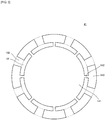
Fig. 8] Fig. 8 is a plan view of ahousing 517 according to a first modification of afirst housing 17 shown inFig. 1 . - [
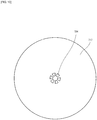
Fig. 9] Fig. 9 is a plan view of ahousing 617 according to a second modification of thefirst housing 17 shown inFig. 1 . - [
Fig. 10] Fig. 10 is a plan view of ahousing 717 according to a third modification of thefirst housing 17 shown inFig. 1 . - [
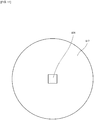
Fig. 11] Fig. 11 is a plan view of ahousing 817 according to a fourth modification of thefirst housing 17 shown inFig. 1 . - The
piezoelectric blower 100 according to an embodiment of the present invention is described below. -
Fig. 1 is an external perspective view of thepiezoelectric blower 100 according to the embodiment of the present invention.Fig. 2 is an external perspective view of thepiezoelectric blower 100 shown inFig. 1 .Fig. 3 is a plan view of the vibratingplate 41 shown inFig. 1 .Fig. 4 is a sectional view taken along line S-S of thepiezoelectric blower 100 shown inFig. 1 . - The
piezoelectric blower 100 includes afirst valve 80, thefirst housing 17, the vibratingplate 41, apiezoelectric element 42, asecond housing 117, and asecond valve 180 in that order from the top, and has a structure in which these components are successively placed upon each other. - The vibrating
plate 41 is disc-shaped, and is made of, for example, stainless steel (SUS). The thickness of the vibratingplate 41 is 0.6 mm. The vibratingplate 41 includes a firstprincipal surface 40A and a secondprincipal surface 40B. - As shown in
Fig. 3 , the vibratingplate 41 includes a vibratingportion 141, a thirdside wall portion 143, and a connectingportion 142. Thepiezoelectric element 42 is provided on the vibratingportion 141, and causes the vibratingportion 141 to undergo bending vibration. The thirdside wall portion 143 surrounds the vibratingportion 141 and is joined to a firstside wall portion 19 and a second side wall portion 119 (described below). The connectingportion 142 connects the vibratingportion 141 and the thirdside wall portion 143, and elastically supports the vibratingportion 141 with respect to the thirdside wall portion 143. The vibratingplate 41 is formed by, for example, punching a metallic plate. - The
piezoelectric element 42 is disc-shaped, and is made of, for example, a lead zirconate titanate ceramic. Electrodes are formed on two principal surfaces of thepiezoelectric element 42. Thepiezoelectric element 42 is joined to the secondprincipal surface 40B of the vibratingplate 41 at a side of asecond blower chamber 131, and expands and contracts in accordance with an applied alternating voltage. Here, the vibratingportion 141, the connectingportion 142, and thepiezoelectric element 42 form anactuator 50. - The
first housing 17 has a C-shaped cross section having an open bottom. The ends of thefirst housing 17 are joined to the firstprincipal surface 40A of the vibratingplate 41. Thefirst housing 17 is made of, for example, a metal. - The
first housing 17 forms, together with the vibratingplate 41, the column-shapedfirst blower chamber 31 such that thefirst blower chamber 31 is interposed therebetween in a thickness direction of the vibratingplate 41. The vibratingplate 41 and thefirst housing 17 are formed such that thefirst blower chamber 31 has a radius a. In the embodiment, the radius a of thefirst blower chamber 31 is 6.1 mm. - The
first blower chamber 31 refers to a space that exists inwardly from opening portions 62 (more precisely, a space that exists inwardly from a ring formed by connecting all of the opening portions 62) when the firstprincipal surface 40A of the vibratingplate 41 is viewed from the front. Therefore, a region that exists inwardly from the openingportions 62 at the firstprincipal surface 40A of the vibrating plate 41 (more precisely, a region that exists inwardly from the ring that is formed by connecting all of the opening portions 62) forms a bottom surface of thefirst blower chamber 31. - The
first housing 17 includes a disc-shaped firsttop plate portion 18 opposing the firstprincipal surface 40A of the vibratingplate 41 and the disc-shaped firstside wall portion 19 that is connected to the firsttop plate portion 18. A portion of the firsttop plate portion 18 forms a top surface of thefirst blower chamber 31. - The first
top plate portion 18 includes a column-shapedfirst vent hole 24 that allows a central portion of thefirst blower chamber 31 to communicate with the outside of thefirst blower chamber 31. The central portion of thefirst blower chamber 31 is a portion that overlaps thepiezoelectric element 42 when the secondprincipal surface 40B of the vibratingplate 41 is viewed from the front. In the present embodiment, the diameter of thefirst vent hole 24 is 0.6 mm. The firsttop plate portion 18 is provided with thefirst valve 80 that prevents gas from flowing into thefirst blower chamber 31 from the outside of thefirst blower chamber 31 through thefirst vent hole 24. - The
second housing 117 has a C-shaped cross section having an open top. The ends of thesecond housing 117 are joined to the secondprincipal surface 40B of the vibratingplate 41. Thesecond housing 117 is made of, for example, a metal. - The
second housing 117 forms, together with theactuator 50, the column-shapedsecond blower chamber 131 such that thesecond blower chamber 131 is interposed therebetween in the thickness direction of the vibratingplate 41. The vibratingplate 41 and thesecond housing 117 are formed such that thesecond blower chamber 131 has a radius a. In the embodiment, the radius a of thesecond blower chamber 131 is also 6.1 mm. - The
second blower chamber 131 refers to a space that exists inwardly from the opening portions 62 (more precisely, a space that exists inwardly from the ring formed by connecting all of the opening portions 62) when the secondprincipal surface 40B of the vibratingplate 41 is viewed from the front. Therefore, a region that exists inwardly from the openingportions 62 at a second-vent-hole-124-side surface of the actuator 50 (more precisely, a region that exists inwardly from the ring that is formed by connecting all of the opening portions 62) forms a bottom surface of thesecond blower chamber 131. - The
second housing 117 includes a disc-shaped secondtop plate portion 118 opposing the secondprincipal surface 40B of the vibratingplate 41 and the disc-shaped secondside wall portion 119 that is connected to the secondtop plate portion 118. A portion of the secondtop plate portion 118 forms a top surface of thesecond blower chamber 131. - The second
top plate portion 118 includes a column-shapedsecond vent hole 124 that allows a central portion of thesecond blower chamber 131 to communicate with the outside of thesecond blower chamber 131. The central portion of thesecond blower chamber 131 is a portion that overlaps thepiezoelectric element 42 when the secondprincipal surface 40B of the vibratingplate 41 is viewed from the front. In the present embodiment, the diameter of thesecond vent hole 124 is 0.6 mm. The secondtop plate portion 118 is provided with thesecond valve 180 that prevents gas from flowing into thesecond blower chamber 131 from the outside of thesecond blower chamber 131 through thesecond vent hole 124. - Here, as shown in
Figs. 1 and2 , thefirst housing 17, the thirdside wall portion 143, and thesecond housing 117 form ahousing 90. Therefore, a joined body, where the firstside wall portion 19, the thirdside wall portion 143, and the secondside wall portion 119 are joined together, connects the vibratingportion 141 and the connectingportion 142 to the firsttop plate portion 18 and the vibratingportion 141 and the connectingportion 142 to the secondtop plate portion 118. - As shown in
Figs. 3 and4 , the vibratingplate 41 includes the openingportions 62 that allow an outer periphery of thefirst blower chamber 31 and an outer periphery of thesecond blower chamber 131 to communicate with each other. The openingportions 62 are formed along substantially the entire periphery of the vibratingplate 41 so as to surround thefirst blower chamber 31 and thesecond blower chamber 131. - As shown in
Figs. 3 and4 , the vibratingplate 41 includes a plurality of third vent holes 162. That is, the plurality of third vent holes 162 are provided in the thirdside wall portion 143. The third vent holes 162 allow the openingportions 62 and the outside of thehousing 90 to communicate with each other. Therefore, the third vent holes 162 allow the outer periphery of thefirst blower chamber 31 and the outer periphery of thesecond blower chamber 131 to communicate with the outside of thehousing 90 through the openingportions 62. - In this embodiment, the
piezoelectric element 42 corresponds to a "driving member" according to the present invention. The vibratingportion 141 and the connectingportion 142 correspond to a "vibrating portion" according to the present invention. The firstside wall portion 19, the thirdside wall portion 143, and the secondside wall portion 119 correspond to a "side wall portion" according to the present invention. - The flow of air when the
piezoelectric blower 100 operates is described below. -
Figs. 5(A) and 5(B) are sectional views taken along line S-S of thepiezoelectric blower 100 shown inFig. 1 when thepiezoelectric blower 100 operates at a first-order mode resonant frequency (fundamental).Fig. 5(A) illustrates a case in which the volume of thefirst blower chamber 31 has been maximally increased and in which the volume of thesecond blower chamber 131 has been maximally reduced, andFig. 5(B) illustrates a case in which the volume of thefirst blower chamber 31 has been maximally reduced and in which the volume of thesecond blower chamber 131 has been maximally increased. Here, the illustrated arrows denote the flow of air. -
Fig. 6 shows the relationship between pressure change at each point at thefirst blower chamber 31 from a central axis C of thefirst blower chamber 31 to the outer periphery of thefirst blower chamber 31 and displacement of each point on the vibratingplate 41 from the central axis C of thefirst blower chamber 31 to the outer periphery of thefirst blower chamber 31, at a moment when thepiezoelectric blower 100 shown inFig. 1 is set in the state shown inFig. 5(B) . - Here, in
Fig. 6 , the pressure change at each point at thefirst blower chamber 31 and the displacement of each point on the vibratingplate 41 are indicated by a value that has been standardized based on the displacement of the center of the vibratingplate 41 existing on the central axis C of thefirst blower chamber 31. - A pressure change distribution u(r) shown in
Fig. 6 is described later. Pressure change at each point at thesecond blower chamber 131 from a central axis C of thesecond blower chamber 131 to the outer periphery of thesecond blower chamber 131, at a moment when thepiezoelectric blower 100 shown inFig. 1 is set in the state shown inFig. 5(A) is substantially equal to the pressure change at each point at thefirst blower chamber 31. This is shown inFig. 6 . -
Fig. 7 shows the relationship between radius a × resonant frequency f and pressure amplitude in thefirst blower chamber 31 of thepiezoelectric blower 100 shown inFig. 1 . The dotted lines inFig. 7 indicate a lower limit and an upper limit of a range satisfying the relationship of 0.8 × (k0c)/(2π) ≤ af ≤ 1.2 × (k0c)/(2π). - The relationship between radius a × resonant frequency f and pressure amplitude in the
second blower chamber 131 is substantially the same as the relationship between radius a × resonant frequency f and pressure amplitude in thefirst blower chamber 31. This is shown inFig. 7 . - When, in the state shown in
Fig. 4 , an alternating drive voltage with the first-order mode frequency (fundamental) is applied to the electrodes on the two principal surfaces of thepiezoelectric element 42, thepiezoelectric element 42 expands and contracts and causes the vibratingplate 41 to undergo concentric bending vibration at the first-order mode resonant frequency f. - At the same time, due to pressure variations in the
first blower chamber 31 resulting from the bending vibration of the vibratingplate 41, the firsttop plate portion 18 undergoes concentric bending vibration in the first-order mode as the vibratingplate 41 undergoes the bending vibration (in this embodiment, such that the vibration phase lags by 180 degrees). - Due to pressure variations in the
second blower chamber 131 resulting from the bending vibration of the vibratingplate 41, the secondtop plate portion 118 also undergoes concentric bending vibration in the first-order mode as the vibratingplate 41 undergoes the bending vibration (in this embodiment, such that the vibration phase lags by 180 degrees). - By this, as shown in
Figs. 5(A) and 5(B) , the volume of thefirst blower chamber 31 and the volume of thesecond blower chamber 131 change periodically. - The radius a of the
first blower chamber 31 and the resonant frequency f of the vibratingplate 41 satisfy the relationship of 0.8 × (k0c)/(2π) ≤ af ≤ 1.2 × (k0c)/(2π). In addition, the radius a of thesecond blower chamber 131 and the resonant frequency f of the vibratingplate 41 also satisfy the relationship of 0.8 × (k0c)/(2π) ≤ af ≤ 1.2 × (k0c) / (2π). - In the embodiment, the resonant frequency f is 21 kHz. The acoustic velocity c of air is 340 m/s. k0 is 2.40. The Bessel function of the first kind J0(x) is expressed by the following numerical formula.

- The pressure change distribution u(r) of the points at the
first blower chamber 31 is expressed by the formula u(r) = J0(k0r/a), where the distance from the central axis C of thefirst blower chamber 31 is r. In addition, the pressure change distribution u(r) of the points at thesecond blower chamber 131 is also expressed by the formula u(r) = J0(k0r/a). - As shown in
Fig. 5(A) , when the vibratingplate 41 bends towards thepiezoelectric element 42, the firsttop plate portion 18 bends towards a side opposite to thepiezoelectric element 42, so that the volume of thefirst blower chamber 31 is increased. Further, the secondtop plate portion 118 bends towards thepiezoelectric element 42, so that the volume of thesecond blower chamber 131 is reduced. - At this time, since the pressure at the central portion of the
first blower chamber 31 is reduced, thefirst valve 80 is closed, and air that exists outside of thehousing 90 and air in thesecond blower chamber 131 are sucked into thefirst blower chamber 31 through the third vent holes 162 and the openingportions 62. At this time, since the pressure at the central portion of thesecond blower chamber 131 is increased, thesecond valve 180 opens, and air in the central portion of thesecond blower chamber 131 is discharged to the outside of thesecond housing 117 through thesecond vent hole 124. - As shown in
Fig. 5(B) , when the vibratingplate 41 bends towards thefirst blower chamber 31, the firsttop plate portion 18 bends towards thepiezoelectric element 42, so that the volume of thefirst blower chamber 31 is reduced. Further, the secondtop plate portion 118 bends towards the side opposite to thepiezoelectric element 42, so that the volume of thesecond blower chamber 131 is increased. - At this time, since the pressure at the central portion of the
first blower chamber 31 is increased, thefirst valve 80 opens, and air in the central portion of thefirst blower chamber 31 is discharged to the outside of thefirst housing 17 through thefirst vent hole 24. In addition, at this time, since the pressure at the central portion of thesecond blower chamber 131 is reduced, thesecond valve 180 is closed, and air that exists outside of thehousing 90 and air in thefirst blower chamber 31 are sucked into thesecond blower chamber 131 through the third vent holes 162 and the openingportions 62. - In the operation of the
piezoelectric blower 100 above, as shown inFigs. 5(A) and 5(B) , when the volume of thesecond blower chamber 131 is reduced, the volume of thefirst blower chamber 31 is increased, whereas, when the volume of thefirst blower chamber 31 is reduced, the volume of thesecond blower chamber 131 is increased. That is, the volume of thefirst blower chamber 31 and the volume of thesecond blower chamber 131 change in an opposite manner. - Therefore, when the
actuator 50 is driven, air at the outer periphery of thefirst blower chamber 31 and air at the outer periphery of thesecond blower chamber 131 move through the openingportions 62. Consequently, when theactuator 50 is driven, the pressure at the outer periphery of thefirst blower chamber 31 and the pressure at the outer periphery of thesecond blower chamber 131 cancel out through the openingportions 62, and are atmospheric pressure (node) at all times. - Therefore, even if the outer periphery of the
first blower chamber 31 and the outer periphery of thesecond blower chamber 131 communicate with the outside of thehousing 90 through thelarge opening portions 62 and the third vent holes 162, thepiezoelectric blower 100 can prevent a reduction in discharge pressure and discharge flow rate. - The
piezoelectric blower 100 is such that, when driving theactuator 50, air in thefirst blower chamber 31 sucked from the third vent holes 162 is discharged to the outside of thefirst housing 17 through thefirst vent hole 24, and air in thesecond blower chamber 131 sucked from the third vent holes 162 is discharged to the outside of thesecond housing 117 through thesecond vent hole 124. - Therefore, the
piezoelectric blower 100 having this structure can make the discharge flow rate per power consumption considerably higher than the discharge flow rate of the pump that is described inPatent Document 1 and that performs discharge from one vent hole (outlet). - The
piezoelectric blower 100 is capable of intercepting ultrasonic waves emitted from thepiezoelectric element 42 by using thesecond housing 117. - The plurality of third vent holes 162 are provided in the third
side wall portion 143. - Therefore, the shortest distance from the outer periphery of the
first blower chamber 31 to eachthird vent hole 162 and the shortest distance from the outer periphery of thesecond blower chamber 131 to eachthird vent hole 162 are substantially equal to each other. Consequently, when theactuator 50 is driven, the pressure at the outer periphery of thefirst blower chamber 31 and the pressure at the outer periphery of thesecond blower chamber 131 both tend to become stable at atmospheric pressure (node). - The
piezoelectric blower 100 includes thefirst valve 80 and thesecond valve 180. Therefore, as shown inFigs. 5(A) and 5(B) , air is not sucked into thefirst blower chamber 31 from the outside of thepiezoelectric blower 100 through thefirst vent hole 24 and air is not sucked into thesecond blower chamber 131 from the outside of thepiezoelectric blower 100 through thesecond vent hole 124. That is, thepiezoelectric blower 100 does not cause air current to flow in opposite directions through thefirst vent hole 24 and thesecond vent hole 124. Therefore, in thepiezoelectric blower 100, the air can flow in one direction. - In the
piezoelectric blower 100, since the firsttop plate portion 18 and the secondtop plate portion 118 vibrate as the vibratingplate 41 vibrates, it is possible to essentially increase vibration amplitude. Therefore, thepiezoelectric blower 100 according to the present embodiment can further increase discharge pressure and discharge flow rate. - When af = (k0c)/(2π), a node F of vibration of the vibrating
plate 41 coincides with a node of pressure vibration of thefirst blower chamber 31 and a node of pressure vibration of thesecond blower chamber 131, and pressure resonance occurs. - Further, even when the relationship of 0.8 × (k0c)/(2π) af ≤ 1.2 × (k0c)/(2π) is satisfied, the node F of vibration of the vibrating
plate 41 substantially coincides with the node of pressure vibration of thefirst blower chamber 31 and the node of pressure vibration of thesecond blower chamber 131. - The
piezoelectric blower 100 is used for sucking a liquid having high viscosity, such as nasal mucus or phlegm. In order to prevent breakage of the piezoelectric element resulting from driving the piezoelectric element for a long time, the vibration speed of the piezoelectric element needs to be less than or equal to 2 m/s. - In order to suck nasal mucus or phlegm, a pressure of 20 kPa or greater is required. Therefore, the
piezoelectric blower 100 requires a pressure amplitude of 10 kPa/(m/s) or greater. As shown inFig. 7 , the pressure amplitude becomes a maximum when af is 130 m/s. Even if the pressure amplitude deviates by ±20% from 130 m/s, a pressure amplitude of 10 kPa/(m/s) or greater can be obtained. - Therefore, when the relationship of 0.8 × (k0c)/(2π) ≤ af ≤ 1.2 × (k0c)/(2π) is satisfied, the
piezoelectric blower 100 can realize high discharge pressure and high discharge flow rate from both thefirst vent hole 24 and thesecond vent hole 124. - As shown in
Figs. 5(A) and 5(B) and the dotted line inFig. 6 , each point on the vibratingplate 41 from the central axis C of thefirst blower chamber 31 to the outer periphery of thefirst blower chamber 31 is displaced by vibration. As shown by the solid line inFig. 6 , from the central axis C of thefirst blower chamber 31 to the outer periphery of thefirst blower chamber 31, the pressure at each point at thefirst blower chamber 31 is changed due to the vibratingplate 41 being vibrated. Similarly, from the central axis C of thesecond blower chamber 131 to the outer periphery of thesecond blower chamber 131, the pressure at each point at thesecond blower chamber 131 is changed due to the vibratingplate 41 being vibrated. - As shown by the dotted line and the solid line in
Fig. 6 , in the range from the central axis C of thefirst blower chamber 31 to the outer periphery of thefirst blower chamber 31, the number of zero crossover points of the vibration displacement of the vibratingplate 41 is zero, the number of zero crossover points of the pressure change at thefirst blower chamber 31 is also zero, and the number of zero crossover points of the pressure change at thesecond blower chamber 131 is also zero. - Therefore, the number of zero crossover points of the vibration displacement of the vibrating
plate 41 is equal to the number of zero crossover points of the pressure change at thefirst blower chamber 31 and the number of zero crossover points of the pressure change at thesecond blower chamber 131. - Therefore, in the
piezoelectric blower 100, when the vibratingplate 41 vibrates, a distribution of the displacements of the respective points on the vibratingplate 41 becomes a distribution that is close to the distribution of the pressure changes at the respective points at thefirst blower chamber 31 and the distribution of the pressure changes at the respective points at thesecond blower chamber 131. - Therefore, the
piezoelectric blower 100 is capable of transmitting vibration energy of the vibratingplate 41 to air in thefirst blower chamber 31 and thesecond blower chamber 131 almost without loss of the vibration energy of the vibratingplate 41. Consequently, thepiezoelectric blower 100 can realize high discharge pressure and high discharge flow rate. - Although, in the above-described embodiment, air is used as the fluid, the present invention is not limited thereto. The fluid may be a gas other than air.
- Although, in the above-described embodiment, the vibrating
plate 41 is made of SUS, the present invention is not limited thereto. The vibratingplate 41 may be made of other materials, such as aluminum, titanium, magnesium, or copper. - Although, in the above-described embodiment, the
piezoelectric element 42 is provided as the driving source of the blower, the present invention is not limited thereto. For example, thepiezoelectric element 42 may be formed as a blower that performs pumping by electromagnetic driving. - Although, in the above-described embodiment, the
piezoelectric element 42 is made of a lead zirconate titanate ceramic, the present invention is not limited thereto. For example, thepiezoelectric element 42 may be made of piezoelectric materials of a non-lead piezoelectric ceramic such as a potassium sodium niobate based ceramic or an alkali niobate based ceramic. - Although, in the above-described embodiment, a unimorph piezoelectric vibrator is used, the present invention is not limited thereto. A bimorph piezoelectric vibrator in which the
piezoelectric element 42 is attached to each of two surfaces of the vibratingplate 41 may be used. - Although, in the above-described embodiment, the disc-shaped
piezoelectric element 42, the disc-shaped vibratingplate 41, and the disc-shaped firsttop plate portion 18, and the disc-shaped secondtop plate portion 118 are used, the present invention is not limited thereto. For example, they may have a rectangular or a polygonal shape. - Although, in the above-described embodiment, the vibrating
plate 41 undergoes concentric bending vibration, the present invention is not limited thereto. For implementation, the vibratingplate 41 may undergo bending vibration of a form other than concentric bending vibration. - Although, in the above-described embodiment, the first
top plate portion 18 and the secondtop plate portion 118 undergo concentric bending vibration as the vibratingplate 41 undergoes bending vibration, the present invention is not limited thereto. For implementation, only the vibratingplate 41 may undergo bending vibration, that is, the firsttop plate portion 18 and the secondtop plate portion 118 need not undergo bending vibration as the vibratingplate 41 undergoes bending vibration. - Although, in the above-described embodiment, k0 is 2.40 or 5.52, the present invention is not limited thereto. k0 may be any value that satisfies the relationship of J0(k0) = 0, such as 8.65, 11.79, or 14.93.
- Although, in the above-described embodiment, the
piezoelectric element 42 is joined to the secondprincipal surface 40B of the vibratingplate 41 at the side of thesecond blower chamber 131, the present invention is not limited thereto. For implementation, for example, thepiezoelectric element 42 may be joined to the firstprincipal surface 40A of the vibratingplate 41 at a side of thefirst blower chamber 31, or twopiezoelectric elements 42 may be joined to the first and secondprincipal surfaces plate 41. - In this case, the
first housing 17 and thesecond housing 117 form, together with an actuator including at least onepiezoelectric element 42 and the vibratingplate 41, a first blower chamber and a second blower chamber such that the first blower chamber is interposed between thefirst housing 17 and the actuator in the thickness direction of the vibratingplate 41 and such that the second blower chamber is interposed between thesecond housing 117 and the actuator in the thickness direction of the vibratingplate 41. - Although, in the above-described embodiment, the vibrating plate of the piezoelectric blower undergoes bending vibration at the first-order mode frequency or the third-order mode frequency, the present invention is not limited thereto. For implementation, the vibrating plate may undergo bending vibration in a vibration mode of a third-order mode or a higher odd-order mode producing a plurality of vibration antinodes.
- Although, in the above-described embodiment, the
first blower chamber 31 and thesecond blower chamber 131 are column-shaped, the present invention is not limited thereto. For implementation, the blower chambers may have the shape of a regular prism. In this case, instead of using the radius a of each blower chamber, the shortest distance a from the central axis of each blower chamber to the outer periphery of each blower chamber is used. - Although, in the above-described embodiment, the first
top plate portion 18 of thefirst housing 17 includes one circularfirst vent hole 24, and the secondtop plate portion 118 of thesecond housing 117 also includes one circularsecond vent hole 124, the present invention is not limited thereto. For implementation, for example, as shown inFigs. 8 to 10 , a plurality of vent holes 524 to a plurality of vent holes 724 may be provided; or, for example, as with the vent holes 624 and the vent holes 724 shown inFigs. 9 and10 and avent hole 824 shown inFig. 11 , the vent hole or vent holes need not be circular. - Although, in the above-described embodiment, the
first valve 80 is provided at thefirst vent hole 24, and thesecond valve 180 is provided at thesecond vent hole 124, the present invention is not limited thereto. For implementation, the valve need not be provided. - If the valve is not provided, when, as shown in
Figs. 5(A) , the vibratingplate 41 bends towards thepiezoelectric element 42, air current in a direction opposite to that inFigs. 5(B) is generated. Therefore, discharge flow and suction flow at a high wind speed are alternately generated from thefirst vent hole 24 and thesecond vent hole 124. That is, a strong reciprocating current can be produced. Such a strong reciprocating current can be used for, for example, cooling heat-generating parts. - Although, in the above-described embodiment, the third vent holes 162 are provided in the third
side wall portion 143, the present invention is not limited thereto. For implementation, the third vent holes 162 may be formed in the firstside wall portion 19 or the secondside wall portion 119. - Lastly, the description of the above-described embodiment is to be considered in all respects only as illustrative and not restrictive. The scope of the present invention is indicated by the claims rather than by the above-described embodiment. Further, all changes which come within the meaning and range of equivalency of the claims are to be embraced within the scope of the present invention. Reference Signs List
-
- a
- radius
- C
- central axis
- F
- node
- 17
- first housing
- 18
- first top plate portion
- 19
- first side wall portion
- 24
- first vent hole
- 31
- first blower chamber
- 40A
- first principal surface
- 40B
- second principal surface
- 41
- vibrating plate
- 42
- piezoelectric element
- 50
- actuator
- 62
- opening portion
- 80
- first valve
- 90
- housing
- 100
- piezoelectric blower
- 117
- second housing
- 118
- second top plate portion
- 119
- second side wall portion
- 124
- second vent hole
- 131
- second blower chamber
- 141
- vibrating portion
- 142
- connecting portion
- 143
- third side wall portion
- 162
- third vent hole
- 180
- second valve
- 517
- housing
- 524
- vent hole
- 617
- housing
- 624
- vent hole
- 717
- housing
- 724
- vent hole
- 817
- housing
- 824
- vent hole
Claims (9)
- A blower comprising:an actuator including a vibrating portion and a driving member, the vibrating portion including a first principal surface and a second principal surface, the driving member being provided on at least one of the first principal surface and the second principal surface of the vibrating portion, the driving member causing the vibrating portion to undergo bending vibration; anda housing including a first top plate portion, a second top plate portion, and a side wall portion, the first top plate portion forming, together with the actuator, a first blower chamber and including a first vent hole, the second top plate portion forming, together with the actuator, a second blower chamber and including a second vent hole, the side wall portion connecting the first top plate portion and the vibrating portion and connecting the second top plate portion and the vibrating portion,wherein the vibrating portion includes an opening portion that allows an outer periphery of the first blower chamber and an outer periphery of the second blower chamber to communicate with each other, andwherein the side wall portion includes a third vent hole that allows the outer periphery of the first blower chamber and the outer periphery of the second blower chamber to communicate with an outside of the housing.
- The blower according to Claim 1, wherein the third vent hole is provided in a region of the side wall portion that surrounds the vibrating portion, and allows the opening portion and the outside of the housing to communicate with each other.
- The blower according to either Claim 1 or Claim 2, wherein a first valve that prevents a gas from flowing into the first blower chamber from an outside of the first blower chamber is provided at the first vent hole.
- The blower according to any one of Claims 1 to 3, wherein a second valve that prevents the gas from flowing into the second blower chamber from an outside of the second blower chamber is provided at the second vent hole.
- The blower according to any one of Claims 1 to 4, wherein the driving member is a piezoelectric member.
- The blower according to any one of Claims 1 to 5, wherein the first top plate portion undergoes bending vibration as the vibrating plate undergoes bending vibration.
- The blower according to any one of Claims 1 to 6, wherein the second top plate portion undergoes bending vibration as the vibrating plate undergoes bending vibration.
- The blower according to any one of Claims 1 to 7, wherein a shortest distance a from a central axis of the first blower chamber to the outer periphery of the first blower chamber and a resonant frequency f of the vibrating plate satisfy a relationship of 0.8 × (k0c)/(2π) ≤ af ≤ 1.2 × (k0c)/(2π), where an acoustic velocity of gas that passes through the first blower chamber is c and a value that satisfies a relationship of a Bessel function of a first kind of J0(k0) - 0 is k0.
- The blower according to Claim 8, wherein a shortest distance from a central axis of the second blower chamber to the outer periphery of the second blower chamber is equal to the shortest distance a.
Applications Claiming Priority (2)
| Application Number | Priority Date | Filing Date | Title |
|---|---|---|---|
| JP2014104226 | 2014-05-20 | ||
| PCT/JP2015/060439 WO2015178104A1 (en) | 2014-05-20 | 2015-04-02 | Blower |
Publications (3)
| Publication Number | Publication Date |
|---|---|
| EP3147504A1 true EP3147504A1 (en) | 2017-03-29 |
| EP3147504A4 EP3147504A4 (en) | 2018-01-03 |
| EP3147504B1 EP3147504B1 (en) | 2021-11-03 |
Family
ID=54553780
Family Applications (1)
| Application Number | Title | Priority Date | Filing Date |
|---|---|---|---|
| EP15795463.7A Active EP3147504B1 (en) | 2014-05-20 | 2015-04-02 | Blower |
Country Status (5)
| Country | Link |
|---|---|
| US (1) | US10738773B2 (en) |
| EP (1) | EP3147504B1 (en) |
| JP (1) | JP6065160B2 (en) |
| CN (1) | CN106460828B (en) |
| WO (1) | WO2015178104A1 (en) |
Cited By (2)
| Publication number | Priority date | Publication date | Assignee | Title |
|---|---|---|---|---|
| WO2022023703A1 (en) * | 2020-07-31 | 2022-02-03 | Ttp Ventus Ltd. | Actuator for a resonant acoustic pump |
| EP4030055A4 (en) * | 2019-09-11 | 2023-10-04 | Kyocera Corporation | PIEZOELECTRIC PUMP AND PUMP UNIT |
Families Citing this family (12)
| Publication number | Priority date | Publication date | Assignee | Title |
|---|---|---|---|---|
| WO2015125608A1 (en) | 2014-02-21 | 2015-08-27 | 株式会社村田製作所 | Blower |
| CN105508207B (en) * | 2016-01-20 | 2019-01-22 | 吉林大学 | A cymbal type pump body piezoelectric pump |
| TWI625468B (en) | 2016-09-05 | 2018-06-01 | 研能科技股份有限公司 | Fluid control device |
| TWI602995B (en) * | 2016-09-05 | 2017-10-21 | 研能科技股份有限公司 | Fluid control device |
| TWI613367B (en) | 2016-09-05 | 2018-02-01 | 研能科技股份有限公司 | Fluid control device |
| TWI638097B (en) * | 2017-02-20 | 2018-10-11 | 研能科技股份有限公司 | Micro fluid transmission device |
| WO2019124060A1 (en) * | 2017-12-22 | 2019-06-27 | 株式会社村田製作所 | Pump |
| WO2019230189A1 (en) * | 2018-05-29 | 2019-12-05 | 株式会社村田製作所 | Fluid control device |
| CN112166251B (en) * | 2018-05-31 | 2024-04-02 | 株式会社村田制作所 | Fluid control device |
| TWI785908B (en) * | 2021-11-29 | 2022-12-01 | 研能科技股份有限公司 | Gas transportation device |
| US20240340576A1 (en) * | 2023-04-07 | 2024-10-10 | Sonicedge Ltd. | Ultrasonic Pump And Applications |
| CN222910217U (en) * | 2024-07-15 | 2025-05-27 | 江苏蚂蚁动力科技有限公司 | Gas conveying device |
Family Cites Families (12)
| Publication number | Priority date | Publication date | Assignee | Title |
|---|---|---|---|---|
| JPS60195987A (en) | 1984-03-19 | 1985-10-04 | 日立入間電子株式会社 | Electronic device |
| JPS60195987U (en) * | 1984-06-08 | 1985-12-27 | 株式会社三鈴エリー | piezoelectric vibrator pump |
| JPH01167475A (en) * | 1987-12-23 | 1989-07-03 | Hitachi Ltd | Pump employing piezoelectric element |
| GB0508194D0 (en) | 2005-04-22 | 2005-06-01 | The Technology Partnership Plc | Pump |
| CA2654688C (en) * | 2006-12-09 | 2011-07-26 | Murata Manufacturing Co., Ltd. | Piezoelectric pump |
| GB0804739D0 (en) * | 2008-03-14 | 2008-04-16 | The Technology Partnership Plc | Pump |
| US8371829B2 (en) * | 2010-02-03 | 2013-02-12 | Kci Licensing, Inc. | Fluid disc pump with square-wave driver |
| EP2557312B1 (en) * | 2010-05-21 | 2019-11-13 | Murata Manufacturing Co., Ltd. | Fluid pump |
| JP5682513B2 (en) * | 2011-09-06 | 2015-03-11 | 株式会社村田製作所 | Fluid control device |
| GB201202346D0 (en) * | 2012-02-10 | 2012-03-28 | The Technology Partnership Plc | Disc pump with advanced actuator |
| JP5928160B2 (en) | 2012-05-29 | 2016-06-01 | オムロンヘルスケア株式会社 | Piezoelectric pump and blood pressure information measuring apparatus including the same |
| JP5692468B2 (en) * | 2012-08-10 | 2015-04-01 | 株式会社村田製作所 | Blower |
-
2015
- 2015-04-02 WO PCT/JP2015/060439 patent/WO2015178104A1/en not_active Ceased
- 2015-04-02 CN CN201580026443.0A patent/CN106460828B/en active Active
- 2015-04-02 EP EP15795463.7A patent/EP3147504B1/en active Active
- 2015-04-02 JP JP2016520989A patent/JP6065160B2/en active Active
-
2016
- 2016-11-16 US US15/352,724 patent/US10738773B2/en active Active
Cited By (7)
| Publication number | Priority date | Publication date | Assignee | Title |
|---|---|---|---|---|
| EP4030055A4 (en) * | 2019-09-11 | 2023-10-04 | Kyocera Corporation | PIEZOELECTRIC PUMP AND PUMP UNIT |
| WO2022023703A1 (en) * | 2020-07-31 | 2022-02-03 | Ttp Ventus Ltd. | Actuator for a resonant acoustic pump |
| GB2611726A (en) * | 2020-07-31 | 2023-04-12 | Lee Ventus Ltd | Actuator for a resonant acoustic pump |
| GB2611726B (en) * | 2020-07-31 | 2024-12-04 | Lee Ventus Ltd | Actuator for a resonant acoustic pump |
| GB2632558A (en) * | 2020-07-31 | 2025-02-12 | Lee Ventus Ltd | Actuator for a resonant acoustic pump |
| GB2632558B (en) * | 2020-07-31 | 2025-05-28 | Lee Ventus Ltd | Actuator for a resonant acoustic pump |
| US12331759B2 (en) | 2020-07-31 | 2025-06-17 | Lee Ventus Ltd. | Method of making an actuator for a resonant acoustic pump |
Also Published As
| Publication number | Publication date |
|---|---|
| JP6065160B2 (en) | 2017-01-25 |
| EP3147504B1 (en) | 2021-11-03 |
| JPWO2015178104A1 (en) | 2017-04-20 |
| US10738773B2 (en) | 2020-08-11 |
| CN106460828B (en) | 2018-09-04 |
| WO2015178104A1 (en) | 2015-11-26 |
| CN106460828A (en) | 2017-02-22 |
| EP3147504A4 (en) | 2018-01-03 |
| US20170058884A1 (en) | 2017-03-02 |
Similar Documents
| Publication | Publication Date | Title |
|---|---|---|
| EP3147504B1 (en) | Blower | |
| US10233918B2 (en) | Blower | |
| US10221845B2 (en) | Blower | |
| JP6528849B2 (en) | Blower | |
| US10107281B2 (en) | Piezoelectric blower | |
| JP6572619B2 (en) | Blower | |
| US10260495B2 (en) | Blower with a vibrating body having a restraining plate located on a periphery of the body | |
| US10125760B2 (en) | Pump | |
| JPWO2016121717A1 (en) | Valve, fluid control device | |
| JP6380075B2 (en) | Blower |
Legal Events
| Date | Code | Title | Description |
|---|---|---|---|
| STAA | Information on the status of an ep patent application or granted ep patent |
Free format text: STATUS: THE INTERNATIONAL PUBLICATION HAS BEEN MADE |
|
| PUAI | Public reference made under article 153(3) epc to a published international application that has entered the european phase |
Free format text: ORIGINAL CODE: 0009012 |
|
| STAA | Information on the status of an ep patent application or granted ep patent |
Free format text: STATUS: REQUEST FOR EXAMINATION WAS MADE |
|
| 17P | Request for examination filed |
Effective date: 20161019 |
|
| AK | Designated contracting states |
Kind code of ref document: A1 Designated state(s): AL AT BE BG CH CY CZ DE DK EE ES FI FR GB GR HR HU IE IS IT LI LT LU LV MC MK MT NL NO PL PT RO RS SE SI SK SM TR |
|
| AX | Request for extension of the european patent |
Extension state: BA ME |
|
| DAV | Request for validation of the european patent (deleted) | ||
| DAX | Request for extension of the european patent (deleted) | ||
| A4 | Supplementary search report drawn up and despatched |
Effective date: 20171201 |
|
| RIC1 | Information provided on ipc code assigned before grant |
Ipc: F04B 43/00 20060101ALI20171127BHEP Ipc: F04B 43/02 20060101ALI20171127BHEP Ipc: F04B 39/12 20060101ALI20171127BHEP Ipc: F04B 45/04 20060101AFI20171127BHEP Ipc: F04B 53/16 20060101ALI20171127BHEP Ipc: F04B 53/10 20060101ALI20171127BHEP Ipc: F04B 43/04 20060101ALI20171127BHEP Ipc: F04B 45/047 20060101ALI20171127BHEP |
|
| STAA | Information on the status of an ep patent application or granted ep patent |
Free format text: STATUS: EXAMINATION IS IN PROGRESS |
|
| 17Q | First examination report despatched |
Effective date: 20180807 |
|
| GRAP | Despatch of communication of intention to grant a patent |
Free format text: ORIGINAL CODE: EPIDOSNIGR1 |
|
| STAA | Information on the status of an ep patent application or granted ep patent |
Free format text: STATUS: GRANT OF PATENT IS INTENDED |
|
| INTG | Intention to grant announced |
Effective date: 20210528 |
|
| GRAS | Grant fee paid |
Free format text: ORIGINAL CODE: EPIDOSNIGR3 |
|
| GRAA | (expected) grant |
Free format text: ORIGINAL CODE: 0009210 |
|
| STAA | Information on the status of an ep patent application or granted ep patent |
Free format text: STATUS: THE PATENT HAS BEEN GRANTED |
|
| AK | Designated contracting states |
Kind code of ref document: B1 Designated state(s): AL AT BE BG CH CY CZ DE DK EE ES FI FR GB GR HR HU IE IS IT LI LT LU LV MC MK MT NL NO PL PT RO RS SE SI SK SM TR |
|
| REG | Reference to a national code |
Ref country code: GB Ref legal event code: FG4D |
|
| REG | Reference to a national code |
Ref country code: AT Ref legal event code: REF Ref document number: 1444177 Country of ref document: AT Kind code of ref document: T Effective date: 20211115 Ref country code: CH Ref legal event code: EP |
|
| REG | Reference to a national code |
Ref country code: DE Ref legal event code: R096 Ref document number: 602015074717 Country of ref document: DE |
|
| REG | Reference to a national code |
Ref country code: IE Ref legal event code: FG4D |
|
| REG | Reference to a national code |
Ref country code: LT Ref legal event code: MG9D |
|
| REG | Reference to a national code |
Ref country code: NL Ref legal event code: MP Effective date: 20211103 |
|
| REG | Reference to a national code |
Ref country code: AT Ref legal event code: MK05 Ref document number: 1444177 Country of ref document: AT Kind code of ref document: T Effective date: 20211103 |
|
| PG25 | Lapsed in a contracting state [announced via postgrant information from national office to epo] |
Ref country code: RS Free format text: LAPSE BECAUSE OF FAILURE TO SUBMIT A TRANSLATION OF THE DESCRIPTION OR TO PAY THE FEE WITHIN THE PRESCRIBED TIME-LIMIT Effective date: 20211103 Ref country code: LT Free format text: LAPSE BECAUSE OF FAILURE TO SUBMIT A TRANSLATION OF THE DESCRIPTION OR TO PAY THE FEE WITHIN THE PRESCRIBED TIME-LIMIT Effective date: 20211103 Ref country code: FI Free format text: LAPSE BECAUSE OF FAILURE TO SUBMIT A TRANSLATION OF THE DESCRIPTION OR TO PAY THE FEE WITHIN THE PRESCRIBED TIME-LIMIT Effective date: 20211103 Ref country code: BG Free format text: LAPSE BECAUSE OF FAILURE TO SUBMIT A TRANSLATION OF THE DESCRIPTION OR TO PAY THE FEE WITHIN THE PRESCRIBED TIME-LIMIT Effective date: 20220203 Ref country code: AT Free format text: LAPSE BECAUSE OF FAILURE TO SUBMIT A TRANSLATION OF THE DESCRIPTION OR TO PAY THE FEE WITHIN THE PRESCRIBED TIME-LIMIT Effective date: 20211103 |
|
| PG25 | Lapsed in a contracting state [announced via postgrant information from national office to epo] |
Ref country code: IS Free format text: LAPSE BECAUSE OF FAILURE TO SUBMIT A TRANSLATION OF THE DESCRIPTION OR TO PAY THE FEE WITHIN THE PRESCRIBED TIME-LIMIT Effective date: 20220303 Ref country code: SE Free format text: LAPSE BECAUSE OF FAILURE TO SUBMIT A TRANSLATION OF THE DESCRIPTION OR TO PAY THE FEE WITHIN THE PRESCRIBED TIME-LIMIT Effective date: 20211103 Ref country code: PT Free format text: LAPSE BECAUSE OF FAILURE TO SUBMIT A TRANSLATION OF THE DESCRIPTION OR TO PAY THE FEE WITHIN THE PRESCRIBED TIME-LIMIT Effective date: 20220303 Ref country code: PL Free format text: LAPSE BECAUSE OF FAILURE TO SUBMIT A TRANSLATION OF THE DESCRIPTION OR TO PAY THE FEE WITHIN THE PRESCRIBED TIME-LIMIT Effective date: 20211103 Ref country code: NO Free format text: LAPSE BECAUSE OF FAILURE TO SUBMIT A TRANSLATION OF THE DESCRIPTION OR TO PAY THE FEE WITHIN THE PRESCRIBED TIME-LIMIT Effective date: 20220203 Ref country code: NL Free format text: LAPSE BECAUSE OF FAILURE TO SUBMIT A TRANSLATION OF THE DESCRIPTION OR TO PAY THE FEE WITHIN THE PRESCRIBED TIME-LIMIT Effective date: 20211103 Ref country code: LV Free format text: LAPSE BECAUSE OF FAILURE TO SUBMIT A TRANSLATION OF THE DESCRIPTION OR TO PAY THE FEE WITHIN THE PRESCRIBED TIME-LIMIT Effective date: 20211103 Ref country code: HR Free format text: LAPSE BECAUSE OF FAILURE TO SUBMIT A TRANSLATION OF THE DESCRIPTION OR TO PAY THE FEE WITHIN THE PRESCRIBED TIME-LIMIT Effective date: 20211103 Ref country code: GR Free format text: LAPSE BECAUSE OF FAILURE TO SUBMIT A TRANSLATION OF THE DESCRIPTION OR TO PAY THE FEE WITHIN THE PRESCRIBED TIME-LIMIT Effective date: 20220204 Ref country code: ES Free format text: LAPSE BECAUSE OF FAILURE TO SUBMIT A TRANSLATION OF THE DESCRIPTION OR TO PAY THE FEE WITHIN THE PRESCRIBED TIME-LIMIT Effective date: 20211103 |
|
| PG25 | Lapsed in a contracting state [announced via postgrant information from national office to epo] |
Ref country code: SM Free format text: LAPSE BECAUSE OF FAILURE TO SUBMIT A TRANSLATION OF THE DESCRIPTION OR TO PAY THE FEE WITHIN THE PRESCRIBED TIME-LIMIT Effective date: 20211103 Ref country code: SK Free format text: LAPSE BECAUSE OF FAILURE TO SUBMIT A TRANSLATION OF THE DESCRIPTION OR TO PAY THE FEE WITHIN THE PRESCRIBED TIME-LIMIT Effective date: 20211103 Ref country code: RO Free format text: LAPSE BECAUSE OF FAILURE TO SUBMIT A TRANSLATION OF THE DESCRIPTION OR TO PAY THE FEE WITHIN THE PRESCRIBED TIME-LIMIT Effective date: 20211103 Ref country code: EE Free format text: LAPSE BECAUSE OF FAILURE TO SUBMIT A TRANSLATION OF THE DESCRIPTION OR TO PAY THE FEE WITHIN THE PRESCRIBED TIME-LIMIT Effective date: 20211103 Ref country code: DK Free format text: LAPSE BECAUSE OF FAILURE TO SUBMIT A TRANSLATION OF THE DESCRIPTION OR TO PAY THE FEE WITHIN THE PRESCRIBED TIME-LIMIT Effective date: 20211103 Ref country code: CZ Free format text: LAPSE BECAUSE OF FAILURE TO SUBMIT A TRANSLATION OF THE DESCRIPTION OR TO PAY THE FEE WITHIN THE PRESCRIBED TIME-LIMIT Effective date: 20211103 |
|
| REG | Reference to a national code |
Ref country code: DE Ref legal event code: R097 Ref document number: 602015074717 Country of ref document: DE |
|
| PLBE | No opposition filed within time limit |
Free format text: ORIGINAL CODE: 0009261 |
|
| STAA | Information on the status of an ep patent application or granted ep patent |
Free format text: STATUS: NO OPPOSITION FILED WITHIN TIME LIMIT |
|
| 26N | No opposition filed |
Effective date: 20220804 |
|
| PG25 | Lapsed in a contracting state [announced via postgrant information from national office to epo] |
Ref country code: AL Free format text: LAPSE BECAUSE OF FAILURE TO SUBMIT A TRANSLATION OF THE DESCRIPTION OR TO PAY THE FEE WITHIN THE PRESCRIBED TIME-LIMIT Effective date: 20211103 |
|
| REG | Reference to a national code |
Ref country code: DE Ref legal event code: R119 Ref document number: 602015074717 Country of ref document: DE |
|
| PG25 | Lapsed in a contracting state [announced via postgrant information from national office to epo] |
Ref country code: SI Free format text: LAPSE BECAUSE OF FAILURE TO SUBMIT A TRANSLATION OF THE DESCRIPTION OR TO PAY THE FEE WITHIN THE PRESCRIBED TIME-LIMIT Effective date: 20211103 |
|
| REG | Reference to a national code |
Ref country code: CH Ref legal event code: PL |
|
| REG | Reference to a national code |
Ref country code: BE Ref legal event code: MM Effective date: 20220430 |
|
| PG25 | Lapsed in a contracting state [announced via postgrant information from national office to epo] |
Ref country code: MC Free format text: LAPSE BECAUSE OF FAILURE TO SUBMIT A TRANSLATION OF THE DESCRIPTION OR TO PAY THE FEE WITHIN THE PRESCRIBED TIME-LIMIT Effective date: 20211103 Ref country code: LU Free format text: LAPSE BECAUSE OF NON-PAYMENT OF DUE FEES Effective date: 20220402 Ref country code: LI Free format text: LAPSE BECAUSE OF NON-PAYMENT OF DUE FEES Effective date: 20220430 Ref country code: FR Free format text: LAPSE BECAUSE OF NON-PAYMENT OF DUE FEES Effective date: 20220430 Ref country code: DE Free format text: LAPSE BECAUSE OF NON-PAYMENT OF DUE FEES Effective date: 20221103 Ref country code: CH Free format text: LAPSE BECAUSE OF NON-PAYMENT OF DUE FEES Effective date: 20220430 |
|
| PG25 | Lapsed in a contracting state [announced via postgrant information from national office to epo] |
Ref country code: BE Free format text: LAPSE BECAUSE OF NON-PAYMENT OF DUE FEES Effective date: 20220430 |
|
| PG25 | Lapsed in a contracting state [announced via postgrant information from national office to epo] |
Ref country code: IE Free format text: LAPSE BECAUSE OF NON-PAYMENT OF DUE FEES Effective date: 20220402 |
|
| PG25 | Lapsed in a contracting state [announced via postgrant information from national office to epo] |
Ref country code: IT Free format text: LAPSE BECAUSE OF FAILURE TO SUBMIT A TRANSLATION OF THE DESCRIPTION OR TO PAY THE FEE WITHIN THE PRESCRIBED TIME-LIMIT Effective date: 20211103 |
|
| PG25 | Lapsed in a contracting state [announced via postgrant information from national office to epo] |
Ref country code: HU Free format text: LAPSE BECAUSE OF FAILURE TO SUBMIT A TRANSLATION OF THE DESCRIPTION OR TO PAY THE FEE WITHIN THE PRESCRIBED TIME-LIMIT; INVALID AB INITIO Effective date: 20150402 |
|
| PG25 | Lapsed in a contracting state [announced via postgrant information from national office to epo] |
Ref country code: MK Free format text: LAPSE BECAUSE OF FAILURE TO SUBMIT A TRANSLATION OF THE DESCRIPTION OR TO PAY THE FEE WITHIN THE PRESCRIBED TIME-LIMIT Effective date: 20211103 Ref country code: CY Free format text: LAPSE BECAUSE OF FAILURE TO SUBMIT A TRANSLATION OF THE DESCRIPTION OR TO PAY THE FEE WITHIN THE PRESCRIBED TIME-LIMIT Effective date: 20211103 |
|
| PG25 | Lapsed in a contracting state [announced via postgrant information from national office to epo] |
Ref country code: MT Free format text: LAPSE BECAUSE OF FAILURE TO SUBMIT A TRANSLATION OF THE DESCRIPTION OR TO PAY THE FEE WITHIN THE PRESCRIBED TIME-LIMIT Effective date: 20211103 |
|
| PGFP | Annual fee paid to national office [announced via postgrant information from national office to epo] |
Ref country code: GB Payment date: 20250423 Year of fee payment: 11 |
|
| PG25 | Lapsed in a contracting state [announced via postgrant information from national office to epo] |
Ref country code: TR Free format text: LAPSE BECAUSE OF FAILURE TO SUBMIT A TRANSLATION OF THE DESCRIPTION OR TO PAY THE FEE WITHIN THE PRESCRIBED TIME-LIMIT Effective date: 20211103 |