EP3147491A1 - Method for controlling an internal combustion engine of a motor vehicle - Google Patents
Method for controlling an internal combustion engine of a motor vehicle Download PDFInfo
- Publication number
- EP3147491A1 EP3147491A1 EP16190214.3A EP16190214A EP3147491A1 EP 3147491 A1 EP3147491 A1 EP 3147491A1 EP 16190214 A EP16190214 A EP 16190214A EP 3147491 A1 EP3147491 A1 EP 3147491A1
- Authority
- EP
- European Patent Office
- Prior art keywords
- fraction
- fresh air
- determined
- fresh
- gas
- Prior art date
- Legal status (The legal status is an assumption and is not a legal conclusion. Google has not performed a legal analysis and makes no representation as to the accuracy of the status listed.)
- Withdrawn
Links
Images

Classifications
-
- F—MECHANICAL ENGINEERING; LIGHTING; HEATING; WEAPONS; BLASTING
- F02—COMBUSTION ENGINES; HOT-GAS OR COMBUSTION-PRODUCT ENGINE PLANTS
- F02D—CONTROLLING COMBUSTION ENGINES
- F02D41/00—Electrical control of supply of combustible mixture or its constituents
- F02D41/0025—Controlling engines characterised by use of non-liquid fuels, pluralities of fuels, or non-fuel substances added to the combustible mixtures
- F02D41/0047—Controlling exhaust gas recirculation [EGR]
- F02D41/0065—Specific aspects of external EGR control
- F02D41/0072—Estimating, calculating or determining the EGR rate, amount or flow
-
- F—MECHANICAL ENGINEERING; LIGHTING; HEATING; WEAPONS; BLASTING
- F02—COMBUSTION ENGINES; HOT-GAS OR COMBUSTION-PRODUCT ENGINE PLANTS
- F02D—CONTROLLING COMBUSTION ENGINES
- F02D41/00—Electrical control of supply of combustible mixture or its constituents
- F02D41/0025—Controlling engines characterised by use of non-liquid fuels, pluralities of fuels, or non-fuel substances added to the combustible mixtures
- F02D41/0047—Controlling exhaust gas recirculation [EGR]
- F02D41/005—Controlling exhaust gas recirculation [EGR] according to engine operating conditions
- F02D41/0052—Feedback control of engine parameters, e.g. for control of air/fuel ratio or intake air amount
-
- F—MECHANICAL ENGINEERING; LIGHTING; HEATING; WEAPONS; BLASTING
- F02—COMBUSTION ENGINES; HOT-GAS OR COMBUSTION-PRODUCT ENGINE PLANTS
- F02D—CONTROLLING COMBUSTION ENGINES
- F02D41/00—Electrical control of supply of combustible mixture or its constituents
- F02D41/02—Circuit arrangements for generating control signals
- F02D41/14—Introducing closed-loop corrections
- F02D41/1438—Introducing closed-loop corrections using means for determining characteristics of the combustion gases; Sensors therefor
- F02D41/1439—Introducing closed-loop corrections using means for determining characteristics of the combustion gases; Sensors therefor characterised by the position of the sensor
- F02D41/144—Sensor in intake manifold
-
- F—MECHANICAL ENGINEERING; LIGHTING; HEATING; WEAPONS; BLASTING
- F02—COMBUSTION ENGINES; HOT-GAS OR COMBUSTION-PRODUCT ENGINE PLANTS
- F02D—CONTROLLING COMBUSTION ENGINES
- F02D41/00—Electrical control of supply of combustible mixture or its constituents
- F02D41/02—Circuit arrangements for generating control signals
- F02D41/14—Introducing closed-loop corrections
- F02D41/1438—Introducing closed-loop corrections using means for determining characteristics of the combustion gases; Sensors therefor
- F02D41/1444—Introducing closed-loop corrections using means for determining characteristics of the combustion gases; Sensors therefor characterised by the characteristics of the combustion gases
- F02D41/1454—Introducing closed-loop corrections using means for determining characteristics of the combustion gases; Sensors therefor characterised by the characteristics of the combustion gases the characteristics being an oxygen content or concentration or the air-fuel ratio
- F02D41/1458—Introducing closed-loop corrections using means for determining characteristics of the combustion gases; Sensors therefor characterised by the characteristics of the combustion gases the characteristics being an oxygen content or concentration or the air-fuel ratio with determination means using an estimation
-
- F—MECHANICAL ENGINEERING; LIGHTING; HEATING; WEAPONS; BLASTING
- F02—COMBUSTION ENGINES; HOT-GAS OR COMBUSTION-PRODUCT ENGINE PLANTS
- F02D—CONTROLLING COMBUSTION ENGINES
- F02D21/00—Controlling engines characterised by their being supplied with non-airborne oxygen or other non-fuel gas
- F02D21/06—Controlling engines characterised by their being supplied with non-airborne oxygen or other non-fuel gas peculiar to engines having other non-fuel gas added to combustion air
- F02D21/08—Controlling engines characterised by their being supplied with non-airborne oxygen or other non-fuel gas peculiar to engines having other non-fuel gas added to combustion air the other gas being the exhaust gas of engine
- F02D2021/083—Controlling engines characterised by their being supplied with non-airborne oxygen or other non-fuel gas peculiar to engines having other non-fuel gas added to combustion air the other gas being the exhaust gas of engine controlling exhaust gas recirculation electronically
-
- F—MECHANICAL ENGINEERING; LIGHTING; HEATING; WEAPONS; BLASTING
- F02—COMBUSTION ENGINES; HOT-GAS OR COMBUSTION-PRODUCT ENGINE PLANTS
- F02D—CONTROLLING COMBUSTION ENGINES
- F02D2200/00—Input parameters for engine control
- F02D2200/02—Input parameters for engine control the parameters being related to the engine
- F02D2200/04—Engine intake system parameters
- F02D2200/0402—Engine intake system parameters the parameter being determined by using a model of the engine intake or its components
-
- F—MECHANICAL ENGINEERING; LIGHTING; HEATING; WEAPONS; BLASTING
- F02—COMBUSTION ENGINES; HOT-GAS OR COMBUSTION-PRODUCT ENGINE PLANTS
- F02D—CONTROLLING COMBUSTION ENGINES
- F02D2200/00—Input parameters for engine control
- F02D2200/02—Input parameters for engine control the parameters being related to the engine
- F02D2200/04—Engine intake system parameters
- F02D2200/0406—Intake manifold pressure
-
- F—MECHANICAL ENGINEERING; LIGHTING; HEATING; WEAPONS; BLASTING
- F02—COMBUSTION ENGINES; HOT-GAS OR COMBUSTION-PRODUCT ENGINE PLANTS
- F02D—CONTROLLING COMBUSTION ENGINES
- F02D2200/00—Input parameters for engine control
- F02D2200/02—Input parameters for engine control the parameters being related to the engine
- F02D2200/04—Engine intake system parameters
- F02D2200/0414—Air temperature
-
- F—MECHANICAL ENGINEERING; LIGHTING; HEATING; WEAPONS; BLASTING
- F02—COMBUSTION ENGINES; HOT-GAS OR COMBUSTION-PRODUCT ENGINE PLANTS
- F02D—CONTROLLING COMBUSTION ENGINES
- F02D41/00—Electrical control of supply of combustible mixture or its constituents
- F02D41/02—Circuit arrangements for generating control signals
- F02D41/021—Introducing corrections for particular conditions exterior to the engine
- F02D41/0215—Introducing corrections for particular conditions exterior to the engine in relation with elements of the transmission
- F02D41/023—Introducing corrections for particular conditions exterior to the engine in relation with elements of the transmission in relation with the gear ratio shifting
-
- F—MECHANICAL ENGINEERING; LIGHTING; HEATING; WEAPONS; BLASTING
- F02—COMBUSTION ENGINES; HOT-GAS OR COMBUSTION-PRODUCT ENGINE PLANTS
- F02D—CONTROLLING COMBUSTION ENGINES
- F02D41/00—Electrical control of supply of combustible mixture or its constituents
- F02D41/02—Circuit arrangements for generating control signals
- F02D41/04—Introducing corrections for particular operating conditions
- F02D41/06—Introducing corrections for particular operating conditions for engine starting or warming up
- F02D41/062—Introducing corrections for particular operating conditions for engine starting or warming up for starting
-
- F—MECHANICAL ENGINEERING; LIGHTING; HEATING; WEAPONS; BLASTING
- F02—COMBUSTION ENGINES; HOT-GAS OR COMBUSTION-PRODUCT ENGINE PLANTS
- F02D—CONTROLLING COMBUSTION ENGINES
- F02D41/00—Electrical control of supply of combustible mixture or its constituents
- F02D41/02—Circuit arrangements for generating control signals
- F02D41/14—Introducing closed-loop corrections
- F02D41/1438—Introducing closed-loop corrections using means for determining characteristics of the combustion gases; Sensors therefor
- F02D41/1444—Introducing closed-loop corrections using means for determining characteristics of the combustion gases; Sensors therefor characterised by the characteristics of the combustion gases
- F02D41/1454—Introducing closed-loop corrections using means for determining characteristics of the combustion gases; Sensors therefor characterised by the characteristics of the combustion gases the characteristics being an oxygen content or concentration or the air-fuel ratio
-
- F—MECHANICAL ENGINEERING; LIGHTING; HEATING; WEAPONS; BLASTING
- F02—COMBUSTION ENGINES; HOT-GAS OR COMBUSTION-PRODUCT ENGINE PLANTS
- F02D—CONTROLLING COMBUSTION ENGINES
- F02D41/00—Electrical control of supply of combustible mixture or its constituents
- F02D41/02—Circuit arrangements for generating control signals
- F02D41/18—Circuit arrangements for generating control signals by measuring intake air flow
-
- Y—GENERAL TAGGING OF NEW TECHNOLOGICAL DEVELOPMENTS; GENERAL TAGGING OF CROSS-SECTIONAL TECHNOLOGIES SPANNING OVER SEVERAL SECTIONS OF THE IPC; TECHNICAL SUBJECTS COVERED BY FORMER USPC CROSS-REFERENCE ART COLLECTIONS [XRACs] AND DIGESTS
- Y02—TECHNOLOGIES OR APPLICATIONS FOR MITIGATION OR ADAPTATION AGAINST CLIMATE CHANGE
- Y02T—CLIMATE CHANGE MITIGATION TECHNOLOGIES RELATED TO TRANSPORTATION
- Y02T10/00—Road transport of goods or passengers
- Y02T10/10—Internal combustion engine [ICE] based vehicles
- Y02T10/40—Engine management systems
Definitions
- the invention relates to the technical field control of internal combustion engines, including such control during transient operating phases.
- the air supply chain is poorly controlled.
- the fuel injection is cut in order to cancel the torque perceived by the clutch during its opening and closing.
- the flow of the EGR circuit (high and low pressure) is also cut or minimized so as not to defuse the gaseous vein, that is to say the duct in which the EGR exhaust gas circulates, in order to avoid an excess of EGR in the cylinders during the restart phase.
- the risk of not being able to restart combustion due to lack of oxygen is avoided.
- the injection is done without or with little EGR, resulting in high levels of production of NOx nitrogen oxides.
- the subject of the invention is a method for controlling a motor vehicle internal combustion engine provided with a high-pressure partial exhaust gas recirculation circuit and a partial exhaust gas recirculation circuit. low pressure, comprising a step during which the fraction of fresh air is determined in the intake manifold and an estimate of the fresh air fraction upstream of the intake valve is determined.
- the main difficulty in controlling the fraction of fresh air lies in the need to know precisely the fraction of flue gases in the intake manifold. To determine this, the observer of the composition of the inlet gases described in the document is used. FR2973441 Reference is made in particular to the detailed description of FIG. 2, which shows the construction of the intake gas composition estimator from the estimation of exhaust gas flow rates EGR (sliding mode observer). ) and the concatenation of the information to observe the fraction of fresh gases in the intake manifold (variant parameter observer).
- a high pressure EGR circuit connects the exhaust manifold upstream of the turbine of a turbocharger to the intake manifold downstream of the compressor.
- the document FR2973441 also discloses taking into account the delay in the transport of exhaust gas by a low pressure EGR circuit.
- a low pressure EGR circuit connects the exhaust downstream of the turbine of a turbocharger to the intake of fresh air upstream of the compressor.
- the control method described below makes it possible no longer to cut the flow rate of the high-pressure EGR circuit, during the gearshift phases, because it makes it possible to very rapidly modify the fraction of fresh air in the collector. intake, which reduces nitrogen oxides NOx emissions. Moreover, the flow rate of the low-pressure EGR circuit is kept at a zero or minimum value so as not to break the gaseous vein during the shifting phases. This is due to the very slow response speed of the BP circuit to be effective in this typology of application.
- the desired fresh air fraction is defined during the change of the ratio F colSP . This represents the fraction of fresh air that minimizes NOx emissions and ensures the start of combustion.
- equation 3 is difficult to control because it varies with time and exhibits non-linearity depending on the control error e col .
- Equation 3 can be rewritten as LPV by applying the following definition for the flow rate of the high pressure EGR circuit.
- Q HRMT F ⁇ ape - F colSP F colSP - F avt Q air + u v
- index i represents the evaluation of a matrix in the top of the polytope i.
- the flow rate of the high-pressure EGR circuit must meet the following constraints in order to be physically consistent. ⁇ F colSP > F avt F ⁇ ape > F avt
- equation Eq. 9 giving the flow rate of the high-pressure EGR circuit comprises an open-loop control corresponding to the first term F ⁇ ape - F colSP F colSP - F avt Q air and a closed loop command which corresponds to the second term K cr e col .
- the associated control method comprises the following steps, illustrated by the single figure.
- a first step 1 the fresh air fraction Fcol is determined in the intake manifold by applying the estimator described in the document FR2973441 , and the estimate F ape of the fraction of fresh air upstream of the intake throttle is determined by applying the estimator also described in the document FR2973441 .
- the fresh air fraction set FcoISP is determined.
- This setpoint can be derived from a two-dimensional map, depending on the engine speed and the engine load, for example the setpoint torque. Such mapping can be precalibrated to the engine bench according to the objectives of emission of nitrogen oxides and particles of the engine. Thus, for each point of engine speed-load operation, an optimum value of fresh air fraction setpoint is determined to meet the depollution objectives.
- a third step 3 it is determined whether the constraints of the equation Eq. 10 are satisfied, depending on the measurement of the exhaust richness probe.
- the closing of the high-pressure EGR circuit is ordered during a fourth step 4.
- step 5 the process continues with a fifth step 5, during which the control error e col is determined and then the flow rate of the high-pressure EGR circuit is estimated by applying the equation Eq. 9 and we controls the high pressure EGR circuit to deliver the estimated flow rate.
- the mixed-type control method (open and closed loop) controls the fraction of fresh air in the intake manifold before and during the start-up phases, allowing the reduction of NOx emissions during the phases of strong transient and shifting, while fixing a fraction of fresh air sufficiently high to ensure combustion.
Abstract
Procédé de commande d'un moteur à combustion interne de véhicule automobile muni de circuits de recirculation partielle des gaz d'échappement à haute pression et à basse pression, au cours duquel on détermine la fraction d'air frais dans le collecteur d'admission et on détermine une estimation de la fraction d'air frais en amont du papillon d'admission Le procédé comprend les étapes suivantes : on détermine une consigne de fraction d'air frais, on détermine la fraction de gaz frais dans le collecteur d'échappement par mesure d'une sonde de richesse à l'échappement, on détermine si la consigne de fraction d'air frais et si l'estimation de la fraction d'air frais en amont du papillon d'admission sont supérieures à la fraction de gaz frais dans le collecteur d'échappement, si tel n'est pas le cas, on commande la fermeture du circuit de recirculation partielle des gaz d'échappement à haute pression, si tel est le cas, on détermine une erreur de contrôle en soustrayant la consigne de fraction d'air frais de la fraction estimée d'air frais dans le collecteur d'admission, on estime le débit du circuit de recirculation partielle des gaz d'échappement à haute pression fonction de l'erreur de contrôle, d'un gain, d'une mesure de débit d'air, de la consigne de fraction d'air frais, de la fraction estimée d'air frais, de la fraction de gaz frais dans le collecteur d'échappement et de l'estimation de la fraction d'air frais en amont du papillon d'admission.A method of controlling a motor vehicle internal combustion engine having high pressure partial pressure recirculation circuits at low pressure, wherein the fresh air fraction is determined in the intake manifold and an estimate of the fraction of fresh air upstream of the intake butterfly is determined. The method comprises the following steps: a fresh air fraction setpoint is determined, the fraction of fresh gas in the exhaust manifold is determined by measuring an exhaust richness probe, it is determined whether the fresh air fraction setpoint and the estimate of the fresh air fraction upstream of the intake throttle are greater than the fraction of fresh gas in the exhaust manifold, if this is not the case, the closed circuit of the partial recirculation circuit of the high-pressure exhaust gas is controlled, if this is the case, a control error is determined by subtracting the fresh air fraction setpoint from the estimated fraction of fresh air in the intake manifold, the flow rate of the partial recirculation circuit of the high pressure exhaust gas is estimated as a function of the control error, of a gain, of an air flow measurement, of the fresh air fraction set point, the estimated fraction of fresh air, the fraction of fresh gas in the exhaust manifold and the estimate of the fresh air fraction upstream of the intake valve.
Description
L'invention a pour domaine technique le contrôle des moteurs à combustion interne, et notamment un tel contrôle lors de phases de fonctionnement transitoires.The invention relates to the technical field control of internal combustion engines, including such control during transient operating phases.
Les normes de dépollution obligent les constructeurs automobiles à concevoir des moteurs de plus en plus performants équipés de systèmes d'air de plus en plus évolués. Une solution consiste à introduire une recirculation des gaz d'échappement EGR (acronyme anglophone pour « exhaust gaz recirculation ») vers l'admission. Ces gaz sont inertes vis-à-vis de la combustion de sorte que lors de la combustion, ces gaz sont chauffés sans se dégrader. Ceci permet d'emmagasiner une partie de la chaleur et donc de diminuer la température des gaz dans la chambre de combustion. Cet abaissement de température a pour conséquence la diminution d'oxydes d'azote NOx formés, l'une des principales espèces de polluant.The pollution control standards oblige car manufacturers to design more and more efficient engines equipped with increasingly sophisticated air systems. One solution is to introduce an exhaust gas recirculation EGR (English acronym for "exhaust gas recirculation") to admission. These gases are inert with respect to combustion so that during combustion, these gases are heated without degrading. This makes it possible to store part of the heat and thus to reduce the temperature of the gases in the combustion chamber. This lowering of temperature results in the reduction of NOx oxides formed, one of the main species of pollutant.
Dans les phases de fonctionnement d'un moteur fortement transitoires, notamment dans les phases de changement de rapport, la chaîne d'alimentation en air est mal contrôlée. Dans ces zones, l'injection de carburant est coupée afin d'annuler le couple perçu par l'embrayage durant son ouverture et fermeture. Le débit du circuit d'EGR (haute et basse pression) est également coupé ou minimisé afin de ne pas désamorcer la veine gazeuse, c'est-à-dire le conduit dans lequel circulent les gaz d'échappement EGR, afin d'éviter un excès d'EGR dans les cylindres durant la phase de redémarrage. Avec cette approche, le risque de ne pouvoir redémarrer la combustion par manque d'oxygène est évité. Cependant, en phase de démarrage, l'injection se fait sans ou avec peu d'EGR, en ayant comme conséquence de hauts niveaux de production d'oxydes d'azote NOx.In the phases of operation of a highly transient engine, especially in the gearshift phases, the air supply chain is poorly controlled. In these areas, the fuel injection is cut in order to cancel the torque perceived by the clutch during its opening and closing. The flow of the EGR circuit (high and low pressure) is also cut or minimized so as not to defuse the gaseous vein, that is to say the duct in which the EGR exhaust gas circulates, in order to avoid an excess of EGR in the cylinders during the restart phase. With this approach, the risk of not being able to restart combustion due to lack of oxygen is avoided. However, in the start-up phase, the injection is done without or with little EGR, resulting in high levels of production of NOx nitrogen oxides.
Sur certaines applications, on demande en boucle ouverte un forfait d'ouverture de la vanne du circuit d'EGR afin de ne pas désamorcer la veine gazeuse. Cette valeur prédéterminée est calibrée lors de la mise au point du moteur et dépend des points de fonctionnement (vitesse de rotation, couple). Mais cette solution ne garantit pas un contrôle réel de l'EGR dans ces phases. La production d'oxydes d'azote NOx devient particulièrement importante dans les phases fortement transitoires ou lors de changements de rapport.On some applications, an open loop is required to open the valve of the EGR circuit so as not to defuse the gas vein. This predetermined value is calibrated when the engine is tuned and depends on the operating points (rotation speed, torque). But this solution does not guarantee a real control of the EGR in these phases. The production of NOx nitrogen oxides becomes particularly important in highly transient phases or during shifts.
Il existe un besoin d'une meilleure régulation de la composition des gaz admis dans les cylindres en évitant des problèmes de démarrage de la combustion et en optimisant la réduction d'émissions d'oxydes d'azotes NOx.There is a need for better regulation of the composition of the gases admitted to the cylinders, avoiding combustion start-up problems and optimizing the reduction of NOx nitrogen oxide emissions.
L'invention a pour objet un procédé de commande d'un moteur à combustion interne de véhicule automobile muni d'un circuit de recirculation partielle des gaz d'échappement à haute pression et d'un circuit de recirculation partielle des gaz d'échappement à basse pression, comprenant une étape au cours de laquelle on détermine la fraction d'air frais dans le collecteur d'admission et on détermine une estimation de la fraction d'air frais en amont du papillon d'admission.The subject of the invention is a method for controlling a motor vehicle internal combustion engine provided with a high-pressure partial exhaust gas recirculation circuit and a partial exhaust gas recirculation circuit. low pressure, comprising a step during which the fraction of fresh air is determined in the intake manifold and an estimate of the fresh air fraction upstream of the intake valve is determined.
Le procédé comprend les étapes suivantes :
- on détermine une consigne de fraction d'air frais,
- on détermine la fraction de gaz frais dans le collecteur d'échappement par mesure d'une sonde de richesse à l'échappement,
- on détermine si la consigne de fraction d'air frais est supérieure à la fraction de gaz frais dans le collecteur d'échappement et si l'estimation de la fraction d'air frais en amont du papillon d'admission est supérieure à la fraction de gaz frais dans le collecteur d'échappement,
- si tel n'est pas le cas, on commande la fermeture du circuit de recirculation partielle des gaz d'échappement à haute pression,
- si tel est le cas, on détermine une erreur de contrôle en soustrayant la consigne de fraction d'air frais de la valeur estimée de la fraction d'air frais dans le collecteur d'admission,
- puis on estime le débit du circuit de recirculation partielle des gaz d'échappement à haute pression fonction de l'erreur de contrôle, d'un gain, d'une mesure de débit d'air, de la consigne de fraction d'air frais, de la valeur estimée de la fraction d'air frais dans le collecteur d'admission, de la fraction de gaz frais dans le collecteur d'échappement et de l'estimation de la fraction d'air frais en amont du papillon d'admission et on commande le circuit de recirculation partielle des gaz d'échappement à haute pression pour qu'il délivre le débit estimé.
- a fresh air fraction setpoint is determined,
- the fraction of fresh gas in the exhaust manifold is determined by measuring an exhaust richness probe,
- it is determined whether the fresh air fraction setpoint is greater than the fresh gas fraction in the exhaust manifold and whether the estimate of the fresh air fraction upstream of the intake throttle is greater than the fraction of fresh air fraction fresh gas in the exhaust manifold,
- if this is not the case, the closed circuit of the partial recirculation circuit of the high-pressure exhaust gas is controlled,
- if this is the case, a control error is determined by subtracting the fresh air fraction setpoint from the estimated value of the fresh air fraction in the intake manifold,
- then the flow rate of the partial recirculation circuit of the high-pressure exhaust gas is estimated as a function of the control error, a gain, an air flow measurement, the fresh air fraction setpoint , the estimated value of the fraction of fresh air in the collector of the fresh gas fraction in the exhaust manifold and the estimation of the fresh air fraction upstream of the intake throttle and the partial recirculation circuit of the exhaust gas at high pressure is controlled pressure to deliver the estimated flow.
D'autres buts, caractéristiques et avantages de l'invention apparaîtront à la lecture de la description suivante, donnée uniquement à titre d'exemple non limitatif et faite en référence au dessin annexé sur lequel la figure unique illustre les principales étapes du procédé de commande selon l'invention.Other objects, features and advantages of the invention will become apparent on reading the following description, given solely by way of nonlimiting example and with reference to the appended drawing in which the single figure illustrates the main steps of the control method. according to the invention.
La principale difficulté du contrôle de la fraction d'air frais réside dans le besoin de connaître précisément la fraction de gaz brûlés dans le collecteur d'admission. Pour déterminer cela, on emploie l'observateur de la composition des gaz d'admission décrit dans le document
Cet observateur de la fraction d'air frais Fcol dans le collecteur d'admission utilise les mesures de pression dans le collecteur d'admission Pcol, de température dans le collecteur admission Tcol, de débit d'air Qair, de débit egr à haute pression Qegrh, et de richesse à l'échappement Favt.This observer of the fresh air fraction Fcol in the intake manifold uses the pressure measurements in the intake manifold Pcol, temperature in the intake manifold Tcol, air flow Qair, flow egr at high pressure Qegrh, and wealth to escape Favt.
On rappelle qu'un circuit EGR à haute pression relie le collecteur d'échappement en amont de la turbine d'un turbocompresseur au collecteur d'admission en aval du compresseur.It is recalled that a high pressure EGR circuit connects the exhaust manifold upstream of the turbine of a turbocharger to the intake manifold downstream of the compressor.
Le document
On rappelle qu'un circuit EGR à basse pression relie l'échappement en aval de la turbine d'un turbocompresseur à l'admission d'air frais en amont du compresseur.It is recalled that a low pressure EGR circuit connects the exhaust downstream of the turbine of a turbocharger to the intake of fresh air upstream of the compressor.
La prise en compte du retard de transport de l'EGR basse pression est une vraie différence par rapport aux estimations purement statiques. En effet toute la dynamique de l'estimateur de NOx réside dans l'observation du taux de gaz brûlés dans le collecteur d'admission qui dépend de la connaissance de la quantité d'EGR dans les gaz admis. Le couplage entre estimation de Fcol et NOx en statique permet d'avoir des performances tout à fait remarquables aussi bien sur des points de fonctionnement stabilisés que sur des points de fonctionnement transitoires, notamment sur les nouveaux cycles de dépollution. Cette application est aussi parfaitement transposable au moteur simple ou double suralimentation.Taking into account the transport delay of low pressure EGR is a real difference compared to purely static estimates. Indeed the whole dynamics of the NOx estimator lies in the observation of the rate of burnt gases in the intake manifold which depends on the knowledge of the amount of EGR in the admitted gases. The coupling between estimation of Fcol and NOx in static makes it possible to have quite remarkable performances as well on points of stabilized operation as on points of transient operation, in particular on the new cycles of depollution. This application is also perfectly transferable to the single or double supercharging engine.
La calibration de cet estimateur est assez simple car tout le processus est effectué lors de la mise au point. En effet, les seuls paramètres à renseigner pour calibrer cet observateur sont les grandeurs géométriques de la chaîne d'air du moteur à l'étude et une constante qui règle la vitesse de convergence.The calibration of this estimator is quite simple because the whole process is done during debugging. Indeed, the only parameters to be filled in to calibrate this observer are the geometrical magnitudes of the air chain of the engine under study and a constant which regulates the speed of convergence.
Le procédé de commande décrit ci-dessous permet de ne plus couper le débit du circuit d'EGR à haute pression, durant les phases de changement de rapport, car il permet de modifier très rapidement la fraction d'air frais dans le collecteur d'admission, ce qui permet de réduire les émissions d'oxydes d'azote NOx. Par ailleurs, on conserve le débit du circuit d'EGR à basse pression à une valeur nulle ou minimale afin de ne pas rompre la veine gazeuse durant les phases de changement de rapport. Cela est dû à la très lente vitesse de réponse du circuit BP pour être effective dans cette typologie d'application.The control method described below makes it possible no longer to cut the flow rate of the high-pressure EGR circuit, during the gearshift phases, because it makes it possible to very rapidly modify the fraction of fresh air in the collector. intake, which reduces nitrogen oxides NOx emissions. Moreover, the flow rate of the low-pressure EGR circuit is kept at a zero or minimum value so as not to break the gaseous vein during the shifting phases. This is due to the very slow response speed of the BP circuit to be effective in this typology of application.
Pour contrôler la fraction d'air frais dans le collecteur d'admission, on se base sur l'équation dynamique suivante : 
Avec
- F̂ape : estimation de la fraction d'air frais en amont du papillon d'admission (décrit dans le document
FR2973441 - Qair : mesure de débit d'air,
- Qegrh : mesure de débit du circuit d'EGR à haute pression,
- Favt : fraction de gaz frais dans le collecteur d'échappement mesuré par la sonde de richesse ou estimé par un autre moyen,
- Tcol : mesure de température dans le collecteur d'admission,
- Pcol : mesure de pression dans le collecteur d'amission,
- Vcol : volume du collecteur d'admission, et
- R : constante des gaz parfaits.
- F ape : estimation of the fraction of fresh air upstream of the intake butterfly (described in document
FR2973441 - Qair: air flow measurement,
- Qegrh: flow measurement of the high-pressure EGR circuit,
- Favt: fraction of fresh gas in the exhaust manifold measured by the richness probe or estimated by other means,
- Tcol: temperature measurement in the intake manifold,
- Pcol: measurement of pressure in the collection manifold,
- Vcol: volume of the intake manifold, and
- R: constant perfect gases.
On définit la fraction d'air frais souhaité durant le changement de rapport F colSP. Cela représente la fraction d'air frais qui minimise les émissions de NOx et assure le démarrage de la combustion.The desired fresh air fraction is defined during the change of the ratio F colSP . This represents the fraction of fresh air that minimizes NOx emissions and ensures the start of combustion.
On définit l'erreur de contrôle de la façon suivante : ![]()
![]()
Afin d'obtenir le meilleur contrôle possible, on souhaite faire converger à zéro l'erreur de contrôle ecol . Pour obtenir cela, on définit la dynamique de l'erreur : 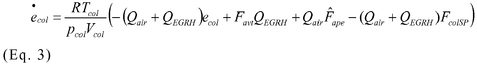
Notez que l'équation 3 est difficile à contrôler parce qu'elle varie avec le temps et présente une non linéarité dépendant de l'erreur de contrôle e col. Note that
Pour gérer la complexité de cette équation, on utilise des stratégies de contrôle avancées qui permettent d'assurer la convergence du système pour toutes les conditions d'opération du moteur. Plus précisément on va utiliser la commande linéaire à paramètres variant LPV (acronyme anglophone pour « Linéaire Paramètres Variants »).To manage the complexity of this equation, advanced control strategies are used to ensure the convergence of the system for all operating conditions of the engine. More precisely we will use the linear command to parameters varying LPV (acronym for "Linear Parameters Variants").
L'équation 3 peut se récrire sous forme LPV en appliquant la définition suivante pour le débit du circuit d'EGR à haute pression. 
Avec uv : une entrée de contrôle virtuel.With u v : a virtual control entry.
En combinant l'équation 3 et l'équation 4, on obtient le système LPV suivant. ![]()
![]()
Avec : ![]()


![]()
![]()
![]()
![]()
![]()
Avec les extrémités des paramètres ρ1 et ρ2 on crée un polytope, un espace convexe de paramètres, permettant de synthétiser un contrôleur de la forme : ![]()
![]()
Avec :
- Kcr : gain constant qui assure la convergence de ecol dans le polytope défini.
- Le gain Kcr est calculé avec les inégalités linéaires matricielles (LMI) suivantes :

- K cr : constant gain which ensures the convergence of e col in the defined polytope.
- The gain K cr is calculated with the following linear matrix inequalities (LMI):
Où l'index i représente l'évaluation d'une matrice dans le sommet du polytope i.Where the index i represents the evaluation of a matrix in the top of the polytope i.
Le système d'équations 7 permet de minimiser la fonction de coût suivante : ![]()
![]()
Le débit du circuit d'EGR à haute pression est donc défini de la façon suivante : 
Le débit du circuit d'EGR à haute pression doit respecter les contraintes suivantes afin d'être cohérent physiquement. 
Si les contraintes Eq. 10 ne sont pas satisfaites, la consigne de Fcol n'est pas atteignable. On annule le débit du circuit d'EGR à haute pression.If the constraints Eq. 10 are not satisfied, the instruction of Fcol is not achievable. The flow of the high pressure EGR circuit is canceled.
Il est à noter que l'équation Eq. 9 donnant le débit du circuit d'EGR à haute pression comprend une commande en boucle ouverte correspondant au premier terme 
Le procédé de commande associé comprend les étapes suivantes, illustrées par la figure unique.The associated control method comprises the following steps, illustrated by the single figure.
Lors d'une première étape 1, on détermine la fraction d'air frais Fcol dans le collecteur d'admission en appliquant l'estimateur décrit dans le document
Lors d'une deuxième étape 2, on détermine la consigne de fraction d'air frais FcoISP. Cette consigne peut être issue d'une cartographie à deux dimensions, dépendant du régime du moteur et de la charge du moteur, par exemple le couple de consigne. Une telle cartographie peut être précalibrée au banc moteur en fonction des objectifs d'émission d'oxydes d'azote et de particules du moteur. Ainsi, pour chaque point de fonctionnement régime-charge du moteur, on détermine une valeur optimale de consigne de fraction d'air frais permettant de répondre aux objectifs de dépollution.In a
Lors d'une troisième étape 3, on détermine si les contraintes de l'équation Eq. 10 sont satisfaites, en fonction de la mesure de la sonde de richesse à l'échappement.In a
Si tel n'est pas le cas, on commande la fermeture du circuit d'EGR à haute pression Lors d'une quatrième étape 4.If this is not the case, the closing of the high-pressure EGR circuit is ordered during a
Si les contraintes de l'équation Eq. 10 sont satisfaites, le procédé se poursuit par une cinquième étape 5, au cours de laquelle on détermine l'erreur de contrôle ecol puis on estime le débit du circuit d'EGR à haute pression en appliquant l'équation Eq. 9 et on commande le circuit d'EGR à haute pression pour qu'il délivre le débit estimé.If the constraints of equation Eq. 10 are satisfied, the process continues with a
Avec l'estimation de la fraction d'air frais dans le collecteur d'admission, le procédé de commande de type mixte (en boucle ouverte et fermée) permet de contrôler la fraction d'air frais dans le collecteur d'admission avant et durant les phases de démarrage, en permettant la réduction des émissions NOx durant les phases de fort transitoire et de changement de rapport, tout en fixant une fraction d'air frais suffisamment élevée pour assurer la combustion.With the estimation of the fresh air fraction in the intake manifold, the mixed-type control method (open and closed loop) controls the fraction of fresh air in the intake manifold before and during the start-up phases, allowing the reduction of NOx emissions during the phases of strong transient and shifting, while fixing a fraction of fresh air sufficiently high to ensure combustion.
Claims (1)
caractérisé par le fait qu'il comprend les étapes suivantes :
characterized in that it comprises the following steps:
Applications Claiming Priority (1)
| Application Number | Priority Date | Filing Date | Title |
|---|---|---|---|
| FR1558977A FR3041382B1 (en) | 2015-09-23 | 2015-09-23 | METHOD FOR CONTROLLING AN INTERNAL COMBUSTION ENGINE OF A MOTOR VEHICLE |
Publications (1)
| Publication Number | Publication Date |
|---|---|
| EP3147491A1 true EP3147491A1 (en) | 2017-03-29 |
Family
ID=54478874
Family Applications (1)
| Application Number | Title | Priority Date | Filing Date |
|---|---|---|---|
| EP16190214.3A Withdrawn EP3147491A1 (en) | 2015-09-23 | 2016-09-22 | Method for controlling an internal combustion engine of a motor vehicle |
Country Status (2)
| Country | Link |
|---|---|
| EP (1) | EP3147491A1 (en) |
| FR (1) | FR3041382B1 (en) |
Families Citing this family (1)
| Publication number | Priority date | Publication date | Assignee | Title |
|---|---|---|---|---|
| US10480435B2 (en) * | 2018-03-21 | 2019-11-19 | GM Global Technology Operations LLC | EGR and reformate fraction estimation in a dedicated EGR engine |
Citations (7)
| Publication number | Priority date | Publication date | Assignee | Title |
|---|---|---|---|---|
| EP2290209A2 (en) * | 2009-08-31 | 2011-03-02 | International Engine Intellectual Property Company, LLC | Intake manifold oxygen control |
| EP2397676A1 (en) * | 2010-06-16 | 2011-12-21 | Honda Motor Co., Ltd. | EGR control apparatus for internal combustion engine |
| WO2012085443A1 (en) * | 2010-12-22 | 2012-06-28 | Renault S.A.S. | System and method for controlling an internal combustion engine for a motor vehicle in transit |
| FR2973441A1 (en) | 2011-04-04 | 2012-10-05 | Renault Sas | Method for acquiring composition of intake gas in air distributor of internal combustion engine of car, involves calculating estimated value of parameter relative to composition of intake gas using state observer |
| FR2979389A1 (en) * | 2011-08-29 | 2013-03-01 | Renault Sa | SYSTEM AND METHOD FOR CONTROLLING AN EXHAUST GAS RECIRCULATION INTERNAL COMBUSTION ENGINE FOR A MOTOR VEHICLE IN TRANSIENT OPERATION |
| US20140261350A1 (en) * | 2013-03-15 | 2014-09-18 | Cummins Inc. | Active control of one or more egr loops |
| EP2811140A1 (en) * | 2013-06-03 | 2014-12-10 | Renault S.A.S. | System and method for determining the mass fraction of fresh gas in the intake manifold of an internal combustion engine of a motor vehicle |
-
2015
- 2015-09-23 FR FR1558977A patent/FR3041382B1/en active Active
-
2016
- 2016-09-22 EP EP16190214.3A patent/EP3147491A1/en not_active Withdrawn
Patent Citations (7)
| Publication number | Priority date | Publication date | Assignee | Title |
|---|---|---|---|---|
| EP2290209A2 (en) * | 2009-08-31 | 2011-03-02 | International Engine Intellectual Property Company, LLC | Intake manifold oxygen control |
| EP2397676A1 (en) * | 2010-06-16 | 2011-12-21 | Honda Motor Co., Ltd. | EGR control apparatus for internal combustion engine |
| WO2012085443A1 (en) * | 2010-12-22 | 2012-06-28 | Renault S.A.S. | System and method for controlling an internal combustion engine for a motor vehicle in transit |
| FR2973441A1 (en) | 2011-04-04 | 2012-10-05 | Renault Sas | Method for acquiring composition of intake gas in air distributor of internal combustion engine of car, involves calculating estimated value of parameter relative to composition of intake gas using state observer |
| FR2979389A1 (en) * | 2011-08-29 | 2013-03-01 | Renault Sa | SYSTEM AND METHOD FOR CONTROLLING AN EXHAUST GAS RECIRCULATION INTERNAL COMBUSTION ENGINE FOR A MOTOR VEHICLE IN TRANSIENT OPERATION |
| US20140261350A1 (en) * | 2013-03-15 | 2014-09-18 | Cummins Inc. | Active control of one or more egr loops |
| EP2811140A1 (en) * | 2013-06-03 | 2014-12-10 | Renault S.A.S. | System and method for determining the mass fraction of fresh gas in the intake manifold of an internal combustion engine of a motor vehicle |
Non-Patent Citations (2)
| Title |
|---|
| BESSAI C ET AL: "VIRTUELLER SAUERSTOFF-SENSOR IM EINLASSKRÜMMER EINES DIESELMOTORS", MTZ, SPRINGER, vol. 72, no. 11, 1 November 2011 (2011-11-01), pages 874 - 880, XP001569845, ISSN: 0024-8525, DOI: 10.1365/S35146-011-0189-X * |
| WANG ET AL: "Air fraction estimation for multiple combustion mode diesel engines with dual-loop EGR systems", CONTROL ENGINEERING PRACTICE, PERGAMON PRESS, OXFORD, GB, vol. 16, no. 12, 1 December 2008 (2008-12-01), pages 1479 - 1486, XP024529877, ISSN: 0967-0661, [retrieved on 20080610], DOI: 10.1016/J.CONENGPRAC.2008.04.007 * |
Also Published As
| Publication number | Publication date |
|---|---|
| FR3041382B1 (en) | 2017-09-01 |
| FR3041382A1 (en) | 2017-03-24 |
Similar Documents
| Publication | Publication Date | Title |
|---|---|---|
| EP2211043A1 (en) | Method for controlling the gas mass trapped in a cylinder of a petrol engine with variable valve timing | |
| JP4667346B2 (en) | Control device for internal combustion engine | |
| EP2925987A1 (en) | Method for controlling a double-supercharged combustion engine | |
| EP2318680B1 (en) | Method for managing the exhaust gas circulation circuit of a petrol thermal engine and corresponding recirculation system | |
| JP5423817B2 (en) | Control device for internal combustion engine | |
| EP2956651B1 (en) | Method of determination of exhaust gas pressure upstream of a turbo charger and of gas flow amount passing through its turbine | |
| CN109154245B (en) | Device for reducing combustion instability of heat engine | |
| FR2956160A1 (en) | Method for controlling air loop in internal combustion engine i.e. diesel engine, of vehicle, involves estimating gas flow traversing valves from thermodynamic parameters of air loop | |
| FR2758590A1 (en) | DEVICE FOR CONTROLLING AN INTERNAL COMBUSTION ENGINE WITH IGNITION CONTROL AND DIRECT INJECTION | |
| EP3147491A1 (en) | Method for controlling an internal combustion engine of a motor vehicle | |
| EP2430298B1 (en) | Estimation of the nitrogen oxide (nox) concentration in an internal combustion engine | |
| FR3058464A1 (en) | AIR INJECTION SYSTEM IN A GAS EXHAUST CIRCUIT OF A SUPERIOR THERMAL MOTOR. | |
| FR2939475A1 (en) | Method for anti-pollution treatment of exhaust gas from drive train of motor vehicle, involves deducing correction of aeraulic curve of exhaust gas recirculation valve based on difference between measured and estimated operating quantities | |
| FR2938301A1 (en) | Exhaust gas recirculation regulating method for internal combustion engine i.e. oil engine, of internal combustion engine assembly, involves regulating recirculation of gas such that minimal flow rate is lower than set flow rate | |
| EP2751416B1 (en) | System and method for controlling an internal combustion engine of an automotive vehicle with high-pressure and low-pressure exhaust gas recirculation circuits in transient mode operation | |
| FR2947866A1 (en) | Method for controlling air flow injected in petrol engine connected to turbocharger in vehicle, involves controlling air flow injected in engine by correcting set value airflow, where set value airflow is compared with minimum air flow | |
| EP2655838B1 (en) | System and method for controlling an internal combustion engine for a motor vehicle in transit | |
| FR2923538A3 (en) | Turbine upstream pressure estimating system for supercharged oil engine of motor vehicle, has calculation units calculating expansion ratio of turbine from magnitude representing temperature variation to deduce upstream pressure of turbine | |
| EP3067539B1 (en) | Method for determining the rotational speed of the turbocharger of an internal combustion engine of a motor vehicle | |
| FR3088370A1 (en) | METHOD FOR CALCULATING A SET POINT OF A THERMAL ENGINE TURBOCHARGER | |
| FR3033641B1 (en) | METHOD FOR DETERMINING THE PRESSURE BEFORE THE TURBINE OF A TURBOCHARGER OF AN INTERNAL COMBUSTION ENGINE OF A MOTOR VEHICLE. | |
| EP3805544A1 (en) | Control of a supercharged spark ignition engine with low-pressure exhaust gas recirculation | |
| FR3132546A1 (en) | Method for controlling the flow rate in a partial exhaust gas recirculation duct at the inlet of an engine and associated device | |
| EP2531713B1 (en) | Method for desensitizing the air admission loop of a heat engine to the perturbations of the egr loop | |
| FR2858020A1 (en) | Internal combustion engine controlling process for vehicle, involves regulating airflow in exchanger and bypass, such that temperature of air in collector approaches predetermined value |
Legal Events
| Date | Code | Title | Description |
|---|---|---|---|
| PUAI | Public reference made under article 153(3) epc to a published international application that has entered the european phase |
Free format text: ORIGINAL CODE: 0009012 |
|
| AK | Designated contracting states |
Kind code of ref document: A1 Designated state(s): AL AT BE BG CH CY CZ DE DK EE ES FI FR GB GR HR HU IE IS IT LI LT LU LV MC MK MT NL NO PL PT RO RS SE SI SK SM TR |
|
| AX | Request for extension of the european patent |
Extension state: BA ME |
|
| STAA | Information on the status of an ep patent application or granted ep patent |
Free format text: STATUS: THE APPLICATION IS DEEMED TO BE WITHDRAWN |
|
| 18D | Application deemed to be withdrawn |
Effective date: 20170930 |