EP3147247A1 - Elevator braking control system - Google Patents
Elevator braking control system Download PDFInfo
- Publication number
- EP3147247A1 EP3147247A1 EP16275137.4A EP16275137A EP3147247A1 EP 3147247 A1 EP3147247 A1 EP 3147247A1 EP 16275137 A EP16275137 A EP 16275137A EP 3147247 A1 EP3147247 A1 EP 3147247A1
- Authority
- EP
- European Patent Office
- Prior art keywords
- control system
- brake
- ustop
- car
- elevator
- Prior art date
- Legal status (The legal status is an assumption and is not a legal conclusion. Google has not performed a legal analysis and makes no representation as to the accuracy of the status listed.)
- Withdrawn
Links
- 230000037361 pathway Effects 0.000 claims abstract description 10
- 230000004913 activation Effects 0.000 claims description 26
- 238000000034 method Methods 0.000 claims description 10
- 238000004891 communication Methods 0.000 claims description 8
- 230000000977 initiatory effect Effects 0.000 claims description 8
- 238000012544 monitoring process Methods 0.000 claims description 5
- 230000008569 process Effects 0.000 claims description 2
- 230000008867 communication pathway Effects 0.000 abstract 1
- 238000012546 transfer Methods 0.000 description 5
- 230000009471 action Effects 0.000 description 3
- 238000012545 processing Methods 0.000 description 2
- 239000003990 capacitor Substances 0.000 description 1
- 230000008859 change Effects 0.000 description 1
- 238000010586 diagram Methods 0.000 description 1
- 230000004907 flux Effects 0.000 description 1
- 239000000463 material Substances 0.000 description 1
- 238000012986 modification Methods 0.000 description 1
- 230000004048 modification Effects 0.000 description 1
- 230000000135 prohibitive effect Effects 0.000 description 1
- 238000004804 winding Methods 0.000 description 1
Images


Classifications
-
- B—PERFORMING OPERATIONS; TRANSPORTING
- B66—HOISTING; LIFTING; HAULING
- B66B—ELEVATORS; ESCALATORS OR MOVING WALKWAYS
- B66B1/00—Control systems of elevators in general
- B66B1/24—Control systems with regulation, i.e. with retroactive action, for influencing travelling speed, acceleration, or deceleration
- B66B1/28—Control systems with regulation, i.e. with retroactive action, for influencing travelling speed, acceleration, or deceleration electrical
- B66B1/32—Control systems with regulation, i.e. with retroactive action, for influencing travelling speed, acceleration, or deceleration electrical effective on braking devices, e.g. acting on electrically controlled brakes
-
- B—PERFORMING OPERATIONS; TRANSPORTING
- B66—HOISTING; LIFTING; HAULING
- B66B—ELEVATORS; ESCALATORS OR MOVING WALKWAYS
- B66B11/00—Main component parts of lifts in, or associated with, buildings or other structures
- B66B11/04—Driving gear ; Details thereof, e.g. seals
- B66B11/0407—Driving gear ; Details thereof, e.g. seals actuated by an electrical linear motor
-
- B—PERFORMING OPERATIONS; TRANSPORTING
- B66—HOISTING; LIFTING; HAULING
- B66B—ELEVATORS; ESCALATORS OR MOVING WALKWAYS
- B66B5/00—Applications of checking, fault-correcting, or safety devices in elevators
- B66B5/0006—Monitoring devices or performance analysers
- B66B5/0018—Devices monitoring the operating condition of the elevator system
-
- B—PERFORMING OPERATIONS; TRANSPORTING
- B66—HOISTING; LIFTING; HAULING
- B66B—ELEVATORS; ESCALATORS OR MOVING WALKWAYS
- B66B5/00—Applications of checking, fault-correcting, or safety devices in elevators
- B66B5/02—Applications of checking, fault-correcting, or safety devices in elevators responsive to abnormal operating conditions
- B66B5/04—Applications of checking, fault-correcting, or safety devices in elevators responsive to abnormal operating conditions for detecting excessive speed
-
- B—PERFORMING OPERATIONS; TRANSPORTING
- B66—HOISTING; LIFTING; HAULING
- B66B—ELEVATORS; ESCALATORS OR MOVING WALKWAYS
- B66B5/00—Applications of checking, fault-correcting, or safety devices in elevators
- B66B5/02—Applications of checking, fault-correcting, or safety devices in elevators responsive to abnormal operating conditions
- B66B5/04—Applications of checking, fault-correcting, or safety devices in elevators responsive to abnormal operating conditions for detecting excessive speed
- B66B5/06—Applications of checking, fault-correcting, or safety devices in elevators responsive to abnormal operating conditions for detecting excessive speed electrical
-
- B—PERFORMING OPERATIONS; TRANSPORTING
- B66—HOISTING; LIFTING; HAULING
- B66B—ELEVATORS; ESCALATORS OR MOVING WALKWAYS
- B66B9/00—Kinds or types of lifts in, or associated with, buildings or other structures
- B66B9/003—Kinds or types of lifts in, or associated with, buildings or other structures for lateral transfer of car or frame, e.g. between vertical hoistways or to/from a parking position
Definitions
- Self-propelled elevator systems also referred to as ropeless elevator systems
- are useful in certain applications e.g., high rise buildings
- the mass of the ropes for a roped system is prohibitive and/or there is a need for multiple elevator cars in a single hoistway.
- ropeless elevator systems it may be advantageous to actuate mechanical braking of the elevator car from the car itself.
- a communication link should exist between the car and the hoistway side to perform reliable braking operations. Improvements in elevator car braking control are desirable should such a communication link fail.
- the hoistway control system includes a Ustop manager configured to initiate a Ustop vehicle mode upon the loss of the continuous brake command signal.
- the method includes monitoring deceleration of the elevator car by the car control system after holding brake activation; and initiating secondary brake activation by the car control system if deceleration does not fall below a threshold value.
Landscapes
- Engineering & Computer Science (AREA)
- Automation & Control Theory (AREA)
- Structural Engineering (AREA)
- Mechanical Engineering (AREA)
- Civil Engineering (AREA)
- Elevator Control (AREA)
- Types And Forms Of Lifts (AREA)
Abstract
Description
- The present disclosure relates to elevator systems, and more particularly to an elevator braking control system.
- Self-propelled elevator systems, also referred to as ropeless elevator systems, are useful in certain applications (e.g., high rise buildings) where the mass of the ropes for a roped system is prohibitive and/or there is a need for multiple elevator cars in a single hoistway. For ropeless elevator systems, it may be advantageous to actuate mechanical braking of the elevator car from the car itself. Similarly, it may be advantageous to actuate or control the propulsion of the elevator car generally from the hoistway side for power distribution and other reasons. To realize both of these advantages, a communication link should exist between the car and the hoistway side to perform reliable braking operations. Improvements in elevator car braking control are desirable should such a communication link fail.
- An elevator control system configured to control an elevator car constructed and arranged to move along a hoistway defined by a stationary structure, the elevator control system according to one, non-limiting, embodiment of the present disclosure includes a pathway; a hoistway control system supported by the stationary structure and configured to send a continuous brake command signal over the pathway; and a car control system carried by the elevator car and configured to receive the continuous brake command signal and initiate a brake Ustop mode upon a loss of the brake command signal, and independent of the hoistway control system.
- Additionally to the foregoing embodiment, the car control system includes a brake manager having an electronic processor, a sensor configured to send a sensor signal to the brake manager, and a brake controller, and wherein the brake manager while in the brake Ustop mode is configured to process the sensor signal and, based on the sensor signal, output a Ustop holding brake activation command to the brake controller.
- In the alternative or additionally thereto, in the foregoing embodiment, the brake controller includes a holding brake constructed and arranged to activate upon receipt of the Ustop holding brake activation command.
- In the alternative or additionally thereto, in the foregoing embodiment, the sensor is a velocity sensor.
- In the alternative or additionally thereto, in the foregoing embodiment, the brake manager outputs the Ustop holding brake activation command when a velocity of the elevator car is below a pre-programmed threshold.
- In the alternative or additionally thereto, in the foregoing embodiment, the brake manager is configured to monitor elevator car deceleration via the velocity sensor after outputting the Ustop holding brake activation command.
- In the alternative or additionally thereto, in the foregoing embodiment, the brake controller includes a secondary brake constructed and arranged to activate upon a Ustop secondary brake activation command from the brake manager.
- In the alternative or additionally thereto, in the foregoing embodiment, the brake manager is configured to output the Ustop secondary brake activation command if deceleration of the elevator car after outputting the Ustop holding brake activation command is not below a pre-programmed threshold.
- In the alternative or additionally thereto, in the foregoing embodiment, the brake manager applies a pre-programmed algorithm.
- In the alternative or additionally thereto, in the foregoing embodiment, the continuous brake command signal includes a no brake command and an apply brake command.
- In the alternative or additionally thereto, in the foregoing embodiment, the pathway is wireless and the elevator car is ropeless.
- In the alternative or additionally thereto, in the foregoing embodiment, the hoistway control system includes a Ustop manager configured to initiate a Ustop vehicle mode upon the loss of the continuous brake command signal.
- In the alternative or additionally thereto, in the foregoing embodiment, the hoistway control system includes a plurality of inverters constructed and arranged to energize a plurality or respective coils of a linear propulsion motor, and wherein the Ustop manager is configured to send a Ustop command signal to the plurality of inverters to slow a speed of the elevator car when in the Ustop vehicle mode.
- In the alternative or additionally thereto, in the foregoing embodiment, the Ustop command signal is in accordance with a Ustop speed profile pre-programmed into the hoistway control system.
- In the alternative or additionally thereto, in the foregoing embodiment, the sensor is a position sensor.
- A method of operating a ropeless elevator control system according to another, non-limiting, embodiment includes initiating a brake Ustop mode of a car control system carried by an elevator car when no communication exists between the car control system and a hoistway control system located remotely from the elevator car; monitoring car velocity during the brake Ustop mode by the car control system; initiating holding brake activation by the car control system when the car velocity falls below a threshold velocity; and bringing the elevator car to a stop.
- Additionally to the foregoing embodiment, the method includes
initiating a Ustop vehicle mode by the hoistway control system when no communication exists between the car control system and the hoistway control system; and controlling the energization of a plurality of coils of a linear propulsion motor by the hoistway control system to decelerate the elevator car during the Ustop vehicle mode. - In the alternative or additionally thereto, in the foregoing embodiment, the elevator car is decelerated in accordance with a deceleration profile programed into the hoistway control system.
- In the alternative or additionally thereto, in the foregoing embodiment, control of energization of the plurality of coils is conducted through a plurality of inverters respectively associated with the plurality of coils.
- In the alternative or additionally thereto, in the foregoing embodiment, the method includes monitoring deceleration of the elevator car by the car control system after holding brake activation; and initiating secondary brake activation by the car control system if deceleration does not fall below a threshold value.
- The foregoing features and elements may be combined in various combinations without exclusivity, unless expressly indicated otherwise. These features and elements as well as the operation thereof will become more apparent in light of the following description and the accompanying drawings. However, it should be understood that the following description and drawings are intended to be exemplary in nature and non-limiting.
- Various features will become apparent to those skilled in the art from the following detailed description of the disclosed non-limiting embodiments. The drawings that accompany the detailed description can be briefly described as follows:
-
FIG. 1 depicts a multicar elevator system in an exemplary embodiment; -
FIG. 2 is a top down view of a car and portions of a linear propulsion system in an exemplary embodiment; -
FIG. 3 is a schematic of the linear propulsion system; -
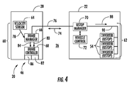
FIG. 4 is a schematic of car and hoistway control systems of the elevator system; and -
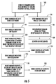
FIG. 5 is a block diagram of a method of operating an elevator control system having the car and hoistway control systems. -
FIG. 1 depicts a self-propelled orropeless elevator system 20 in an exemplary embodiment that may be used in a structure or building 22 having multiple levels orfloors 24.Elevator system 20 includes ahoistway 26 defined by boundaries carried by thestructure 22, and at least onecar 28 adapted to travel in thehoistway 26. Thehoistway 26 may include, for example, threelanes cars 28 traveling in any one lane and in any number of travel directions (e.g., up and down). For example and as illustrated, thecars 28 inlanes cars 28 inlane 32 may travel in a down direction. - Above the
top floor 24 may be anupper transfer station 36 that facilitates horizontal motion toelevator cars 28 for moving the cars betweenlanes first floor 24 may be alower transfer station 38 that facilitates horizontal motion toelevator cars 28 for moving the cars betweenlanes lower transfer stations first floors 24 rather than above and below the top and first floors, or may be located at any intermediate floor. Yet further, theelevator system 20 may include one or more intermediate transfer stations (not illustrated) located vertically between and similar to the upper andlower transfer stations - Referring to
FIGS. 1 through 3 , thecars 28 are propelled using alinear propulsion system 40 that may have twolinear propulsion motors 41 that may be generally positioned on opposite sides of theelevator cars 28, and a control system 46 (seeFIG. 3 ). Eachmotor 41 may include a fixedprimary portion 42 generally mounted to thebuilding 22, and a movingsecondary portion 44 mounted to theelevator car 28. Theprimary portion 42 includes a plurality of windings orcoils 48 that generally form a row extending longitudinally along and projecting laterally into each of thelanes secondary portion 44 may include two rows of opposingpermanent magnets car 28. The plurality ofcoils 48 of theprimary portion 42 are generally located between and spaced from the opposing rows ofpermanent magnets Primary portion 42 is supplied with drive signals from thecontrol system 46 to generate a magnetic flux that imparts a force on thesecondary portions 44 to control movement of thecars 28 in theirrespective lanes secondary portions 44 may be mounted to thecar 28, and any number ofprimary portions 42 may be associated with thesecondary portions 44 in any number of configurations. It is further understood that each lane may be associated with only onelinear propulsion motor 41 or three ormore motors 41. Yet further, the primary andsecondary portions - Referring to
FIG. 3 , thecontrol system 46 may includepower sources 52, drives 54 (i.e., inverters),buses 56 and acontroller 58. Thepower sources 52 are electrically coupled to thedrives 54 via thebuses 56. In one non-limiting example, thepower sources 52 may be direct current (DC) power sources.DC power sources 52 may be implemented using storage devices (e.g., batteries, capacitors), and may be active devices that condition power from another source (e.g., rectifiers). Thedrives 54 may receive DC power from thebuses 56 and may provide drive signals to theprimary portions 42 of thelinear propulsion system 40. Eachdrive 54 may be an inverter that converts DC power frombus 56 to a multiphase (e.g., three phase) drive signal provided to a respective section of theprimary portions 42. Theprimary portion 42 may be divided into a plurality of modules or sections, with each section associated with arespective drive 54. - The
controller 58 provides control signals to each of thedrives 54 to control generation of the drive signals. Thecontroller 58 may provide thrust commands from a motion regulator (not shown) to control generation of the drive signals by thedrives 54. The drive output may be a pulse width modulation (PWM).Controller 58 may be implemented using a processor-based device programmed to generate the control signals. Thecontroller 58 may also be part of an elevator control system or elevator management system. Elements of thecontrol system 46 may be implemented in a single, integrated module, and/or may be distributed along thehoistway 26. - Referring to
FIG. 4 , thecontrol system 46 may further include acar control system 60 carried by eachelevator car 28 and ahoistway control system 62 located remotely from the elevator car and generally supported, at least in-part, by thestationary structure 22. Thecar control system 60 includes asensor 64, abrake manager 66, and abrake controller 68. Thehoistway control system 62 may include aUstop manager 70, avehicle control 72 and the plurality of inverters 54 (also seeFIG. 3 ). TheUstop manager 70 and/or thevehicle control 72 may be an integral part of thecontroller 58. Duringnormal elevator car 28 operation, a continuous brake command signal (see arrow 74) is sent between thebrake manager 66 and theUstop manger 70 via apathway 76 that may be wireless. The continuousbrake command signal 74 may generally include a no brake command and an apply brake command. The term 'Ustop", or Ustop action, refers to an urgent stop, which is initiated when the system determines that it may be undesirable for the elevator to continue moving along a planned velocity profile. In general, a Ustop action may be accomplished through either controlling elevator motor(s), and/or engaging one or more braking devices. - The
brake manager 66 may include an electronic processor and a computer readable storage medium for receiving and processing car velocity signals (see arrow 78) received from thevelocity sensor 64 and comparing such data to pre-programed velocity and/or deceleration profiles, via, for example, a pre-programmed algorithm. Based on processing of the velocity signals 78 by thebrake manager 66, thebrake controller 68 may receive a Ustop holding brake activation command signal (see arrow 80) to activate a holdingbrake 82 from thebrake manager 66. Also based on velocity signals 78, thebrake controller 68 may receive a Ustop secondary brake activation command signal (see arrow 84) to activate asecondary brake 86 from thebrake manager 66. It is further contemplated and understood that thesensor 64 may be a type of position sensor which is used to calculate velocity by viewing change in car position over a period of time. It is further understood that the holding brakeactivation command signal 80 may generally be the same signal applied during normal operation (i.e., not just Ustop operation). Moreover, the holding and secondary brakes may be operated by different brake controllers, and the holding brake may be a plurality of brakes applied selectively to control elevator car deceleration. - The
Ustop manager 70 of thehoistway control system 62 generally makes the determination of when Ustop action is needed (i.e., any variety of unsafe conditions is detected). In the present disclosure, the unsafe condition is the loss of communication (e.g., signal 74) between the car andhoistway control systems Ustop manager 70 may include an electronic processor and a computer readable storage medium configured to output a Ustop command signal (see arrow 88) to the plurality ofinverters 54 over apathway 90. TheUstop manager 70 control of the plurality ofinverters 54 during a Ustop mode of operation may be based, at least in-part, on a pre-programmed deceleration profile. TheUstop manager 70 may utilize a pre-programmed algorithm to, at least in-part, compare actual deceleration of theelevator car 28 to the deceleration profile. The Ustop command signal is either on or off. The progress of the elevator car may be monitored during the Ustop mode, but (as one, non-limiting, example) the only commands that may be issued to theinverters 54 is to go into the Ustop mode. There may be no other coordination needed between drives for this operation. Thepathway 90 may be wired or wireless. - Referring to
FIGS. 4 and5 , upon a loss of communication between the car andhoistway control systems 60, 62 (e.g., failure of the continuousbrake command signal 74, seeblock 100 inFIG. 5 ), thebrake manager 66 of thecar control system 60 may initiate the brake Ustop mode (see block 102). Independently and what may be simultaneously, theUstop manager 70 of thehoistway control system 62 may initiate a vehicle Ustop mode (see block 104). When in the vehicle Ustop mode, theUstop manager 70 may send a deceleration command signal 88 (i.e., the Ustop command signal) to the plurality of inverters 54 (see block 106) resulting in deceleration of the elevator car 28 (see block 108). The term 'brake Ustop' generally refers to a stopping means that deploys a braking device that may act on guide rails, and does not rely on a propulsion and/or motorized system. - When the
hoistway control system 62 is in the vehicle Ustop mode, thecar control system 60 may be in the brake Ustop mode. When in the brake Ustop mode, thebrake manager 66 monitors the velocity of the car 28 (see block 110) in preparation of applying the holdingbrake 82 without creating excessive G-forces. Although functioning independently, during this monitoring time span, theelevator car 28 may be decelerating due to the deceleration command from theUstop manager 70 to the plurality ofinverters 54. When the velocity falls below a threshold pre-programmed into thebrake manager 66, the brake manager outputs a holding brakeactivation command signal 80 to the brake controller 68 (see block 112). Upon receipt, thebrake controller 68 may activate the holding brake 82 (see block 114) to bring theelevator car 28 to a relatively quick or urgent stop. - After sending the holding brake
activation command signal 80, thebrake manager 66 may continue to monitor deceleration of the elevator car 28 (see block 116). After a pre-programmed time period, if the deceleration does not meet a pre-programmed threshold, thebrake manager 66 may output a secondary brakeactivation command signal 84 to the brake controller 68 (see block 118). Upon receipt, thebrake controller 68 may activate a secondary brake 86 (see block 120) to further decelerate theelevator car 28. - While the present disclosure is described with reference to exemplary embodiments, it will be understood by those skilled in the art that various changes may be made and equivalents may be substituted without departing from the spirit and scope of the present disclosure. In addition, various modifications may be applied to adapt the teachings of the present disclosure to particular situations, applications, and/or materials, without departing from the essential scope thereof. For example, the elevator system may not be a ropeless elevator system, and may apply to any type of elevator system including cabled elevator systems. The present disclosure is thus not limited to the particular examples disclosed herein, but includes all embodiments falling within the scope of the appended claims.
Claims (15)
- An elevator control system configured to control an elevator car constructed and arranged to move along a hoistway defined by a stationary structure, the elevator control system comprising:a pathway;a hoistway control system supported by the stationary structure and configured to send a continuous brake command signal over the pathway; anda car control system carried by the elevator car and configured to receive the continuous brake command signal and initiate a brake Ustop mode upon a loss of the brake command signal, and independent of the hoistway control system.
- The elevator control system set forth in claim 1, wherein the car control system includes a brake manager having an electronic processor, a sensor configured to send a sensor signal to the brake manager, and a brake controller, and wherein the brake manager while in the brake Ustop mode is configured to process the sensor signal and, based on the sensor signal, output a Ustop holding brake activation command to the brake controller; and preferably
wherein the brake controller includes a holding brake constructed and arranged to activate upon receipt of the Ustop holding brake activation command. - The elevator control system set forth in claim 2, wherein the sensor is a velocity sensor; and preferably
wherein the brake manager outputs the Ustop holding brake activation command when a velocity of the elevator car is below a pre-programmed threshold. - The elevator control system set forth in claim 3, wherein the brake manager is configured to monitor elevator car deceleration via the velocity sensor after outputting the Ustop holding brake activation command.
- The elevator control system set forth in claim 4, wherein the brake controller includes a secondary brake constructed and arranged to activate upon a Ustop secondary brake activation command from the brake manager; and preferably
wherein the brake manager is configured to output the Ustop secondary brake activation command if deceleration of the elevator car after outputting the Ustop holding brake activation command is not below a pre-programmed threshold. - The elevator control system set forth in claim 5, wherein the brake manager applies a pre-programmed algorithm.
- The elevator control system set forth in any preceding claim, wherein the continuous brake command signal includes a no brake command and an apply brake command.
- The elevator control system set forth in any preceding claim, wherein the pathway is wireless and the elevator car is ropeless.
- The elevator control system set forth in any preceding claim, wherein the hoistway control system includes a Ustop manager configured to initiate a Ustop vehicle mode upon the loss of the continuous brake command signal.
- The elevator control system set forth in claim 9, wherein the hoistway control system includes a plurality of inverters constructed and arranged to energize a plurality or respective coils of a linear propulsion motor, and wherein the Ustop manager is configured to send a Ustop command signal to the plurality of inverters to slow a speed of the elevator car when in the Ustop vehicle mode; and preferably
wherein the Ustop command signal is in accordance with a Ustop speed profile pre-programmed into the hoistway control system. - The elevator control system set forth in claim 2, wherein the sensor is a position sensor.
- A method of operating a ropeless elevator control system comprising:initiating a brake Ustop mode of a car control system carried by an elevator car when no communication exists between the car control system and a hoistway control system located remotely from the elevator car;monitoring car velocity during the brake Ustop mode by the car control system;initiating holding brake activation by the car control system when the car velocity falls below a threshold velocity; andbringing the elevator car to a stop.
- The method set forth in claim 12 further comprising:initiating a Ustop vehicle mode by the hoistway control system when no communication exists between the car control system and the hoistway control system; andcontrolling the energization of a plurality of coils of a linear propulsion motor by the hoistway control system to decelerate the elevator car during the Ustop vehicle mode; and preferablywherein the elevator car is decelerated in accordance with a deceleration profile programed into the hoistway control system.
- The method set forth in claim 13, wherein control of energization of the plurality of coils is conducted through a plurality of inverters respectively associated with the plurality of coils.
- The method set forth in any of claims 12 to 14 further comprising:monitoring deceleration of the elevator car by the car control system after holding brake activation; andinitiating secondary brake activation by the car control system if deceleration does not fall below a threshold value.
Applications Claiming Priority (1)
| Application Number | Priority Date | Filing Date | Title |
|---|---|---|---|
| US201562219503P | 2015-09-16 | 2015-09-16 |
Publications (1)
| Publication Number | Publication Date |
|---|---|
| EP3147247A1 true EP3147247A1 (en) | 2017-03-29 |
Family
ID=56939981
Family Applications (1)
| Application Number | Title | Priority Date | Filing Date |
|---|---|---|---|
| EP16275137.4A Withdrawn EP3147247A1 (en) | 2015-09-16 | 2016-09-15 | Elevator braking control system |
Country Status (5)
| Country | Link |
|---|---|
| US (1) | US10407273B2 (en) |
| EP (1) | EP3147247A1 (en) |
| KR (1) | KR20170033256A (en) |
| CN (1) | CN106542392B (en) |
| AU (1) | AU2016228238C1 (en) |
Families Citing this family (12)
| Publication number | Priority date | Publication date | Assignee | Title |
|---|---|---|---|---|
| CN105960370A (en) * | 2013-12-05 | 2016-09-21 | 奥的斯电梯公司 | Motor drive for linear machines with distributed windings |
| DE102014201804A1 (en) * | 2014-01-31 | 2015-08-06 | Thyssenkrupp Elevator Ag | Method for operating an elevator system |
| US10017354B2 (en) * | 2015-07-10 | 2018-07-10 | Otis Elevator Company | Control system for multicar elevator system |
| AU2016231585B2 (en) * | 2015-09-25 | 2018-08-09 | Otis Elevator Company | Elevator component separation assurance system and method of operation |
| SG11201805570WA (en) | 2015-12-30 | 2018-07-30 | Corium Int Inc | Systems and methods for long term transdermal administration |
| US10427908B2 (en) * | 2016-04-15 | 2019-10-01 | Otis Elevator Company | Emergency mode operation of elevator system having linear propulsion system |
| US10081513B2 (en) * | 2016-12-09 | 2018-09-25 | Otis Elevator Company | Motion profile for empty elevator cars and occupied elevator cars |
| DE102017109727A1 (en) * | 2017-05-05 | 2018-11-08 | Thyssenkrupp Ag | Control system for an elevator installation, elevator installation and method for controlling an elevator installation |
| KR102106579B1 (en) * | 2017-10-31 | 2020-05-28 | 숭실대학교산학협력단 | Non-contact vertical transportation system using linear motors |
| CN108147240B (en) * | 2017-12-06 | 2019-06-21 | 天津市特种设备监督检验技术研究院(天津市特种设备事故应急调查处理中心) | A kind of digitized elevator brake ability monitoring and method for early warning |
| US20220177274A1 (en) * | 2020-12-04 | 2022-06-09 | Otis Elevator Company | Ropeless elevator vehicle workstation |
| DE102021125143A1 (en) | 2021-09-28 | 2023-03-30 | Tk Elevator Innovation And Operations Gmbh | Apparatus and method for powering a ropeless linear drive elevator system and use |
Citations (4)
| Publication number | Priority date | Publication date | Assignee | Title |
|---|---|---|---|---|
| US5377786A (en) * | 1991-06-13 | 1995-01-03 | Kabushiki Kaisha Toshiba | Elevator with a governor |
| US6170614B1 (en) * | 1998-12-29 | 2001-01-09 | Otis Elevator Company | Electronic overspeed governor for elevators |
| GB2402383A (en) * | 2003-06-02 | 2004-12-08 | Michael Godwin | Electromagnetic retarder for linear motor elevators |
| US20120000732A1 (en) * | 2009-03-16 | 2012-01-05 | Otis Elevator Company | Electromagnetic safety trigger |
Family Cites Families (22)
| Publication number | Priority date | Publication date | Assignee | Title |
|---|---|---|---|---|
| JPS58144071A (en) * | 1982-02-23 | 1983-08-27 | 三菱電機株式会社 | Controller for elevator |
| JPS601558A (en) | 1983-06-20 | 1985-01-07 | Sumitomo Metal Ind Ltd | Method and apparatus for automatic sampling of molten iron |
| JPH0764493B2 (en) * | 1988-06-27 | 1995-07-12 | 三菱電機株式会社 | Elevator control equipment |
| JPH072037B2 (en) * | 1989-07-03 | 1995-01-11 | 日本オーチス・エレベータ株式会社 | Inverter control device for elevator drive |
| JP3278200B2 (en) | 1992-06-23 | 2002-04-30 | 三菱電機株式会社 | Elevator data transmission equipment |
| US5751076A (en) | 1996-01-19 | 1998-05-12 | Inventio Ag | Drive system for lifts |
| FI108025B (en) | 1997-06-19 | 2001-11-15 | Kone Corp | Elevator |
| EP1401755A1 (en) * | 2001-06-14 | 2004-03-31 | Thyssen Elevator Capital Corp. | Drive system for multiple elevator cars in a single shaft |
| US20060163008A1 (en) | 2005-01-24 | 2006-07-27 | Michael Godwin | Autonomous linear retarder/motor for safe operation of direct drive gearless, rope-less elevators |
| JP4824424B2 (en) | 2006-02-21 | 2011-11-30 | オークマ株式会社 | Linear motor |
| GB2437949A (en) | 2006-05-10 | 2007-11-14 | Michael Godwin | Electromagnetic retarder for passenger platform hoist |
| ES2499340T3 (en) | 2007-08-07 | 2014-09-29 | Thyssenkrupp Elevator Ag | Elevator system |
| GB0817076D0 (en) | 2008-09-17 | 2008-10-22 | Godwin Adrian | Autonomous capsule |
| DE102009048822A1 (en) | 2009-10-09 | 2011-04-14 | Siemens Aktiengesellschaft | Transport system with electromagnetic brake |
| FI20105033L (en) * | 2010-01-18 | 2011-07-19 | Kone Corp | Method for monitoring the movement of an elevator car and an elevator system |
| DE102011009006A1 (en) | 2011-01-20 | 2012-07-26 | Schlenk Metallfolien Gmbh & Co. Kg | Method for producing pre-tinned connectors for PV cells |
| US10087044B2 (en) | 2013-01-17 | 2018-10-02 | Otis Elevator Company | Enhanced deceleration propulsion system for elevators |
| WO2014123515A1 (en) | 2013-02-06 | 2014-08-14 | Otis Elevator Company | Self-propelled cargo lift for elevator systems |
| WO2014189492A1 (en) | 2013-05-21 | 2014-11-27 | Otis Elevator Company | Wireless power supply for self-propelled elevator |
| US20160297648A1 (en) | 2013-12-05 | 2016-10-13 | Otis Elevator Company | Stator reduction in ropeless elevator transfer station |
| EP3253703B1 (en) * | 2015-02-05 | 2019-04-10 | Otis Elevator Company | Ropeless elevator control system |
| JP6710226B2 (en) * | 2015-06-26 | 2020-06-17 | コネ コーポレイションKone Corporation | Linear motor elevator |
-
2016
- 2016-09-14 CN CN201610825936.7A patent/CN106542392B/en active Active
- 2016-09-15 EP EP16275137.4A patent/EP3147247A1/en not_active Withdrawn
- 2016-09-15 AU AU2016228238A patent/AU2016228238C1/en not_active Ceased
- 2016-09-15 US US15/266,452 patent/US10407273B2/en active Active
- 2016-09-19 KR KR1020160119475A patent/KR20170033256A/en not_active Withdrawn
Patent Citations (4)
| Publication number | Priority date | Publication date | Assignee | Title |
|---|---|---|---|---|
| US5377786A (en) * | 1991-06-13 | 1995-01-03 | Kabushiki Kaisha Toshiba | Elevator with a governor |
| US6170614B1 (en) * | 1998-12-29 | 2001-01-09 | Otis Elevator Company | Electronic overspeed governor for elevators |
| GB2402383A (en) * | 2003-06-02 | 2004-12-08 | Michael Godwin | Electromagnetic retarder for linear motor elevators |
| US20120000732A1 (en) * | 2009-03-16 | 2012-01-05 | Otis Elevator Company | Electromagnetic safety trigger |
Also Published As
| Publication number | Publication date |
|---|---|
| US20170073183A1 (en) | 2017-03-16 |
| KR20170033256A (en) | 2017-03-24 |
| AU2016228238C1 (en) | 2018-06-21 |
| US10407273B2 (en) | 2019-09-10 |
| CN106542392B (en) | 2020-09-15 |
| AU2016228238B2 (en) | 2018-03-22 |
| AU2016228238A1 (en) | 2017-03-30 |
| CN106542392A (en) | 2017-03-29 |
Similar Documents
| Publication | Publication Date | Title |
|---|---|---|
| AU2016228238B2 (en) | Elevator braking control system | |
| US10421642B2 (en) | Elevator component separation assurance system and method of operation | |
| US10934130B2 (en) | Elevator control system | |
| EP3118149B1 (en) | Control system for multicar elevator system | |
| US9840395B2 (en) | Multi-drive thrust manager for elevator control | |
| US20170066623A1 (en) | Ropeless elevator control system | |
| US10745238B2 (en) | Power distribution for multicar, ropeless elevator system | |
| EA036670B1 (en) | Elevator with linear motor | |
| US20180037437A1 (en) | Elevator run profile modification for smooth rescue | |
| US20190100406A1 (en) | Elevator short-range communication system | |
| EP3954640A1 (en) | Intercar coordination in multicar hoistways | |
| HK1236022A1 (en) | Elevator braking control system | |
| US10399815B2 (en) | Car separation control in multi-car elevator system | |
| HK1228877B (en) | Control system for multicar elevator system | |
| HK1243050B (en) | Elevator component separation assurance system and method of operation | |
| HK1243050A1 (en) | Elevator component separation assurance system and method of operation |
Legal Events
| Date | Code | Title | Description |
|---|---|---|---|
| PUAI | Public reference made under article 153(3) epc to a published international application that has entered the european phase |
Free format text: ORIGINAL CODE: 0009012 |
|
| STAA | Information on the status of an ep patent application or granted ep patent |
Free format text: STATUS: THE APPLICATION HAS BEEN PUBLISHED |
|
| AK | Designated contracting states |
Kind code of ref document: A1 Designated state(s): AL AT BE BG CH CY CZ DE DK EE ES FI FR GB GR HR HU IE IS IT LI LT LU LV MC MK MT NL NO PL PT RO RS SE SI SK SM TR |
|
| AX | Request for extension of the european patent |
Extension state: BA ME |
|
| RAP1 | Party data changed (applicant data changed or rights of an application transferred) |
Owner name: OTIS ELEVATOR COMPANY |
|
| STAA | Information on the status of an ep patent application or granted ep patent |
Free format text: STATUS: REQUEST FOR EXAMINATION WAS MADE |
|
| 17P | Request for examination filed |
Effective date: 20170929 |
|
| RBV | Designated contracting states (corrected) |
Designated state(s): AL AT BE BG CH CY CZ DE DK EE ES FI FR GB GR HR HU IE IS IT LI LT LU LV MC MK MT NL NO PL PT RO RS SE SI SK SM TR |
|
| STAA | Information on the status of an ep patent application or granted ep patent |
Free format text: STATUS: THE APPLICATION IS DEEMED TO BE WITHDRAWN |
|
| 18D | Application deemed to be withdrawn |
Effective date: 20200603 |