EP3147140A1 - Pneumatic tire - Google Patents
Pneumatic tire Download PDFInfo
- Publication number
- EP3147140A1 EP3147140A1 EP15795565.9A EP15795565A EP3147140A1 EP 3147140 A1 EP3147140 A1 EP 3147140A1 EP 15795565 A EP15795565 A EP 15795565A EP 3147140 A1 EP3147140 A1 EP 3147140A1
- Authority
- EP
- European Patent Office
- Prior art keywords
- groove wall
- outside
- tread
- wall surface
- angle
- Prior art date
- Legal status (The legal status is an assumption and is not a legal conclusion. Google has not performed a legal analysis and makes no representation as to the accuracy of the status listed.)
- Granted
Links
- 238000009434 installation Methods 0.000 claims abstract description 52
- 230000000052 comparative effect Effects 0.000 description 9
- XLYOFNOQVPJJNP-UHFFFAOYSA-N water Substances O XLYOFNOQVPJJNP-UHFFFAOYSA-N 0.000 description 9
- 238000011156 evaluation Methods 0.000 description 5
- 230000001105 regulatory effect Effects 0.000 description 4
- 230000015556 catabolic process Effects 0.000 description 3
- 238000006731 degradation reaction Methods 0.000 description 3
- 239000012141 concentrate Substances 0.000 description 2
- 230000000593 degrading effect Effects 0.000 description 2
- 230000007423 decrease Effects 0.000 description 1
- 230000000694 effects Effects 0.000 description 1
- 230000005764 inhibitory process Effects 0.000 description 1
Images


Classifications
-
- B—PERFORMING OPERATIONS; TRANSPORTING
- B60—VEHICLES IN GENERAL
- B60C—VEHICLE TYRES; TYRE INFLATION; TYRE CHANGING; CONNECTING VALVES TO INFLATABLE ELASTIC BODIES IN GENERAL; DEVICES OR ARRANGEMENTS RELATED TO TYRES
- B60C11/00—Tyre tread bands; Tread patterns; Anti-skid inserts
- B60C11/03—Tread patterns
- B60C11/13—Tread patterns characterised by the groove cross-section, e.g. for buttressing or preventing stone-trapping
- B60C11/1307—Tread patterns characterised by the groove cross-section, e.g. for buttressing or preventing stone-trapping with special features of the groove walls
- B60C11/1323—Tread patterns characterised by the groove cross-section, e.g. for buttressing or preventing stone-trapping with special features of the groove walls asymmetric
-
- B—PERFORMING OPERATIONS; TRANSPORTING
- B60—VEHICLES IN GENERAL
- B60C—VEHICLE TYRES; TYRE INFLATION; TYRE CHANGING; CONNECTING VALVES TO INFLATABLE ELASTIC BODIES IN GENERAL; DEVICES OR ARRANGEMENTS RELATED TO TYRES
- B60C11/00—Tyre tread bands; Tread patterns; Anti-skid inserts
- B60C11/03—Tread patterns
- B60C11/0302—Tread patterns directional pattern, i.e. with main rolling direction
-
- B—PERFORMING OPERATIONS; TRANSPORTING
- B60—VEHICLES IN GENERAL
- B60C—VEHICLE TYRES; TYRE INFLATION; TYRE CHANGING; CONNECTING VALVES TO INFLATABLE ELASTIC BODIES IN GENERAL; DEVICES OR ARRANGEMENTS RELATED TO TYRES
- B60C11/00—Tyre tread bands; Tread patterns; Anti-skid inserts
- B60C11/03—Tread patterns
- B60C11/0304—Asymmetric patterns
-
- B—PERFORMING OPERATIONS; TRANSPORTING
- B60—VEHICLES IN GENERAL
- B60C—VEHICLE TYRES; TYRE INFLATION; TYRE CHANGING; CONNECTING VALVES TO INFLATABLE ELASTIC BODIES IN GENERAL; DEVICES OR ARRANGEMENTS RELATED TO TYRES
- B60C11/00—Tyre tread bands; Tread patterns; Anti-skid inserts
- B60C11/03—Tread patterns
- B60C11/13—Tread patterns characterised by the groove cross-section, e.g. for buttressing or preventing stone-trapping
-
- B—PERFORMING OPERATIONS; TRANSPORTING
- B60—VEHICLES IN GENERAL
- B60C—VEHICLE TYRES; TYRE INFLATION; TYRE CHANGING; CONNECTING VALVES TO INFLATABLE ELASTIC BODIES IN GENERAL; DEVICES OR ARRANGEMENTS RELATED TO TYRES
- B60C5/00—Inflatable pneumatic tyres or inner tubes
Definitions
- the present invention relates to a pneumatic tire.
- Patent Document 1 listed below discloses a pneumatic tire whose stiffness against a lateral input force is improved by increasing a volume of rubber by increasing a minimum curvature radius of an outside curved portion of an inner surface of a groove.
- the "installation outer/inner side” is an outer/inner side with respect to a body of a vehicle when the tire T10 is installed on the vehicle.
- the “outside/inside curved portion” is similar thereto. According to these configurations, reduction of a lateral input force at edges of land portions (blocks and ribs) 104 is restricted and thereby a larger lateral force is generated, so that dynamic performance and handling stability are improved.
- Patent Document 1 EP 1 926 610 B1
- An object of the present invention is to provide a pneumatic tire that can effectively resist a lateral input force from an installation outer side during cornering and thereby can restrict an inclining deformation of a land portion to improve handling stability.
- An aspect of the present invention provides a pneumatic tire comprising: a tread that has a tread surface; a plurality of circumferential main grooves that are formed on the tread; and a plurality of land portions that are formed, on the tread, between the plurality of circumferential main grooves, wherein each of the plurality of circumferential main grooves has, in a lateral cross-sectional view, a groove bottom surface, an outside groove wall surface located on an installation outer side, an inside groove wall surface located on an installation inner side, an outside curved portion connecting the groove bottom surface with the outside groove wall surface, and an inside curved portion connecting the groove bottom surface with the inside groove wall surface, (a minimum curvature radius of the outside curved portion) > (a minimum curvature radius of the inside curved portion) is satisfied in the lateral cross-sectional view, and, when, in the lateral cross-sectional view, an angle of the outside groove wall surface to a tread normal line at a border edge between the outside groove wall surface and the tread surface is denoted as a
- the "regulated inner pressure” denotes an air pressure regulated according to a maximum load rating in a Standard.
- the "applied rim” denotes a rim regulated according to a tire size in the Standard.
- the above-mentioned Standard denotes " JATMA YEAR BOOK (here, 2008 editi on)" issued by the Japan Automobile Tyre Manufacturers Association. Note that, in a case where the TRA Standard, the ETRTO Standard or the like is applied in a region where it is used or manufactured, the above-mentioned Standard should comply with each of the Standards.
- a tread 10 of the pneumatic tire T1 includes plural circumferential main grooves 50A extending in a tire circumferential direction, and plural land portions 11 and 12 divided by the circumferential main grooves 50A.
- the "land portions” include blocks and ribs on the tread 10.
- the three land portions (ribs) 11 is formed, by the three circumferential main grooves 50A, at a central region of the tread 10.
- a pair of the land portions 12 is formed at both side regions of the tread 10.
- a tread pattern is formed by these land portions 11 and 12 (and small grooves formed on the land portions 11 and 12) and the circumferential main grooves 50A.
- the land portion 11 is formed so as to be interposed between the circumferential main grooves 50A, and the circumferential main groove 50A has a groove bottom surface 51, groove wall surfaces 52 (52a and 52b), and curved portions (groove bottom corners) 53 (53a and 53b) connecting the groove bottom surface 51 with the groove wall surfaces 52.
- the groove bottom surface 51 and the groove wall surfaces 52 are formed flat, but not limited to be flat.
- the groove bottom surface 51 and the groove wall surfaces 52 may be formed to be curved with a curvature radius larger than a curvature radius of the curved portions 53.
- the curved portions 53 includes an outside curved portion 53a on an installation outer side and an inside curved portion 53b on an installation inner side.
- a minimum curvature radius R1 of the outside curved portion 53a > (a minimum curvature radius R2 of the inside curved portion 53b) is satisfied.
- the reason why the "minimum" curvature radius is used here is that the curved portion 53 (53a or 53b) may be formed with a uniform curvature radius, or may be formed so that its curvature radius varies continuously.
- each of the curved portions 53 (53a or 53b) is formed with a uniform curvature radius so as to connect the flat groove bottom surface 51 continuously with the flat groove wall surface 52 (52a or 52b).
- the cross-sectional groove view (the cross-sectional view along the width direction)
- angles (groove wall angles) of the groove wall surfaces 52 to a tread normal line (s) N at border edges between the groove wall surfaces 52 and a tread surface 60 an inequality (the groove wall angle ⁇ on the installation outer side) ⁇ (the groove wall angle ⁇ on the installation inner side) is satisfied.
- the angle of the outside groove wall surface 52a to the tread normal line N at the border edge between the outside groove wall surface 52a and the tread surface 60a is the groove wall angle ⁇ ( ⁇ 0).
- the angle of the inside groove wall surface 52b to the tread normal line N at the border edge between the inside groove wall surface 52b and the tread surface 60b is the groove wall angle ⁇ ( ⁇ 0).
- the minimum curvature radius R1 of the outside curved portion 53a is not more than twice the minimum curvature radius R2 of the inside curved portion 53b.
- the groove wall angles on the installation inner side is in a range from (the groove wall angle ⁇ on the installation outer side + 2°) to ( ⁇ +30°) [i.e. (a+2°) ⁇ ( ⁇ +30°)], and it is more preferable that it is in a range from ( ⁇ + 2°) to ( ⁇ + 10°) [i.e. ( ⁇ +2°) ⁇ ( ⁇ +10°)].
- beveled portions 61 are formed between the groove wall surfaces 52 and the tread surface 60.
- the outside beveled portion 61a is formed between the outside groove wall surface 52a and the tread surface 60a
- the inside beveled portion 61b is formed between the inside groove wall surface 52b and the tread surface 60b.
- the tread surface 60a has the outside beveled portion 61a adjacently to the outside groove wall surface 52a on the installation outer side
- the tread surface 60b has the inside beveled portion 61b adjacently to the inside groove wall surface 52b on the installation inner side.
- H1 a distance along a tire radial direction from an uppermost portion of the land portion 11 to the border edge between the outside beveled portion 61a and the outside groove wall surface 52a
- H2 a distance along a tire radial direction from an uppermost portion of the land portion 11 to the border edge between the inside beveled portion 61b and the inside groove wall surface 52b
- the above-mentioned configurations with respect to the cross-sectional groove view may be applied to all of the circumferential main grooves 50A, or may be applied only to the circumferential main grooves 50A in the central region that are close to a tire equator line. In consideration to cornering performance, they can be applied only to the circumferential main grooves 50A on the installation outer side from the tire equator line. In the present embodiment, the above-mentioned configurations are applied to all of the circumferential main grooves 50A. In the present embodiment, as shown in Fig.
- the four circumferential main grooves 50A are formed in total, the two circumferential main grooves 50A in the central region and the two circumferential main grooves 50A on outer sides thereof.
- stiffness of the land portions 11 and 12 on the installation outer side to which large loads apply during cornering can be made high by making the groove wall angles ⁇ and ⁇ larger as they get closer to the installation outer side.
- an effect for supporting an installation inner side portion of the land portion 11 located on the installation inner side from the circumferential main groove 50A improves, and thereby the land portion 11 can resist effectively against a lateral input force from the installation outer side during cornering (the pneumatic tire T1 locates on a cornering outer side).
- an inclining deformation of the land portion (s) 11 can be restricted to improve handling stability.
- the curvature radii of the curved portions 53 are enlarged, the curved portions 53 intrude into the inside of the circumferential main groove 50A in proportion to their enlarged amounts. Therefore, a cross-sectional area of the circumferential main groove 50A decreases, so that water drainage performance may be degraded.
- only the minimum curvature radius R1 of the outside curved portion 53a is relatively enlarged, so that water drainage performance can be prevented from degrading and handling stability can be improved.
- the curved portions 53 are made asymmetric, strain concentrates to the smaller curvature side and cracks may occur.
- ⁇ the groove wall angle ⁇ on the installation inner side
- the groove wall angle ⁇ with the smaller curvature on the installation inner side is made larger (than the groove wall angle ⁇ with the larger curvature on the installation outer side)
- concentration of stain to the curved portion 53b with the smaller curvature on the installation inner side can be avoided while a lateral input force is applied from the outer side (in a case where the tire T1 is a cornering outer-side wheel), and thereby an inclining deformation of the land portion 11 adjacent to the curved portion 53b can be restricted to improve handling stability.
- concentration of stain to the curved portion 53b can be avoided, occurrence of cracks can be also restricted.
- a stiffness balance along the tire width direction of the groove wall surfaces 52 (52a and 52b) (i.e. the land portions 11 on the installation outer and inner sides) with respect to the center of the circumferential main groove 50A can be equalized, so that water drainage performance and anti-crack performance can be improved in this point.
- the minimum curvature radius R1 of the outside curved portion 53a is more than twice the minimum curvature radius R2 of the inside curved portion 53b, the stiffness balance along the tire width direction between the groove wall surfaces 52 (52a and 52b) degrades and thereby uneven wear or degradation of handling stability may occur.
- the minimum curvature radius R1 of the outside curved portion 53a is not more than twice the minimum curvature radius R2 of the inside curved portion 53b, uneven wear or degradation of handling stability doesn't occur.
- the stiffness balance along the tire width direction between the groove wall surfaces 52 (52a and 52b) can be surely restricted from degrading.
- the minimum curvature radius R1 of the outside curved portion 53a is 3mm to 12mm. If R1 is less than 3mm, handling stability may degrade due to degradation of the stiffness of the groove wall surfaces 52 against a lateral input force, and, if it is more than 12mm, water drainage performance may degrade due to reduction of the cross-sectional area of the circumferential main groove 50A.
- the minimum curvature radius R2 of the inside curved portion 53b is 2mm to 6mm. If R2 is less than 2mm, anti-crack performance may degrade due to concentration of strain, and, if it is more than 6mm, water drainage performance may degrade due to reduction of the cross-sectional area of the circumferential main groove 50A.
- the groove wall angles ⁇ and ⁇ in a range from 0 to 30°.
- a circumferential main groove 50B of a pneumatic tire T2 according to a comparative sample will be described with reference to Fig. 3 . Note that identical configurations to those in the above embodiment will be labeled with identical signs and their redundant descriptions will be omitted.
- F1 is a cross-sectional area of an area enclosed by the outside curbed portion 53a (101), an extended line of the groove bottom surface 51 (107), and an extended line of the outside groove wall surface 52a in the cross-sectional groove view (the cross-sectional view along the width direction).
- F2 is a cross-sectional area of an area enclosed by the inside curbed portion 53b (102), another extended line of the groove bottom surface 51 (107), and an extended line of the inside groove wall surface 52b in the cross-sectional groove view (the cross-sectional view along the width direction).
- F1/F2 is an area ratio of these F1 and F2.
- the area ratio F1/F2 is less than 0.5, handling stability doesn't improve against a lateral input force from the outer side, and, if it is more than 8, water drainage performance degrades due to inhibition of flowability in the circumferential main groove 50A (50B, 100).
- the area ratio F1/F2 is more than 8, difference of strain between the outside curved portion 53a (101) and the inside curved portion 53b (102) becomes large, and thereby cracks easily occur. Therefore, it is preferable that the area ratio is 1.5 to 8.0, and, especially, it is more preferable that it is 1.5 to 3.0.
- a tire having a size 195/65R15 is mounted on a rim having a size 6J.
- a load is 4kN
- a tire inner pressure is 210kPa (evaluations for ride comfort and handling stability).
- a drum test machine with a 7m diameter it is run 30,000 km at 60km/h by rotating its drum in a state where a load 3.78N is applied (evaluation for cracks on groove bottom).
- handling stability at the lowermost row in the [Table 1] is shown as a relative evaluation under a condition where the prior art is evaluated as 100, and handling stability becomes better as its value gets higher.
Landscapes
- Engineering & Computer Science (AREA)
- Mechanical Engineering (AREA)
- Tires In General (AREA)
Abstract
Description
- The present invention relates to a pneumatic tire.
- A
Patent Document 1 listed below discloses a pneumatic tire whose stiffness against a lateral input force is improved by increasing a volume of rubber by increasing a minimum curvature radius of an outside curved portion of an inner surface of a groove. - As shown in
Fig. 4 , in the pneumatic tire T10 disclosed in thePatent Document 1, in a lateral cross-sectional view of a circumferentialmain groove 100, an inequality (a minimum curvature radius R1 of an outside curved portion 101) > (a minimum curvature radius R2 of an inside curved portion 102) is satisfied. In addition, in the lateral cross-sectional view, with respect to angles (groove wall angles) ofgroove wall surfaces 103 to a normal line(s) N of a tread surface 106 (hereinafter, this is called as a tread normal line) at border edges between thegroove wall surfaces 103 and thetread surface 106, an inequality (the groove wall angle α on an installation outer side) > (the groove wall angle β on an installation inner side) is satisfied. The "installation outer/inner side" is an outer/inner side with respect to a body of a vehicle when the tire T10 is installed on the vehicle. The "outside/inside curved portion" is similar thereto. According to these configurations, reduction of a lateral input force at edges of land portions (blocks and ribs) 104 is restricted and thereby a larger lateral force is generated, so that dynamic performance and handling stability are improved. - Patent Document 1:
EP 1 926 610 B1 - However, in the pneumatic tire T10 disclosed in the
Patent Document 1, since the groove wall angle on a side, whose minimum curvature radius is smaller, of agroove bottom surface 107 is made smaller (α>β inFig. 4 ), strain concentrates to the side whose minimum curvature radius is smaller (the inside curved portion 102) and thereby an inclining deformation of the land portion(s) 104 adjacent to the insidecurved portion 102 becomes prominent. As the result, handling stability gets worse. In addition, it is concerned that cracks caused by the strain concentration to the side, whose minimum curvature radius is smaller, of the groove bottom surface 107 (the inside curved portion 102) occur. If the cracks occur, the inclining deformation of the land portion(s) becomes more prominent. - An object of the present invention is to provide a pneumatic tire that can effectively resist a lateral input force from an installation outer side during cornering and thereby can restrict an inclining deformation of a land portion to improve handling stability.
- An aspect of the present invention provides a pneumatic tire comprising: a tread that has a tread surface; a plurality of circumferential main grooves that are formed on the tread; and a plurality of land portions that are formed, on the tread, between the plurality of circumferential main grooves, wherein each of the plurality of circumferential main grooves has, in a lateral cross-sectional view, a groove bottom surface, an outside groove wall surface located on an installation outer side, an inside groove wall surface located on an installation inner side, an outside curved portion connecting the groove bottom surface with the outside groove wall surface, and an inside curved portion connecting the groove bottom surface with the inside groove wall surface, (a minimum curvature radius of the outside curved portion) > (a minimum curvature radius of the inside curved portion) is satisfied in the lateral cross-sectional view, and, when, in the lateral cross-sectional view, an angle of the outside groove wall surface to a tread normal line at a border edge between the outside groove wall surface and the tread surface is denoted as a groove wall angle α and an angle of the outside groove wall surface to a tread normal line at a border edge between the inside groove wall surface and the tread surface is denoted as a groove wall angle β, (the groove wall angle α) < (the groove wall angle ) is satisfied.
-
- [
Fig. 1 ] It is a development view of a tread surface of a pneumatic tire according to an embodiment. - [
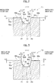
Fig. 2 ] It is a cross-sectional view taken along a line II-II shown inFig. 1 . - [
Fig. 3 ] It is a cross-sectional view of a circumferential main groove according to a comparative sample. - [
Fig. 4 ] It is a cross-sectional view of a circumferential main groove of a pneumatic tire according to a prior art. - Hereinafter, an embodiment will be described with reference to the drawings. Configurational elements identical or equivalent to each other are labeled with identical signs. Note that the drawings show configurational elements schematically, and it should be understood that the configurational elements shown in the drawings don't indicate their actuals. Further, actual dimensions of the configurational elements and actual proportions between the configurational elements may be shown differently in the drawings.
- Dimensions, angles and so on are measured in a state where the tire is mounted onto an applied rim, a regulated inner pressure is applied thereto, and no load is applied thereto. The "regulated inner pressure" denotes an air pressure regulated according to a maximum load rating in a Standard. The "applied rim" denotes a rim regulated according to a tire size in the Standard. In Japan, the above-mentioned Standard denotes "JATMA YEAR BOOK (here, 2008 edition)" issued by the Japan Automobile Tyre Manufacturers Association. Note that, in a case where the TRA Standard, the ETRTO Standard or the like is applied in a region where it is used or manufactured, the above-mentioned Standard should comply with each of the Standards.
- As shown in
Fig. 1 , atread 10 of the pneumatic tire T1 according to the present embodiment includes plural circumferentialmain grooves 50A extending in a tire circumferential direction, andplural land portions main grooves 50A. The "land portions" include blocks and ribs on thetread 10. - In the pneumatic tire T1, the three land portions (ribs) 11 is formed, by the three circumferential
main grooves 50A, at a central region of thetread 10. In addition, a pair of theland portions 12 is formed at both side regions of thetread 10. A tread pattern is formed by theseland portions 11 and 12 (and small grooves formed on theland portions 11 and 12) and the circumferentialmain grooves 50A. - As shown in
Fig. 2 (a cross-sectional view along a width direction), in the pneumatic tire T1, theland portion 11 is formed so as to be interposed between the circumferentialmain grooves 50A, and the circumferentialmain groove 50A has agroove bottom surface 51, groove wall surfaces 52 (52a and 52b), and curved portions (groove bottom corners) 53 (53a and 53b) connecting thegroove bottom surface 51 with the groove wall surfaces 52. In the present embodiment, thegroove bottom surface 51 and the groove wall surfaces 52 are formed flat, but not limited to be flat. Thegroove bottom surface 51 and the groove wall surfaces 52 may be formed to be curved with a curvature radius larger than a curvature radius of the curved portions 53. - The curved portions 53 includes an outside
curved portion 53a on an installation outer side and an insidecurved portion 53b on an installation inner side. In a cross-sectional groove view (the cross-sectional view along the width direction), (a minimum curvature radius R1 of the outsidecurved portion 53a) > (a minimum curvature radius R2 of the insidecurved portion 53b) is satisfied. The reason why the "minimum" curvature radius is used here is that the curved portion 53 (53a or 53b) may be formed with a uniform curvature radius, or may be formed so that its curvature radius varies continuously. In the present embodiment, each of the curved portions 53 (53a or 53b) is formed with a uniform curvature radius so as to connect the flatgroove bottom surface 51 continuously with the flat groove wall surface 52 (52a or 52b). - Further, in the cross-sectional groove view (the cross-sectional view along the width direction), with respect to angles (groove wall angles) of the groove wall surfaces 52 to a tread normal line (s) N at border edges between the groove wall surfaces 52 and a tread surface 60, an inequality (the groove wall angle α on the installation outer side) < (the groove wall angle β on the installation inner side) is satisfied. Note that, with respect to the installation outer side, the angle of the outside
groove wall surface 52a to the tread normal line N at the border edge between the outsidegroove wall surface 52a and thetread surface 60a is the groove wall angle α (≥0). Similarly, with respect to the installation inner side, the angle of the insidegroove wall surface 52b to the tread normal line N at the border edge between the insidegroove wall surface 52b and thetread surface 60b is the groove wall angle β (≥0). - In addition, it is preferable that the minimum curvature radius R1 of the outside
curved portion 53a is not more than twice the minimum curvature radius R2 of the insidecurved portion 53b. Further, it is preferable that the groove wall angles on the installation inner side is in a range from (the groove wall angle α on the installation outer side + 2°) to (α+30°) [i.e. (a+2°)≤β≤(α+30°)], and it is more preferable that it is in a range from (α + 2°) to (α + 10°) [i.e. (α+2°)≤β≤(α+10°)]. For example, in a case of α=10°, β=12°∼40° is preferable. Note thatFig. 2 shows a case where α=10° and β=12°. - In addition, in the present embodiment as shown in
Fig. 2 , beveled portions 61 are formed between the groove wall surfaces 52 and the tread surface 60. Note that, with respect to the installation outer side, the outsidebeveled portion 61a is formed between the outsidegroove wall surface 52a and thetread surface 60a, and, with respect to the installation inner side, the inside beveledportion 61b is formed between the insidegroove wall surface 52b and thetread surface 60b. Namely, thetread surface 60a has the outside beveledportion 61a adjacently to the outsidegroove wall surface 52a on the installation outer side, and thetread surface 60b has the inside beveledportion 61b adjacently to the insidegroove wall surface 52b on the installation inner side. - In the cross-sectional groove view (the cross-sectional view along the width direction), when a distance along a tire radial direction from an uppermost portion of the
land portion 11 to the border edge between the outsidebeveled portion 61a and the outsidegroove wall surface 52a is denoted as H1 and a distance along a tire radial direction from an uppermost portion of theland portion 11 to the border edge between the inside beveledportion 61b and the insidegroove wall surface 52b is denoted as H2, an inequality H1>H2 is satisfied. The reason why this configuration is adopted is to untangle a concern that a ground contact pressure on a side where the above-mentioned (minimum) curvature radius is larger (a ground contact pressure of theland portion 11 on the installation outer side in this case) becomes high. - The above-mentioned configurations with respect to the cross-sectional groove view (the cross-sectional view along the width direction) may be applied to all of the circumferential
main grooves 50A, or may be applied only to the circumferentialmain grooves 50A in the central region that are close to a tire equator line. In consideration to cornering performance, they can be applied only to the circumferentialmain grooves 50A on the installation outer side from the tire equator line. In the present embodiment, the above-mentioned configurations are applied to all of the circumferentialmain grooves 50A. In the present embodiment, as shown inFig. 1 , the four circumferentialmain grooves 50A are formed in total, the two circumferentialmain grooves 50A in the central region and the two circumferentialmain grooves 50A on outer sides thereof. Here, in a case of a tire whose installation side to a vehicle is designated, stiffness of theland portions - According to the pneumatic tire T1 in the embodiment, an effect for supporting an installation inner side portion of the
land portion 11 located on the installation inner side from the circumferentialmain groove 50A improves, and thereby theland portion 11 can resist effectively against a lateral input force from the installation outer side during cornering (the pneumatic tire T1 locates on a cornering outer side). As the result, an inclining deformation of the land portion (s) 11 can be restricted to improve handling stability. - In addition, if the curvature radii of the curved portions 53 are enlarged, the curved portions 53 intrude into the inside of the circumferential
main groove 50A in proportion to their enlarged amounts. Therefore, a cross-sectional area of the circumferentialmain groove 50A decreases, so that water drainage performance may be degraded. However, in the present embodiment, only the minimum curvature radius R1 of the outsidecurved portion 53a is relatively enlarged, so that water drainage performance can be prevented from degrading and handling stability can be improved. - In addition, if the curved portions 53 are made asymmetric, strain concentrates to the smaller curvature side and cracks may occur. However, (the groove wall angle α on the installation outer side) < (the groove wall angle β on the installation inner side) is satisfied in the present embodiment, local concentration of stain can be prevented. Specifically, since the groove wall angle β with the smaller curvature on the installation inner side is made larger (than the groove wall angle α with the larger curvature on the installation outer side), concentration of stain to the
curved portion 53b with the smaller curvature on the installation inner side can be avoided while a lateral input force is applied from the outer side (in a case where the tire T1 is a cornering outer-side wheel), and thereby an inclining deformation of theland portion 11 adjacent to thecurved portion 53b can be restricted to improve handling stability. In addition, since the concentration of stain to thecurved portion 53b can be avoided, occurrence of cracks can be also restricted. - Further, due to balancing of the groove wall angles α and β, the minimum curvature radii R1 and R2 of the curved portions 53 (53a and 53b), and the distances H1 and H2 along the tire radial direction from the uppermost portion of the
land portion 11 to the border edges between the beveled portions 61 (61a and 61b) and the groove wall surfaces 52 (52a and 52b) that are mentioned above, a stiffness balance along the tire width direction of the groove wall surfaces 52 (52a and 52b) (i.e. theland portions 11 on the installation outer and inner sides) with respect to the center of the circumferentialmain groove 50A can be equalized, so that water drainage performance and anti-crack performance can be improved in this point. Specifically, (the groove wall angle α on the installation outer side) < (the groove wall angle β on the installation inner side) is satisfied with respect to the groove wall angles α and β, but (the distance H1 on the installation outer side) > (the distance H2 on the installation inner side) is satisfied with respect to the distances H1 and H2, namely their inequality signs are reversal. As the result, a stiffness balance along the tire width direction between theland portion 11 on the installation outer side and theland portion 11 on the installation inner side can be equalized. - In addition, if the minimum curvature radius R1 of the outside
curved portion 53a is more than twice the minimum curvature radius R2 of the insidecurved portion 53b, the stiffness balance along the tire width direction between the groove wall surfaces 52 (52a and 52b) degrades and thereby uneven wear or degradation of handling stability may occur. However, since the minimum curvature radius R1 of the outsidecurved portion 53a is not more than twice the minimum curvature radius R2 of the insidecurved portion 53b, uneven wear or degradation of handling stability doesn't occur. - In addition, it becomes hard to balance handling stability and water drainage performance optimally when the groove wall angle β on the installation inner side is less than (the groove wall angle α on the installation outer side + 2°), and the stiffness balance along the tire width direction between the groove wall surfaces 52 (52a and 52b) may degrade when it gets more than (α + 30°). Since the groove wall angle β on the installation inner side is in a range from (the groove wall angle α on the installation outer side + 2°) to (α + 30°) in the present embodiment, handling stability and water drainage performance can be kept at a high level. Especially, if the groove wall angle β on the installation inner side is in a range from (the groove wall angle α on the installation outer side + 2°) to ( + 10°), the stiffness balance along the tire width direction between the groove wall surfaces 52 (52a and 52b) can be surely restricted from degrading.
- In addition, if stiffness of the groove wall surfaces 52 (52a and 52b) is strengthened, a ground contact pressure at side edges of the
land portion 11 becomes large and thereby it is concerned that local wear occurs. However, since the beveled portions 61 are formed between the groove wall surfaces 52 and the tread surface 60 in the present embodiment, it is possible to restrict the wear by reducing the ground contact pressure at side edges of the beveled portions 61 (the side edges of theland portion 11, side edges of the tread surface 60). - Note that it is preferable that the minimum curvature radius R1 of the outside
curved portion 53a is 3mm to 12mm. If R1 is less than 3mm, handling stability may degrade due to degradation of the stiffness of the groove wall surfaces 52 against a lateral input force, and, if it is more than 12mm, water drainage performance may degrade due to reduction of the cross-sectional area of the circumferentialmain groove 50A. - On the other hand, it is preferable that the minimum curvature radius R2 of the inside
curved portion 53b is 2mm to 6mm. If R2 is less than 2mm, anti-crack performance may degrade due to concentration of strain, and, if it is more than 6mm, water drainage performance may degrade due to reduction of the cross-sectional area of the circumferentialmain groove 50A. - In addition, it is preferable that the groove wall angles α and β in a range from 0 to 30°.
- A circumferential
main groove 50B of a pneumatic tire T2 according to a comparative sample will be described with reference toFig. 3 . Note that identical configurations to those in the above embodiment will be labeled with identical signs and their redundant descriptions will be omitted. - In the circumferential
main groove 50A of the pneumatic tire T1 according to the above embodiment, (the groove wall angle α on the installation outer side) < (the groove wall angle β on the installation inner side) is satisfied. On the other hand, in the circumferentialmain groove 50B of the pneumatic tire T2 according to the present comparative sample, (the groove wall angle α on the installation outer side) = (the groove wall angle β on the installation inner side) is satisfied. Note thatFig. 3 shows a case where α=β=10°. - Characteristics of the pneumatic tires according to the prior art, the comparative sample, and the embodiment (
samples 1 to 3) that are mentioned above will be shown in a [Table 1] shown below. Comparative tests were done by using the prior art, the comparative sample, and the embodiment (samples 1 to 3) . Although the tests will be explained later, the [Table 1] also shows results of the tests. - Note that F1/F2 in the [Table 1] will be explained. As shown in
Fig. 2 to Fig. 4 , F1 is a cross-sectional area of an area enclosed by the outside curbedportion 53a (101), an extended line of the groove bottom surface 51 (107), and an extended line of the outsidegroove wall surface 52a in the cross-sectional groove view (the cross-sectional view along the width direction). Similarly, F2 is a cross-sectional area of an area enclosed by the inside curbedportion 53b (102), another extended line of the groove bottom surface 51 (107), and an extended line of the insidegroove wall surface 52b in the cross-sectional groove view (the cross-sectional view along the width direction). F1/F2 is an area ratio of these F1 and F2. Note that, if the area ratio F1/F2 is less than 0.5, handling stability doesn't improve against a lateral input force from the outer side, and, if it is more than 8, water drainage performance degrades due to inhibition of flowability in the circumferentialmain groove 50A (50B, 100). In addition, if the area ratio F1/F2 is more than 8, difference of strain between the outsidecurved portion 53a (101) and the insidecurved portion 53b (102) becomes large, and thereby cracks easily occur. Therefore, it is preferable that the area ratio is 1.5 to 8.0, and, especially, it is more preferable that it is 1.5 to 3.0. If the area ratio F1/F2 is not more than 3.0, it is possible to balance handling stability, water drainage performance and anti-crack performance at a high level.[Table 1] Prior Art Comparative Sample Embodiment Sample 1 Sample 2 Sample 3 Fig. Fig. 4 Fig. 3 Fig. 2 R1 (mm) 3.0 4.0 5.0 R2 (mm) 2.0 α, β α>β α=β α<β F1/F2 1.5 - 8.0 Cracks on Groove Bottom Occur Not Occur Ride Comfort 100 101 105 103 Handling Stability (Dry/Wet Road) 100 101 106 104 - In the tests, a tire having a size 195/65R15 is mounted on a rim having a size 6J. Note that a load is 4kN, and a tire inner pressure is 210kPa (evaluations for ride comfort and handling stability). In addition, by using a drum test machine with a 7m diameter, it is run 30,000 km at 60km/h by rotating its drum in a state where a load 3.78N is applied (evaluation for cracks on groove bottom). Note that handling stability at the lowermost row in the [Table 1] is shown as a relative evaluation under a condition where the prior art is evaluated as 100, and handling stability becomes better as its value gets higher.
- As being obvious from the [table 1], in the pneumatic tire(s) T1 according to the
embodiment samples 1 to 3, no crack occurs on the bottoms of the circumferentialmain grooves 50A. On the other hand, in the pneumatic tire T10 according to the prior art and the pneumatic tire T2 according to the comparative sample, cracks occur on the bottoms of the circumferentialmain grooves embodiment samples 1 and 2 gets a good evaluation "105" with respect to ride comfort. In addition, the pneumatic tire(s) T1 according to theembodiment samples 1 and 2 also gets a good evaluation "106" with respect to handling stability on dry and wet roads. - Hereinbefore, although the present invention is described in detail by using the above embodiment, it is obvious for a parson ordinarily skilled in the art that the present invention is not limited to the embodiment described in this Description. The present invention can be carried out as modified and changed embodiments without departing from the sprit and scope of the present invention determined by Claims. Therefore, descriptions in this Description intend to be exemplary explanations, and don't intend to add any limiting meanings to the present invention.
- All contents of
Japanese Patent Application No. 2014-104046 (filed on May 20, 2014
Claims (5)
- A pneumatic tire comprising:a tread that has a tread surface;a plurality of circumferential main grooves that are formed on the tread; anda plurality of land portions that are formed, on the tread, between the plurality of circumferential main grooves, whereineach of the plurality of circumferential main grooves has, in a lateral cross-sectional view, a groove bottom surface, an outside groove wall surface located on an installation outer side, an inside groove wall surface located on an installation inner side, an outside curved portion connecting the groove bottom surface with the outside groove wall surface, and an inside curved portion connecting the groove bottom surface with the inside groove wall surface,(a minimum curvature radius of the outside curved portion) > (a minimum curvature radius of the inside curved portion) is satisfied in the lateral cross-sectional view, and,when, in the lateral cross-sectional view, an angle of the outside groove wall surface to a tread normal line at a border edge between the outside groove wall surface and the tread surface is denoted as a groove wall angle α and an angle of the outside groove wall surface to a tread normal line at a border edge between the inside groove wall surface and the tread surface is denoted as a groove wall angle β, (the groove wall angle α) < (the groove wall angle β) is satisfied.
- The pneumatic tire according to claim 1, wherein
the minimum curvature radius of the outside curved portion is not more than twice the minimum curvature radius of the inside curved portion. - The pneumatic tire according to claim 1 or 2, wherein
the groove wall angle β is in a range from (the groove wall angle α + 2°) to (the groove wall angle α + 30°). - The pneumatic tire according to any one of claims 1 to 3, wherein
the tread surface has beveled portions adjacent to the outside groove wall surface and the inside groove wall surface. - The pneumatic tire according to claim 4, wherein
the beveled portions includes an outside beveled portion adjacent to the outside groove wall surface and an inside beveled portion adjacent to the inside groove wall surface, and,
when a distance along a tire radial direction from an uppermost portion of the land portion on which the outside beveled portion is formed to the border edge between the outside beveled portion and the outside groove wall surface is denoted as H1 and a distance along a tire radial direction from an uppermost portion of the land portion on which the inside beveled portion is formed to the border edge between the inside beveled portion and the inside groove wall surface is denoted as H2, H1>H2 is satisfied.
Applications Claiming Priority (2)
| Application Number | Priority Date | Filing Date | Title |
|---|---|---|---|
| JP2014104046A JP6282930B2 (en) | 2014-05-20 | 2014-05-20 | Pneumatic tire |
| PCT/JP2015/062218 WO2015178152A1 (en) | 2014-05-20 | 2015-04-22 | Pneumatic tire |
Publications (3)
| Publication Number | Publication Date |
|---|---|
| EP3147140A1 true EP3147140A1 (en) | 2017-03-29 |
| EP3147140A4 EP3147140A4 (en) | 2017-06-07 |
| EP3147140B1 EP3147140B1 (en) | 2018-10-17 |
Family
ID=54553828
Family Applications (1)
| Application Number | Title | Priority Date | Filing Date |
|---|---|---|---|
| EP15795565.9A Not-in-force EP3147140B1 (en) | 2014-05-20 | 2015-04-22 | Pneumatic tire |
Country Status (5)
| Country | Link |
|---|---|
| US (1) | US10639939B2 (en) |
| EP (1) | EP3147140B1 (en) |
| JP (1) | JP6282930B2 (en) |
| CN (1) | CN106457925B (en) |
| WO (1) | WO2015178152A1 (en) |
Families Citing this family (5)
| Publication number | Priority date | Publication date | Assignee | Title |
|---|---|---|---|---|
| WO2016076242A1 (en) * | 2014-11-12 | 2016-05-19 | 横浜ゴム株式会社 | Pneumatic tire and vehicle |
| USD811312S1 (en) * | 2015-02-27 | 2018-02-27 | The Yokohama Rubber Co., Ltd. | Automobile tire |
| JP6955427B2 (en) * | 2017-11-17 | 2021-10-27 | Toyo Tire株式会社 | Pneumatic tires |
| JP7118625B2 (en) * | 2017-11-17 | 2022-08-16 | Toyo Tire株式会社 | pneumatic tire |
| CN111619291B (en) * | 2020-04-28 | 2021-07-27 | 中策橡胶集团有限公司 | Design method of durable groove bottom pattern of heavy-duty tire and tire thereof |
Family Cites Families (16)
| Publication number | Priority date | Publication date | Assignee | Title |
|---|---|---|---|---|
| JP2536852B2 (en) * | 1986-09-10 | 1996-09-25 | 株式会社ブリヂストン | Pneumatic radial tires for heavy loads |
| JPH0342306A (en) | 1989-07-11 | 1991-02-22 | Bridgestone Corp | Pneumatic tire |
| US5407005A (en) * | 1994-04-04 | 1995-04-18 | The Goodyear Tire & Rubber Company | Tread for a tire |
| JP4468545B2 (en) * | 2000-04-06 | 2010-05-26 | 株式会社ブリヂストン | Pneumatic tire |
| JP2002029219A (en) * | 2000-07-19 | 2002-01-29 | Bridgestone Corp | Pneumatic tire and mounting method for it |
| WO2003033280A1 (en) | 2001-10-11 | 2003-04-24 | Sumitomo Rubber Industries, Ltd. | Pneumatic tire |
| JP3809173B2 (en) * | 2004-07-16 | 2006-08-16 | 横浜ゴム株式会社 | Pneumatic tire |
| DE102005042903A1 (en) | 2005-09-08 | 2007-03-22 | Continental Aktiengesellschaft | Tread pattern of a vehicle tire |
| US8794279B2 (en) | 2007-03-13 | 2014-08-05 | Bridgestone Corporation | Pneumatic tire with tread including thin groove having rounded corner portions |
| JP5262204B2 (en) * | 2008-03-11 | 2013-08-14 | 横浜ゴム株式会社 | Pneumatic tire |
| CN102216092A (en) * | 2008-10-08 | 2011-10-12 | 株式会社普利司通 | Tire |
| JP5174102B2 (en) * | 2010-08-23 | 2013-04-03 | 住友ゴム工業株式会社 | Pneumatic tire |
| JP5626383B2 (en) | 2012-03-21 | 2014-11-19 | 横浜ゴム株式会社 | Pneumatic tire |
| JP5482938B1 (en) | 2013-05-14 | 2014-05-07 | 横浜ゴム株式会社 | Pneumatic tire |
| JP5842938B2 (en) * | 2014-01-06 | 2016-01-13 | 株式会社三洋物産 | Game machine |
| US10592580B2 (en) * | 2014-04-25 | 2020-03-17 | Ebay Inc. | Web UI builder application |
-
2014
- 2014-05-20 JP JP2014104046A patent/JP6282930B2/en not_active Expired - Fee Related
-
2015
- 2015-04-22 US US15/312,152 patent/US10639939B2/en active Active
- 2015-04-22 CN CN201580026657.8A patent/CN106457925B/en not_active Expired - Fee Related
- 2015-04-22 EP EP15795565.9A patent/EP3147140B1/en not_active Not-in-force
- 2015-04-22 WO PCT/JP2015/062218 patent/WO2015178152A1/en not_active Ceased
Also Published As
| Publication number | Publication date |
|---|---|
| US20170100966A1 (en) | 2017-04-13 |
| WO2015178152A1 (en) | 2015-11-26 |
| JP2015217864A (en) | 2015-12-07 |
| EP3147140A4 (en) | 2017-06-07 |
| EP3147140B1 (en) | 2018-10-17 |
| CN106457925B (en) | 2018-11-30 |
| US10639939B2 (en) | 2020-05-05 |
| JP6282930B2 (en) | 2018-02-21 |
| CN106457925A (en) | 2017-02-22 |
Similar Documents
| Publication | Publication Date | Title |
|---|---|---|
| EP2899041B1 (en) | Pneumatic tire | |
| EP2732983B1 (en) | Pneumatic tire | |
| US20100269967A1 (en) | Heavy duty radial tire | |
| EP3147140B1 (en) | Pneumatic tire | |
| EP3332991B1 (en) | Pneumatic tire | |
| US10787036B2 (en) | Heavy-duty tire | |
| US20210197622A1 (en) | Tyre | |
| US11654720B2 (en) | Tire | |
| CN109130707B (en) | Tyre for vehicle wheels | |
| US11904639B2 (en) | Tire | |
| EP3990295B1 (en) | A noise improving tread | |
| US11446964B2 (en) | Tyre | |
| EP2826642B1 (en) | Pneumatic radial tire | |
| US20200130416A1 (en) | Pneumatic tire | |
| CN114867618B (en) | Improved noise tread | |
| JP2007076594A (en) | Pneumatic tire | |
| US12187079B2 (en) | Motorcycle tire | |
| JP4639776B2 (en) | Heavy duty pneumatic radial tire | |
| EP4098460A1 (en) | Pneumatic tire for heavy duty | |
| WO2022137414A1 (en) | A tire for improved noise performance | |
| US20090223616A1 (en) | Pneumatic tire |
Legal Events
| Date | Code | Title | Description |
|---|---|---|---|
| STAA | Information on the status of an ep patent application or granted ep patent |
Free format text: STATUS: THE INTERNATIONAL PUBLICATION HAS BEEN MADE |
|
| PUAI | Public reference made under article 153(3) epc to a published international application that has entered the european phase |
Free format text: ORIGINAL CODE: 0009012 |
|
| STAA | Information on the status of an ep patent application or granted ep patent |
Free format text: STATUS: REQUEST FOR EXAMINATION WAS MADE |
|
| 17P | Request for examination filed |
Effective date: 20161128 |
|
| AK | Designated contracting states |
Kind code of ref document: A1 Designated state(s): AL AT BE BG CH CY CZ DE DK EE ES FI FR GB GR HR HU IE IS IT LI LT LU LV MC MK MT NL NO PL PT RO RS SE SI SK SM TR |
|
| AX | Request for extension of the european patent |
Extension state: BA ME |
|
| A4 | Supplementary search report drawn up and despatched |
Effective date: 20170508 |
|
| RIC1 | Information provided on ipc code assigned before grant |
Ipc: B60C 11/03 20060101ALI20170428BHEP Ipc: B60C 11/13 20060101AFI20170428BHEP |
|
| DAV | Request for validation of the european patent (deleted) | ||
| DAX | Request for extension of the european patent (deleted) | ||
| GRAP | Despatch of communication of intention to grant a patent |
Free format text: ORIGINAL CODE: EPIDOSNIGR1 |
|
| STAA | Information on the status of an ep patent application or granted ep patent |
Free format text: STATUS: GRANT OF PATENT IS INTENDED |
|
| INTG | Intention to grant announced |
Effective date: 20180507 |
|
| GRAS | Grant fee paid |
Free format text: ORIGINAL CODE: EPIDOSNIGR3 |
|
| GRAA | (expected) grant |
Free format text: ORIGINAL CODE: 0009210 |
|
| STAA | Information on the status of an ep patent application or granted ep patent |
Free format text: STATUS: THE PATENT HAS BEEN GRANTED |
|
| AK | Designated contracting states |
Kind code of ref document: B1 Designated state(s): AL AT BE BG CH CY CZ DE DK EE ES FI FR GB GR HR HU IE IS IT LI LT LU LV MC MK MT NL NO PL PT RO RS SE SI SK SM TR |
|
| REG | Reference to a national code |
Ref country code: GB Ref legal event code: FG4D |
|
| REG | Reference to a national code |
Ref country code: CH Ref legal event code: EP |
|
| REG | Reference to a national code |
Ref country code: IE Ref legal event code: FG4D |
|
| REG | Reference to a national code |
Ref country code: DE Ref legal event code: R096 Ref document number: 602015018433 Country of ref document: DE Ref country code: AT Ref legal event code: REF Ref document number: 1053549 Country of ref document: AT Kind code of ref document: T Effective date: 20181115 |
|
| REG | Reference to a national code |
Ref country code: NL Ref legal event code: MP Effective date: 20181017 |
|
| REG | Reference to a national code |
Ref country code: LT Ref legal event code: MG4D |
|
| REG | Reference to a national code |
Ref country code: AT Ref legal event code: MK05 Ref document number: 1053549 Country of ref document: AT Kind code of ref document: T Effective date: 20181017 |
|
| PG25 | Lapsed in a contracting state [announced via postgrant information from national office to epo] |
Ref country code: NL Free format text: LAPSE BECAUSE OF FAILURE TO SUBMIT A TRANSLATION OF THE DESCRIPTION OR TO PAY THE FEE WITHIN THE PRESCRIBED TIME-LIMIT Effective date: 20181017 |
|
| PG25 | Lapsed in a contracting state [announced via postgrant information from national office to epo] |
Ref country code: ES Free format text: LAPSE BECAUSE OF FAILURE TO SUBMIT A TRANSLATION OF THE DESCRIPTION OR TO PAY THE FEE WITHIN THE PRESCRIBED TIME-LIMIT Effective date: 20181017 Ref country code: NO Free format text: LAPSE BECAUSE OF FAILURE TO SUBMIT A TRANSLATION OF THE DESCRIPTION OR TO PAY THE FEE WITHIN THE PRESCRIBED TIME-LIMIT Effective date: 20190117 Ref country code: IS Free format text: LAPSE BECAUSE OF FAILURE TO SUBMIT A TRANSLATION OF THE DESCRIPTION OR TO PAY THE FEE WITHIN THE PRESCRIBED TIME-LIMIT Effective date: 20190217 Ref country code: AT Free format text: LAPSE BECAUSE OF FAILURE TO SUBMIT A TRANSLATION OF THE DESCRIPTION OR TO PAY THE FEE WITHIN THE PRESCRIBED TIME-LIMIT Effective date: 20181017 Ref country code: HR Free format text: LAPSE BECAUSE OF FAILURE TO SUBMIT A TRANSLATION OF THE DESCRIPTION OR TO PAY THE FEE WITHIN THE PRESCRIBED TIME-LIMIT Effective date: 20181017 Ref country code: PL Free format text: LAPSE BECAUSE OF FAILURE TO SUBMIT A TRANSLATION OF THE DESCRIPTION OR TO PAY THE FEE WITHIN THE PRESCRIBED TIME-LIMIT Effective date: 20181017 Ref country code: LT Free format text: LAPSE BECAUSE OF FAILURE TO SUBMIT A TRANSLATION OF THE DESCRIPTION OR TO PAY THE FEE WITHIN THE PRESCRIBED TIME-LIMIT Effective date: 20181017 Ref country code: BG Free format text: LAPSE BECAUSE OF FAILURE TO SUBMIT A TRANSLATION OF THE DESCRIPTION OR TO PAY THE FEE WITHIN THE PRESCRIBED TIME-LIMIT Effective date: 20190117 Ref country code: FI Free format text: LAPSE BECAUSE OF FAILURE TO SUBMIT A TRANSLATION OF THE DESCRIPTION OR TO PAY THE FEE WITHIN THE PRESCRIBED TIME-LIMIT Effective date: 20181017 Ref country code: LV Free format text: LAPSE BECAUSE OF FAILURE TO SUBMIT A TRANSLATION OF THE DESCRIPTION OR TO PAY THE FEE WITHIN THE PRESCRIBED TIME-LIMIT Effective date: 20181017 |
|
| PG25 | Lapsed in a contracting state [announced via postgrant information from national office to epo] |
Ref country code: AL Free format text: LAPSE BECAUSE OF FAILURE TO SUBMIT A TRANSLATION OF THE DESCRIPTION OR TO PAY THE FEE WITHIN THE PRESCRIBED TIME-LIMIT Effective date: 20181017 Ref country code: SE Free format text: LAPSE BECAUSE OF FAILURE TO SUBMIT A TRANSLATION OF THE DESCRIPTION OR TO PAY THE FEE WITHIN THE PRESCRIBED TIME-LIMIT Effective date: 20181017 Ref country code: RS Free format text: LAPSE BECAUSE OF FAILURE TO SUBMIT A TRANSLATION OF THE DESCRIPTION OR TO PAY THE FEE WITHIN THE PRESCRIBED TIME-LIMIT Effective date: 20181017 Ref country code: PT Free format text: LAPSE BECAUSE OF FAILURE TO SUBMIT A TRANSLATION OF THE DESCRIPTION OR TO PAY THE FEE WITHIN THE PRESCRIBED TIME-LIMIT Effective date: 20190217 Ref country code: GR Free format text: LAPSE BECAUSE OF FAILURE TO SUBMIT A TRANSLATION OF THE DESCRIPTION OR TO PAY THE FEE WITHIN THE PRESCRIBED TIME-LIMIT Effective date: 20190118 |
|
| REG | Reference to a national code |
Ref country code: DE Ref legal event code: R097 Ref document number: 602015018433 Country of ref document: DE |
|
| PG25 | Lapsed in a contracting state [announced via postgrant information from national office to epo] |
Ref country code: CZ Free format text: LAPSE BECAUSE OF FAILURE TO SUBMIT A TRANSLATION OF THE DESCRIPTION OR TO PAY THE FEE WITHIN THE PRESCRIBED TIME-LIMIT Effective date: 20181017 Ref country code: DK Free format text: LAPSE BECAUSE OF FAILURE TO SUBMIT A TRANSLATION OF THE DESCRIPTION OR TO PAY THE FEE WITHIN THE PRESCRIBED TIME-LIMIT Effective date: 20181017 |
|
| PLBE | No opposition filed within time limit |
Free format text: ORIGINAL CODE: 0009261 |
|
| STAA | Information on the status of an ep patent application or granted ep patent |
Free format text: STATUS: NO OPPOSITION FILED WITHIN TIME LIMIT |
|
| PG25 | Lapsed in a contracting state [announced via postgrant information from national office to epo] |
Ref country code: EE Free format text: LAPSE BECAUSE OF FAILURE TO SUBMIT A TRANSLATION OF THE DESCRIPTION OR TO PAY THE FEE WITHIN THE PRESCRIBED TIME-LIMIT Effective date: 20181017 Ref country code: SM Free format text: LAPSE BECAUSE OF FAILURE TO SUBMIT A TRANSLATION OF THE DESCRIPTION OR TO PAY THE FEE WITHIN THE PRESCRIBED TIME-LIMIT Effective date: 20181017 Ref country code: RO Free format text: LAPSE BECAUSE OF FAILURE TO SUBMIT A TRANSLATION OF THE DESCRIPTION OR TO PAY THE FEE WITHIN THE PRESCRIBED TIME-LIMIT Effective date: 20181017 Ref country code: SK Free format text: LAPSE BECAUSE OF FAILURE TO SUBMIT A TRANSLATION OF THE DESCRIPTION OR TO PAY THE FEE WITHIN THE PRESCRIBED TIME-LIMIT Effective date: 20181017 |
|
| 26N | No opposition filed |
Effective date: 20190718 |
|
| PG25 | Lapsed in a contracting state [announced via postgrant information from national office to epo] |
Ref country code: SI Free format text: LAPSE BECAUSE OF FAILURE TO SUBMIT A TRANSLATION OF THE DESCRIPTION OR TO PAY THE FEE WITHIN THE PRESCRIBED TIME-LIMIT Effective date: 20181017 |
|
| REG | Reference to a national code |
Ref country code: CH Ref legal event code: PL |
|
| REG | Reference to a national code |
Ref country code: BE Ref legal event code: MM Effective date: 20190430 |
|
| GBPC | Gb: european patent ceased through non-payment of renewal fee |
Effective date: 20190422 |
|
| PG25 | Lapsed in a contracting state [announced via postgrant information from national office to epo] |
Ref country code: LU Free format text: LAPSE BECAUSE OF NON-PAYMENT OF DUE FEES Effective date: 20190422 Ref country code: MC Free format text: LAPSE BECAUSE OF FAILURE TO SUBMIT A TRANSLATION OF THE DESCRIPTION OR TO PAY THE FEE WITHIN THE PRESCRIBED TIME-LIMIT Effective date: 20181017 |
|
| PG25 | Lapsed in a contracting state [announced via postgrant information from national office to epo] |
Ref country code: LI Free format text: LAPSE BECAUSE OF NON-PAYMENT OF DUE FEES Effective date: 20190430 Ref country code: GB Free format text: LAPSE BECAUSE OF NON-PAYMENT OF DUE FEES Effective date: 20190422 Ref country code: CH Free format text: LAPSE BECAUSE OF NON-PAYMENT OF DUE FEES Effective date: 20190430 |
|
| PG25 | Lapsed in a contracting state [announced via postgrant information from national office to epo] |
Ref country code: BE Free format text: LAPSE BECAUSE OF NON-PAYMENT OF DUE FEES Effective date: 20190430 |
|
| PG25 | Lapsed in a contracting state [announced via postgrant information from national office to epo] |
Ref country code: TR Free format text: LAPSE BECAUSE OF FAILURE TO SUBMIT A TRANSLATION OF THE DESCRIPTION OR TO PAY THE FEE WITHIN THE PRESCRIBED TIME-LIMIT Effective date: 20181017 |
|
| PG25 | Lapsed in a contracting state [announced via postgrant information from national office to epo] |
Ref country code: IE Free format text: LAPSE BECAUSE OF NON-PAYMENT OF DUE FEES Effective date: 20190422 |
|
| PG25 | Lapsed in a contracting state [announced via postgrant information from national office to epo] |
Ref country code: CY Free format text: LAPSE BECAUSE OF FAILURE TO SUBMIT A TRANSLATION OF THE DESCRIPTION OR TO PAY THE FEE WITHIN THE PRESCRIBED TIME-LIMIT Effective date: 20181017 |
|
| PG25 | Lapsed in a contracting state [announced via postgrant information from national office to epo] |
Ref country code: HU Free format text: LAPSE BECAUSE OF FAILURE TO SUBMIT A TRANSLATION OF THE DESCRIPTION OR TO PAY THE FEE WITHIN THE PRESCRIBED TIME-LIMIT; INVALID AB INITIO Effective date: 20150422 Ref country code: MT Free format text: LAPSE BECAUSE OF FAILURE TO SUBMIT A TRANSLATION OF THE DESCRIPTION OR TO PAY THE FEE WITHIN THE PRESCRIBED TIME-LIMIT Effective date: 20181017 |
|
| PG25 | Lapsed in a contracting state [announced via postgrant information from national office to epo] |
Ref country code: MK Free format text: LAPSE BECAUSE OF FAILURE TO SUBMIT A TRANSLATION OF THE DESCRIPTION OR TO PAY THE FEE WITHIN THE PRESCRIBED TIME-LIMIT Effective date: 20181017 |
|
| PGFP | Annual fee paid to national office [announced via postgrant information from national office to epo] |
Ref country code: IT Payment date: 20220420 Year of fee payment: 8 Ref country code: FR Payment date: 20220421 Year of fee payment: 8 Ref country code: DE Payment date: 20220420 Year of fee payment: 8 |
|
| P01 | Opt-out of the competence of the unified patent court (upc) registered |
Effective date: 20230531 |
|
| REG | Reference to a national code |
Ref country code: DE Ref legal event code: R119 Ref document number: 602015018433 Country of ref document: DE |
|
| PG25 | Lapsed in a contracting state [announced via postgrant information from national office to epo] |
Ref country code: FR Free format text: LAPSE BECAUSE OF NON-PAYMENT OF DUE FEES Effective date: 20230430 Ref country code: DE Free format text: LAPSE BECAUSE OF NON-PAYMENT OF DUE FEES Effective date: 20231103 |
|
| PG25 | Lapsed in a contracting state [announced via postgrant information from national office to epo] |
Ref country code: IT Free format text: LAPSE BECAUSE OF NON-PAYMENT OF DUE FEES Effective date: 20230422 |