EP3147137A1 - Non-pneumatic tire - Google Patents
Non-pneumatic tire Download PDFInfo
- Publication number
- EP3147137A1 EP3147137A1 EP15796467.7A EP15796467A EP3147137A1 EP 3147137 A1 EP3147137 A1 EP 3147137A1 EP 15796467 A EP15796467 A EP 15796467A EP 3147137 A1 EP3147137 A1 EP 3147137A1
- Authority
- EP
- European Patent Office
- Prior art keywords
- pneumatic tire
- thermal conductivity
- tire
- tread
- connecting portions
- Prior art date
- Legal status (The legal status is an assumption and is not a legal conclusion. Google has not performed a legal analysis and makes no representation as to the accuracy of the status listed.)
- Granted
Links
Images


Classifications
-
- B—PERFORMING OPERATIONS; TRANSPORTING
- B60—VEHICLES IN GENERAL
- B60C—VEHICLE TYRES; TYRE INFLATION; TYRE CHANGING; CONNECTING VALVES TO INFLATABLE ELASTIC BODIES IN GENERAL; DEVICES OR ARRANGEMENTS RELATED TO TYRES
- B60C7/00—Non-inflatable or solid tyres
- B60C7/10—Non-inflatable or solid tyres characterised by means for increasing resiliency
- B60C7/14—Non-inflatable or solid tyres characterised by means for increasing resiliency using springs
-
- B—PERFORMING OPERATIONS; TRANSPORTING
- B60—VEHICLES IN GENERAL
- B60B—VEHICLE WHEELS; CASTORS; AXLES FOR WHEELS OR CASTORS; INCREASING WHEEL ADHESION
- B60B9/00—Wheels of high resiliency, e.g. with conical interacting pressure-surfaces
- B60B9/02—Wheels of high resiliency, e.g. with conical interacting pressure-surfaces using springs resiliently mounted bicycle rims
- B60B9/04—Wheels of high resiliency, e.g. with conical interacting pressure-surfaces using springs resiliently mounted bicycle rims in leaf form
-
- B—PERFORMING OPERATIONS; TRANSPORTING
- B60—VEHICLES IN GENERAL
- B60B—VEHICLE WHEELS; CASTORS; AXLES FOR WHEELS OR CASTORS; INCREASING WHEEL ADHESION
- B60B9/00—Wheels of high resiliency, e.g. with conical interacting pressure-surfaces
- B60B9/26—Wheels of high resiliency, e.g. with conical interacting pressure-surfaces comprising resilient spokes
-
- B—PERFORMING OPERATIONS; TRANSPORTING
- B60—VEHICLES IN GENERAL
- B60C—VEHICLE TYRES; TYRE INFLATION; TYRE CHANGING; CONNECTING VALVES TO INFLATABLE ELASTIC BODIES IN GENERAL; DEVICES OR ARRANGEMENTS RELATED TO TYRES
- B60C11/00—Tyre tread bands; Tread patterns; Anti-skid inserts
- B60C11/0041—Tyre tread bands; Tread patterns; Anti-skid inserts comprising different tread rubber layers
- B60C11/005—Tyre tread bands; Tread patterns; Anti-skid inserts comprising different tread rubber layers with cap and base layers
-
- B—PERFORMING OPERATIONS; TRANSPORTING
- B60—VEHICLES IN GENERAL
- B60C—VEHICLE TYRES; TYRE INFLATION; TYRE CHANGING; CONNECTING VALVES TO INFLATABLE ELASTIC BODIES IN GENERAL; DEVICES OR ARRANGEMENTS RELATED TO TYRES
- B60C7/00—Non-inflatable or solid tyres
-
- B—PERFORMING OPERATIONS; TRANSPORTING
- B60—VEHICLES IN GENERAL
- B60C—VEHICLE TYRES; TYRE INFLATION; TYRE CHANGING; CONNECTING VALVES TO INFLATABLE ELASTIC BODIES IN GENERAL; DEVICES OR ARRANGEMENTS RELATED TO TYRES
- B60C7/00—Non-inflatable or solid tyres
- B60C7/10—Non-inflatable or solid tyres characterised by means for increasing resiliency
- B60C7/102—Tyres built-up with separate rubber parts
-
- B—PERFORMING OPERATIONS; TRANSPORTING
- B60—VEHICLES IN GENERAL
- B60C—VEHICLE TYRES; TYRE INFLATION; TYRE CHANGING; CONNECTING VALVES TO INFLATABLE ELASTIC BODIES IN GENERAL; DEVICES OR ARRANGEMENTS RELATED TO TYRES
- B60C7/00—Non-inflatable or solid tyres
- B60C7/10—Non-inflatable or solid tyres characterised by means for increasing resiliency
- B60C7/107—Non-inflatable or solid tyres characterised by means for increasing resiliency comprising lateral openings
-
- B—PERFORMING OPERATIONS; TRANSPORTING
- B60—VEHICLES IN GENERAL
- B60C—VEHICLE TYRES; TYRE INFLATION; TYRE CHANGING; CONNECTING VALVES TO INFLATABLE ELASTIC BODIES IN GENERAL; DEVICES OR ARRANGEMENTS RELATED TO TYRES
- B60C7/00—Non-inflatable or solid tyres
- B60C7/10—Non-inflatable or solid tyres characterised by means for increasing resiliency
- B60C7/14—Non-inflatable or solid tyres characterised by means for increasing resiliency using springs
- B60C7/143—Non-inflatable or solid tyres characterised by means for increasing resiliency using springs having a lateral extension disposed in a plane parallel to the wheel axis
-
- B—PERFORMING OPERATIONS; TRANSPORTING
- B60—VEHICLES IN GENERAL
- B60B—VEHICLE WHEELS; CASTORS; AXLES FOR WHEELS OR CASTORS; INCREASING WHEEL ADHESION
- B60B2360/00—Materials; Physical forms thereof
- B60B2360/30—Synthetic materials
- B60B2360/32—Plastic compositions
-
- B—PERFORMING OPERATIONS; TRANSPORTING
- B60—VEHICLES IN GENERAL
- B60B—VEHICLE WHEELS; CASTORS; AXLES FOR WHEELS OR CASTORS; INCREASING WHEEL ADHESION
- B60B2360/00—Materials; Physical forms thereof
- B60B2360/30—Synthetic materials
- B60B2360/32—Plastic compositions
- B60B2360/324—Comprising polyurethane
-
- B—PERFORMING OPERATIONS; TRANSPORTING
- B60—VEHICLES IN GENERAL
- B60B—VEHICLE WHEELS; CASTORS; AXLES FOR WHEELS OR CASTORS; INCREASING WHEEL ADHESION
- B60B2360/00—Materials; Physical forms thereof
- B60B2360/50—Rubbers
-
- B—PERFORMING OPERATIONS; TRANSPORTING
- B60—VEHICLES IN GENERAL
- B60C—VEHICLE TYRES; TYRE INFLATION; TYRE CHANGING; CONNECTING VALVES TO INFLATABLE ELASTIC BODIES IN GENERAL; DEVICES OR ARRANGEMENTS RELATED TO TYRES
- B60C7/00—Non-inflatable or solid tyres
- B60C7/10—Non-inflatable or solid tyres characterised by means for increasing resiliency
- B60C7/14—Non-inflatable or solid tyres characterised by means for increasing resiliency using springs
- B60C7/146—Non-inflatable or solid tyres characterised by means for increasing resiliency using springs extending substantially radially, e.g. like spokes
Definitions
- the present invention relates to a non-pneumatic tire having an excellent durability.
- Non-pneumatic tires which comprise an annular tread portion for coming into contact with a road surface, an annular inner portion disposed inward of the tread portion in a tire radial direction and a plurality of connecting portions connecting the tread portion and the inner portion have been known.
- the tread portion generally includes a portion formed of rubber or resin.
- Hysteresis loss generates heat energy that heats the tread portion. The heat tends to degrade the tread portion and will cause deterioration in durability of the non-pneumatic tire.
- the present invention has been made in view of the above circumstances, and has a main object to provide a non-pneumatic tire having an excellent durability.
- the present invention provides a non-pneumatic tire including an annular tread portion for coming into contact with a road surface, an annular inner portion disposed inward of the tread portion in a tire radial direction, a plurality of connecting portions connecting the tread portion and the inner portion, wherein the tread portion includes a first portion that comes into contact with the road surface and a second portion including an inner surface facing the inner portion, and a thermal conductivity of the second portion is greater than a thermal conductivity of the first portion.
- the thermal conductivity of the second portion may preferably be twice or more the thermal conductivity of the first portion.
- the thermal conductivity of the second portion may preferably be equal to or more than 1.0 W/(m ⁇ K).
- a thickness of the second portion may preferably be in a range of from 0.001 to 2 mm.
- the second portion may preferably include, at least partially, a rough surface region having surface roughness in a range of from 1 to 30 ⁇ m.
- the first portion may preferably be made of resin or rubber.
- the first portion may preferably include an outer layer including a rubber and an inner layer disposed inward of the outer layer in the tire radial direction and made of urethane resin.
- the second portion may preferably be made of resin such as silicone-based, urethane-based and epoxy-based, or rubber.
- the present invention provides a non-pneumatic tire including an annular tread portion for coming into contact with a road surface, an annular inner portion disposed inward of the tread portion in a tire radial direction and a plurality of connecting portions connecting the tread portion and the inner portion.
- the tread portion includes a first portion that comes into contact with the road surface and a second portion comprising an inner surface facing the inner portion, and a thermal conductivity of the second portion is greater than a thermal conductivity of the first portion.
- the first portion is heated due to repeated compressive and tensile deformation of the tread portion.
- the heat of the first portion is dissipated smoothly to the outside through the inner surface of the second portion which has a large thermal conductivity. Accordingly, the non-pneumatic tire according to the present invention suppresses degradation of the tread portion due to heat and exhibits an excellent durability.
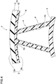
- FIG. 1 is a perspective view of a non-pneumatic tire 1 according to an embodiment.
- the non-pneumatic tire 1 for example, is employed for passenger cars or heavy load vehicles.
- the non-pneumatic tire (hereinafter, simply may refer to as "tire") 1 can support a tire load by a structural rigidity of the tire, and thus is different from a pneumatic tire in which a compressed air is to be filled therein.
- the tire 1 includes an annular tread portion 2, an inner portion 3 disposed inward of the tread portion 2 in the tire radial direction and the connecting portions 4 connecting the tread portion 2 and the inner portion 3.
- the inner portion 3 has an annular body extending continuously in the tire circumferential direction.
- the inner portion 3, for example, has a constant width and thickness in the tire width direction.
- the inner portion 3, for example, is formed of a resin material.
- the inner portion 3 is formed of polyurethane resin.
- the inner portion 3 of the tire 1, for example, is to be fixed to a wheel H, as illustrated in FIG.2 , and the wheel H differs from a wheel rim for pneumatic tires.
- the wheel H is to be fixed to an axle (not illustrated) of a vehicle.
- the connecting portions 4 are formed in plate shapes that extend in the tire width direction, and are arranged in the tire circumferential direction. That is, a plurality of connecting portions 4 is arranged in the tire circumferential direction.
- connecting portions 4 are inclined with respect to the tire radial direction.
- circumferential adjacent connecting portions 4 and 4 are inclined with respect to the tire radial direction in an opposite direction from each other.
- the radially outer ends 4a of the connecting portions 4 are fixed to the tread portion 2.
- the radially inner ends 4b of the connecting portions 4 are fixed to the inner portion 3.
- the outer ends 4a and the inner ends 4b of the connecting portions 4 extend along the tire axial direction.
- the connecting portions 4, for example, have widths Wa same as the inner portion 3.
- the shape of the connecting portions 4 is not limited to the above aspect, but it can employ various aspects such as a zigzag shape extending in the tire radial direction or the tire circumferential direction, and a mesh manner in a circumferential cross-section, for example.
- the connecting portions 4 are formed of resin or rubber material.
- the rubber material preferably has durometer type-A hardness of from 70 to 95 degrees at temperature of 23 deg. C, based on JIS K6253.
- the connecting portions 4 are made of resin material, urethane resin that has hardness capable of exerting sufficient load capacity is preferable. Such a connecting portion 4 can absorb vibration to improve riding comfort when traveling.
- the connecting portions 4 are formed of thermosetting polyurethane.
- the tread portion 2 is an annular body extending continuously in the tire circumferential direction.
- the tread portion 2 for example, has a constant width W.
- the tread portion 2 is disposed concentrically with the inner portion 3.
- the tread portion 2 includes a first portion 5 disposed outside and a second portion 6 having an inner surface 2b on the side of the inner portion 3.
- the first portion 5 includes an outer layer 7 having a tread surface 2a that comes into contact with the road surface and an inner layer 8 disposed inward of the outer layer 7 in the tire radial direction.
- the outer layer 7 and the inner layer 8 are disposed concentrically with each other.
- the outer layer 7 is an annular body extending continuously in the tire circumferential direction.
- the outer layer 7 according to the embodiment includes rubber, particularly hard rubber.
- the outer layer 7 may improve durability and riding comfort of the tire 1.
- the outer layer 7 may generate heat energy by hysteresis loss thereof to heat the first portion 5 since the outer layer 7 repeats compressive and tensile deformation.
- the outer layer 7, for example includes a reinforcing cord layer (not illustrated) in which steel or organic fiber cords are arranged.
- the inner layer 8 is an annular body extending continuously in the tire circumferential direction.
- the inner layer 8 is connected to a radially inner surface 7a of the outer layer 7.
- FIG. 3 illustrates a partial enlarged cross-sectional view of the tire 1 taken along the tire circumferential direction.
- a radially inner surface 8a of the inner layer 8 is connected to the connecting portions 4.
- the inner layer 8, for example, is formed of the same material as the connecting portions 4.
- the outer layer 7 is firmly fixed to the connecting portions 4 through the inner layer 8.
- the inner layer 8 is joined to the outer layer 7 with an adhesive.
- the inner layer 8, for example, is made of urethane resin.
- the second portion 6 covers a radially inner surface 5a of the first portion 5 at least partially.
- the second portion 6 covers the whole region of the radially inner surface 5a of the first portion 5. That is, the whole radially inner surface 2a of the tread portion 2 is covered with the second portion 6.
- the thermal conductivity k2 of the second portion 6 is set greater than the thermal conductivity k1 of the first portion 5.
- heat of the first portion 5 which is generated by grounding of the first portion 5 is dissipated smoothly to the outside the tire through the inner surface 2b of the second portion 6 which has a large thermal conductivity.
- the non-pneumatic tire 1 according to the present invention suppresses degradation in the first portion 5 of the tread portion 2 due to heat and exhibits an excellent durability. Furthermore, it may suppress degradation in the adhesive to join the outer layer 7 and the inner layer 8 to exert an excellent durability.
- the thermal conductivity k1 of the first portion 5 means the weighted average of thermal conductivities of the outer and inner layers 7 and 8 by weighting the respective volume.
- the thermal conductivity k2 of the second portion 6 is preferably twice or more the thermal conductivity k1 of the first portion 5, more preferably quadruple or more the thermal conductivity k1.
- the thermal conductivity k2 of the second portion 6 is twice or more the thermal conductivity k1 of the first portion 5, heat of the first portion 5 is transmitted smoothly to the second portion 6, and then it may be dissipated through the inner surface 2b.
- the thermal conductivity k2 of the second portion 6 is preferably equal to or more than 1.0 W/(m ⁇ K), more preferably equal to or more than 1.9 W/(m ⁇ K).
- resin such as silicone-based, urethane-based and epoxy-based, or rubber may preferably be employed, for example.
- the second portion 6 has a thickness t in a range of from 0.001 to 2 mm.
- the thickness t of the second portion 6 is less than 0.001 mm, there is a possibility that heat of the first portion 5 may not be transmitted to the second portion 6 smoothly.
- the thickness t of the second portion 6 is more than 2 mm, it may cause an increase of the tire mass as well as a reduction of the effect of heat dissipate property.
- the thickness t of the second portion 6 is preferably equal to or more than 0.01 mm, more preferably equal to or less than 1.0 mm.
- the radially inner surface 2b of the tread portion 2 includes a rough surface region 10 where the surface is roughened.
- the rough surface region 10 is useful to increase a surface area of the inner surface 2b.
- heat of the first portion 5 can be dissipated to the air more smoothly.
- embossing, graining and satin process and the like can preferably be employed.
- the rough surface region 10 according to the embodiment is provided on the whole inner surface 2b.
- the surface roughness Ra of the rough surface region 10 is in a range of from 1 to 30 ⁇ m.
- the surface roughness Ra is less than 1 ⁇ m, the effect that increases the surface area of the inner surface 2b tends to be small.
- the surface roughness Ra of the rough surface region 10 is more than 30 ⁇ m, there is a possibility that stress which is caused by compressive and tensile deformation during traveling may concentrate on a portion of the rough surface region 10 to cause a crack.
- the surface roughness Ra of the rough surface region 10 is more preferably in a range of from 2 to 20 ⁇ m.
- surface roughness is a calculation average height (a calculation average height of a roughness curve) defined >G JIS B0601: 2001, “Geometrical Product Specifications (GPS)-Surface texture: Profile method-Terms, definitions and surface texture parameters ".
- FIG. 4 illustrates a partial cross-sectional view in accordance with another embodiment of the tire 1.
- the outer surfaces 4e of the connecting portions 4 are covered with the same material as the second portion 6.
- Non-pneumatic tires having a basic structure illustrated in FIG. 1 were manufactured based on the specifications of Table 1, and then heat-generating property and crack-damage resistance of the tires were tested. Common specifications of the tires and test procedures are as follows.
- the embodiment tires had low temperature on the inner surface compared with the comparative example tire. Furthermore, it is also confirmed that the embodiment tires received less damage due to cracks than the comparative example tire. This means that the embodiment tires have a higher improved durability than that of the comparative example tire. Furthermore, a similar result was obtained in another test where rubber and resin having different thermal conductivities from those of the above test were used.
Abstract
Description
- The present invention relates to a non-pneumatic tire having an excellent durability.
- Non-pneumatic tires which comprise an annular tread portion for coming into contact with a road surface, an annular inner portion disposed inward of the tread portion in a tire radial direction and a plurality of connecting portions connecting the tread portion and the inner portion have been known. The tread portion generally includes a portion formed of rubber or resin. In such a non-pneumatic tire, when traveling, a large hysteresis loss occurs in the tread portion by being repeated compressive and tensile deformation of the tread portion. Hysteresis loss generates heat energy that heats the tread portion. The heat tends to degrade the tread portion and will cause deterioration in durability of the non-pneumatic tire.
-
- Patent Literature 1:
Japanese Unexamined Patent Application Publication No. 2008-132951 - Patent Literature 2:
Japanese Patent Publication No. 4855646 - The present invention has been made in view of the above circumstances, and has a main object to provide a non-pneumatic tire having an excellent durability. Solution to Problem
- The present invention provides a non-pneumatic tire including an annular tread portion for coming into contact with a road surface, an annular inner portion disposed inward of the tread portion in a tire radial direction, a plurality of connecting portions connecting the tread portion and the inner portion, wherein the tread portion includes a first portion that comes into contact with the road surface and a second portion including an inner surface facing the inner portion, and a thermal conductivity of the second portion is greater than a thermal conductivity of the first portion.
- The non-pneumatic tire according to the present invention, the thermal conductivity of the second portion may preferably be twice or more the thermal conductivity of the first portion.
- The non-pneumatic tire according to the present invention, the thermal conductivity of the second portion may preferably be equal to or more than 1.0 W/(m· K).
- The non-pneumatic tire according to the present invention, a thickness of the second portion may preferably be in a range of from 0.001 to 2 mm.
- The non-pneumatic tire according to the present invention, the second portion may preferably include, at least partially, a rough surface region having surface roughness in a range of from 1 to 30 µm.
- The non-pneumatic tire according to the present invention, the first portion may preferably be made of resin or rubber.
- The non-pneumatic tire according to the present invention, the first portion may preferably include an outer layer including a rubber and an inner layer disposed inward of the outer layer in the tire radial direction and made of urethane resin.
- The non-pneumatic tire according to the present invention, the second portion may preferably be made of resin such as silicone-based, urethane-based and epoxy-based, or rubber.
- The present invention provides a non-pneumatic tire including an annular tread portion for coming into contact with a road surface, an annular inner portion disposed inward of the tread portion in a tire radial direction and a plurality of connecting portions connecting the tread portion and the inner portion. The tread portion includes a first portion that comes into contact with the road surface and a second portion comprising an inner surface facing the inner portion, and a thermal conductivity of the second portion is greater than a thermal conductivity of the first portion. When grounding, the first portion is heated due to repeated compressive and tensile deformation of the tread portion. The heat of the first portion is dissipated smoothly to the outside through the inner surface of the second portion which has a large thermal conductivity. Accordingly, the non-pneumatic tire according to the present invention suppresses degradation of the tread portion due to heat and exhibits an excellent durability.
-
-
FIG. 1 is a perspective view of a non-pneumatic tire according to an embodiment of the present invention. -
FIG. 2 is a perspective view of the non-pneumatic tire ofFIG. 1 mounted on a wheel. -
FIG. 3 is a partial enlarged cross-sectional view of the non-pneumatic tire ofFIG. 1 taken along a tire circumferential direction. -
FIG. 4 is a partial enlarged cross-sectional view of the non-pneumatic tire according to another embodiment. - An embodiment of the present invention will be explained below with reference to the accompanying drawings.
-
FIG. 1 is a perspective view of a non-pneumatictire 1 according to an embodiment. Thenon-pneumatic tire 1, for example, is employed for passenger cars or heavy load vehicles. The non-pneumatic tire (hereinafter, simply may refer to as "tire") 1 can support a tire load by a structural rigidity of the tire, and thus is different from a pneumatic tire in which a compressed air is to be filled therein. - As illustrated in
FIG. 1 , thetire 1 includes anannular tread portion 2, aninner portion 3 disposed inward of thetread portion 2 in the tire radial direction and the connectingportions 4 connecting thetread portion 2 and theinner portion 3. - The
inner portion 3 has an annular body extending continuously in the tire circumferential direction. Theinner portion 3, for example, has a constant width and thickness in the tire width direction. Theinner portion 3, for example, is formed of a resin material. In this embodiment, theinner portion 3 is formed of polyurethane resin. - In this embodiment, the
inner portion 3 of thetire 1, for example, is to be fixed to a wheel H, as illustrated inFIG.2 , and the wheel H differs from a wheel rim for pneumatic tires. The wheel H is to be fixed to an axle (not illustrated) of a vehicle. - As illustrated in
FIG. 1 , the connectingportions 4 according to the embodiment are formed in plate shapes that extend in the tire width direction, and are arranged in the tire circumferential direction. That is, a plurality of connectingportions 4 is arranged in the tire circumferential direction. When a vertical load is applied to an axle, the load is supported by tensile rigidity of the connectingportions 4 located upward of the axle and compressive rigidity of the connectingportions 4 located downward of the axle. - The connecting
portions 4, for example, are inclined with respect to the tire radial direction. In this embodiment, circumferential adjacent connectingportions - The radially
outer ends 4a of the connectingportions 4 are fixed to thetread portion 2. The radiallyinner ends 4b of the connectingportions 4 are fixed to theinner portion 3. In this embodiment, theouter ends 4a and theinner ends 4b of the connectingportions 4 extend along the tire axial direction. The connectingportions 4, for example, have widths Wa same as theinner portion 3. Thus, high rigidity of the connectingportions 4 may be maintained. The shape of the connectingportions 4 is not limited to the above aspect, but it can employ various aspects such as a zigzag shape extending in the tire radial direction or the tire circumferential direction, and a mesh manner in a circumferential cross-section, for example. - The connecting
portions 4 are formed of resin or rubber material. When the connectingportions 4 are made of rubber material, the rubber material preferably has durometer type-A hardness of from 70 to 95 degrees at temperature of 23 deg. C, based on JIS K6253. When the connectingportions 4 are made of resin material, urethane resin that has hardness capable of exerting sufficient load capacity is preferable. Such a connectingportion 4 can absorb vibration to improve riding comfort when traveling. In this embodiment, the connectingportions 4 are formed of thermosetting polyurethane. - The
tread portion 2 is an annular body extending continuously in the tire circumferential direction. Thetread portion 2, for example, has a constant width W. Thetread portion 2 is disposed concentrically with theinner portion 3. - In this embodiment, the
tread portion 2 includes afirst portion 5 disposed outside and asecond portion 6 having aninner surface 2b on the side of theinner portion 3. - The
first portion 5 includes anouter layer 7 having atread surface 2a that comes into contact with the road surface and aninner layer 8 disposed inward of theouter layer 7 in the tire radial direction. Theouter layer 7 and theinner layer 8 are disposed concentrically with each other. - The
outer layer 7 is an annular body extending continuously in the tire circumferential direction. Theouter layer 7 according to the embodiment includes rubber, particularly hard rubber. Theouter layer 7 may improve durability and riding comfort of thetire 1. On the other hand, theouter layer 7 may generate heat energy by hysteresis loss thereof to heat thefirst portion 5 since theouter layer 7 repeats compressive and tensile deformation. Note that theouter layer 7, for example, includes a reinforcing cord layer (not illustrated) in which steel or organic fiber cords are arranged. - The
inner layer 8 is an annular body extending continuously in the tire circumferential direction. Theinner layer 8 is connected to a radiallyinner surface 7a of theouter layer 7. -
FIG. 3 illustrates a partial enlarged cross-sectional view of thetire 1 taken along the tire circumferential direction. As illustrated inFIG. 3 , a radiallyinner surface 8a of theinner layer 8 is connected to the connectingportions 4. Theinner layer 8, for example, is formed of the same material as the connectingportions 4. Thus, theouter layer 7 is firmly fixed to the connectingportions 4 through theinner layer 8. In this embodiment, theinner layer 8 is joined to theouter layer 7 with an adhesive. Theinner layer 8, for example, is made of urethane resin. - The
second portion 6 covers a radiallyinner surface 5a of thefirst portion 5 at least partially. In this embodiment, thesecond portion 6 covers the whole region of the radiallyinner surface 5a of thefirst portion 5. That is, the whole radiallyinner surface 2a of thetread portion 2 is covered with thesecond portion 6. - The thermal conductivity k2 of the
second portion 6 is set greater than the thermal conductivity k1 of thefirst portion 5. Thus, heat of thefirst portion 5 which is generated by grounding of thefirst portion 5 is dissipated smoothly to the outside the tire through theinner surface 2b of thesecond portion 6 which has a large thermal conductivity. Accordingly, thenon-pneumatic tire 1 according to the present invention suppresses degradation in thefirst portion 5 of thetread portion 2 due to heat and exhibits an excellent durability. Furthermore, it may suppress degradation in the adhesive to join theouter layer 7 and theinner layer 8 to exert an excellent durability. Note that the thermal conductivity k1 of thefirst portion 5 means the weighted average of thermal conductivities of the outer andinner layers - The thermal conductivity k2 of the
second portion 6 is preferably twice or more the thermal conductivity k1 of thefirst portion 5, more preferably quadruple or more the thermal conductivity k1. When the thermal conductivity k2 of thesecond portion 6 is twice or more the thermal conductivity k1 of thefirst portion 5, heat of thefirst portion 5 is transmitted smoothly to thesecond portion 6, and then it may be dissipated through theinner surface 2b. The greater the thermal conductivity k2 of thesecond portion 6 in relation to the thermal conductivity k1 of thefirst portion 5, the better the dissipate property through theinner surface 2b is. - In order to further improve the above effect, the thermal conductivity k2 of the
second portion 6 is preferably equal to or more than 1.0 W/(m·K), more preferably equal to or more than 1.9 W/(m·K). As a material for thesecond portion 6, resin such as silicone-based, urethane-based and epoxy-based, or rubber may preferably be employed, for example. - Preferably, the
second portion 6 has a thickness t in a range of from 0.001 to 2 mm. When the thickness t of thesecond portion 6 is less than 0.001 mm, there is a possibility that heat of thefirst portion 5 may not be transmitted to thesecond portion 6 smoothly. When the thickness t of thesecond portion 6 is more than 2 mm, it may cause an increase of the tire mass as well as a reduction of the effect of heat dissipate property. In view of the above, the thickness t of thesecond portion 6 is preferably equal to or more than 0.01 mm, more preferably equal to or less than 1.0 mm. - As illustrated in
FIG. 1 , the radiallyinner surface 2b of thetread portion 2 includes arough surface region 10 where the surface is roughened. Therough surface region 10 is useful to increase a surface area of theinner surface 2b. Thus, heat of thefirst portion 5 can be dissipated to the air more smoothly. As processes to make the rough surface region, embossing, graining and satin process and the like can preferably be employed. Therough surface region 10 according to the embodiment is provided on the wholeinner surface 2b. - Preferably, the surface roughness Ra of the
rough surface region 10 is in a range of from 1 to 30 µm. When the surface roughness Ra is less than 1 µm, the effect that increases the surface area of theinner surface 2b tends to be small. When the surface roughness Ra of therough surface region 10 is more than 30 µm, there is a possibility that stress which is caused by compressive and tensile deformation during traveling may concentrate on a portion of therough surface region 10 to cause a crack. Thus, the surface roughness Ra of therough surface region 10 is more preferably in a range of from 2 to 20 µm. As used herein, "surface roughness" is a calculation average height (a calculation average height of a roughness curve) defined >G JIS B0601: 2001, "Geometrical Product Specifications (GPS)-Surface texture: Profile method-Terms, definitions and surface texture parameters". -
FIG. 4 illustrates a partial cross-sectional view in accordance with another embodiment of thetire 1. As illustrated inFIG. 4 , in this embodiment, theouter surfaces 4e of the connectingportions 4 are covered with the same material as thesecond portion 6. Thus, not only internal heat of thefirst portion 5 but also internal heat of the connectingportions 4 is dissipated smoothly outside the tire, and therefore durability of thetire 1 can further be improved. - While the particularly preferable embodiments of non-pneumatic tire in accordance with the present invention have been described in detail, the present invention is not limited to the illustrated embodiments, but can be modified and carried out in various aspects.
- Non-pneumatic tires having a basic structure illustrated in
FIG. 1 were manufactured based on the specifications of Table 1, and then heat-generating property and crack-damage resistance of the tires were tested. Common specifications of the tires and test procedures are as follows. - Tire outer diameter Ha: 635 mm
- Tread portion width W: 195 mm
- Material of outer layer of first portion: natural rubber and styrene-butadiene rubber
- Material of inner layer of first portion: thermosetting polyurethane resin (thermal conductivity: 0.25 W/(m·K))
- Thermal conductivity k1 of first portion: 0.21 W/(m·K)
- Material of second portion: silicone based rubber (thermal conductivity k2: 1.9 W/(m·K))
- Material of second portion: urethane based rubber (thermal conductivity k2: 0.8 W/(m·K))
- Material of inner portion: thermosetting polyurethane resin
- Radial heights of connecting portions Hb: 90 mm
- Widths of connecting portions Wa: 185 mm
- Material of connecting portions: thermosetting polyurethane resin
- Each of the tires was made to run on a drum tester under the following conditions, and then the mean temperature of the inner surface of the tread portion was measured using a thermal image device (surface thermometer). The results are indicated in Table 1 using an index based on Ref. 1 being 100. The smaller the value, the better the property is.
- Traveling distance: 10 km
- Tire load: 4.55 kN
- Traveling speed: 60 km/hr
- Using the above mentioned drum tester, each of the tires was made to run under the following conditions, and then the inner surface of the tread portion was observed to check whether a crack is generated thereon. The results are indicated in Table 1 using a three-grade evaluation as follows. The smaller the value, the better the resistance is.
- Traveling distance: 10,000 km
- Tire load: 4.55 kN
- Traveling speed: 60 km/hr
-
- 1: No cracks occurred.
- 2: Crack(s) occurred in length less than 2 mm.
- 3: Crack(s) occurred in length equal to or more than 2 mm.
- The test results are shown in Table 1.
[Table 1] Ref. 1 Ex. 1 Ex. 2 Ex. 3 Ex. 4 Ex. 5 Ex. 6 Ex. 7 Ex. 8 Ex. 9 Ex. 10 Ex. 11 Thermal conductivity of second portion W/(m·K) - 1.9 0.8 1.0 1.9 1.9 1.9 1.9 1.9 1.9 1.9 1.9 Thickness t of second portion (mm) 0 0.5 0.5 0.5 0.001 0.1 2.0 2.5 0.5 0.5 0.5 0.5 Surface roughness Ra (µm) - 1.5 1.5 1.5 1.5 1.5 1.5 1.5 0.9 1.0 30 40 Heat generating property (index; the smaller, the better) 100 90 96 95 94 93 91 92 92 93 95 95 Crack-damage resistance (three-grade evaluation; the smaller, the better) 3 1 2 2 1 1 1 2 2 1 1 2 - From the test results, it is confirmed that the embodiment tires had low temperature on the inner surface compared with the comparative example tire. Furthermore, it is also confirmed that the embodiment tires received less damage due to cracks than the comparative example tire. This means that the embodiment tires have a higher improved durability than that of the comparative example tire. Furthermore, a similar result was obtained in another test where rubber and resin having different thermal conductivities from those of the above test were used.
-
- 1
- Non-pneumatic tire
- 2
- Tread portion
- 2b
- Inner surface
- 3
- Inner portion
- 4
- Connecting portions
- 5
- First portion
- 6
- Second portion
Claims (8)
- A non-pneumatic tire comprising:an annular tread portion for coming into contact with a road surface;an annular inner portion disposed inward of the tread portion in a tire radial direction; anda plurality of connecting portions connecting the tread portion and the inner portion;wherein the tread portion comprises a first portion that comes into contact with the road surface and a second portion comprising an inner surface facing the inner portion, and a thermal conductivity of the second portion is greater than a thermal conductivity of the first portion.
- The non-pneumatic tire according to claim 1,
wherein the thermal conductivity of the second portion is twice or more the thermal conductivity of the first portion. - The non-pneumatic tire according to claim 1 or 2,
wherein the thermal conductivity of the second portion is equal to or more than 1.0 W/(m·K). - The non-pneumatic tire according to any one of claims 1 to 3,
wherein a thickness of the second portion is in a range of from 0.001 to 2 mm. - The non-pneumatic tire according to any one of claims 1 to 4,
wherein the second portion comprises, at least partially, a rough surface region having surface roughness in a range of from 1 to 30 µm. - The non-pneumatic tire according to any one of claims 1 to 5,
wherein the first portion is made of resin or rubber. - The non-pneumatic tire according to claim 6,
wherein the first portion comprises an outer layer comprising a rubber and an inner layer disposed inward of the outer layer in the tire radial direction and made of urethane resin. - The non-pneumatic tire according to any one of claims 1 to 7,
wherein the second portion is made of resin such as silicone-based, urethane-based and epoxy-based, or rubber.
Applications Claiming Priority (2)
| Application Number | Priority Date | Filing Date | Title |
|---|---|---|---|
| JP2014106382A JP6302355B2 (en) | 2014-05-22 | 2014-05-22 | Non-pneumatic tire |
| PCT/JP2015/063201 WO2015178209A1 (en) | 2014-05-22 | 2015-05-07 | Non-pneumatic tire |
Publications (3)
| Publication Number | Publication Date |
|---|---|
| EP3147137A1 true EP3147137A1 (en) | 2017-03-29 |
| EP3147137A4 EP3147137A4 (en) | 2018-03-14 |
| EP3147137B1 EP3147137B1 (en) | 2019-10-02 |
Family
ID=54553882
Family Applications (1)
| Application Number | Title | Priority Date | Filing Date |
|---|---|---|---|
| EP15796467.7A Active EP3147137B1 (en) | 2014-05-22 | 2015-05-07 | Non-pneumatic tire |
Country Status (6)
| Country | Link |
|---|---|
| US (1) | US10507693B2 (en) |
| EP (1) | EP3147137B1 (en) |
| JP (1) | JP6302355B2 (en) |
| KR (1) | KR102352528B1 (en) |
| CN (1) | CN106457902B (en) |
| WO (1) | WO2015178209A1 (en) |
Cited By (1)
| Publication number | Priority date | Publication date | Assignee | Title |
|---|---|---|---|---|
| EP3254869A1 (en) * | 2016-06-10 | 2017-12-13 | Sumitomo Rubber Industries, Ltd. | Non-pneumatic tire |
Families Citing this family (10)
| Publication number | Priority date | Publication date | Assignee | Title |
|---|---|---|---|---|
| EP3007909A4 (en) | 2013-06-15 | 2017-03-01 | Ronald Thompson | Annular ring and non-pneumatic tire |
| JP6212381B2 (en) * | 2013-12-24 | 2017-10-11 | 住友ゴム工業株式会社 | Airless tire |
| CA2976055A1 (en) * | 2015-02-04 | 2016-08-11 | Advancing Mobility, Llc. | Non-pneumatic tire and other annular devices |
| JP6842361B2 (en) * | 2017-05-11 | 2021-03-17 | 株式会社ブリヂストン | Non-pneumatic tires |
| WO2018227276A1 (en) | 2017-06-15 | 2018-12-20 | Camso Inc. | Wheel comprising a non-pneumatic tire |
| JP2019043503A (en) * | 2017-09-07 | 2019-03-22 | Toyo Tire株式会社 | Non-pneumatic tire |
| WO2019125466A1 (en) * | 2017-12-21 | 2019-06-27 | Compagnie Generale Des Etablissements Michelin | Reinforced resilient support for a non-pneumatic tire |
| JP7187102B2 (en) | 2019-01-04 | 2022-12-12 | ブリヂストン アメリカズ タイヤ オペレーションズ、 エルエルシー | Tire tread with band layer |
| US20220072908A1 (en) * | 2019-01-04 | 2022-03-10 | Bridgestone Americas Tire Operations, Llc | Tire tread band with shim layers |
| CN113071268B (en) * | 2021-05-10 | 2022-07-05 | 季华实验室 | Spoke and tire |
Family Cites Families (16)
| Publication number | Priority date | Publication date | Assignee | Title |
|---|---|---|---|---|
| US5139066A (en) * | 1987-12-15 | 1992-08-18 | Altrack Limited | Tire construction |
| JPH04193602A (en) * | 1990-11-28 | 1992-07-13 | Bridgestone Corp | Solid rubber tire for industrial vehicle |
| US7650919B2 (en) * | 1999-12-10 | 2010-01-26 | Michelin Recherche of Technique S.A. | Non-pneumatic tire having web spokes |
| US6859923B2 (en) * | 2001-05-09 | 2005-02-22 | Sun Microsystems, Inc. | Method, system, program, and data structures for using a database to apply patches to a computer system |
| WO2003018332A1 (en) | 2001-08-24 | 2003-03-06 | Societe De Technologie Michelin | Non-pneumatic tire |
| JP2008132951A (en) * | 2006-11-29 | 2008-06-12 | Yokohama Rubber Co Ltd:The | Non-pneumatic tire |
| US8104524B2 (en) * | 2007-03-27 | 2012-01-31 | Resilient Technologies Llc | Tension-based non-pneumatic tire |
| US8651156B2 (en) * | 2009-06-24 | 2014-02-18 | Compagnie Generale Des Etablissements Michelin | Honeycomb structures for high shear flexure |
| JP5436365B2 (en) | 2010-08-09 | 2014-03-05 | 東洋ゴム工業株式会社 | Non-pneumatic tire |
| JP2012131254A (en) * | 2010-12-20 | 2012-07-12 | Sumitomo Rubber Ind Ltd | Run-flat tire |
| JP5774406B2 (en) * | 2011-08-01 | 2015-09-09 | 東洋ゴム工業株式会社 | Non-pneumatic tire |
| US9573422B2 (en) * | 2012-03-15 | 2017-02-21 | Polaris Industries Inc. | Non-pneumatic tire |
| WO2014188912A1 (en) * | 2013-05-22 | 2014-11-27 | 住友ゴム工業株式会社 | Airless tire and method for manufacturing same |
| EP3002133B1 (en) * | 2013-06-11 | 2019-12-04 | Sumitomo Rubber Industries, Ltd. | Non-pneumatic tire |
| US10040314B2 (en) * | 2015-12-07 | 2018-08-07 | The Goodyear Tire & Rubber Company | Non-pneumatic tire |
| JP6701997B2 (en) * | 2016-06-10 | 2020-05-27 | 住友ゴム工業株式会社 | Non-pneumatic tire |
-
2014
- 2014-05-22 JP JP2014106382A patent/JP6302355B2/en active Active
-
2015
- 2015-05-07 US US15/307,942 patent/US10507693B2/en active Active
- 2015-05-07 WO PCT/JP2015/063201 patent/WO2015178209A1/en active Application Filing
- 2015-05-07 EP EP15796467.7A patent/EP3147137B1/en active Active
- 2015-05-07 KR KR1020167032909A patent/KR102352528B1/en active IP Right Grant
- 2015-05-07 CN CN201580024157.0A patent/CN106457902B/en active Active
Cited By (1)
| Publication number | Priority date | Publication date | Assignee | Title |
|---|---|---|---|---|
| EP3254869A1 (en) * | 2016-06-10 | 2017-12-13 | Sumitomo Rubber Industries, Ltd. | Non-pneumatic tire |
Also Published As
| Publication number | Publication date |
|---|---|
| EP3147137B1 (en) | 2019-10-02 |
| WO2015178209A1 (en) | 2015-11-26 |
| US10507693B2 (en) | 2019-12-17 |
| CN106457902B (en) | 2018-12-14 |
| CN106457902A (en) | 2017-02-22 |
| JP6302355B2 (en) | 2018-03-28 |
| US20170057288A1 (en) | 2017-03-02 |
| KR20170010310A (en) | 2017-01-26 |
| EP3147137A4 (en) | 2018-03-14 |
| KR102352528B1 (en) | 2022-01-19 |
| JP2015221608A (en) | 2015-12-10 |
Similar Documents
| Publication | Publication Date | Title |
|---|---|---|
| EP3147137B1 (en) | Non-pneumatic tire | |
| EP3002133B1 (en) | Non-pneumatic tire | |
| EP3009273B1 (en) | Airless tire | |
| EP3141402B1 (en) | Tire | |
| JP6423584B2 (en) | Non-pneumatic tire | |
| JP4818220B2 (en) | Non-pneumatic tire and manufacturing method thereof | |
| JP2017081199A (en) | Airless tire | |
| BR122019009686B1 (en) | non-pneumatic tires | |
| JP2009035050A (en) | Non-pneumatic pressure tire | |
| EP3446887A1 (en) | Airless tire | |
| CN104626884B (en) | A kind of on-inflatable safety tread | |
| JP2017218132A (en) | Non-pneumatic tire | |
| JP2015151006A (en) | Non-air pressure tire | |
| JP6582581B2 (en) | Non-pneumatic tire | |
| JP6081776B2 (en) | Non-pneumatic tire | |
| EP3318417A1 (en) | Tire | |
| JP6597738B2 (en) | Non-pneumatic tire | |
| RU2397877C1 (en) | Car tyre of elastic polyurethane with elastic deformable spokes | |
| TW201604045A (en) | Wheel | |
| EP3441238B1 (en) | Tire | |
| JP2017100640A (en) | Non-pneumatic tire |
Legal Events
| Date | Code | Title | Description |
|---|---|---|---|
| STAA | Information on the status of an ep patent application or granted ep patent |
Free format text: STATUS: THE INTERNATIONAL PUBLICATION HAS BEEN MADE |
|
| PUAI | Public reference made under article 153(3) epc to a published international application that has entered the european phase |
Free format text: ORIGINAL CODE: 0009012 |
|
| STAA | Information on the status of an ep patent application or granted ep patent |
Free format text: STATUS: REQUEST FOR EXAMINATION WAS MADE |
|
| 17P | Request for examination filed |
Effective date: 20161031 |
|
| AK | Designated contracting states |
Kind code of ref document: A1 Designated state(s): AL AT BE BG CH CY CZ DE DK EE ES FI FR GB GR HR HU IE IS IT LI LT LU LV MC MK MT NL NO PL PT RO RS SE SI SK SM TR |
|
| AX | Request for extension of the european patent |
Extension state: BA ME |
|
| DAV | Request for validation of the european patent (deleted) | ||
| DAX | Request for extension of the european patent (deleted) | ||
| A4 | Supplementary search report drawn up and despatched |
Effective date: 20180212 |
|
| RIC1 | Information provided on ipc code assigned before grant |
Ipc: B60C 7/10 20060101ALI20180206BHEP Ipc: B60C 11/00 20060101ALI20180206BHEP Ipc: B60B 9/04 20060101ALI20180206BHEP Ipc: B60B 9/26 20060101ALI20180206BHEP Ipc: B60C 7/14 20060101ALI20180206BHEP Ipc: B60C 7/00 20060101AFI20180206BHEP |
|
| GRAP | Despatch of communication of intention to grant a patent |
Free format text: ORIGINAL CODE: EPIDOSNIGR1 |
|
| STAA | Information on the status of an ep patent application or granted ep patent |
Free format text: STATUS: GRANT OF PATENT IS INTENDED |
|
| INTG | Intention to grant announced |
Effective date: 20190424 |
|
| GRAS | Grant fee paid |
Free format text: ORIGINAL CODE: EPIDOSNIGR3 |
|
| GRAA | (expected) grant |
Free format text: ORIGINAL CODE: 0009210 |
|
| STAA | Information on the status of an ep patent application or granted ep patent |
Free format text: STATUS: THE PATENT HAS BEEN GRANTED |
|
| AK | Designated contracting states |
Kind code of ref document: B1 Designated state(s): AL AT BE BG CH CY CZ DE DK EE ES FI FR GB GR HR HU IE IS IT LI LT LU LV MC MK MT NL NO PL PT RO RS SE SI SK SM TR |
|
| REG | Reference to a national code |
Ref country code: GB Ref legal event code: FG4D |
|
| REG | Reference to a national code |
Ref country code: CH Ref legal event code: EP Ref country code: AT Ref legal event code: REF Ref document number: 1185767 Country of ref document: AT Kind code of ref document: T Effective date: 20191015 |
|
| REG | Reference to a national code |
Ref country code: DE Ref legal event code: R096 Ref document number: 602015039161 Country of ref document: DE |
|
| REG | Reference to a national code |
Ref country code: IE Ref legal event code: FG4D |
|
| REG | Reference to a national code |
Ref country code: NL Ref legal event code: MP Effective date: 20191002 |
|
| REG | Reference to a national code |
Ref country code: LT Ref legal event code: MG4D |
|
| REG | Reference to a national code |
Ref country code: AT Ref legal event code: MK05 Ref document number: 1185767 Country of ref document: AT Kind code of ref document: T Effective date: 20191002 |
|
| PG25 | Lapsed in a contracting state [announced via postgrant information from national office to epo] |
Ref country code: LV Free format text: LAPSE BECAUSE OF FAILURE TO SUBMIT A TRANSLATION OF THE DESCRIPTION OR TO PAY THE FEE WITHIN THE PRESCRIBED TIME-LIMIT Effective date: 20191002 Ref country code: SE Free format text: LAPSE BECAUSE OF FAILURE TO SUBMIT A TRANSLATION OF THE DESCRIPTION OR TO PAY THE FEE WITHIN THE PRESCRIBED TIME-LIMIT Effective date: 20191002 Ref country code: AT Free format text: LAPSE BECAUSE OF FAILURE TO SUBMIT A TRANSLATION OF THE DESCRIPTION OR TO PAY THE FEE WITHIN THE PRESCRIBED TIME-LIMIT Effective date: 20191002 Ref country code: NL Free format text: LAPSE BECAUSE OF FAILURE TO SUBMIT A TRANSLATION OF THE DESCRIPTION OR TO PAY THE FEE WITHIN THE PRESCRIBED TIME-LIMIT Effective date: 20191002 Ref country code: NO Free format text: LAPSE BECAUSE OF FAILURE TO SUBMIT A TRANSLATION OF THE DESCRIPTION OR TO PAY THE FEE WITHIN THE PRESCRIBED TIME-LIMIT Effective date: 20200102 Ref country code: PL Free format text: LAPSE BECAUSE OF FAILURE TO SUBMIT A TRANSLATION OF THE DESCRIPTION OR TO PAY THE FEE WITHIN THE PRESCRIBED TIME-LIMIT Effective date: 20191002 Ref country code: GR Free format text: LAPSE BECAUSE OF FAILURE TO SUBMIT A TRANSLATION OF THE DESCRIPTION OR TO PAY THE FEE WITHIN THE PRESCRIBED TIME-LIMIT Effective date: 20200103 Ref country code: LT Free format text: LAPSE BECAUSE OF FAILURE TO SUBMIT A TRANSLATION OF THE DESCRIPTION OR TO PAY THE FEE WITHIN THE PRESCRIBED TIME-LIMIT Effective date: 20191002 Ref country code: ES Free format text: LAPSE BECAUSE OF FAILURE TO SUBMIT A TRANSLATION OF THE DESCRIPTION OR TO PAY THE FEE WITHIN THE PRESCRIBED TIME-LIMIT Effective date: 20191002 Ref country code: FI Free format text: LAPSE BECAUSE OF FAILURE TO SUBMIT A TRANSLATION OF THE DESCRIPTION OR TO PAY THE FEE WITHIN THE PRESCRIBED TIME-LIMIT Effective date: 20191002 Ref country code: BG Free format text: LAPSE BECAUSE OF FAILURE TO SUBMIT A TRANSLATION OF THE DESCRIPTION OR TO PAY THE FEE WITHIN THE PRESCRIBED TIME-LIMIT Effective date: 20200102 Ref country code: PT Free format text: LAPSE BECAUSE OF FAILURE TO SUBMIT A TRANSLATION OF THE DESCRIPTION OR TO PAY THE FEE WITHIN THE PRESCRIBED TIME-LIMIT Effective date: 20200203 |
|
| PG25 | Lapsed in a contracting state [announced via postgrant information from national office to epo] |
Ref country code: HR Free format text: LAPSE BECAUSE OF FAILURE TO SUBMIT A TRANSLATION OF THE DESCRIPTION OR TO PAY THE FEE WITHIN THE PRESCRIBED TIME-LIMIT Effective date: 20191002 Ref country code: RS Free format text: LAPSE BECAUSE OF FAILURE TO SUBMIT A TRANSLATION OF THE DESCRIPTION OR TO PAY THE FEE WITHIN THE PRESCRIBED TIME-LIMIT Effective date: 20191002 Ref country code: IS Free format text: LAPSE BECAUSE OF FAILURE TO SUBMIT A TRANSLATION OF THE DESCRIPTION OR TO PAY THE FEE WITHIN THE PRESCRIBED TIME-LIMIT Effective date: 20200224 Ref country code: CZ Free format text: LAPSE BECAUSE OF FAILURE TO SUBMIT A TRANSLATION OF THE DESCRIPTION OR TO PAY THE FEE WITHIN THE PRESCRIBED TIME-LIMIT Effective date: 20191002 |
|
| PG25 | Lapsed in a contracting state [announced via postgrant information from national office to epo] |
Ref country code: AL Free format text: LAPSE BECAUSE OF FAILURE TO SUBMIT A TRANSLATION OF THE DESCRIPTION OR TO PAY THE FEE WITHIN THE PRESCRIBED TIME-LIMIT Effective date: 20191002 |
|
| REG | Reference to a national code |
Ref country code: DE Ref legal event code: R097 Ref document number: 602015039161 Country of ref document: DE |
|
| PG2D | Information on lapse in contracting state deleted |
Ref country code: IS |
|
| PG25 | Lapsed in a contracting state [announced via postgrant information from national office to epo] |
Ref country code: DK Free format text: LAPSE BECAUSE OF FAILURE TO SUBMIT A TRANSLATION OF THE DESCRIPTION OR TO PAY THE FEE WITHIN THE PRESCRIBED TIME-LIMIT Effective date: 20191002 Ref country code: EE Free format text: LAPSE BECAUSE OF FAILURE TO SUBMIT A TRANSLATION OF THE DESCRIPTION OR TO PAY THE FEE WITHIN THE PRESCRIBED TIME-LIMIT Effective date: 20191002 Ref country code: RO Free format text: LAPSE BECAUSE OF FAILURE TO SUBMIT A TRANSLATION OF THE DESCRIPTION OR TO PAY THE FEE WITHIN THE PRESCRIBED TIME-LIMIT Effective date: 20191002 Ref country code: IS Free format text: LAPSE BECAUSE OF FAILURE TO SUBMIT A TRANSLATION OF THE DESCRIPTION OR TO PAY THE FEE WITHIN THE PRESCRIBED TIME-LIMIT Effective date: 20200202 |
|
| PLBE | No opposition filed within time limit |
Free format text: ORIGINAL CODE: 0009261 |
|
| STAA | Information on the status of an ep patent application or granted ep patent |
Free format text: STATUS: NO OPPOSITION FILED WITHIN TIME LIMIT |
|
| PG25 | Lapsed in a contracting state [announced via postgrant information from national office to epo] |
Ref country code: SK Free format text: LAPSE BECAUSE OF FAILURE TO SUBMIT A TRANSLATION OF THE DESCRIPTION OR TO PAY THE FEE WITHIN THE PRESCRIBED TIME-LIMIT Effective date: 20191002 Ref country code: IT Free format text: LAPSE BECAUSE OF FAILURE TO SUBMIT A TRANSLATION OF THE DESCRIPTION OR TO PAY THE FEE WITHIN THE PRESCRIBED TIME-LIMIT Effective date: 20191002 Ref country code: SM Free format text: LAPSE BECAUSE OF FAILURE TO SUBMIT A TRANSLATION OF THE DESCRIPTION OR TO PAY THE FEE WITHIN THE PRESCRIBED TIME-LIMIT Effective date: 20191002 |
|
| 26N | No opposition filed |
Effective date: 20200703 |
|
| PG25 | Lapsed in a contracting state [announced via postgrant information from national office to epo] |
Ref country code: SI Free format text: LAPSE BECAUSE OF FAILURE TO SUBMIT A TRANSLATION OF THE DESCRIPTION OR TO PAY THE FEE WITHIN THE PRESCRIBED TIME-LIMIT Effective date: 20191002 |
|
| PG25 | Lapsed in a contracting state [announced via postgrant information from national office to epo] |
Ref country code: CH Free format text: LAPSE BECAUSE OF NON-PAYMENT OF DUE FEES Effective date: 20200531 Ref country code: MC Free format text: LAPSE BECAUSE OF FAILURE TO SUBMIT A TRANSLATION OF THE DESCRIPTION OR TO PAY THE FEE WITHIN THE PRESCRIBED TIME-LIMIT Effective date: 20191002 Ref country code: LI Free format text: LAPSE BECAUSE OF NON-PAYMENT OF DUE FEES Effective date: 20200531 |
|
| REG | Reference to a national code |
Ref country code: BE Ref legal event code: MM Effective date: 20200531 |
|
| GBPC | Gb: european patent ceased through non-payment of renewal fee |
Effective date: 20200507 |
|
| PG25 | Lapsed in a contracting state [announced via postgrant information from national office to epo] |
Ref country code: LU Free format text: LAPSE BECAUSE OF NON-PAYMENT OF DUE FEES Effective date: 20200507 |
|
| PG25 | Lapsed in a contracting state [announced via postgrant information from national office to epo] |
Ref country code: GB Free format text: LAPSE BECAUSE OF NON-PAYMENT OF DUE FEES Effective date: 20200507 Ref country code: IE Free format text: LAPSE BECAUSE OF NON-PAYMENT OF DUE FEES Effective date: 20200507 |
|
| PG25 | Lapsed in a contracting state [announced via postgrant information from national office to epo] |
Ref country code: BE Free format text: LAPSE BECAUSE OF NON-PAYMENT OF DUE FEES Effective date: 20200531 |
|
| PG25 | Lapsed in a contracting state [announced via postgrant information from national office to epo] |
Ref country code: TR Free format text: LAPSE BECAUSE OF FAILURE TO SUBMIT A TRANSLATION OF THE DESCRIPTION OR TO PAY THE FEE WITHIN THE PRESCRIBED TIME-LIMIT Effective date: 20191002 Ref country code: MT Free format text: LAPSE BECAUSE OF FAILURE TO SUBMIT A TRANSLATION OF THE DESCRIPTION OR TO PAY THE FEE WITHIN THE PRESCRIBED TIME-LIMIT Effective date: 20191002 Ref country code: CY Free format text: LAPSE BECAUSE OF FAILURE TO SUBMIT A TRANSLATION OF THE DESCRIPTION OR TO PAY THE FEE WITHIN THE PRESCRIBED TIME-LIMIT Effective date: 20191002 |
|
| PG25 | Lapsed in a contracting state [announced via postgrant information from national office to epo] |
Ref country code: MK Free format text: LAPSE BECAUSE OF FAILURE TO SUBMIT A TRANSLATION OF THE DESCRIPTION OR TO PAY THE FEE WITHIN THE PRESCRIBED TIME-LIMIT Effective date: 20191002 |
|
| REG | Reference to a national code |
Ref country code: FR Ref legal event code: PLFP Year of fee payment: 9 |
|
| P01 | Opt-out of the competence of the unified patent court (upc) registered |
Effective date: 20230510 |
|
| PGFP | Annual fee paid to national office [announced via postgrant information from national office to epo] |
Ref country code: FR Payment date: 20230411 Year of fee payment: 9 Ref country code: DE Payment date: 20230331 Year of fee payment: 9 |