EP3147088A1 - Gripper with conformal spring fingers - Google Patents
Gripper with conformal spring fingers Download PDFInfo
- Publication number
- EP3147088A1 EP3147088A1 EP16185111.8A EP16185111A EP3147088A1 EP 3147088 A1 EP3147088 A1 EP 3147088A1 EP 16185111 A EP16185111 A EP 16185111A EP 3147088 A1 EP3147088 A1 EP 3147088A1
- Authority
- EP
- European Patent Office
- Prior art keywords
- gripper
- section
- recited
- beam member
- beam members
- Prior art date
- Legal status (The legal status is an assumption and is not a legal conclusion. Google has not performed a legal analysis and makes no representation as to the accuracy of the status listed.)
- Withdrawn
Links
- 239000000463 material Substances 0.000 description 12
- 238000000034 method Methods 0.000 description 6
- 229910000639 Spring steel Inorganic materials 0.000 description 3
- RTAQQCXQSZGOHL-UHFFFAOYSA-N Titanium Chemical compound [Ti] RTAQQCXQSZGOHL-UHFFFAOYSA-N 0.000 description 3
- 238000009760 electrical discharge machining Methods 0.000 description 3
- 238000001125 extrusion Methods 0.000 description 3
- 239000011213 glass-filled polymer Substances 0.000 description 3
- 238000003754 machining Methods 0.000 description 3
- 229920000642 polymer Polymers 0.000 description 3
- 229910001220 stainless steel Inorganic materials 0.000 description 3
- 239000010935 stainless steel Substances 0.000 description 3
- 229910052719 titanium Inorganic materials 0.000 description 3
- 239000010936 titanium Substances 0.000 description 3
- XLYOFNOQVPJJNP-UHFFFAOYSA-N water Substances O XLYOFNOQVPJJNP-UHFFFAOYSA-N 0.000 description 3
- 238000009763 wire-cut EDM Methods 0.000 description 3
- 230000009286 beneficial effect Effects 0.000 description 2
- 230000001815 facial effect Effects 0.000 description 1
- 238000012986 modification Methods 0.000 description 1
- 230000004048 modification Effects 0.000 description 1
Images



Classifications
-
- B—PERFORMING OPERATIONS; TRANSPORTING
- B25—HAND TOOLS; PORTABLE POWER-DRIVEN TOOLS; MANIPULATORS
- B25J—MANIPULATORS; CHAMBERS PROVIDED WITH MANIPULATION DEVICES
- B25J15/00—Gripping heads and other end effectors
- B25J15/08—Gripping heads and other end effectors having finger members
- B25J15/12—Gripping heads and other end effectors having finger members with flexible finger members
-
- B—PERFORMING OPERATIONS; TRANSPORTING
- B25—HAND TOOLS; PORTABLE POWER-DRIVEN TOOLS; MANIPULATORS
- B25J—MANIPULATORS; CHAMBERS PROVIDED WITH MANIPULATION DEVICES
- B25J15/00—Gripping heads and other end effectors
- B25J15/0028—Gripping heads and other end effectors with movable, e.g. pivoting gripping jaw surfaces
-
- B—PERFORMING OPERATIONS; TRANSPORTING
- B25—HAND TOOLS; PORTABLE POWER-DRIVEN TOOLS; MANIPULATORS
- B25J—MANIPULATORS; CHAMBERS PROVIDED WITH MANIPULATION DEVICES
- B25J15/00—Gripping heads and other end effectors
- B25J15/0033—Gripping heads and other end effectors with gripping surfaces having special shapes
-
- B—PERFORMING OPERATIONS; TRANSPORTING
- B25—HAND TOOLS; PORTABLE POWER-DRIVEN TOOLS; MANIPULATORS
- B25J—MANIPULATORS; CHAMBERS PROVIDED WITH MANIPULATION DEVICES
- B25J15/00—Gripping heads and other end effectors
- B25J15/0033—Gripping heads and other end effectors with gripping surfaces having special shapes
- B25J15/0042—V-shaped gripping surfaces
Definitions
- the present invention is directed to a gripper which conforms to different shapes.
- the invention is directed to a robotic gripper with conformal spring fingers.
- a common tool that is used on manipulators mounted on robots is a gripper, which allows the robot to grasp and move objects to fulfill their operational requirements.
- no single gripper design is optimal for all tasks or for all objects, since their tasks and the shape and size of the object with which they interact may change frequently.
- One way to customize a gripper for a specific task or a specific object is to design a set of fingers, also called jaws, for the gripper that is specific to that task or object.
- a task requiring a robot to reach deep inside a narrow opening might benefit by having a set of long, narrow fingers.
- long, narrow fingers would not be suited to lifting and controlling large parts, where a shorter, broader finger would provide optimal control.
- a gripper with a compliant gripping facial surface is desirable.
- various gripper fingers may be used depending upon the application. For example, while grippers with parallel gripping surface are often used, various parts are better gripped with grippers having a shaped gripper surface. Consequently, as the grippers must be replaced for various parts, a technician must be employed to replace the fingers. This requires time, materials and special tools.
- the solution to the problem is provided by a clamp arm or gripper as described herein for use in automated equipment which can pick up or manipulate a large variety of objects or parts of different shapes.
- the gripper section includes a plurality of beam members which extend from a base, with each beam member of the plurality of beam members having a fixed end and a free end.
- the gripper section also includes a plurality of gripper surfaces proximate to the free ends, with each gripper surface attached to a respective beam member of the plurality of beam member.
- Each gripper surface of the plurality of gripper surfaces and its respective beam member move independently of the other plurality of gripper surfaces and plurality of beam members.
- the plurality of gripper surfaces and the plurality of beam members conform to the shape of an object/part to be manipulated by the gripper section.
- a clamp arm or gripper 10 is shown.
- the clamp arm 10 may be used with automated equipment, such as, but not limited to, robotic equipment.
- the clamp arm 10 can pick up or manipulate a large variety of objects or parts of different shapes (not shown).
- the clamp arm or gripper 10 can conform to the object or part being picked up or engaged.
- gripper surfaces conform to the object or part based upon the shape of the object or part and/or the force required to manipulate the object or part, as will be more fully described.
- the clamp arms 10 may be mounted to known apparatus for performing automated functions.
- apparatus may include a motor, a clamp arm mounting members and linkages to connect the motor to the clamp arm mounting members.
- motor a motor
- clamp arm mounting members and linkages to connect the motor to the clamp arm mounting members.
- linkages to connect the motor to the clamp arm mounting members.
- each clamp arm 10 has a mounting section 12, an extension section 14 and a gripper section 16.
- the mounting section 12 has openings 18 which extend therethrough. The openings 18 are configured to receive mounting hardware (not shown) therein to mount the mounting section 12 to the clamp arm mounting members.
- mounting hardware not shown
- other configurations of the mounting section 12 can be used without departing from the scope of the invention.
- the extension section 14 is connected to the gripper section 16 by means of mounting hardware 20.
- the gripper section 16 may be fastened to the extension section 14 by other means or alternatively, the gripper section 16 may be made in one piece with the extension section 14.
- the gripper section 16 includes a first beam member or spring arm 30 and a second beam member or spring arm 32 which extends from a base 22 of the gripper section 16.
- the first spring arm 30 has a fixed end 34.
- a first section 36 extends from the fixed end 34.
- a bend 38 is provided between the first section 36 and a second section 40.
- a free end 42 is provided at the end of the second section 40 which is remote from the bend 38.
- Gripper surfaces 44 are provided proximate to and/or adjacent to the free end 42.
- a positioning member 46 is provided proximate the free end 42.
- the positioning member 46 is provided in recess 48 of the gripper section 16.
- the second section 40 has an engagement portion 50 which cooperates with a surface 52 of gripper section 16.
- the second spring arm 32 has a fixed end 54.
- a first section 56 extends from the fixed end 54.
- a bend 58 is provided between the first section 56 and a second section 60.
- a free end 62 is provided at the end of the second section 60 which is remote from the bend 58.
- Gripper surfaces 64 are provided proximate to and/or adjacent to the free end 62.
- a positioning member 66 is provided proximate the free end 62. The positioning member 66 is provided in the recess 48 of the gripper section 16.
- the second section 60 has an engagement portion 70 which cooperates with a surface 72 of gripper section 16.
- Each gripper surface 44, 64 may have grooves, serrations or projections 74 provided thereon.
- the grooves, serrations or projections 74 are provided to facilitate the gripping of the object/part by the gripper surfaces 44, 64.
- a stop surface 76 is provided on the gripper section 16.
- the stop surfaces 76 of adjacent gripper sections 16 cooperate with each other to prevent the gripper sections 16 and the clamp arms 10 from moving too closely together, thereby preventing the overstress of the first spring arms 30.
- a pair of clamp arms 10 are moved together to manipulate or engage an object/part.
- the gripper surfaces 44, 64 engage the object/part.
- the gripper surfaces 44, 64 are attached to the first and second spring arms 30, 32 respectively, the gripper surfaces 44 and the first spring arms 30 move independently of the gripper surfaces 46 and the second spring arms 32. This allows each of the gripper surfaces 46, 66 to move, pivot or rotate to better accommodate or conform to the shape of the object/part to be manipulated.
- the gripper surfaces 44, 64 can move, pivot or rotate about positioning members 46, 66, thereby maintaining the positioning members 46, 66 in the recesses 48. This allows the respective adjacent gripper surfaces 44, 64 to move, pivot or rotate while being maintained in position relative to each other, thereby preventing the object/part from being inadvertently moved between the gripper surfaces 44, 64.
- the portion 50 of the second section 40 of the first arm 30 engages the surface 52 of gripper section 16 to provide increased grip force while controlling the over deflection of the first arm 30.
- the portion 70 of the second section 60 of the second arm 32 engages the surface 72 of gripper section 16 to provide increased grip force while controlling the over deflection of the second arm 32.
- the gripper surfaces 44, 64 are angled relative to each other. This allows the gripper surfaces 44, 64 to influence the movement of the object/part to the center of the gripper surfaces 44, 64, thereby providing a more stable grip of the object/part.
- the gripper surfaces 44, 64 may have a parallel configuration without departing from the scope of the invention.
- the gripper section 16 may be formed from any material having the appropriate strength, resilient (good spring properties), and weight (light weight) characteristics. Such material includes, but is not limited to, titanium, spring steel, stainless steel, polymers and glass filled plastic.
- the first and second spring arms 30, 32 may be formed by removing material using machining, wire electrical discharge machining (EDM), lasers, water jets or other known methods. Alternatively, first and second spring arms 30, 32 may be formed by stamping, extrusion molding or other known methods.
- the gripper section 316 includes a first beam member or spring arm 330 and a second beam member or spring arm 332.
- the first spring arm 330 has a fixed end 334.
- a first section 336 extends from the fixed end 334.
- a bend 338 is provided between the first section 336 and a second section 340.
- a free end 342 is provided at the end of the second section 340 which is remote from the bend 338.
- Gripper surfaces 344 are provided proximate to and/or adjacent to the free end 342.
- a positioning member 346 is provided proximate the free end 342.
- the positioning member 346 is provided proximate a surface 348 of the gripper section 316.
- the second spring arm 332 has a fixed end 354.
- a first section 356 extends from the fixed end 354.
- a bend 358 is provided between the first section 356 and a second section 360.
- a free end 362 is provided at the end of the second section 360 which is remote from the bend 358.
- Gripper surfaces 364 are provided proximate to and/or adjacent to the free end 362.
- Each gripper surface 344, 364 may have grooves, serrations or projections 374 provided thereon.
- the grooves, serrations or projections 374 are provided to facilitate the gripping of the object/part by the gripper surfaces 344, 364.
- a pair of clamp arms are moved together to manipulate or engage an object/part.
- the gripper surfaces 344, 364 engage the object/part.
- the gripper surfaces 344, 364 are attached to the first and second spring arms 330, 332 respectively, the gripper surfaces 344 and the first spring arms 330 move independently of the gripper surfaces 344 and the second spring arms 332. This allows each of the gripper surfaces 344, 364 to move, pivot or rotate to better accommodate or conform to the shape of the object/part to be manipulated.
- a portion 350 of the first section 336 or the bend 338 of the first arm 330 engages a portion 370 of the first section 356 or bend 358 of the second arm 332 to provide increased grip force while controlling the over deflection of the first arm 330.
- the amount of force provided by the first arm 330 and second arm 332 can be determined or adjusted by changing the width, length or configuration of the spring arms.
- the gripper surfaces 344, 364 are angled relative to each other. This allows the gripper surfaces 344, 364 to influence the movement of the object/part to the center of the gripper surfaces 344, 364, thereby providing a more stable grip of the object/part.
- the angled gripper surfaces 344, 334 also facilitate the holding and manipulation of objects/parts with round sections.
- the gripper surfaces 344, 364 may have a parallel configuration without departing from the scope of the invention.
- the gripper section 316 may be formed from any material having the appropriate strength, resilient (good spring properties) and weight (light weight) characteristics. Such material includes, but is not limited to, titanium, spring steel, stainless steel, polymers and glass filled plastic.
- the first and second spring arms 330, 332 may be formed by removing material using machining, wire electrical discharge machining (EDM), lasers, water jets or other known methods. Alternatively, first and second spring arms 330, 332 may be formed by stamping, extrusion molding or other known methods.
- the gripper section 416 includes a first beam member or spring arm 429, a second beam member or spring arm 430, a third beam member or spring arm 431, a fourth beam member or spring arm 432 and a fifth beam member or spring arm 433. While five spring arms are provided on each gripper section 416, other numbers of spring arms may be provided without departing from the scope of the invention.
- Each spring arm 429, 430, 431, 432, 433 has a fixed end 434a - 434e.
- First sections 436a - 436e extend from the fixed ends 434a - 434e.
- Bends 438a - 438e are provided between the first sections 436a - 436e and second sections 440a - 440e. Free ends 442a - 442e are provided at the end of the second sections 440a - 440e which are remote from the bends 438a - 438e. Gripper surfaces 444a - 444e are provided proximate to and/or adjacent to the free end 442a - 442e.
- Each gripper surface 444a - 444e may have grooves, serrations or projections 474 provided thereon.
- the grooves, serrations or projections 474 are provided to facilitate the gripping of the object/part by the gripper surfaces 444a - 444e.
- a pair of clamp arms are moved together to manipulate or engage an object/part.
- the gripper surfaces 444a - 444e of each clamp engage the object/part.
- the gripper surfaces 444a - 444e are attached to the spring arms 429 - 433 respectively, the gripper surfaces 444a - 444e and their respective spring arms 429 - 433 move independently of the other gripper surfaces 444a - 444e and their respective spring arms 429 - 433. This allows each of the gripper surfaces 444a - 444e to move, pivot or rotate to better accommodate or conform to the shape of the object/part to be manipulated.
- a portion 450a - 450d of the first sections 436a - 436d or the bends 438a - 438d of the arms 429 - 432 engage respective portions 470b - 470e of the first section 436b - 436e or bends 438b - 438e of the second arms 430 - 433 to provide increased grip force while controlling the over deflection of the first arm 430.
- the amount of force provided by the arms 429 - 433 can be determined or adjusted by changing the width, length or configuration of the spring arms.
- the gripper surfaces 444a and 444e are angled relative to each other and relative to the other gripper surfaces 444b - 444d. This allows the gripper surfaces 444a and 444e to influence the movement of the object/part to the center of the gripper surfaces and toward the parallel gripper surfaces 444b - 444d, thereby providing a more stable grip of the object/part.
- the gripper surfaces 444a and 444e may have a parallel configuration and gripper surfaces 444b - 444d may have angled surfaces without departing from the scope of the invention.
- the gripper section 416 may be formed from any material having the appropriate strength, resilient (good spring properties) and weight (light weight) characteristics. Such material includes, but is not limited to, titanium, spring steel, stainless steel, polymers and glass filled plastic.
- the spring arms 429 - 433 may be formed be removing material using machining, wire electrical discharge machining (EDM), lasers, water jets or other known methods. Alternatively, the spring arms 429 - 433 may be formed by stamping, extrusion molding or other known methods.
- Gripper section 516 has many similarities to gripper section 416. However, the gripper surface 544a has a modified configuration as compared to gripper surface and 444a.
- the gripper section 616 includes a first beam member or spring arm 627, a second beam member or spring arm 628, a third beam member or spring arm 629, a fourth beam member or spring arm 630, a fifth beam member or spring arm 631, a sixth beam member or spring arm 632 and a seventh beam member or spring arm 633. While seven spring arms are provided on each gripper section 616, other numbers of spring arms may be provided without departing from the scope of the invention. Each spring arm 627, 628, 629, 630, 631, 632, 633 and the operation thereof is similar to the spring arms 429 through 433 and the operation thereof.
- the gripper surfaces 644a - 644g are essentially in-line and parallel relative to each other. However, some or all of the gripper surfaces 644a - 644g may have angled surfaces without departing from the scope of the invention.
- the gripper section 716 has a thinner profile than the gripper section 616 to allow the gripper section 716 to have a longer reach.
- the gripper section 716 includes a first beam member or spring arm 727, a second beam member or spring arm 728, a third beam member or spring arm 729, a fourth beam member or spring arm 730, a fifth beam member or spring arm 731 and a sixth beam member or spring arm 732. While six spring arms are provided on each gripper section 716, other numbers of spring arms may be provided without departing from the scope of the invention.
- Each spring arm 727, 728, 729, 730, 731, 732 and the operation thereof is similar to the spring arms 429 through 433 and the operation thereof.
- the gripper surfaces 744a - 744f are essentially in-line and parallel relative to each other. However, some or all of the gripper surfaces 744a - 744f may have angled surfaces without departing from the scope of the invention.
- the gripper surfaces move, pivot or rotate based on the shape of the part or object to enable better gripping of the part or object.
- the fingers/beams/spring arms of the gripper sections are also resiliently or elastically deformable to allow an appropriate force to be exerted by the gripper surfaces on the part or object. This allows the gripper surfaces, the fingers/beams/spring arms and the gripper sections to pick up or manipulate a variety of parts or objects of different shapes without the need to change the gripper sections.
Landscapes
- Engineering & Computer Science (AREA)
- Robotics (AREA)
- Mechanical Engineering (AREA)
- Manipulator (AREA)
Abstract
Description
- The present invention is directed to a gripper which conforms to different shapes. In particular, the invention is directed to a robotic gripper with conformal spring fingers. A common tool that is used on manipulators mounted on robots is a gripper, which allows the robot to grasp and move objects to fulfill their operational requirements. However, no single gripper design is optimal for all tasks or for all objects, since their tasks and the shape and size of the object with which they interact may change frequently. One way to customize a gripper for a specific task or a specific object is to design a set of fingers, also called jaws, for the gripper that is specific to that task or object. For example, a task requiring a robot to reach deep inside a narrow opening might benefit by having a set of long, narrow fingers. However, long, narrow fingers would not be suited to lifting and controlling large parts, where a shorter, broader finger would provide optimal control. For tasks involving grasping of a small or fragile object, a gripper with a compliant gripping facial surface is desirable.
- In factory settings, in which robotic grippers may be required to interact with different parts, various gripper fingers may be used depending upon the application. For example, while grippers with parallel gripping surface are often used, various parts are better gripped with grippers having a shaped gripper surface. Consequently, as the grippers must be replaced for various parts, a technician must be employed to replace the fingers. This requires time, materials and special tools.
- It would, therefore, be beneficial to provide a gripper which can conform to the part being picked up or engaged, thereby allowing the gripper to change the shape of its gripper surfaces based on the shape of the part and the force required to manipulate the part. It would also be beneficial to provide a gripper which can pick up a variety of parts of different shapes without the need to change the gripper.
- The solution to the problem is provided by a clamp arm or gripper as described herein for use in automated equipment which can pick up or manipulate a large variety of objects or parts of different shapes. The gripper section includes a plurality of beam members which extend from a base, with each beam member of the plurality of beam members having a fixed end and a free end. The gripper section also includes a plurality of gripper surfaces proximate to the free ends, with each gripper surface attached to a respective beam member of the plurality of beam member. Each gripper surface of the plurality of gripper surfaces and its respective beam member move independently of the other plurality of gripper surfaces and plurality of beam members. Wherein the plurality of gripper surfaces and the plurality of beam members conform to the shape of an object/part to be manipulated by the gripper section.
- The invention will now be described by way of example with reference to the accompanying drawings in which:
-
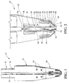
FIG. 1 is a perspective view of an illustrative embodiment of a clamp arm or gripper with gripping surfaces which can conform to the object being manipulated. -
FIG. 2 is an enlarged perspective view of the gripper head of the clamp arm ofFIG. 1 . -
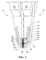
FIG. 3 is an enlarged perspective view of a first alternative gripper head. -
FIG. 4 is an enlarged perspective view of a second alternative gripper head. -
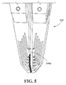
FIG. 5 is an enlarged perspective view of a third alternative gripper head. -
FIG. 6 is an enlarged perspective view of a fourth alternative gripper head. -
FIG. 7 is an enlarged perspective view of a fifth alternative gripper head. -
FIG. 8 is a perspective view of an illustrative embodiment of an alternate clamp arm or gripper with gripping surfaces as shown inFIG. 7 . - The description of illustrative embodiments according to principles of the present invention is intended to be read in connection with the accompanying drawings, which are to be considered part of the entire written description. In the description of embodiments of the invention disclosed herein, any reference to direction or orientation is merely intended for convenience of description and is not intended in any way to limit the scope of the present invention. Relative terms such as "lower," "upper," "horizontal," "vertical," "above," "below," "up," "down," "top" and "bottom" as well as derivative thereof (e.g., "horizontally," "downwardly," "upwardly," etc.) should be construed to refer to the orientation as then described or as shown in the drawing under discussion. These relative terms are for convenience of description only and do not require that the apparatus be constructed or operated in a particular orientation unless explicitly indicated as such. Terms such as "attached," "affixed," "connected," "coupled," "interconnected," and similar refer to a relationship wherein structures are secured or attached to one another either directly or indirectly through intervening structures, as well as both movable or rigid attachments or relationships, unless expressly described otherwise. Moreover, the features and benefits of the invention are illustrated by reference to the preferred embodiments. Accordingly, the invention expressly should not be limited to such preferred embodiments illustrating some possible non-limiting combination of features that may exist alone or in other combinations of features, the scope of the invention being defined by the claims appended hereto.
- Referring to
FIGS. 1 and 2 , a clamp arm orgripper 10 is shown. Theclamp arm 10 may be used with automated equipment, such as, but not limited to, robotic equipment. Theclamp arm 10 can pick up or manipulate a large variety of objects or parts of different shapes (not shown). The clamp arm orgripper 10 can conform to the object or part being picked up or engaged. In the illustrative embodiments shown, gripper surfaces conform to the object or part based upon the shape of the object or part and/or the force required to manipulate the object or part, as will be more fully described. - The
clamp arms 10 may be mounted to known apparatus for performing automated functions. Such apparatus may include a motor, a clamp arm mounting members and linkages to connect the motor to the clamp arm mounting members. As such apparatuses are known, a further explanation of such apparatuses will not be included. - In the exemplary embodiment shown, each
clamp arm 10 has amounting section 12, anextension section 14 and agripper section 16. In the embodiment shown, themounting section 12 hasopenings 18 which extend therethrough. Theopenings 18 are configured to receive mounting hardware (not shown) therein to mount themounting section 12 to the clamp arm mounting members. However, other configurations of themounting section 12 can be used without departing from the scope of the invention. - In the illustrative embodiment, the
extension section 14 is connected to thegripper section 16 by means of mountinghardware 20. However, in other embodiments, thegripper section 16 may be fastened to theextension section 14 by other means or alternatively, thegripper section 16 may be made in one piece with theextension section 14. - As best shown in
FIG. 2 , thegripper section 16 includes a first beam member orspring arm 30 and a second beam member orspring arm 32 which extends from abase 22 of thegripper section 16. Thefirst spring arm 30 has a fixedend 34. Afirst section 36 extends from the fixedend 34. Abend 38 is provided between thefirst section 36 and asecond section 40. Afree end 42 is provided at the end of thesecond section 40 which is remote from thebend 38.Gripper surfaces 44 are provided proximate to and/or adjacent to thefree end 42. Apositioning member 46 is provided proximate thefree end 42. Thepositioning member 46 is provided inrecess 48 of thegripper section 16. Thesecond section 40 has anengagement portion 50 which cooperates with asurface 52 ofgripper section 16. - The
second spring arm 32 has a fixedend 54. Afirst section 56 extends from the fixedend 54. Abend 58 is provided between thefirst section 56 and asecond section 60. Afree end 62 is provided at the end of thesecond section 60 which is remote from thebend 58.Gripper surfaces 64 are provided proximate to and/or adjacent to thefree end 62. Apositioning member 66 is provided proximate thefree end 62. Thepositioning member 66 is provided in therecess 48 of thegripper section 16. Thesecond section 60 has anengagement portion 70 which cooperates with asurface 72 ofgripper section 16. - Each
gripper surface projections 74 provided thereon. The grooves, serrations orprojections 74 are provided to facilitate the gripping of the object/part by the gripper surfaces 44, 64. - A
stop surface 76 is provided on thegripper section 16. The stop surfaces 76 ofadjacent gripper sections 16 cooperate with each other to prevent thegripper sections 16 and theclamp arms 10 from moving too closely together, thereby preventing the overstress of thefirst spring arms 30. - In operation, a pair of
clamp arms 10 are moved together to manipulate or engage an object/part. As theclamp arms 10 are moved together, the gripper surfaces 44, 64 engage the object/part. As the gripper surfaces 44, 64 are attached to the first andsecond spring arms first spring arms 30 move independently of the gripper surfaces 46 and thesecond spring arms 32. This allows each of the gripper surfaces 46, 66 to move, pivot or rotate to better accommodate or conform to the shape of the object/part to be manipulated. - As the gripper surfaces 44, 64 encounter the object/part, the gripper surfaces 44, 64 can move, pivot or rotate about positioning
members positioning members recesses 48. This allows the respective adjacent gripper surfaces 44, 64 to move, pivot or rotate while being maintained in position relative to each other, thereby preventing the object/part from being inadvertently moved between the gripper surfaces 44, 64. - As the gripper surfaces 44, 64 are continued to be moved together, the
portion 50 of thesecond section 40 of thefirst arm 30 engages thesurface 52 ofgripper section 16 to provide increased grip force while controlling the over deflection of thefirst arm 30. In addition, theportion 70 of thesecond section 60 of thesecond arm 32 engages thesurface 72 ofgripper section 16 to provide increased grip force while controlling the over deflection of thesecond arm 32. - In the embodiment shown in
FIG. 1 , the gripper surfaces 44, 64 are angled relative to each other. This allows the gripper surfaces 44, 64 to influence the movement of the object/part to the center of the gripper surfaces 44, 64, thereby providing a more stable grip of the object/part. However, the gripper surfaces 44, 64 may have a parallel configuration without departing from the scope of the invention. - The
gripper section 16 may be formed from any material having the appropriate strength, resilient (good spring properties), and weight (light weight) characteristics. Such material includes, but is not limited to, titanium, spring steel, stainless steel, polymers and glass filled plastic. The first andsecond spring arms second spring arms - Referring to
FIG. 3 , an alternate exemplary embodiment of agripper section 316 is shown. Thegripper section 316 includes a first beam member orspring arm 330 and a second beam member orspring arm 332. Thefirst spring arm 330 has a fixedend 334. Afirst section 336 extends from thefixed end 334. Abend 338 is provided between thefirst section 336 and asecond section 340. Afree end 342 is provided at the end of thesecond section 340 which is remote from thebend 338. Gripper surfaces 344 are provided proximate to and/or adjacent to thefree end 342. A positioning member 346 is provided proximate thefree end 342. The positioning member 346 is provided proximate asurface 348 of thegripper section 316. - The
second spring arm 332 has a fixedend 354. Afirst section 356 extends from thefixed end 354. Abend 358 is provided between thefirst section 356 and asecond section 360. Afree end 362 is provided at the end of thesecond section 360 which is remote from thebend 358. Gripper surfaces 364 are provided proximate to and/or adjacent to thefree end 362. - Each
gripper surface projections 374 provided thereon. The grooves, serrations orprojections 374 are provided to facilitate the gripping of the object/part by the gripper surfaces 344, 364. - In operation, a pair of clamp arms are moved together to manipulate or engage an object/part. As the clamp arms are moved together, the gripper surfaces 344, 364 engage the object/part. As the gripper surfaces 344, 364 are attached to the first and
second spring arms first spring arms 330 move independently of the gripper surfaces 344 and thesecond spring arms 332. This allows each of the gripper surfaces 344, 364 to move, pivot or rotate to better accommodate or conform to the shape of the object/part to be manipulated. - As the gripper surfaces 344, 364 are continued to be moved together, a
portion 350 of thefirst section 336 or thebend 338 of thefirst arm 330 engages aportion 370 of thefirst section 356 or bend 358 of thesecond arm 332 to provide increased grip force while controlling the over deflection of thefirst arm 330. This allows thefirst arm 330 to act in a serial progression with thesecond arm 332. The amount of force provided by thefirst arm 330 andsecond arm 332 can be determined or adjusted by changing the width, length or configuration of the spring arms. - In the embodiment shown in
FIG. 3 , the gripper surfaces 344, 364 are angled relative to each other. This allows the gripper surfaces 344, 364 to influence the movement of the object/part to the center of the gripper surfaces 344, 364, thereby providing a more stable grip of the object/part. The angled gripper surfaces 344, 334 also facilitate the holding and manipulation of objects/parts with round sections. However, the gripper surfaces 344, 364 may have a parallel configuration without departing from the scope of the invention. - The
gripper section 316 may be formed from any material having the appropriate strength, resilient (good spring properties) and weight (light weight) characteristics. Such material includes, but is not limited to, titanium, spring steel, stainless steel, polymers and glass filled plastic. The first andsecond spring arms second spring arms - Referring to
FIG. 4 , an alternate exemplary embodiment of agripper section 416 is shown. Thegripper section 416 includes a first beam member orspring arm 429, a second beam member orspring arm 430, a third beam member orspring arm 431, a fourth beam member orspring arm 432 and a fifth beam member orspring arm 433. While five spring arms are provided on eachgripper section 416, other numbers of spring arms may be provided without departing from the scope of the invention. Eachspring arm end 434a - 434e.First sections 436a - 436e extend from the fixed ends 434a - 434e. Bends 438a - 438e are provided between thefirst sections 436a - 436e andsecond sections 440a - 440e. Free ends 442a - 442e are provided at the end of thesecond sections 440a - 440e which are remote from the bends 438a - 438e. Gripper surfaces 444a - 444e are provided proximate to and/or adjacent to the free end 442a - 442e. - Each
gripper surface 444a - 444e may have grooves, serrations orprojections 474 provided thereon. The grooves, serrations orprojections 474 are provided to facilitate the gripping of the object/part by thegripper surfaces 444a - 444e. - In operation, a pair of clamp arms are moved together to manipulate or engage an object/part. As the clamp arms are moved together, the
gripper surfaces 444a - 444e of each clamp engage the object/part. As thegripper surfaces 444a - 444e are attached to the spring arms 429 - 433 respectively, thegripper surfaces 444a - 444e and their respective spring arms 429 - 433 move independently of theother gripper surfaces 444a - 444e and their respective spring arms 429 - 433. This allows each of thegripper surfaces 444a - 444e to move, pivot or rotate to better accommodate or conform to the shape of the object/part to be manipulated. - As the
gripper surfaces 444a - 444e are continued to be moved together, aportion 450a - 450d of thefirst sections 436a - 436d or the bends 438a - 438d of the arms 429 - 432 engagerespective portions 470b - 470e of the first section 436b - 436e or bends 438b - 438e of the second arms 430 - 433 to provide increased grip force while controlling the over deflection of thefirst arm 430. This allows thefirst arm 430 to act in a serial progression with the arms 429 - 432. The amount of force provided by the arms 429 - 433 can be determined or adjusted by changing the width, length or configuration of the spring arms. - In the embodiment shown in
FIG. 4 , thegripper surfaces gripper surfaces gripper surfaces - The
gripper section 416 may be formed from any material having the appropriate strength, resilient (good spring properties) and weight (light weight) characteristics. Such material includes, but is not limited to, titanium, spring steel, stainless steel, polymers and glass filled plastic. The spring arms 429 - 433 may be formed be removing material using machining, wire electrical discharge machining (EDM), lasers, water jets or other known methods. Alternatively, the spring arms 429 - 433 may be formed by stamping, extrusion molding or other known methods. - Referring to
FIG. 5 , an alternate exemplary embodiment of agripper section 516 is shown.Gripper section 516 has many similarities togripper section 416. However, thegripper surface 544a has a modified configuration as compared to gripper surface and 444a. - Referring to
FIG. 6 , an alternate exemplary embodiment of agripper section 616 is shown. Thegripper section 616 includes a first beam member orspring arm 627, a second beam member orspring arm 628, a third beam member orspring arm 629, a fourth beam member orspring arm 630, a fifth beam member orspring arm 631, a sixth beam member orspring arm 632 and a seventh beam member orspring arm 633. While seven spring arms are provided on eachgripper section 616, other numbers of spring arms may be provided without departing from the scope of the invention. Eachspring arm spring arms 429 through 433 and the operation thereof. - In the embodiment shown in
FIG. 6 , thegripper surfaces 644a - 644g are essentially in-line and parallel relative to each other. However, some or all of thegripper surfaces 644a - 644g may have angled surfaces without departing from the scope of the invention. - Referring to
FIGS. 7 and 8 , an alternate exemplary embodiment of agripper section 716 is shown. Thegripper section 716 has a thinner profile than thegripper section 616 to allow thegripper section 716 to have a longer reach. Thegripper section 716 includes a first beam member orspring arm 727, a second beam member orspring arm 728, a third beam member orspring arm 729, a fourth beam member orspring arm 730, a fifth beam member orspring arm 731 and a sixth beam member orspring arm 732. While six spring arms are provided on eachgripper section 716, other numbers of spring arms may be provided without departing from the scope of the invention. Eachspring arm spring arms 429 through 433 and the operation thereof. - In the embodiment shown in
FIGS. 7 and 8 , thegripper surfaces 744a - 744f are essentially in-line and parallel relative to each other. However, some or all of thegripper surfaces 744a - 744f may have angled surfaces without departing from the scope of the invention. - In all of the embodiments the gripper surfaces move, pivot or rotate based on the shape of the part or object to enable better gripping of the part or object. The fingers/beams/spring arms of the gripper sections are also resiliently or elastically deformable to allow an appropriate force to be exerted by the gripper surfaces on the part or object. This allows the gripper surfaces, the fingers/beams/spring arms and the gripper sections to pick up or manipulate a variety of parts or objects of different shapes without the need to change the gripper sections.
- While the invention has been described with reference to a preferred embodiment, it will be understood by those skilled in the art that various changes may be made and equivalents may be substituted for elements thereof without departing from the scope of the invention of the invention as defined in the accompanying accompanying claims. In particular, it will be clear to those skilled in the art that the present invention may be embodied in other specific forms, structures, arrangements, proportions, sizes, and with other elements, materials and components, without departing from the scope of the claims. One skilled in the art will appreciate that the invention may be used with many modifications of structure, arrangement, proportions, sizes, materials and components and otherwise used in the practice of the invention, which are particularly adapted to specific environments and operative requirements without departing from the principles of the present invention. The presently disclosed embodiments are therefore to be considered in all respects as illustrative and not restrictive, the scope of the invention being defined by the appended claims, and not limited to the foregoing description or embodiments.
Claims (11)
- A gripper section (16) for use with a clamp arm (10) for use with automated machinery, the gripper section (16) comprising:a plurality of beam members (30, 32) which extend from a base (22), each beam member (30, 32) of the plurality of beam members (30, 32), having a fixed end (34, 54) and a free end (42, 62);a plurality of gripper surfaces (44, 64) proximate to the free ends (42, 62), each gripper surface (44, 64) attached to a respective beam member (30, 32) of the plurality of beam members (30, 32);each gripper surface (44, 64), of the plurality of gripper surfaces (44, 64) and its respective beam member (30, 32) are configured to move independently of the other gripper surface or gripper surfaces (44, 64) and beam member or beam members (30, 32);wherein the plurality of gripper surfaces (44, 64) and the plurality of beam members (30, 32) are configured to conform to the shape of an object/part to be manipulated by the gripper section (16).
- The gripper section (16) as recited in claim 1, wherein each beam member (30, 32) of the plurality of beam members (30, 32) has a first section (36, 56) which extends from the fixed end (34, 54), a second section (40, 60) which extends from the free end (42, 62) and a bend (38, 58) provided between the first section (36, 56) and the second section (40, 60).
- The gripper section (16) as recited in claim 1 or 2, wherein at least one beam member (30, 32) of the plurality of beam member (30, 32) has a positioning member (46, 66) to properly maintain at least one gripper surface (44, 64) of the plurality of gripper surfaces (44, 64) in position.
- The gripper section (16) as recited in claim 1, 2 or 3 wherein at least one gripper surface (44, 64) of the plurality of gripper surfaces (44, 64) is angled relative to another gripper surface (44, 64) of the plurality of gripper surfaces (44, 64) to influence movement of the object/part to a center of the plurality of gripper surfaces (44, 64).
- The gripper section (416) as recited in any preceding claim, wherein at least one gripper surface (444b, 444c, 444d) of the plurality of gripper surfaces (444a - 444e) is parallel relative to another gripper surface (444b, 444c, 444d) of the plurality of gripper surfaces (444a - 444e).
- The gripper section (416) as recited in any preceding claim, wherein a first gripper surface (444a) of the plurality of gripper surfaces (444a - 444e) is angled relative to second gripper surface (444b) of the plurality of gripper surfaces (444a - 444e) and a third gripper (444c) surface of the plurality of gripper surfaces (444a - 444e) is parallel relative to the second gripper surface (444b) of the plurality of gripper surfaces (444a - 444e).
- The gripper section (16) as recited in any preceding claim, wherein engagement portions (50, 70) are provided on the plurality of beam members (30, 32) wherein as the plurality of gripper surfaces (44, 64) conform to the shape of an object/part to be manipulated by the gripper section (16), the engagement portions (50, 70) of the plurality of beam members (30, 32) engage surfaces of the base (22) or portions of other of the plurality of beam members (30, 32) to provide increased force to the object/part.
- The gripper section (16) as recited in any preceding claim, wherein the plurality of gripper surfaces (44, 64) have grooves, serrations, or projections (74) provided thereon to facilitate the gripping of the object/part.
- The gripper section (16) as recited in any preceding claim, wherein a stop surface (76) is provided to prevent adjacent gripper sections (16) from moving too closely together.
- The gripper section (16) as recited in any preceding claim, wherein the plurality of gripper surfaces (44, 64) move, pivot or rotate relative to the base (22).
- The gripper section (16) as recited in any preceding claim, wherein the plurality of gripper surfaces (44, 64) move, rotate or pivot independently from each other.
Applications Claiming Priority (1)
| Application Number | Priority Date | Filing Date | Title |
|---|---|---|---|
| US14/839,101 US9505135B1 (en) | 2015-08-28 | 2015-08-28 | Gripper with conformal spring fingers |
Publications (1)
| Publication Number | Publication Date |
|---|---|
| EP3147088A1 true EP3147088A1 (en) | 2017-03-29 |
Family
ID=56799295
Family Applications (1)
| Application Number | Title | Priority Date | Filing Date |
|---|---|---|---|
| EP16185111.8A Withdrawn EP3147088A1 (en) | 2015-08-28 | 2016-08-22 | Gripper with conformal spring fingers |
Country Status (4)
| Country | Link |
|---|---|
| US (1) | US9505135B1 (en) |
| EP (1) | EP3147088A1 (en) |
| JP (1) | JP2017042907A (en) |
| CN (1) | CN106476031A (en) |
Cited By (1)
| Publication number | Priority date | Publication date | Assignee | Title |
|---|---|---|---|---|
| CN113500620A (en) * | 2021-07-16 | 2021-10-15 | 青岛海信宽带多媒体技术有限公司 | Electric clamping jaw mechanism |
Families Citing this family (16)
| Publication number | Priority date | Publication date | Assignee | Title |
|---|---|---|---|---|
| DE102015114556A1 (en) * | 2015-09-01 | 2017-03-02 | Röhm Gmbh | Gripper and method for making a gripper |
| DE102015114580A1 (en) * | 2015-09-01 | 2017-03-02 | Röhm Gmbh | Gripper and method for making a gripper |
| US9914214B1 (en) * | 2016-02-22 | 2018-03-13 | X Development Llc | Preshaping for underactuated fingers |
| FI128465B (en) * | 2017-09-05 | 2020-05-29 | Cross Wrap Oy | A gripping device for gripping a binding material from an object |
| US10759062B2 (en) * | 2017-12-08 | 2020-09-01 | Dishcraft Robotics, Inc. | Article of dishware gripping systems |
| US11014226B2 (en) | 2018-10-26 | 2021-05-25 | Toyota Motor Engineering & Manufacturing North America, Inc. | Automated pick and place apparatuses with object alignment systems |
| JP6991395B2 (en) * | 2018-10-30 | 2022-01-12 | シーメンス アクチエンゲゼルシヤフト | Gripping fingers and adaptive gripping devices with curved spacer members |
| CN109807917B (en) * | 2019-03-15 | 2021-06-15 | 浙江大学 | A coupled manipulator for adaptive grasping of objects |
| CN114466807A (en) * | 2019-08-26 | 2022-05-10 | 简·探针公司 | Container transport carrier |
| IT202000005257A1 (en) * | 2020-03-11 | 2021-09-11 | Aea Srl | GRIPPING DEVICE |
| CN111329582B (en) | 2020-03-17 | 2021-04-13 | 上海奥朋医疗科技有限公司 | Elastic gathering self-centering flat clamping mechanical finger for blood vessel intervention |
| EP3885844A1 (en) * | 2020-03-27 | 2021-09-29 | Nivarox-FAR S.A. | Clamp for a timepiece setting machine |
| CN112171704A (en) * | 2020-08-25 | 2021-01-05 | 武汉船用机械有限责任公司 | Clamping device |
| CN113370258B (en) * | 2021-07-13 | 2022-04-15 | 太原理工大学 | Rotary clamping jaw |
| CN113442158B (en) * | 2021-07-28 | 2022-06-03 | 太原理工大学 | Self-adaptive bidirectional variable-rigidity clamping jaw |
| US12480288B2 (en) * | 2022-09-07 | 2025-11-25 | Esco Group Llc | Handling system for ground-engaging wear parts secured to earth working equipment |
Citations (8)
| Publication number | Priority date | Publication date | Assignee | Title |
|---|---|---|---|---|
| JPS61189836A (en) * | 1985-02-18 | 1986-08-23 | Ishikawajima Harima Heavy Ind Co Ltd | Work handling device of manipulator for forcing |
| US4632444A (en) * | 1985-05-03 | 1986-12-30 | Rca Corporation | Robot hand |
| JPH04217410A (en) * | 1990-12-14 | 1992-08-07 | Olympus Optical Co Ltd | Lens chucking device |
| JPH05169387A (en) * | 1991-12-17 | 1993-07-09 | Fujitsu Ltd | Robot hand |
| JPH06190764A (en) * | 1992-12-25 | 1994-07-12 | Hitachi Ltd | Gripping mechanism |
| DE202012012083U1 (en) * | 2012-12-18 | 2013-01-16 | Fipa Gmbh | Gripper, in particular pneumatically operated gripper |
| JP2013123769A (en) * | 2011-12-14 | 2013-06-24 | Seiko Epson Corp | Holding device and robot |
| US20150028613A1 (en) * | 2013-07-26 | 2015-01-29 | Fanuc Corporation | Robot gripping device |
Family Cites Families (26)
| Publication number | Priority date | Publication date | Assignee | Title |
|---|---|---|---|---|
| US3343864A (en) * | 1965-10-07 | 1967-09-26 | James I Baer | Material handling apparatus and the like |
| US4600357A (en) | 1984-02-21 | 1986-07-15 | Heath Company | Gripper force sensor/controller for robotic arm |
| US4850631A (en) * | 1987-05-22 | 1989-07-25 | Martin Dotsko | Article manipulator |
| US5046773A (en) * | 1990-01-02 | 1991-09-10 | Hewlett-Packard Company | Micro-gripper assembly |
| US5356187A (en) * | 1993-06-21 | 1994-10-18 | The United States Of America As Represented By The Secretary Of The Navy | Recovery and deployment device |
| US5762390A (en) | 1996-07-16 | 1998-06-09 | Universite Laval | Underactuated mechanical finger with return actuation |
| CN100372660C (en) * | 2002-06-24 | 2008-03-05 | 松下电器产业株式会社 | Multi-joint drive mechanism, manufacturing method thereof, handle and robot using same |
| TW566423U (en) * | 2003-04-23 | 2003-12-11 | Ind Tech Res Inst | Structure for miniature gripping clip |
| DE102005046160C5 (en) | 2005-09-27 | 2008-12-24 | Fraunhofer-Gesellschaft zur Förderung der angewandten Forschung e.V. | Robotic gripper and method for its manufacture |
| US20080025822A1 (en) * | 2006-04-17 | 2008-01-31 | Sangbae Kim | Device and method for handling an object of interest using a directional adhesive structure |
| US8414043B2 (en) | 2008-10-21 | 2013-04-09 | Foster-Miller, Inc. | End effector for mobile remotely controlled robot |
| US8141924B2 (en) | 2008-12-29 | 2012-03-27 | Foster-Miller, Inc. | Gripper system |
| DE102009021558B4 (en) * | 2009-05-14 | 2017-12-07 | Zahoransky Ag | tongs |
| US8382177B2 (en) | 2009-06-11 | 2013-02-26 | Re2, Inc. | Quick-change finger for robotic gripper |
| CA2765250C (en) | 2009-06-12 | 2017-12-05 | Kinova | Mechanical finger |
| CN101920499B (en) | 2009-06-12 | 2014-08-13 | 鸿富锦精密工业(深圳)有限公司 | Clamping device |
| US8550519B2 (en) * | 2009-10-17 | 2013-10-08 | GM Global Technology Operations LLC | Mechanical grippers utilizing active material activation |
| JP2011131341A (en) | 2009-12-25 | 2011-07-07 | Sony Corp | Gripping device |
| US8936289B1 (en) | 2010-03-15 | 2015-01-20 | Telefactor Robotics LLC | Robotic finger assemblies |
| FR2965501B1 (en) * | 2010-09-30 | 2013-08-02 | Commissariat Energie Atomique | FLEXIBLE MECATRONIC STRUCTURE FOR A KINEMATIC ASSEMBLY, SURGICAL DEVICE, AND ARTIFICIAL MEMBER USING THE STRUCTURE |
| WO2012129288A2 (en) | 2011-03-21 | 2012-09-27 | Re2, Inc. | Robotic hand with conformal finger |
| US8534729B2 (en) | 2011-08-04 | 2013-09-17 | Harris Corporation | High-force robotic gripper |
| CN102416624A (en) * | 2011-12-15 | 2012-04-18 | 余胜东 | Flexible adaptive under-actuated robot paw |
| CN103921160B (en) * | 2014-04-01 | 2016-05-04 | 广东鼎泰机器人科技有限公司 | For picking and placeing the elastic mechanical jaw of the micro-brill of PCB |
| CN203919072U (en) * | 2014-06-06 | 2014-11-05 | 余胜东 | Band is from the enhancement mode manipulator of cooling system and elasticity paw function |
| CN106346510B (en) * | 2016-10-11 | 2018-08-14 | 佛山科学技术学院 | A kind of finger clamper of submissive type three with tactilely-perceptible function |
-
2015
- 2015-08-28 US US14/839,101 patent/US9505135B1/en active Active
-
2016
- 2016-08-22 EP EP16185111.8A patent/EP3147088A1/en not_active Withdrawn
- 2016-08-23 JP JP2016162325A patent/JP2017042907A/en active Pending
- 2016-08-24 CN CN201610719553.1A patent/CN106476031A/en active Pending
Patent Citations (8)
| Publication number | Priority date | Publication date | Assignee | Title |
|---|---|---|---|---|
| JPS61189836A (en) * | 1985-02-18 | 1986-08-23 | Ishikawajima Harima Heavy Ind Co Ltd | Work handling device of manipulator for forcing |
| US4632444A (en) * | 1985-05-03 | 1986-12-30 | Rca Corporation | Robot hand |
| JPH04217410A (en) * | 1990-12-14 | 1992-08-07 | Olympus Optical Co Ltd | Lens chucking device |
| JPH05169387A (en) * | 1991-12-17 | 1993-07-09 | Fujitsu Ltd | Robot hand |
| JPH06190764A (en) * | 1992-12-25 | 1994-07-12 | Hitachi Ltd | Gripping mechanism |
| JP2013123769A (en) * | 2011-12-14 | 2013-06-24 | Seiko Epson Corp | Holding device and robot |
| DE202012012083U1 (en) * | 2012-12-18 | 2013-01-16 | Fipa Gmbh | Gripper, in particular pneumatically operated gripper |
| US20150028613A1 (en) * | 2013-07-26 | 2015-01-29 | Fanuc Corporation | Robot gripping device |
Cited By (1)
| Publication number | Priority date | Publication date | Assignee | Title |
|---|---|---|---|---|
| CN113500620A (en) * | 2021-07-16 | 2021-10-15 | 青岛海信宽带多媒体技术有限公司 | Electric clamping jaw mechanism |
Also Published As
| Publication number | Publication date |
|---|---|
| JP2017042907A (en) | 2017-03-02 |
| US9505135B1 (en) | 2016-11-29 |
| CN106476031A (en) | 2017-03-08 |
Similar Documents
| Publication | Publication Date | Title |
|---|---|---|
| US9505135B1 (en) | Gripper with conformal spring fingers | |
| US11260540B2 (en) | Automatic pick-up equipment | |
| US10112309B2 (en) | Gripping device attached to robot | |
| CN114559428B (en) | System and method for providing a dynamic robot control system | |
| US9882333B2 (en) | Gripping and assembling device for flexible object | |
| EP2193888A3 (en) | Multiple arm robot arrangement | |
| US9540186B2 (en) | Conveyor system and conveyance method | |
| US8596699B2 (en) | Gripping device | |
| CN100579733C (en) | Operators and Handling Robots | |
| CN214641305U (en) | Quick locking device of intelligent mechanical welding hand | |
| EP1714750A1 (en) | Robot hand comprising gripping claws | |
| CN112243601B (en) | Wire insertion device and wire insertion method | |
| US11400603B2 (en) | End effector device and robotic device | |
| EP4098411B1 (en) | A gripper and a method of using a robot with the gripper | |
| KR101382666B1 (en) | Parallel manipulator | |
| CN105692191A (en) | Material grabbing mechanical arm | |
| KR102350801B1 (en) | Gripper for gripping forged fittings irregular shapes | |
| EP3969234A1 (en) | Tool changing system, industrial robot and method of handling tool by industrial robot | |
| WO2019046898A1 (en) | Translational parallel manipulator | |
| CN108453783B (en) | Self-adjusting assembly manipulator | |
| JP2018144216A (en) | Robot hand | |
| JP6982922B1 (en) | Gripping device | |
| EP3560654B1 (en) | Machine for machining workpieces | |
| CN108453775B (en) | Assembly manipulator capable of being automatically and finely adjusted | |
| KR20200020054A (en) | Handler for robot and robot having the same |
Legal Events
| Date | Code | Title | Description |
|---|---|---|---|
| PUAI | Public reference made under article 153(3) epc to a published international application that has entered the european phase |
Free format text: ORIGINAL CODE: 0009012 |
|
| STAA | Information on the status of an ep patent application or granted ep patent |
Free format text: STATUS: THE APPLICATION HAS BEEN PUBLISHED |
|
| AK | Designated contracting states |
Kind code of ref document: A1 Designated state(s): AL AT BE BG CH CY CZ DE DK EE ES FI FR GB GR HR HU IE IS IT LI LT LU LV MC MK MT NL NO PL PT RO RS SE SI SK SM TR |
|
| AX | Request for extension of the european patent |
Extension state: BA ME |
|
| STAA | Information on the status of an ep patent application or granted ep patent |
Free format text: STATUS: REQUEST FOR EXAMINATION WAS MADE |
|
| 17P | Request for examination filed |
Effective date: 20171130 |
|
| RBV | Designated contracting states (corrected) |
Designated state(s): AL AT BE BG CH CY CZ DE DK EE ES FI FR GB GR HR HU IE IS IT LI LT LU LV MC MK MT NL NO PL PT RO RS SE SI SK SM TR |
|
| STAA | Information on the status of an ep patent application or granted ep patent |
Free format text: STATUS: EXAMINATION IS IN PROGRESS |
|
| 17Q | First examination report despatched |
Effective date: 20210521 |
|
| STAA | Information on the status of an ep patent application or granted ep patent |
Free format text: STATUS: THE APPLICATION HAS BEEN WITHDRAWN |
|
| 18W | Application withdrawn |
Effective date: 20210804 |