EP3147048A1 - Method and device for implementing laser shock peening (lsp) or warm laser shock peening (wlsp) during selective laser melting (slm) - Google Patents
Method and device for implementing laser shock peening (lsp) or warm laser shock peening (wlsp) during selective laser melting (slm) Download PDFInfo
- Publication number
- EP3147048A1 EP3147048A1 EP16191015.3A EP16191015A EP3147048A1 EP 3147048 A1 EP3147048 A1 EP 3147048A1 EP 16191015 A EP16191015 A EP 16191015A EP 3147048 A1 EP3147048 A1 EP 3147048A1
- Authority
- EP
- European Patent Office
- Prior art keywords
- laser
- layer
- lsp
- wlsp
- slm
- Prior art date
- Legal status (The legal status is an assumption and is not a legal conclusion. Google has not performed a legal analysis and makes no representation as to the accuracy of the status listed.)
- Granted
Links
Images


Classifications
-
- B—PERFORMING OPERATIONS; TRANSPORTING
- B29—WORKING OF PLASTICS; WORKING OF SUBSTANCES IN A PLASTIC STATE IN GENERAL
- B29C—SHAPING OR JOINING OF PLASTICS; SHAPING OF MATERIAL IN A PLASTIC STATE, NOT OTHERWISE PROVIDED FOR; AFTER-TREATMENT OF THE SHAPED PRODUCTS, e.g. REPAIRING
- B29C64/00—Additive manufacturing, i.e. manufacturing of three-dimensional [3D] objects by additive deposition, additive agglomeration or additive layering, e.g. by 3D printing, stereolithography or selective laser sintering
- B29C64/10—Processes of additive manufacturing
- B29C64/141—Processes of additive manufacturing using only solid materials
- B29C64/153—Processes of additive manufacturing using only solid materials using layers of powder being selectively joined, e.g. by selective laser sintering or melting
-
- B—PERFORMING OPERATIONS; TRANSPORTING
- B22—CASTING; POWDER METALLURGY
- B22F—WORKING METALLIC POWDER; MANUFACTURE OF ARTICLES FROM METALLIC POWDER; MAKING METALLIC POWDER; APPARATUS OR DEVICES SPECIALLY ADAPTED FOR METALLIC POWDER
- B22F10/00—Additive manufacturing of workpieces or articles from metallic powder
- B22F10/20—Direct sintering or melting
- B22F10/28—Powder bed fusion, e.g. selective laser melting [SLM] or electron beam melting [EBM]
-
- B—PERFORMING OPERATIONS; TRANSPORTING
- B22—CASTING; POWDER METALLURGY
- B22F—WORKING METALLIC POWDER; MANUFACTURE OF ARTICLES FROM METALLIC POWDER; MAKING METALLIC POWDER; APPARATUS OR DEVICES SPECIALLY ADAPTED FOR METALLIC POWDER
- B22F10/00—Additive manufacturing of workpieces or articles from metallic powder
- B22F10/30—Process control
- B22F10/38—Process control to achieve specific product aspects, e.g. surface smoothness, density, porosity or hollow structures
-
- B—PERFORMING OPERATIONS; TRANSPORTING
- B22—CASTING; POWDER METALLURGY
- B22F—WORKING METALLIC POWDER; MANUFACTURE OF ARTICLES FROM METALLIC POWDER; MAKING METALLIC POWDER; APPARATUS OR DEVICES SPECIALLY ADAPTED FOR METALLIC POWDER
- B22F10/00—Additive manufacturing of workpieces or articles from metallic powder
- B22F10/50—Treatment of workpieces or articles during build-up, e.g. treatments applied to fused layers during build-up
-
- B—PERFORMING OPERATIONS; TRANSPORTING
- B22—CASTING; POWDER METALLURGY
- B22F—WORKING METALLIC POWDER; MANUFACTURE OF ARTICLES FROM METALLIC POWDER; MAKING METALLIC POWDER; APPARATUS OR DEVICES SPECIALLY ADAPTED FOR METALLIC POWDER
- B22F12/00—Apparatus or devices specially adapted for additive manufacturing; Auxiliary means for additive manufacturing; Combinations of additive manufacturing apparatus or devices with other processing apparatus or devices
- B22F12/40—Radiation means
- B22F12/44—Radiation means characterised by the configuration of the radiation means
- B22F12/45—Two or more
-
- B—PERFORMING OPERATIONS; TRANSPORTING
- B23—MACHINE TOOLS; METAL-WORKING NOT OTHERWISE PROVIDED FOR
- B23K—SOLDERING OR UNSOLDERING; WELDING; CLADDING OR PLATING BY SOLDERING OR WELDING; CUTTING BY APPLYING HEAT LOCALLY, e.g. FLAME CUTTING; WORKING BY LASER BEAM
- B23K26/00—Working by laser beam, e.g. welding, cutting or boring
- B23K26/009—Working by laser beam, e.g. welding, cutting or boring using a non-absorbing, e.g. transparent, reflective or refractive, layer on the workpiece
-
- B—PERFORMING OPERATIONS; TRANSPORTING
- B23—MACHINE TOOLS; METAL-WORKING NOT OTHERWISE PROVIDED FOR
- B23K—SOLDERING OR UNSOLDERING; WELDING; CLADDING OR PLATING BY SOLDERING OR WELDING; CUTTING BY APPLYING HEAT LOCALLY, e.g. FLAME CUTTING; WORKING BY LASER BEAM
- B23K26/00—Working by laser beam, e.g. welding, cutting or boring
- B23K26/34—Laser welding for purposes other than joining
- B23K26/342—Build-up welding
-
- B—PERFORMING OPERATIONS; TRANSPORTING
- B23—MACHINE TOOLS; METAL-WORKING NOT OTHERWISE PROVIDED FOR
- B23K—SOLDERING OR UNSOLDERING; WELDING; CLADDING OR PLATING BY SOLDERING OR WELDING; CUTTING BY APPLYING HEAT LOCALLY, e.g. FLAME CUTTING; WORKING BY LASER BEAM
- B23K26/00—Working by laser beam, e.g. welding, cutting or boring
- B23K26/352—Working by laser beam, e.g. welding, cutting or boring for surface treatment
- B23K26/356—Working by laser beam, e.g. welding, cutting or boring for surface treatment by shock processing
-
- B—PERFORMING OPERATIONS; TRANSPORTING
- B29—WORKING OF PLASTICS; WORKING OF SUBSTANCES IN A PLASTIC STATE IN GENERAL
- B29C—SHAPING OR JOINING OF PLASTICS; SHAPING OF MATERIAL IN A PLASTIC STATE, NOT OTHERWISE PROVIDED FOR; AFTER-TREATMENT OF THE SHAPED PRODUCTS, e.g. REPAIRING
- B29C64/00—Additive manufacturing, i.e. manufacturing of three-dimensional [3D] objects by additive deposition, additive agglomeration or additive layering, e.g. by 3D printing, stereolithography or selective laser sintering
- B29C64/10—Processes of additive manufacturing
- B29C64/188—Processes of additive manufacturing involving additional operations performed on the added layers, e.g. smoothing, grinding or thickness control
-
- B—PERFORMING OPERATIONS; TRANSPORTING
- B33—ADDITIVE MANUFACTURING TECHNOLOGY
- B33Y—ADDITIVE MANUFACTURING, i.e. MANUFACTURING OF THREE-DIMENSIONAL [3D] OBJECTS BY ADDITIVE DEPOSITION, ADDITIVE AGGLOMERATION OR ADDITIVE LAYERING, e.g. BY 3D PRINTING, STEREOLITHOGRAPHY OR SELECTIVE LASER SINTERING
- B33Y10/00—Processes of additive manufacturing
-
- B—PERFORMING OPERATIONS; TRANSPORTING
- B33—ADDITIVE MANUFACTURING TECHNOLOGY
- B33Y—ADDITIVE MANUFACTURING, i.e. MANUFACTURING OF THREE-DIMENSIONAL [3D] OBJECTS BY ADDITIVE DEPOSITION, ADDITIVE AGGLOMERATION OR ADDITIVE LAYERING, e.g. BY 3D PRINTING, STEREOLITHOGRAPHY OR SELECTIVE LASER SINTERING
- B33Y30/00—Apparatus for additive manufacturing; Details thereof or accessories therefor
-
- B—PERFORMING OPERATIONS; TRANSPORTING
- B33—ADDITIVE MANUFACTURING TECHNOLOGY
- B33Y—ADDITIVE MANUFACTURING, i.e. MANUFACTURING OF THREE-DIMENSIONAL [3D] OBJECTS BY ADDITIVE DEPOSITION, ADDITIVE AGGLOMERATION OR ADDITIVE LAYERING, e.g. BY 3D PRINTING, STEREOLITHOGRAPHY OR SELECTIVE LASER SINTERING
- B33Y40/00—Auxiliary operations or equipment, e.g. for material handling
-
- C—CHEMISTRY; METALLURGY
- C21—METALLURGY OF IRON
- C21D—MODIFYING THE PHYSICAL STRUCTURE OF FERROUS METALS; GENERAL DEVICES FOR HEAT TREATMENT OF FERROUS OR NON-FERROUS METALS OR ALLOYS; MAKING METAL MALLEABLE, e.g. BY DECARBURISATION OR TEMPERING
- C21D10/00—Modifying the physical properties by methods other than heat treatment or deformation
- C21D10/005—Modifying the physical properties by methods other than heat treatment or deformation by laser shock processing
-
- B—PERFORMING OPERATIONS; TRANSPORTING
- B22—CASTING; POWDER METALLURGY
- B22F—WORKING METALLIC POWDER; MANUFACTURE OF ARTICLES FROM METALLIC POWDER; MAKING METALLIC POWDER; APPARATUS OR DEVICES SPECIALLY ADAPTED FOR METALLIC POWDER
- B22F12/00—Apparatus or devices specially adapted for additive manufacturing; Auxiliary means for additive manufacturing; Combinations of additive manufacturing apparatus or devices with other processing apparatus or devices
- B22F12/10—Auxiliary heating means
-
- B—PERFORMING OPERATIONS; TRANSPORTING
- B22—CASTING; POWDER METALLURGY
- B22F—WORKING METALLIC POWDER; MANUFACTURE OF ARTICLES FROM METALLIC POWDER; MAKING METALLIC POWDER; APPARATUS OR DEVICES SPECIALLY ADAPTED FOR METALLIC POWDER
- B22F12/00—Apparatus or devices specially adapted for additive manufacturing; Auxiliary means for additive manufacturing; Combinations of additive manufacturing apparatus or devices with other processing apparatus or devices
- B22F12/40—Radiation means
- B22F12/41—Radiation means characterised by the type, e.g. laser or electron beam
- B22F12/43—Radiation means characterised by the type, e.g. laser or electron beam pulsed; frequency modulated
-
- B—PERFORMING OPERATIONS; TRANSPORTING
- B22—CASTING; POWDER METALLURGY
- B22F—WORKING METALLIC POWDER; MANUFACTURE OF ARTICLES FROM METALLIC POWDER; MAKING METALLIC POWDER; APPARATUS OR DEVICES SPECIALLY ADAPTED FOR METALLIC POWDER
- B22F12/00—Apparatus or devices specially adapted for additive manufacturing; Auxiliary means for additive manufacturing; Combinations of additive manufacturing apparatus or devices with other processing apparatus or devices
- B22F12/40—Radiation means
- B22F12/44—Radiation means characterised by the configuration of the radiation means
-
- C—CHEMISTRY; METALLURGY
- C21—METALLURGY OF IRON
- C21D—MODIFYING THE PHYSICAL STRUCTURE OF FERROUS METALS; GENERAL DEVICES FOR HEAT TREATMENT OF FERROUS OR NON-FERROUS METALS OR ALLOYS; MAKING METAL MALLEABLE, e.g. BY DECARBURISATION OR TEMPERING
- C21D1/00—General methods or devices for heat treatment, e.g. annealing, hardening, quenching or tempering
- C21D1/34—Methods of heating
- C21D1/38—Heating by cathodic discharges
-
- C—CHEMISTRY; METALLURGY
- C21—METALLURGY OF IRON
- C21D—MODIFYING THE PHYSICAL STRUCTURE OF FERROUS METALS; GENERAL DEVICES FOR HEAT TREATMENT OF FERROUS OR NON-FERROUS METALS OR ALLOYS; MAKING METAL MALLEABLE, e.g. BY DECARBURISATION OR TEMPERING
- C21D7/00—Modifying the physical properties of iron or steel by deformation
- C21D7/02—Modifying the physical properties of iron or steel by deformation by cold working
- C21D7/04—Modifying the physical properties of iron or steel by deformation by cold working of the surface
- C21D7/06—Modifying the physical properties of iron or steel by deformation by cold working of the surface by shot-peening or the like
-
- Y—GENERAL TAGGING OF NEW TECHNOLOGICAL DEVELOPMENTS; GENERAL TAGGING OF CROSS-SECTIONAL TECHNOLOGIES SPANNING OVER SEVERAL SECTIONS OF THE IPC; TECHNICAL SUBJECTS COVERED BY FORMER USPC CROSS-REFERENCE ART COLLECTIONS [XRACs] AND DIGESTS
- Y02—TECHNOLOGIES OR APPLICATIONS FOR MITIGATION OR ADAPTATION AGAINST CLIMATE CHANGE
- Y02P—CLIMATE CHANGE MITIGATION TECHNOLOGIES IN THE PRODUCTION OR PROCESSING OF GOODS
- Y02P10/00—Technologies related to metal processing
- Y02P10/25—Process efficiency
Definitions
- Selective Laser Melting SLM, fig 1
- DMLS Direct Metal Laser Sintering
- SLS Selective Laser Sintering
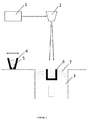
- Figure 1 illustrates a standard SLM process of the prior art.
- a powder bed is deposited on a substrate and selectively melted by a laser beam 1 piloted by a CAM system through a scanning head 2.
- the material gets consolidated, a building platform 3 is lowered for the value of the wanted layer height and a new powder layer is deposited by the deposition system 4 containing fresh powder 5.
- the operation sequence is repeated until completion of the part 6. At the end the unused powder 7 is removed and recycled.
- An aim of the present invention is thus to improve the known processes and devices.
- a further aim of the present invention is to propose a method using SLM allowing the construction of parts with improved characteristics.
- the invention concerns a method for manufacturing an object by selective laser melting (SLM) in which successive layers of material are added to form said object, wherein between the forming of said subsequent layers of the object, a plastic deformation and residual stresses are induced into the solidified material of at least one of said layers to improve the mechanical properties and the fatigue resistance of the object, wherein said plastic deformation and residual stresses are induced by a laser.
- SLM selective laser melting
- the plastic deformation and residual stresses are induced by a Laser Shock Peening (LSP) step or by a Warm Laser Shock Peening (WLSP) step.
- LSP Laser Shock Peening
- WLSP Warm Laser Shock Peening
- the layers or parts of a layer made with the SLM process are treated with multiple LSP or WLSP treatments.
- the lasers used for the SLM and the LSP or WLSP steps may be different lasers or the same laser, working in two different modes.
- a same scanning head or different scanning heads are used for the SLM and the LSP or WLSP steps.
- a horizontal 2-axes motion is used for the guiding of the laser used for the LSP or WLSP step instead of a scanning head.
- a mirror with a tilting motion can be used for guiding the laser used for LSP or WLSP.
- the treatment steps are followed by an optional selective (in situ) heat treatment.
- the selective heat treatment is made by a laser, an infrared lamp or a substrate preheating.
- a device is placed over at least a portion of said solidified material.
- This device comprises a confining and/or ablative layer.
- the confining layer is transparent to the laser beam and is applied to maximize the shock wave pressure and preventing it to rapidly expand from the surface of the material, thus increasing the depth of shockwave penetration.
- the ablative layer is used to avoid material ablation and is preferably made out of an opaque material.
- the invention concerns a system to carry out the method as described herein, said system may comprise a first laser, a scanning head, a powder deposition system containing fresh powder, a platform on which a part is built by a selective laser melting (SLM) process realized by the first laser.
- SLM selective laser melting
- the system also may comprise of a second laser, a confining layer transparent to laser and an ablative layer for applying a laser shock peening (LSP) step to the part being built.
- LSP laser shock peening
- the ablative layer is a liquid layer or a solid layer.
- system further comprises a heating unit to heat the part being built.
- the confining layer is made of two layers, where one can be treated as a consumable and is exchanged.
- the exchangeable layer is a top part of the ablative layer.
- the second confining layer is the top part of an ablative layer, and is brought on a roll.
- the first laser and the second laser are the same laser device working in two different modes, at the same or different wavelengths.
- a first idea of the present invention is to provide a device and a method for introducing Laser shock Peening (LSP) or Warm Laser Shock Peening (WLSP) during Selective Laser Melting (SLM) in order to change the residual stress field from a detrimental tensile residual stress (TRS) which is inherited from the SLM process, to a beneficial compressive residual stress (CRS) field in chosen critical zones, for example in the near surface region.
- LSP Laser shock Peening
- WLSP Warm Laser Shock Peening
- SLM Selective Laser Melting
- the objective of the present invention is therefore to provide an effective and economical method of improving mechanical properties, increasing fatigue life and part density and decreasing surface roughness of parts 6 built by SLM during the building process itself. These improvements are made throughout the volume of the part 6, by using Laser Shock Peening or Warm Laser Shock Peening during the SLM process. This gives the advantage of changing the residual stress field from the detrimental TRS to a beneficial CRS, introducing these changes and hardening the material in much larger depths compared to LSP/WLSP as a surface treatment. It also gives a possibility to selectively treat critical sections of the produced part. This is very important for parts 6 that have internal voids, lattice structure or some other complex geometries, which are very often produced by the SLM process.
- the said objective is achieved by providing a method and a device for introducing Laser Shock Peening (LSP) or Warm Laser Shock Peening (WLSP) during the Selective Laser Melting (SLM) process.
- LSP Laser Shock Peening
- WLSP Warm Laser Shock Peening
- SLM Selective Laser Melting
- LSP Laser Shock Peening
- Laser Shock Processing also known as Laser Shock Processing, Laser Shot Peening or Laser Peening
- Laser Peening is a surface treatment process used to improve surface integrity which significantly impacts component performance and increases its fatigue resistance and this principle is used in another embodiment of the present invention.
- a pulsed laser is used to produce shock waves near the surface of the material.
- the surface of the material is confined with a liquid confining layer, which increases the pressure of the shock wave.
- the pressure of a confined shock wave is on the order of a few GPa and can be much larger than the dynamic yield strength of the sample material. Once the peak pressure exceeds the material yield strength, the shock wave pressure causes plastic deformation and compressive residual stresses.
- the treated material undergoes high strain rates (up to 10 6 s -1 ) which results in the introduction of a CRS field which is linked to the enhanced material properties and increased fatigue life and hardness at the surface and in the subsurface.
- the CRS field can reach a depth of several millimeters and influence wear and corrosion resistance.
- Warm Laser Shock Peening also known as Warm (or Thermal, Thermally engineered) Laser Shock Processing, Warm Laser Shot Peening or Warm Laser Peening is a surface treatment process similar to LSP, used with the same goals of increasing performance and fatigue life of the treated part.
- WLSP Warm Laser Shock Peening
- parts are heated and maintained at a temperature usually below 350°C, but this depends on the material.
- LSP effects by heating the material up to these temperatures (about 200°C is often enough to avoid material relaxation), dynamic strain aging and dynamic precipitation occur in some materials during the WLSP process. This increases the introduced dislocation density, the penetration depth of the shockwaves, and the CRS field and plastic deformation depth, but more importantly, it is increasing the stability of the CRS at high temperature and under cyclic loading conditions.
- Standard WLSP as a surface treatment method uses high vaporization temperature liquids as the confining layer on the surface of the material to increase the created pressures. Since the treated parts usually have a complex geometry, liquids are used because they can easily conformally confine such geometries. In herein described application, liquids cannot be used, because they would contaminate the powder of the SLM process. This is the reason why a device with a solid state confining layer was devised. In order to be able to have a functional combination of Warm Laser Shock Peening (WLSP) during the Selective Laser Melting (SLM) process, combined with an optional in situ heat treatment methods and devices as described herein and illustrated in figures 4 and 5 are implemented.
- WLSP Warm Laser Shock Peening
- SLM Selective Laser Melting
- the device according to the present invention is activated 8, 9 and the LSP/WLSP (see paragraphs [0026], [0027]) process is applied introducing plastic deformation to the material ( figures 2-6 ) forming the part 6.
- the part 6 is heated with heating unit 15, 16 ( figures 4 , 5 ). This results in better surface quality, higher part density and improved mechanical properties of the finished part 6 compared to parts made by a standard SLM process.
- a second laser 10 in a pulsed mode is preferably used for the LSP/WSLP process.
- this second laser 10 can be guided by the same scanning head 2 or a different one or other equivalent suitable guiding means.
- simple guiding solutions can be proposed.
- it can be guided with a horizontal 2 - axes motion, a robot arm mounted at the top of the building chamber, or a mirror with a tilting motion.
- LSP and WLSP processes may also be easily implemented in both embodiments.
- the same laser 1 may be used in two modes (continuous mode for the SLM and a pulsed mode for LSP).
- the device After applying the LSP/WLSP process the device is moved to its starting position and an optional in situ additional heat treatment may be carried out.
- the deposition system 4 is then activated and deposits a fresh layer of powder 5.
- a new ablative layer 9 is introduced to the device so that it is ready for its next application.
- the device is brought into position either as a single platform or as a part of the standard SLM deposition system. This approach of the platform can be achieved in a vertical and/or in a horizontal direction.
- the horizontal movement can be either in the direction of the deposition system or perpendicular to it.
- the said device and the previously solidified layer of the part being built by the SLM process can be in direct contact or there can be a certain gap between them. By changing the value of the gap distance, one is able to fine tune the intensity of the shock waves that are being introduced to the surface of the material.
- a subsequent in situ heating step may be used to selectively heat treat the hardened material.
- This heating step is preferably done with the laser in a continuous mode but with reduced power compared to the SLM process.
- infrared heating can be used, or even heating of the part with the heater used for WLSP but going to a higher temperature.
- the heating unit used for heating of the part 6 during the WLSP treatment comprises a heating plate 15 and a power cord 16 and it can be placed below the part 6 that is being made as illustrated in figures 4 and 5 .
- an infrared heating unit can be used to heat the top surface of the part 6.
- another possibility would be to use the existing/ a different laser 1, 10 with possibly a larger spot size to heat the material from the top.
- the heating unit is not used at all, limiting the deformation process to room temperature Laser Shock Peening (LSP).
- FIG. 2 An embodiment of a device according to the invention is illustrated in figures 2 to 6 comprises at least a confining layer 8 (8A and 8B) and/or an ablative layer 9 in addition to the elements already identified in figure 1 .
- the differences in design of the device in fig. 2 and 4 compared to 3 and 5 is the state of the medium that is applied for the ablative layer 9. It can be either in a liquid ( fig 2 , 4 ) or a solid state ( fig 3 , 5 ).
- Embodiments of a device according to the invention using the WLSP process are illustrated in figures 4 and 5 , 6 . and may comprise a confining layer 8 (8A and 8B) and an ablative layer 9.
- the differences in design of the device in fig 4 and 5 is the state of the medium that is applied for the ablative layer. It can be either in a liquid (as in fig. 4 ) or a solid state (as in fig. 5 ).
- a solid state confining layer 8 (8A and 8B) that is transparent to the laser beam is applied to maximize the shock wave pressure and prevent it from rapidly expanding away from the surface.
- the confining layer 8/8A/8B is increasing the depth of shock wave penetration. Due to the generation of high pressure waves close to the powder bed surface, powder dispersion should be addressed.
- Different solid state materials may be applied in accordance with the present invention, but they should not interfere with the laser beam or contaminate the powder 7 (as liquids would).
- a confining layer 8/8A/8B may have cooling channels.
- the cooling medium water, gases should also be transparent and not interfering with the laser beam.
- the confining layer 8 comprises two layers 8A and 8B, see figure 6 (this principle being application to all embodiments described herein). Both layers 8A and 8B are transparent to the laser beam, but only the bottom layer - 8B is influenced by the shockwaves and is used as an expendable (i.e. consumable) layer. After certain number of shots, as the layer 8B starts to deteriorate, it is automatically replaced. Some of the possible materials for this layer may be, similarly as described above, transparent polymer foil, tape, layered quartz and others.
- expendable layer 8B may be a top part of the ablative layer 9, that is introduced on a coil 13.
- the coil may comprise only two layers bonded together, a top, laser-transparent confining layer 8B, and a bottom ablative layer 9 that is not transparent to the laser beam.
- these two layers 8B and 9 may be brought to the device from two separate rolls
- the top part of the confining layer 8A might be redundant and such an embodiment would have only a combination of a bonded expendable confining layer 8B and an ablative layer 9, that would be brought to the system either separately, or as a combination of a bonded expendable confining layer 8B and an ablative layer 9, introduced on a single coil 13.
- the embodiments of the invention and materials suggested for the confining/ablative layer 8/8A/8B/9 of the device in the present application are only illustrative examples and should not be construed in a limiting manner.
- the (opaque) ablative layer 9 has the beneficial effect of preventing ablation of the surface of the material and has a direct effect on the induced residual stresses. Although LSP/WLSP without this layer is still possible, see [0042], the induced compressive residual stresses in the material may not be effective or significant enough. The reason for this ineffectiveness is that a large amount of the peening intensity is reduced without the ablative layer 9/12.
- This layer 9/12 may be made for example of paint (black paint, Al based paint..), (vinyl, aluminum) tape, adhesive (Al adhesive..), metallic coatings (Al, Ta, Mo, Cu - 5um), foil Al, Ta, Mo, Cu, Zn, Tn, Pb, etc. depending on the material that is being processed.
- ablative layer 9 Other materials may be used for this layer 9 and preferentially they should have a high absorption of the laser beam. Accordingly, other equivalent materials may be envisaged as ablative layer 9, and the list given herein is only a non-limiting example of possible materials which have the necessary properties (i.e. a material that absorbs the laser beam).
- the method of applying an ablative layer 9 to the bottom of a confining layer is different based on the material of the ablative layer 9 itself.
- the device There are at least two possible designs (as illustrated in fig 2 and 3 , 4 and 5 ), but in all cases the device must have such motions that before each LSP/WLSP sequence there is a fresh ablative layer 9 under the confining layer 8.
- the coating system is modified in accordance.
- an ablative layer 9 or 12 is not used and only the solid state confining layer 8 is applied prior to LSP/WLSP. This can be seen in cases where the effects of the ablative layer are not beneficial enough (e.g. shallower penetration depths are required).
Landscapes
- Engineering & Computer Science (AREA)
- Chemical & Material Sciences (AREA)
- Materials Engineering (AREA)
- Manufacturing & Machinery (AREA)
- Physics & Mathematics (AREA)
- Optics & Photonics (AREA)
- Mechanical Engineering (AREA)
- Plasma & Fusion (AREA)
- Health & Medical Sciences (AREA)
- General Health & Medical Sciences (AREA)
- Toxicology (AREA)
- Crystallography & Structural Chemistry (AREA)
- Thermal Sciences (AREA)
- Metallurgy (AREA)
- Organic Chemistry (AREA)
- Automation & Control Theory (AREA)
- Laser Beam Processing (AREA)
Abstract
Description
- The present application claims priority to earlier European applications N°
EP15187188.6 filed on September 28, 2015 EP 16162065.3 filed on March 23, 2016 - Selective Laser Melting (SLM,
fig 1 ), also known as Direct Metal Laser Sintering (DMLS), Laser Cusing or Selective Laser Sintering (SLS) is an Additive Manufacturing process in which parts are built layer by layer out of a metallic, ceramic or polymer powder. -
Figure 1 illustrates a standard SLM process of the prior art. At each step of the process, a powder bed is deposited on a substrate and selectively melted by alaser beam 1 piloted by a CAM system through ascanning head 2. After solidification, the material gets consolidated, abuilding platform 3 is lowered for the value of the wanted layer height and a new powder layer is deposited by thedeposition system 4 containingfresh powder 5. The operation sequence is repeated until completion of thepart 6. At the end theunused powder 7 is removed and recycled. - Some of the biggest limitations of parts built by the SLM technology are their inadequate mechanical properties compared to conventionally produced parts. These limitations are well studied and are the result of unfavorable tensile residual stresses (TRS), increased surface roughness, and lower part density. This results in a need for subsequent thermal/mechanical treatment which is limiting the SLM process application.
- Another method is disclosed in
US 5,316,720 . In this patent, a process is disclosed that is used for the compaction and densification of discrete powder materials utilizing a high amplitude stress wave which produces a high pressure condition at a surface of the particles. More specifically, with this process, to manufacture a product, subsequent layers are built up one at a time, first by adding a powder to the surface and then laser shocking the surface and after the particles in each layer have been added, the article made is subjected to sintering to force the added material into tight union with the various surfaces to be bonded. - An aim of the present invention is thus to improve the known processes and devices.
- A further aim of the present invention is to propose a method using SLM allowing the construction of parts with improved characteristics.
- In one embodiment, the invention concerns a method for manufacturing an object by selective laser melting (SLM) in which successive layers of material are added to form said object, wherein between the forming of said subsequent layers of the object, a plastic deformation and residual stresses are induced into the solidified material of at least one of said layers to improve the mechanical properties and the fatigue resistance of the object, wherein said plastic deformation and residual stresses are induced by a laser. Preferably, the plastic deformation and residual stresses are induced by a Laser Shock Peening (LSP) step or by a Warm Laser Shock Peening (WLSP) step.
- In embodiments of the invention, the layers or parts of a layer made with the SLM process are treated with multiple LSP or WLSP treatments. The lasers used for the SLM and the LSP or WLSP steps may be different lasers or the same laser, working in two different modes.
- In embodiments of the invention, a same scanning head or different scanning heads are used for the SLM and the LSP or WLSP steps.
- In one embodiment, a horizontal 2-axes motion is used for the guiding of the laser used for the LSP or WLSP step instead of a scanning head. In another embodiment, a mirror with a tilting motion can be used for guiding the laser used for LSP or WLSP.
- In one embodiment, the treatment steps are followed by an optional selective (in situ) heat treatment.
- In one embodiment, the selective heat treatment is made by a laser, an infrared lamp or a substrate preheating.
- In one embodiment, a device is placed over at least a portion of said solidified material. This device comprises a confining and/or ablative layer. The confining layer is transparent to the laser beam and is applied to maximize the shock wave pressure and preventing it to rapidly expand from the surface of the material, thus increasing the depth of shockwave penetration. The ablative layer is used to avoid material ablation and is preferably made out of an opaque material.
- In one embodiment, the invention concerns a system to carry out the method as described herein, said system may comprise a first laser, a scanning head, a powder deposition system containing fresh powder, a platform on which a part is built by a selective laser melting (SLM) process realized by the first laser. The system also may comprise of a second laser, a confining layer transparent to laser and an ablative layer for applying a laser shock peening (LSP) step to the part being built.
- In one embodiment, the ablative layer is a liquid layer or a solid layer.
- In one embodiment, the system further comprises a heating unit to heat the part being built.
- In one embodiment, the confining layer is made of two layers, where one can be treated as a consumable and is exchanged. Preferably but not exclusively, the exchangeable layer is a top part of the ablative layer.
- In another embodiment, the second confining layer is the top part of an ablative layer, and is brought on a roll.
- In one embodiment, the first laser and the second laser are the same laser device working in two different modes, at the same or different wavelengths.
- The present invention will be better understood from the attached drawings which show
-
Figure 1 a schematical illustration of a system according to the prior art; -
Figure 2 a schematical illustration of a system according to an embodiment of the invention; -
Figure 3 a schematical illustration of a system according to an embodiment of the invention; -
Figure 4 a schematical illustration of a system according to an embodiment of the invention; -
Figure 5 a schematical illustration of a system according to an embodiment of the invention and -
Figure 6 a schematical illustration of a system according to an embodiment of the invention. - A first idea of the present invention is to provide a device and a method for introducing Laser shock Peening (LSP) or Warm Laser Shock Peening (WLSP) during Selective Laser Melting (SLM) in order to change the residual stress field from a detrimental tensile residual stress (TRS) which is inherited from the SLM process, to a beneficial compressive residual stress (CRS) field in chosen critical zones, for example in the near surface region. This is resulting in improved mechanical properties and fatigue life of the part or article 6 (in situ) directly while it is being built and eliminates or at least reduces the need for post processing.
- This approach leads to improvements of mechanical properties of the finished
part 6 in much larger depths than with conventional post processing techniques. This effect is due to the use of LSP or WLSP throughout the volume of thepart 6 while it is being built, instead of just as a surface treatment of a finishedpart 6. With such an approach, the depth of the CRS field and the hardened area is not limited just to a shallow layer beneath the surface of the treatedpart 6, but can be largely increased or even designed throughout the bulk of the material thus addressing all the key sections of its complex geometry. After building a certain number of layers by means of a SLM process a (high energy) pulsed laser (LSP or WLSP) is used to induce plastic deformation to the material and improve mechanical properties and change the residual stress profile of thepart 6 that is being built. This is obtained by using a laser in a pulsed mode see paragraph [0030], a heating unit see paragraph [0031], and a below described device see paragraph [0033], and by creating a high pressure shock wave at a surface of a previously consolidated layer. This generates compressive residual stress in the surface of the material. The number of SLM layers after which the LSP or WLSP is applied is dependent on the desired volume and the depth of penetration of CRS field and hardening that we want to introduce to the given material. Also, for some crucial layers, multiple LSP or WLSP treatments of the same SLM layer or part of a layer are also possible. In such cases, the ablative layer should be replaced accordingly. - The objective of the present invention is therefore to provide an effective and economical method of improving mechanical properties, increasing fatigue life and part density and decreasing surface roughness of
parts 6 built by SLM during the building process itself. These improvements are made throughout the volume of thepart 6, by using Laser Shock Peening or Warm Laser Shock Peening during the SLM process. This gives the advantage of changing the residual stress field from the detrimental TRS to a beneficial CRS, introducing these changes and hardening the material in much larger depths compared to LSP/WLSP as a surface treatment. It also gives a possibility to selectively treat critical sections of the produced part. This is very important forparts 6 that have internal voids, lattice structure or some other complex geometries, which are very often produced by the SLM process. - The said objective is achieved by providing a method and a device for introducing Laser Shock Peening (LSP) or Warm Laser Shock Peening (WLSP) during the Selective Laser Melting (SLM) process.
- Laser Shock Peening (LSP), also known as Laser Shock Processing, Laser Shot Peening or Laser Peening is a surface treatment process used to improve surface integrity which significantly impacts component performance and increases its fatigue resistance and this principle is used in another embodiment of the present invention. During the LSP process a pulsed laser is used to produce shock waves near the surface of the material. The surface of the material is confined with a liquid confining layer, which increases the pressure of the shock wave. The pressure of a confined shock wave is on the order of a few GPa and can be much larger than the dynamic yield strength of the sample material. Once the peak pressure exceeds the material yield strength, the shock wave pressure causes plastic deformation and compressive residual stresses. Due to the plastic deformation the treated material undergoes high strain rates (up to 106 s -1) which results in the introduction of a CRS field which is linked to the enhanced material properties and increased fatigue life and hardness at the surface and in the subsurface. The CRS field can reach a depth of several millimeters and influence wear and corrosion resistance.
- Warm Laser Shock Peening (WLSP), also known as Warm (or Thermal, Thermally engineered) Laser Shock Processing, Warm Laser Shot Peening or Warm Laser Peening is a surface treatment process similar to LSP, used with the same goals of increasing performance and fatigue life of the treated part. During the WLSP process, parts are heated and maintained at a temperature usually below 350°C, but this depends on the material. In addition to the LSP effects, by heating the material up to these temperatures (about 200°C is often enough to avoid material relaxation), dynamic strain aging and dynamic precipitation occur in some materials during the WLSP process. This increases the introduced dislocation density, the penetration depth of the shockwaves, and the CRS field and plastic deformation depth, but more importantly, it is increasing the stability of the CRS at high temperature and under cyclic loading conditions.
- Standard WLSP as a surface treatment method uses high vaporization temperature liquids as the confining layer on the surface of the material to increase the created pressures. Since the treated parts usually have a complex geometry, liquids are used because they can easily conformally confine such geometries. In herein described application, liquids cannot be used, because they would contaminate the powder of the SLM process. This is the reason why a device with a solid state confining layer was devised. In order to be able to have a functional combination of Warm Laser Shock Peening (WLSP) during the Selective Laser Melting (SLM) process, combined with an optional in situ heat treatment methods and devices as described herein and illustrated in
figures 4 and5 are implemented. - In one embodiment, in order to be able to have a functional combination of LSP/WLSP during the Selective Laser Melting (SLM) process, combined with an optional heat treatment methods and devices are described herein and illustrated in
figures 2 to 6 . - After a certain number of layers are built by the SLM process (see paragraph [0003] above) using a
laser 1 in a continuous mode, the device according to the present invention is activated 8, 9 and the LSP/WLSP (see paragraphs [0026], [0027]) process is applied introducing plastic deformation to the material (figures 2-6 ) forming thepart 6. Optionally, for the WSLP process thepart 6 is heated withheating unit 15, 16 (figures 4 ,5 ). This results in better surface quality, higher part density and improved mechanical properties of thefinished part 6 compared to parts made by a standard SLM process. For the LSP/WSLP process asecond laser 10 in a pulsed mode is preferably used. Depending on the energy of thissecond laser 10, it can be guided by thesame scanning head 2 or a different one or other equivalent suitable guiding means. For example, in another embodiment, due to the significantly slower scanning speed of thesecond laser 10, simple guiding solutions can be proposed. For example, it can be guided with a horizontal 2 - axes motion, a robot arm mounted at the top of the building chamber, or a mirror with a tilting motion. These and other equivalent solutions may also be easily implemented in both embodiments (LSP and WLSP processes). For example, instead of using twodifferent lasers same laser 1 may be used in two modes (continuous mode for the SLM and a pulsed mode for LSP). After applying the LSP/WLSP process the device is moved to its starting position and an optional in situ additional heat treatment may be carried out. Thedeposition system 4 is then activated and deposits a fresh layer ofpowder 5. During this period, a newablative layer 9, is introduced to the device so that it is ready for its next application. The device is brought into position either as a single platform or as a part of the standard SLM deposition system. This approach of the platform can be achieved in a vertical and/or in a horizontal direction. The horizontal movement can be either in the direction of the deposition system or perpendicular to it. The said device and the previously solidified layer of the part being built by the SLM process can be in direct contact or there can be a certain gap between them. By changing the value of the gap distance, one is able to fine tune the intensity of the shock waves that are being introduced to the surface of the material. - After the LSP/WLSP process, optionally a subsequent in situ heating step may be used to selectively heat treat the hardened material. This heating step is preferably done with the laser in a continuous mode but with reduced power compared to the SLM process. In another embodiment, infrared heating can be used, or even heating of the part with the heater used for WLSP but going to a higher temperature.
- The heating unit used for heating of the
part 6 during the WLSP treatment comprises aheating plate 15 and apower cord 16 and it can be placed below thepart 6 that is being made as illustrated infigures 4 and5 . In another embodiment, an infrared heating unit can be used to heat the top surface of thepart 6. Also, another possibility would be to use the existing/ adifferent laser - An embodiment of a device according to the invention is illustrated in
figures 2 to 6 comprises at least a confining layer 8 (8A and 8B) and/or anablative layer 9 in addition to the elements already identified infigure 1 . The differences in design of the device infig. 2 and4 compared to 3 and 5 is the state of the medium that is applied for theablative layer 9. It can be either in a liquid (fig 2 ,4 ) or a solid state (fig 3 ,5 ). - Embodiments of a device according to the invention using the WLSP process are illustrated in
figures 4 and5 ,6 . and may comprise a confining layer 8 (8A and 8B) and anablative layer 9. The differences in design of the device infig 4 and5 (as forfig. 2 and3 ) is the state of the medium that is applied for the ablative layer. It can be either in a liquid (as infig. 4 ) or a solid state (as infig. 5 ). - The system according to this embodiment has the beneficial effects of:
- 1. Maximizing generated shock wave pressure
- 2. Avoiding ablation of the surface of the consolidated layer
- 3. Minimizing powder bed dispersion
- 4. Possibility to target specific 3D regions of the part/article being built, for example where potential weaknesses may be present or where high stress may build when using the part.
- In an embodiment, a solid state confining layer 8 (8A and 8B) that is transparent to the laser beam is applied to maximize the shock wave pressure and prevent it from rapidly expanding away from the surface. By directing the shock waves to the surface of the material the confining
layer 8/8A/8B is increasing the depth of shock wave penetration. Due to the generation of high pressure waves close to the powder bed surface, powder dispersion should be addressed. This is another important role of the confininglayer 8/8A/8B as it may serve also as a protective layer for thenon-solidified powder 7. Different solid state materials may be applied in accordance with the present invention, but they should not interfere with the laser beam or contaminate the powder 7 (as liquids would). These materials include for example quartz, different types of glass (glass, quartz glass, Pb glass, glass (K7), K9 glass), Perspex, silicon rubber, sodium silicate, fused silica, potassium chloride, sodium chloride, polyethylene, fluoroplastic (nitrocellulose or mixture thereof), PETN (pentaerythritol tetranitrate), bismuth, lead, cadmium, tin, zinc. Depending on the material that is being used and the process temperature, a confininglayer 8/8A/8B may have cooling channels. The cooling medium (water, gases) should also be transparent and not interfering with the laser beam. - Other equivalent materials may be envisaged as confining
layer - As a consequence of the high pressure shockwaves, breakdown and permanent damage to the solid
state confining layer 8 may be caused and present an issue. To avoid these problems, in a different embodiment, the confininglayer 8 comprises twolayers figure 6 (this principle being application to all embodiments described herein). Bothlayers layer 8B starts to deteriorate, it is automatically replaced. Some of the possible materials for this layer may be, similarly as described above, transparent polymer foil, tape, layered quartz and others. In a different embodiment, where a solid ablative medium is used (similarly as infigures 3 and5 ),expendable layer 8B may be a top part of theablative layer 9, that is introduced on acoil 13. In such a case, the coil may comprise only two layers bonded together, a top, laser-transparent confininglayer 8B, and a bottomablative layer 9 that is not transparent to the laser beam. In a different embodiment, these twolayers layer 8A might be redundant and such an embodiment would have only a combination of a bonded expendable confininglayer 8B and anablative layer 9, that would be brought to the system either separately, or as a combination of a bonded expendable confininglayer 8B and anablative layer 9, introduced on asingle coil 13. The embodiments of the invention and materials suggested for the confining/ablative layer 8/8A/ 8B/9 of the device in the present application are only illustrative examples and should not be construed in a limiting manner. - The (opaque)
ablative layer 9 has the beneficial effect of preventing ablation of the surface of the material and has a direct effect on the induced residual stresses. Although LSP/WLSP without this layer is still possible, see [0042], the induced compressive residual stresses in the material may not be effective or significant enough. The reason for this ineffectiveness is that a large amount of the peening intensity is reduced without theablative layer 9/12. Thislayer 9/12 may be made for example of paint (black paint, Al based paint..), (vinyl, aluminum) tape, adhesive (Al adhesive..), metallic coatings (Al, Ta, Mo, Cu - 5um), foil Al, Ta, Mo, Cu, Zn, Tn, Pb, etc. depending on the material that is being processed. Other materials may be used for thislayer 9 and preferentially they should have a high absorption of the laser beam. Accordingly, other equivalent materials may be envisaged asablative layer 9, and the list given herein is only a non-limiting example of possible materials which have the necessary properties (i.e. a material that absorbs the laser beam). - The method of applying an
ablative layer 9 to the bottom of a confining layer is different based on the material of theablative layer 9 itself. There are at least two possible designs (as illustrated infig 2 and3 ,4 and5 ), but in all cases the device must have such motions that before each LSP/WLSP sequence there is a freshablative layer 9 under the confininglayer 8. Based on the different directions of approach (they can be vertical or horizontal) of the device itself, the coating system is modified in accordance. -
- 1. For the liquid (paint and adhesive)
ablative layer 9, a coating system is used as illustrated infig. 2 and4 . The medium to form the liquid ablative layer is brought through therollers 11 to the bottom surface of the confininglayer 8 and applied in a thin layer and solidified. After the layer has been peened (LSPed/WLSPed), the device is moved to a side so that the SLM process or heat treatment can continue. During this time a fresh ablative layer is re-applied to the device. The number ofrollers 11 can vary, depending on the viscosity of the ablative medium. There may bemultiple rollers 11 that are adding the ablative medium, but also a roller/wiper 11 used to remove the excess material. In an alternative embodiment a similar way of applying the ablative medium can be designed with a system of sprinklers, brushes, a (paint/adhesive) pool coating system etc. or any other equivalent means - 2. For the solid medium 12 ablative layer (tape and foil - vinyl, Al, Ta, Mo, Cu, Zn, Tn, Pb...) a reel (roll to roll) system is used (
fig 3 and5 ). The solidablative layer 12 is brought oncoils 13, and placed on shafts 14. After each use of the WLSP process, a new section of the ablative medium orlayer 12 is unrolled from thecoil 13 so that it is positioned on the bottom side of the confining layer. In an alternative embodiment a similar solution could use flat sheets of foil instead of rolls. - In some embodiments an
ablative layer state confining layer 8 is applied prior to LSP/WLSP. This can be seen in cases where the effects of the ablative layer are not beneficial enough (e.g. shallower penetration depths are required). - The advantages of the methods according to the present invention are numerous:
- ) the produced
parts 6 have improved mechanical properties compared to parts built by standard SLM processes. - ) the produced
parts 6 have improved fatigue life, compared to parts built by standard SLM processes (or many other processes). This is due to the high level and depth of induced compressive residual stress that is limiting crack propagation from the surface - ) the produced
parts 6 have improved wear and corrosion resistance, compared to parts built by standard SLM processes. - ) the produced
parts 6 may be selectively hardened throughout the volume of the part, especially addressing critical sections of an article with complex geometries that may create weaknesses. - ) the produced
parts 6 have a higher density compared to parts built by standard SLM processes. - ) the produced
parts 6 have a better surface quality compared to parts built by standard SLM processes. - The embodiments of the invention and materials suggested for the confining/
ablative layer 8/9 of the device in the present application are only illustrative examples and should not be construed in a limiting manner. The present invention may also use equivalent means and method steps to the ones described therein with corresponding results. The embodiments described herein may also be combined together. For example features of the LSP embodiment may be applied to the WLSP embodiment or inversely, WLSP features may be applied to the LSP embodiment. Also the methods described and claimed may be defined in terms of the product features and conversely, device/system features may be defined in terms of methods features, these definitions not being limiting and applicable equally to devices or methods.
Claims (19)
- A method for manufacturing an object by selective laser melting (SLM) in which successive layers of material are added to form said object, wherein between the forming of said subsequent layers of the object, a plastic deformation and residual stresses are induced into the solidified material of at least one of said layers to improve the mechanical properties and the fatigue resistance of the object, wherein said plastic deformation and residual stress are induced by a laser.
- The method as defined in claim 1, wherein said plastic deformation and residual stress are induced by a Laser Shock Peening (LSP) step or by a Warm Laser Shock Peening (WLSP) step.
- The method as defined in one of the preceding claims, wherein layers or parts of a layer made with the SLM process are treated with multiple laser or LSP or WLSP treatments.
- The method as defined in one of the preceding claims, wherein a same laser or different lasers are used for the SLM and the LSP or WLSP steps.
- The method as defined in one of the preceding claims, wherein a same scanning head or different scanning heads are used for the SLM and the LSP or WLSP steps.
- The method as defined in one of the preceding claims, wherein for the guiding of the laser used for the LSP or WLSP step a horizontal 2-axes motion is used instead of a scanning head.
- The method as defined in one of the preceding claims, wherein for the guiding of the laser used for the LSP or WLSP step a tilting mirror is used instead of a scanning head
- The method as defined in one of the preceding claims, wherein the said steps are followed by an optional selective (in situ) heat treatment.
- The method as defined in the preceding claim, wherein the selective heat treatment is made by a laser, an infrared lamp or a substrate preheating.
- The method as defined in one of the preceding claims, wherein a device is placed over at least a portion of said solidified material to increase the stress wave and avoid material ablation, wherein said device comprises a confining and/or ablative layer.
- The method as defined in the preceding claim, wherein the ablative layer is made of an ablative opaque layer material.
- The method as defined in one of the preceding claims, wherein a confining layer transparent to the laser beam is applied to maximize the shock wave pressure and preventing it to rapidly expand from the surface of the material, thus increasing the depth of shockwave penetration.
- A system to carry out the method according to one of the preceding claims, said system comprising a first laser (1), a scanning head (2), a powder deposition system (4) containing fresh powder (5), platform (3) on which a part (6) is built by a selective laser melting (SLM) process realized by said laser head (1), wherein said system comprises a second laser (10), a confining layer (8) transparent to laser and an ablative layer (9) for applying a laser shock peening (LSP) step to said part (6).
- The system as defined in claim 13, wherein said ablative layer is a liquid layer or a solid layer.
- The system as defined in one of claim 13 or 14, wherein it further comprises a heating unit (15) to heat the part (6).
- The system as defined in one of claims 13 to 15, wherein said confining layer is made of two layers (8A, 8B).
- The system as defined in the preceding claim, wherein at least one of said layers is an exchangeable consumable.
- The system as defined in the preceding claim, wherein said exchangeable layer is a top part of the ablative layer (9).
- The system as defined in one of claims 13 to 18, wherein said first laser (1) and said second laser (10) are the same laser working in two different modes at the same or different wavelengths.
Applications Claiming Priority (2)
| Application Number | Priority Date | Filing Date | Title |
|---|---|---|---|
| EP15187188 | 2015-09-28 | ||
| EP16162065 | 2016-03-23 |
Publications (2)
| Publication Number | Publication Date |
|---|---|
| EP3147048A1 true EP3147048A1 (en) | 2017-03-29 |
| EP3147048B1 EP3147048B1 (en) | 2020-08-05 |
Family
ID=57018054
Family Applications (1)
| Application Number | Title | Priority Date | Filing Date |
|---|---|---|---|
| EP16191015.3A Active EP3147048B1 (en) | 2015-09-28 | 2016-09-28 | Method and device for implementing laser shock peening (lsp) or warm laser shock peening (wlsp) during selective laser melting (slm) |
Country Status (2)
| Country | Link |
|---|---|
| US (1) | US10596661B2 (en) |
| EP (1) | EP3147048B1 (en) |
Cited By (9)
| Publication number | Priority date | Publication date | Assignee | Title |
|---|---|---|---|---|
| CN106984812A (en) * | 2017-04-01 | 2017-07-28 | 鑫精合激光科技发展(北京)有限公司 | A kind of reinforced Laser Scanning melted for selective laser |
| CN110116207A (en) * | 2019-05-14 | 2019-08-13 | 中国航发北京航空材料研究院 | The intensifying device and method of selective laser fusing increasing material manufacturing component |
| CN110315078A (en) * | 2019-07-30 | 2019-10-11 | 华中科技大学 | A kind of multi-functional selective laser fusing former |
| EP3630394A4 (en) * | 2017-05-23 | 2021-03-31 | Huntington Ingalls Incorporated | System and method for in-situ processing of additive manufacturing materials and builds |
| CN112692304A (en) * | 2020-12-14 | 2021-04-23 | 武汉大学 | Laser composite additive manufacturing method based on pulse laser control of molten pool flow |
| CN112756628A (en) * | 2020-12-21 | 2021-05-07 | 北京航空航天大学 | Selective laser melting and laser shock peening composite additive manufacturing device and method |
| WO2021090043A1 (en) | 2019-11-04 | 2021-05-14 | Ecole Polytechnique Federale De Lausanne (Epfl) | Laser treatment systems and methods for in-situ laser shock peening (lsp) treatment of parts during production thereof by a selective laser sintering or melting (sls/slm) process, and additive manufacturing systems and methods implementing the same |
| EP3883718A4 (en) * | 2018-11-21 | 2022-08-31 | Meld Manufacturing Corporation | Hybrid solid-state additive and subtractive manufacturing processes, materials used and parts fabricated with the hybrid processes |
| CN114985938A (en) * | 2022-06-08 | 2022-09-02 | 江苏大学 | Method for preparing aluminum alloy super-hydrophobic surface by flat-top laser shot blasting |
Families Citing this family (37)
| Publication number | Priority date | Publication date | Assignee | Title |
|---|---|---|---|---|
| CN103203543B (en) * | 2013-02-04 | 2015-03-11 | 中国航空工业集团公司北京航空制造工程研究所 | Method and device for injecting water restraint layer of laser shock processing blade |
| FR3047914B1 (en) * | 2016-02-19 | 2021-05-21 | Safran | METHOD AND DEVICE FOR MANUFACTURING A PART BY SUCCESSIVE DEPOSITS OF LAYERS |
| WO2018015075A1 (en) * | 2016-07-20 | 2018-01-25 | Sintratec Ag | Protection element |
| DE102016122368A1 (en) * | 2016-11-21 | 2018-05-24 | Cl Schutzrechtsverwaltungs Gmbh | Method for the additive production of a three-dimensional object |
| CN107267742B (en) * | 2017-05-18 | 2019-08-02 | 江苏大学 | A kind of different-thickness small-hole components laser shock peening method |
| US10821519B2 (en) * | 2017-06-23 | 2020-11-03 | General Electric Company | Laser shock peening within an additive manufacturing process |
| CN107252893A (en) * | 2017-06-30 | 2017-10-17 | 英诺激光科技股份有限公司 | The laser 3D printing method and its system of a kind of metal works |
| CN108038293A (en) * | 2017-12-06 | 2018-05-15 | 首都航天机械公司 | A kind of light multifunction lattice structure and its laser gain material manufacture method |
| US11224944B1 (en) | 2018-04-27 | 2022-01-18 | Hrl Laboratories, Llc | Apparatus and method for in-situ laser peening during additive manufacturing |
| CN108817389A (en) * | 2018-07-25 | 2018-11-16 | 西安增材制造国家研究院有限公司 | It is a kind of for improving the device and method of metal increasing material manufacturing part performance |
| US11426818B2 (en) | 2018-08-10 | 2022-08-30 | The Research Foundation for the State University | Additive manufacturing processes and additively manufactured products |
| WO2020045383A1 (en) | 2018-08-31 | 2020-03-05 | 国立大学法人大阪大学 | Metal additive manufacturing device and metal additive manufacturing method |
| US11498283B2 (en) | 2019-02-20 | 2022-11-15 | General Electric Company | Method and apparatus for build thickness control in additive manufacturing |
| US11794412B2 (en) | 2019-02-20 | 2023-10-24 | General Electric Company | Method and apparatus for layer thickness control in additive manufacturing |
| US11179891B2 (en) | 2019-03-15 | 2021-11-23 | General Electric Company | Method and apparatus for additive manufacturing with shared components |
| US12005522B2 (en) | 2019-03-18 | 2024-06-11 | Purdue Research Foundation | Continuous laser nanoforming device |
| FR3098423A1 (en) * | 2019-07-12 | 2021-01-15 | Universite De Bourgogne | Process for treating a metallic material by laser shock and using the metallic material obtained by such a process |
| CN110434332B (en) * | 2019-08-09 | 2020-07-28 | 西安交通大学 | Online heat treatment process for metal additive manufacturing |
| US11491718B2 (en) | 2019-12-20 | 2022-11-08 | Nutech Ventures | Hybrid additive manufacturing method |
| US11772330B2 (en) | 2020-05-12 | 2023-10-03 | Honeywell International Inc. | Tunable system and method for stress resolution in additive manufacturing |
| KR102280594B1 (en) * | 2020-05-27 | 2021-07-27 | 한국생산기술연구원 | 3d printing device that compensates laser scanning time for reducing thermal residual stress and 3d printing method using the same |
| US11707883B2 (en) | 2020-11-20 | 2023-07-25 | General Electric Company | Foil interaction device for additive manufacturing |
| US11865780B2 (en) | 2021-02-26 | 2024-01-09 | General Electric Company | Accumalator assembly for additive manufacturing |
| US12589549B2 (en) | 2021-04-27 | 2026-03-31 | General Electric Company | Systems and methods for additive manufacturing |
| US11951679B2 (en) | 2021-06-16 | 2024-04-09 | General Electric Company | Additive manufacturing system |
| CN118076924A (en) | 2021-06-22 | 2024-05-24 | Asml荷兰有限公司 | Lithographic apparatus, substrate table, and manufacturing method |
| US11731367B2 (en) | 2021-06-23 | 2023-08-22 | General Electric Company | Drive system for additive manufacturing |
| US11958249B2 (en) | 2021-06-24 | 2024-04-16 | General Electric Company | Reclamation system for additive manufacturing |
| US11958250B2 (en) | 2021-06-24 | 2024-04-16 | General Electric Company | Reclamation system for additive manufacturing |
| US11826950B2 (en) | 2021-07-09 | 2023-11-28 | General Electric Company | Resin management system for additive manufacturing |
| US12370741B2 (en) | 2021-08-13 | 2025-07-29 | General Electric Company | Material deposition assembly for additive manufacturing |
| US12296535B2 (en) | 2021-08-24 | 2025-05-13 | General Electric Company | Attachment structure for additive manufacturing |
| US11813799B2 (en) | 2021-09-01 | 2023-11-14 | General Electric Company | Control systems and methods for additive manufacturing |
| EP4249216A1 (en) | 2022-03-23 | 2023-09-27 | General Electric Company | Systems and methods for additive manufacturing |
| LU502626B1 (en) | 2022-08-04 | 2024-02-07 | Fyzikalni Ustav Av Cr V V I | Method for improving surface integrity of an additive manufactured mesoscopic gear, product thereof and device carrying out the method |
| US12403654B2 (en) | 2022-09-30 | 2025-09-02 | General Electric Company | Systems and methods for additive manufacturing |
| CN115625891B (en) * | 2022-12-21 | 2023-04-07 | 北京数字光芯集成电路设计有限公司 | A 3D printing device based on line scan MicroLED |
Citations (9)
| Publication number | Priority date | Publication date | Assignee | Title |
|---|---|---|---|---|
| US5316720A (en) | 1992-11-20 | 1994-05-31 | Rockwell International Corporation | Laser shock and sintering method for particulate densification |
| US20070122560A1 (en) * | 2005-11-30 | 2007-05-31 | Honeywell International, Inc. | Solid-free-form fabrication process including in-process component deformation |
| WO2007140537A1 (en) * | 2006-06-07 | 2007-12-13 | Mycrolab Diagnostics Pty Ltd | Production of microfluidic devices using laser-induced shockwaves |
| DE102009051551A1 (en) * | 2009-10-31 | 2011-05-05 | Mtu Aero Engines Gmbh | Method and device for producing a component of a turbomachine |
| EP2489458A1 (en) * | 2011-02-16 | 2012-08-22 | Ewag AG | Laser processing device with switchable laser assembly and laser processing method |
| US20130180969A1 (en) * | 2012-01-18 | 2013-07-18 | Purdue Research Foundation | Laser shock peening apparatuses and methods |
| WO2013140147A1 (en) * | 2012-03-19 | 2013-09-26 | Bae Systems Plc | Additive layer manufacturing |
| EP2735700A2 (en) * | 2012-11-27 | 2014-05-28 | EADS Deutschland GmbH | Trochoid housing for a rotary piston engine and additive manufacturing process |
| US20140255198A1 (en) * | 2013-03-11 | 2014-09-11 | United Technologies Corporation | Turbine disk fabrication with in situ material property variation |
Family Cites Families (25)
| Publication number | Priority date | Publication date | Assignee | Title |
|---|---|---|---|---|
| CA1095387A (en) * | 1976-02-17 | 1981-02-10 | Conrad M. Banas | Skin melting |
| CA2168413C (en) * | 1995-01-31 | 2000-04-18 | Kouki Okazaki | Underwater laser processing method and apparatus |
| US5744781A (en) * | 1995-08-07 | 1998-04-28 | General Electric Company | Method and apparatus for laser shock peening |
| US6057003A (en) * | 1995-10-23 | 2000-05-02 | Lsp Technologies, Inc. | Peening process with reduction of dielectric breakdown to increase peak pressure pulse |
| US5674328A (en) * | 1996-04-26 | 1997-10-07 | General Electric Company | Dry tape covered laser shock peening |
| US6091749A (en) * | 1998-02-26 | 2000-07-18 | Trw Inc. | Laser system controller |
| GB9818484D0 (en) * | 1998-08-26 | 1998-10-21 | Rolls Royce Plc | A method and apparatus for improving material properties |
| US6519500B1 (en) | 1999-09-16 | 2003-02-11 | Solidica, Inc. | Ultrasonic object consolidation |
| US6558485B2 (en) * | 2001-08-13 | 2003-05-06 | General Electric Company | Laser shock peening with an explosive coating |
| US7304266B2 (en) * | 2004-12-09 | 2007-12-04 | General Electric Company | Laser shock peening coating with entrapped confinement medium |
| US9409254B2 (en) * | 2005-09-30 | 2016-08-09 | Lawrence Livermore National Security, Llc | Ablation layers to prevent pitting in laser peening |
| GB0816308D0 (en) * | 2008-09-05 | 2008-10-15 | Mtt Technologies Ltd | Optical module |
| EP2319641B1 (en) | 2009-10-30 | 2017-07-19 | Ansaldo Energia IP UK Limited | Method to apply multiple materials with selective laser melting on a 3D article |
| ES2514520T3 (en) * | 2009-12-04 | 2014-10-28 | Slm Solutions Gmbh | Optical irradiation unit for a plant for the production of workpieces by irradiating dust layers with laser radiation |
| US10072971B2 (en) * | 2010-04-16 | 2018-09-11 | Metal Improvement Company, Llc | Flexible beam delivery system for high power laser systems |
| DE202011003443U1 (en) * | 2011-03-02 | 2011-12-23 | Bego Medical Gmbh | Device for the generative production of three-dimensional components |
| WO2014072699A1 (en) * | 2012-11-09 | 2014-05-15 | Bae Systems Plc | Additive layer manufacturing |
| EP2789413B1 (en) * | 2013-04-08 | 2019-01-16 | MTU Aero Engines AG | Temperature control for a device for the generative production of components and a corresponding manufacturing method |
| US10166751B2 (en) * | 2013-06-14 | 2019-01-01 | Lawrence Livermore National Security, Llc | Method for enhanced additive manufacturing |
| DE102013212620A1 (en) * | 2013-06-28 | 2014-12-31 | Trumpf Gmbh + Co. Kg | Method and machine for generating a three-dimensional component by selective laser melting |
| EP3055091A4 (en) * | 2013-10-09 | 2017-07-05 | United Technologies Corporation | Multi-density, multi-property turbine component |
| US20150224743A1 (en) | 2014-02-11 | 2015-08-13 | General Electric Company | Additively manufactured article |
| US20150266285A1 (en) * | 2014-03-24 | 2015-09-24 | Siemens Aktiengesellschaft | Method and an apparatus for controlling grain size of a component |
| US10016852B2 (en) * | 2014-11-13 | 2018-07-10 | The Boeing Company | Apparatuses and methods for additive manufacturing |
| DE102015212529A1 (en) * | 2015-07-03 | 2017-01-05 | Siemens Aktiengesellschaft | Powder bed based additive manufacturing process with surface post-treatment and plant suitable for this manufacturing process |
-
2016
- 2016-09-28 EP EP16191015.3A patent/EP3147048B1/en active Active
- 2016-09-28 US US15/278,044 patent/US10596661B2/en active Active
Patent Citations (9)
| Publication number | Priority date | Publication date | Assignee | Title |
|---|---|---|---|---|
| US5316720A (en) | 1992-11-20 | 1994-05-31 | Rockwell International Corporation | Laser shock and sintering method for particulate densification |
| US20070122560A1 (en) * | 2005-11-30 | 2007-05-31 | Honeywell International, Inc. | Solid-free-form fabrication process including in-process component deformation |
| WO2007140537A1 (en) * | 2006-06-07 | 2007-12-13 | Mycrolab Diagnostics Pty Ltd | Production of microfluidic devices using laser-induced shockwaves |
| DE102009051551A1 (en) * | 2009-10-31 | 2011-05-05 | Mtu Aero Engines Gmbh | Method and device for producing a component of a turbomachine |
| EP2489458A1 (en) * | 2011-02-16 | 2012-08-22 | Ewag AG | Laser processing device with switchable laser assembly and laser processing method |
| US20130180969A1 (en) * | 2012-01-18 | 2013-07-18 | Purdue Research Foundation | Laser shock peening apparatuses and methods |
| WO2013140147A1 (en) * | 2012-03-19 | 2013-09-26 | Bae Systems Plc | Additive layer manufacturing |
| EP2735700A2 (en) * | 2012-11-27 | 2014-05-28 | EADS Deutschland GmbH | Trochoid housing for a rotary piston engine and additive manufacturing process |
| US20140255198A1 (en) * | 2013-03-11 | 2014-09-11 | United Technologies Corporation | Turbine disk fabrication with in situ material property variation |
Non-Patent Citations (2)
| Title |
|---|
| ANONYMOUS: "Laser peening - Wikipedia", 22 May 2015 (2015-05-22), XP055336363, Retrieved from the Internet <URL:https://en.wikipedia.org/w/index.php?title=Laser_peening&oldid=663498236> [retrieved on 20170118] * |
| J DUTTA MAJUMDAR ET AL: "Laser processing of materials", SADHANA, 1 June 2003 (2003-06-01), New Delhi, pages 495 - 562, XP055199983, Retrieved from the Internet <URL:http://www.ias.ac.in/sadhana/Pdf2003JunAug/Pe1103.pdf> [retrieved on 20170117], DOI: 10.1007/BF02706446 * |
Cited By (14)
| Publication number | Priority date | Publication date | Assignee | Title |
|---|---|---|---|---|
| CN106984812B (en) * | 2017-04-01 | 2019-01-04 | 鑫精合激光科技发展(北京)有限公司 | A kind of reinforced Laser Scanning for selective laser fusing |
| CN106984812A (en) * | 2017-04-01 | 2017-07-28 | 鑫精合激光科技发展(北京)有限公司 | A kind of reinforced Laser Scanning melted for selective laser |
| EP3630394A4 (en) * | 2017-05-23 | 2021-03-31 | Huntington Ingalls Incorporated | System and method for in-situ processing of additive manufacturing materials and builds |
| EP3883718A4 (en) * | 2018-11-21 | 2022-08-31 | Meld Manufacturing Corporation | Hybrid solid-state additive and subtractive manufacturing processes, materials used and parts fabricated with the hybrid processes |
| CN110116207A (en) * | 2019-05-14 | 2019-08-13 | 中国航发北京航空材料研究院 | The intensifying device and method of selective laser fusing increasing material manufacturing component |
| CN110315078A (en) * | 2019-07-30 | 2019-10-11 | 华中科技大学 | A kind of multi-functional selective laser fusing former |
| CN110315078B (en) * | 2019-07-30 | 2024-03-26 | 华中科技大学 | Multi-functional laser selective melting former |
| WO2021090043A1 (en) | 2019-11-04 | 2021-05-14 | Ecole Polytechnique Federale De Lausanne (Epfl) | Laser treatment systems and methods for in-situ laser shock peening (lsp) treatment of parts during production thereof by a selective laser sintering or melting (sls/slm) process, and additive manufacturing systems and methods implementing the same |
| US12447557B2 (en) | 2019-11-04 | 2025-10-21 | Ecole Polytechnique Federale De Lausanne (Epfl) | Laser treatment systems and methods for in-situ Laser Shock Peening (LSP) treatment of parts during production thereof by a Selective Laser Sintering or Melting (SLS/SLM) process, and additive manufacturing systems and methods implementing the same |
| CN112692304B (en) * | 2020-12-14 | 2022-01-14 | 武汉大学 | Laser composite additive manufacturing method based on pulse laser control of molten pool flow |
| CN112692304A (en) * | 2020-12-14 | 2021-04-23 | 武汉大学 | Laser composite additive manufacturing method based on pulse laser control of molten pool flow |
| CN112756628A (en) * | 2020-12-21 | 2021-05-07 | 北京航空航天大学 | Selective laser melting and laser shock peening composite additive manufacturing device and method |
| CN114985938A (en) * | 2022-06-08 | 2022-09-02 | 江苏大学 | Method for preparing aluminum alloy super-hydrophobic surface by flat-top laser shot blasting |
| CN114985938B (en) * | 2022-06-08 | 2023-01-17 | 江苏大学 | A method for preparing superhydrophobic surface of aluminum alloy by flat-top laser peening |
Also Published As
| Publication number | Publication date |
|---|---|
| EP3147048B1 (en) | 2020-08-05 |
| US10596661B2 (en) | 2020-03-24 |
| US20170087670A1 (en) | 2017-03-30 |
Similar Documents
| Publication | Publication Date | Title |
|---|---|---|
| US10596661B2 (en) | Method and device for implementing laser shock peening or warm laser shock peening during selective laser melting | |
| CN107186214B (en) | A kind of laser heating power successively interacts the method and combination unit of increasing material manufacturing | |
| CN109746441B (en) | A composite processing method for laser additive manufacturing assisted by laser shock strengthening | |
| EP2828020B1 (en) | Additive layer manufacturing method and apparatus | |
| Ye et al. | Effects of post-processing on the surface finish, porosity, residual stresses, and fatigue performance of additive manufactured metals: a review | |
| EP3229994B1 (en) | Additive manufacturing and integrated impact post-treatment | |
| GB2541811B (en) | Additive Manufacturing | |
| US10232602B2 (en) | Method and apparatus for producing three-dimensional objects with improved properties | |
| US20180361509A1 (en) | Powder-Bed-Based Additive Manufacturing Method With Surface Post-Treatment | |
| CN104903028A (en) | Method for melting powder comprising heating an area adjacent to a molten pool | |
| PL195102B1 (en) | Contour forming of metals by laser peening | |
| GB2500461A (en) | Dispersing contaminants in a metallic object made by additive manufacturing | |
| US20230219294A1 (en) | Hybrid additive manufacturing method | |
| US12447557B2 (en) | Laser treatment systems and methods for in-situ Laser Shock Peening (LSP) treatment of parts during production thereof by a Selective Laser Sintering or Melting (SLS/SLM) process, and additive manufacturing systems and methods implementing the same | |
| US20170225252A1 (en) | Additive manufacturing | |
| Charee et al. | Experimental investigation and modeling of laser surface melting process for AISI 9254 commercially high silicon spring steel | |
| EP3498425B1 (en) | Laser assisted surface finishing apparatus and method | |
| Jang et al. | Application of direct laser melting to restore damaged steel dies | |
| WO2001096619A2 (en) | Ablation and insulation layer for laser peening | |
| JP4686751B1 (en) | Cold working stress corrosion cracking prevention method | |
| KR100652166B1 (en) | Method for producing nanocrystalline material and apparatus for producing same | |
| CN117259993A (en) | Systems and methods for improving surface quality and mechanical properties of materials | |
| Hung et al. | Mechanical Properties of 304L Parts Made by Laser-Foil-Printing Technology | |
| Ciofu et al. | DENSIFICATION OF METALLIC POWDERS USING SELECTIVE LASER SINTERING |
Legal Events
| Date | Code | Title | Description |
|---|---|---|---|
| PUAI | Public reference made under article 153(3) epc to a published international application that has entered the european phase |
Free format text: ORIGINAL CODE: 0009012 |
|
| STAA | Information on the status of an ep patent application or granted ep patent |
Free format text: STATUS: THE APPLICATION HAS BEEN PUBLISHED |
|
| AK | Designated contracting states |
Kind code of ref document: A1 Designated state(s): AL AT BE BG CH CY CZ DE DK EE ES FI FR GB GR HR HU IE IS IT LI LT LU LV MC MK MT NL NO PL PT RO RS SE SI SK SM TR |
|
| AX | Request for extension of the european patent |
Extension state: BA ME |
|
| STAA | Information on the status of an ep patent application or granted ep patent |
Free format text: STATUS: REQUEST FOR EXAMINATION WAS MADE |
|
| 17P | Request for examination filed |
Effective date: 20170919 |
|
| RBV | Designated contracting states (corrected) |
Designated state(s): AL AT BE BG CH CY CZ DE DK EE ES FI FR GB GR HR HU IE IS IT LI LT LU LV MC MK MT NL NO PL PT RO RS SE SI SK SM TR |
|
| STAA | Information on the status of an ep patent application or granted ep patent |
Free format text: STATUS: EXAMINATION IS IN PROGRESS |
|
| 17Q | First examination report despatched |
Effective date: 20180214 |
|
| REG | Reference to a national code |
Ref country code: DE Ref legal event code: R079 Ref document number: 602016041233 Country of ref document: DE Free format text: PREVIOUS MAIN CLASS: B22F0003105000 Ipc: C21D0001380000 |
|
| GRAP | Despatch of communication of intention to grant a patent |
Free format text: ORIGINAL CODE: EPIDOSNIGR1 |
|
| STAA | Information on the status of an ep patent application or granted ep patent |
Free format text: STATUS: GRANT OF PATENT IS INTENDED |
|
| INTG | Intention to grant announced |
Effective date: 20191104 |
|
| RIC1 | Information provided on ipc code assigned before grant |
Ipc: C21D 10/00 20060101ALI20191018BHEP Ipc: B33Y 10/00 20150101ALI20191018BHEP Ipc: B33Y 30/00 20150101ALI20191018BHEP Ipc: B29C 64/20 20170101ALI20191018BHEP Ipc: B33Y 40/00 20150101ALI20191018BHEP Ipc: B29C 64/153 20170101ALI20191018BHEP Ipc: C21D 1/38 20060101AFI20191018BHEP Ipc: B22F 3/105 20060101ALI20191018BHEP Ipc: C21D 7/06 20060101ALI20191018BHEP |
|
| GRAJ | Information related to disapproval of communication of intention to grant by the applicant or resumption of examination proceedings by the epo deleted |
Free format text: ORIGINAL CODE: EPIDOSDIGR1 |
|
| STAA | Information on the status of an ep patent application or granted ep patent |
Free format text: STATUS: EXAMINATION IS IN PROGRESS |
|
| INTC | Intention to grant announced (deleted) | ||
| GRAP | Despatch of communication of intention to grant a patent |
Free format text: ORIGINAL CODE: EPIDOSNIGR1 |
|
| STAA | Information on the status of an ep patent application or granted ep patent |
Free format text: STATUS: GRANT OF PATENT IS INTENDED |
|
| GRAJ | Information related to disapproval of communication of intention to grant by the applicant or resumption of examination proceedings by the epo deleted |
Free format text: ORIGINAL CODE: EPIDOSDIGR1 |
|
| STAA | Information on the status of an ep patent application or granted ep patent |
Free format text: STATUS: EXAMINATION IS IN PROGRESS |
|
| GRAP | Despatch of communication of intention to grant a patent |
Free format text: ORIGINAL CODE: EPIDOSNIGR1 |
|
| STAA | Information on the status of an ep patent application or granted ep patent |
Free format text: STATUS: GRANT OF PATENT IS INTENDED |
|
| GRAJ | Information related to disapproval of communication of intention to grant by the applicant or resumption of examination proceedings by the epo deleted |
Free format text: ORIGINAL CODE: EPIDOSDIGR1 |
|
| GRAP | Despatch of communication of intention to grant a patent |
Free format text: ORIGINAL CODE: EPIDOSNIGR1 |
|
| INTG | Intention to grant announced |
Effective date: 20200318 |
|
| INTG | Intention to grant announced |
Effective date: 20200318 |
|
| GRAS | Grant fee paid |
Free format text: ORIGINAL CODE: EPIDOSNIGR3 |
|
| GRAA | (expected) grant |
Free format text: ORIGINAL CODE: 0009210 |
|
| STAA | Information on the status of an ep patent application or granted ep patent |
Free format text: STATUS: THE PATENT HAS BEEN GRANTED |
|
| AK | Designated contracting states |
Kind code of ref document: B1 Designated state(s): AL AT BE BG CH CY CZ DE DK EE ES FI FR GB GR HR HU IE IS IT LI LT LU LV MC MK MT NL NO PL PT RO RS SE SI SK SM TR |
|
| REG | Reference to a national code |
Ref country code: GB Ref legal event code: FG4D |
|
| REG | Reference to a national code |
Ref country code: CH Ref legal event code: EP |
|
| REG | Reference to a national code |
Ref country code: AT Ref legal event code: REF Ref document number: 1298790 Country of ref document: AT Kind code of ref document: T Effective date: 20200815 |
|
| REG | Reference to a national code |
Ref country code: DE Ref legal event code: R096 Ref document number: 602016041233 Country of ref document: DE |
|
| REG | Reference to a national code |
Ref country code: IE Ref legal event code: FG4D |
|
| REG | Reference to a national code |
Ref country code: CH Ref legal event code: NV Representative=s name: ANDRE ROLAND S.A., CH |
|
| REG | Reference to a national code |
Ref country code: LT Ref legal event code: MG4D |
|
| REG | Reference to a national code |
Ref country code: NL Ref legal event code: MP Effective date: 20200805 |
|
| REG | Reference to a national code |
Ref country code: AT Ref legal event code: MK05 Ref document number: 1298790 Country of ref document: AT Kind code of ref document: T Effective date: 20200805 |
|
| PG25 | Lapsed in a contracting state [announced via postgrant information from national office to epo] |
Ref country code: FI Free format text: LAPSE BECAUSE OF FAILURE TO SUBMIT A TRANSLATION OF THE DESCRIPTION OR TO PAY THE FEE WITHIN THE PRESCRIBED TIME-LIMIT Effective date: 20200805 Ref country code: AT Free format text: LAPSE BECAUSE OF FAILURE TO SUBMIT A TRANSLATION OF THE DESCRIPTION OR TO PAY THE FEE WITHIN THE PRESCRIBED TIME-LIMIT Effective date: 20200805 Ref country code: NO Free format text: LAPSE BECAUSE OF FAILURE TO SUBMIT A TRANSLATION OF THE DESCRIPTION OR TO PAY THE FEE WITHIN THE PRESCRIBED TIME-LIMIT Effective date: 20201105 Ref country code: GR Free format text: LAPSE BECAUSE OF FAILURE TO SUBMIT A TRANSLATION OF THE DESCRIPTION OR TO PAY THE FEE WITHIN THE PRESCRIBED TIME-LIMIT Effective date: 20201106 Ref country code: PT Free format text: LAPSE BECAUSE OF FAILURE TO SUBMIT A TRANSLATION OF THE DESCRIPTION OR TO PAY THE FEE WITHIN THE PRESCRIBED TIME-LIMIT Effective date: 20201207 Ref country code: ES Free format text: LAPSE BECAUSE OF FAILURE TO SUBMIT A TRANSLATION OF THE DESCRIPTION OR TO PAY THE FEE WITHIN THE PRESCRIBED TIME-LIMIT Effective date: 20200805 Ref country code: BG Free format text: LAPSE BECAUSE OF FAILURE TO SUBMIT A TRANSLATION OF THE DESCRIPTION OR TO PAY THE FEE WITHIN THE PRESCRIBED TIME-LIMIT Effective date: 20201105 Ref country code: SE Free format text: LAPSE BECAUSE OF FAILURE TO SUBMIT A TRANSLATION OF THE DESCRIPTION OR TO PAY THE FEE WITHIN THE PRESCRIBED TIME-LIMIT Effective date: 20200805 Ref country code: LT Free format text: LAPSE BECAUSE OF FAILURE TO SUBMIT A TRANSLATION OF THE DESCRIPTION OR TO PAY THE FEE WITHIN THE PRESCRIBED TIME-LIMIT Effective date: 20200805 Ref country code: HR Free format text: LAPSE BECAUSE OF FAILURE TO SUBMIT A TRANSLATION OF THE DESCRIPTION OR TO PAY THE FEE WITHIN THE PRESCRIBED TIME-LIMIT Effective date: 20200805 |
|
| PG25 | Lapsed in a contracting state [announced via postgrant information from national office to epo] |
Ref country code: PL Free format text: LAPSE BECAUSE OF FAILURE TO SUBMIT A TRANSLATION OF THE DESCRIPTION OR TO PAY THE FEE WITHIN THE PRESCRIBED TIME-LIMIT Effective date: 20200805 Ref country code: RS Free format text: LAPSE BECAUSE OF FAILURE TO SUBMIT A TRANSLATION OF THE DESCRIPTION OR TO PAY THE FEE WITHIN THE PRESCRIBED TIME-LIMIT Effective date: 20200805 Ref country code: NL Free format text: LAPSE BECAUSE OF FAILURE TO SUBMIT A TRANSLATION OF THE DESCRIPTION OR TO PAY THE FEE WITHIN THE PRESCRIBED TIME-LIMIT Effective date: 20200805 Ref country code: LV Free format text: LAPSE BECAUSE OF FAILURE TO SUBMIT A TRANSLATION OF THE DESCRIPTION OR TO PAY THE FEE WITHIN THE PRESCRIBED TIME-LIMIT Effective date: 20200805 Ref country code: IS Free format text: LAPSE BECAUSE OF FAILURE TO SUBMIT A TRANSLATION OF THE DESCRIPTION OR TO PAY THE FEE WITHIN THE PRESCRIBED TIME-LIMIT Effective date: 20201205 |
|
| PG25 | Lapsed in a contracting state [announced via postgrant information from national office to epo] |
Ref country code: RO Free format text: LAPSE BECAUSE OF FAILURE TO SUBMIT A TRANSLATION OF THE DESCRIPTION OR TO PAY THE FEE WITHIN THE PRESCRIBED TIME-LIMIT Effective date: 20200805 Ref country code: SM Free format text: LAPSE BECAUSE OF FAILURE TO SUBMIT A TRANSLATION OF THE DESCRIPTION OR TO PAY THE FEE WITHIN THE PRESCRIBED TIME-LIMIT Effective date: 20200805 Ref country code: CZ Free format text: LAPSE BECAUSE OF FAILURE TO SUBMIT A TRANSLATION OF THE DESCRIPTION OR TO PAY THE FEE WITHIN THE PRESCRIBED TIME-LIMIT Effective date: 20200805 Ref country code: DK Free format text: LAPSE BECAUSE OF FAILURE TO SUBMIT A TRANSLATION OF THE DESCRIPTION OR TO PAY THE FEE WITHIN THE PRESCRIBED TIME-LIMIT Effective date: 20200805 Ref country code: EE Free format text: LAPSE BECAUSE OF FAILURE TO SUBMIT A TRANSLATION OF THE DESCRIPTION OR TO PAY THE FEE WITHIN THE PRESCRIBED TIME-LIMIT Effective date: 20200805 |
|
| REG | Reference to a national code |
Ref country code: DE Ref legal event code: R097 Ref document number: 602016041233 Country of ref document: DE |
|
| PG25 | Lapsed in a contracting state [announced via postgrant information from national office to epo] |
Ref country code: AL Free format text: LAPSE BECAUSE OF FAILURE TO SUBMIT A TRANSLATION OF THE DESCRIPTION OR TO PAY THE FEE WITHIN THE PRESCRIBED TIME-LIMIT Effective date: 20200805 Ref country code: MC Free format text: LAPSE BECAUSE OF FAILURE TO SUBMIT A TRANSLATION OF THE DESCRIPTION OR TO PAY THE FEE WITHIN THE PRESCRIBED TIME-LIMIT Effective date: 20200805 |
|
| PLBE | No opposition filed within time limit |
Free format text: ORIGINAL CODE: 0009261 |
|
| STAA | Information on the status of an ep patent application or granted ep patent |
Free format text: STATUS: NO OPPOSITION FILED WITHIN TIME LIMIT |
|
| REG | Reference to a national code |
Ref country code: BE Ref legal event code: MM Effective date: 20200930 |
|
| PG25 | Lapsed in a contracting state [announced via postgrant information from national office to epo] |
Ref country code: LU Free format text: LAPSE BECAUSE OF NON-PAYMENT OF DUE FEES Effective date: 20200928 Ref country code: SK Free format text: LAPSE BECAUSE OF FAILURE TO SUBMIT A TRANSLATION OF THE DESCRIPTION OR TO PAY THE FEE WITHIN THE PRESCRIBED TIME-LIMIT Effective date: 20200805 |
|
| 26N | No opposition filed |
Effective date: 20210507 |
|
| PG25 | Lapsed in a contracting state [announced via postgrant information from national office to epo] |
Ref country code: IT Free format text: LAPSE BECAUSE OF FAILURE TO SUBMIT A TRANSLATION OF THE DESCRIPTION OR TO PAY THE FEE WITHIN THE PRESCRIBED TIME-LIMIT Effective date: 20200805 |
|
| PG25 | Lapsed in a contracting state [announced via postgrant information from national office to epo] |
Ref country code: BE Free format text: LAPSE BECAUSE OF NON-PAYMENT OF DUE FEES Effective date: 20200930 Ref country code: SI Free format text: LAPSE BECAUSE OF FAILURE TO SUBMIT A TRANSLATION OF THE DESCRIPTION OR TO PAY THE FEE WITHIN THE PRESCRIBED TIME-LIMIT Effective date: 20200805 Ref country code: IE Free format text: LAPSE BECAUSE OF NON-PAYMENT OF DUE FEES Effective date: 20200928 |
|
| PG25 | Lapsed in a contracting state [announced via postgrant information from national office to epo] |
Ref country code: TR Free format text: LAPSE BECAUSE OF FAILURE TO SUBMIT A TRANSLATION OF THE DESCRIPTION OR TO PAY THE FEE WITHIN THE PRESCRIBED TIME-LIMIT Effective date: 20200805 Ref country code: MT Free format text: LAPSE BECAUSE OF FAILURE TO SUBMIT A TRANSLATION OF THE DESCRIPTION OR TO PAY THE FEE WITHIN THE PRESCRIBED TIME-LIMIT Effective date: 20200805 Ref country code: CY Free format text: LAPSE BECAUSE OF FAILURE TO SUBMIT A TRANSLATION OF THE DESCRIPTION OR TO PAY THE FEE WITHIN THE PRESCRIBED TIME-LIMIT Effective date: 20200805 |
|
| PG25 | Lapsed in a contracting state [announced via postgrant information from national office to epo] |
Ref country code: MK Free format text: LAPSE BECAUSE OF FAILURE TO SUBMIT A TRANSLATION OF THE DESCRIPTION OR TO PAY THE FEE WITHIN THE PRESCRIBED TIME-LIMIT Effective date: 20200805 |
|
| REG | Reference to a national code |
Ref country code: CH Ref legal event code: U11 Free format text: ST27 STATUS EVENT CODE: U-0-0-U10-U11 (AS PROVIDED BY THE NATIONAL OFFICE) Effective date: 20251001 |
|
| PGFP | Annual fee paid to national office [announced via postgrant information from national office to epo] |
Ref country code: DE Payment date: 20250919 Year of fee payment: 10 |
|
| PGFP | Annual fee paid to national office [announced via postgrant information from national office to epo] |
Ref country code: GB Payment date: 20250919 Year of fee payment: 10 |
|
| PGFP | Annual fee paid to national office [announced via postgrant information from national office to epo] |
Ref country code: FR Payment date: 20250922 Year of fee payment: 10 |
|
| PGFP | Annual fee paid to national office [announced via postgrant information from national office to epo] |
Ref country code: CH Payment date: 20251001 Year of fee payment: 10 |