EP3146854B1 - Flavor inhaler and cup member - Google Patents
Flavor inhaler and cup member Download PDFInfo
- Publication number
- EP3146854B1 EP3146854B1 EP15792132.1A EP15792132A EP3146854B1 EP 3146854 B1 EP3146854 B1 EP 3146854B1 EP 15792132 A EP15792132 A EP 15792132A EP 3146854 B1 EP3146854 B1 EP 3146854B1
- Authority
- EP
- European Patent Office
- Prior art keywords
- cup
- flavor
- combustion type
- type heat
- heat source
- Prior art date
- Legal status (The legal status is an assumption and is not a legal conclusion. Google has not performed a legal analysis and makes no representation as to the accuracy of the status listed.)
- Active
Links
Images


Classifications
-
- A—HUMAN NECESSITIES
- A24—TOBACCO; CIGARS; CIGARETTES; SIMULATED SMOKING DEVICES; SMOKERS' REQUISITES
- A24B—MANUFACTURE OR PREPARATION OF TOBACCO FOR SMOKING OR CHEWING; TOBACCO; SNUFF
- A24B15/00—Chemical features or treatment of tobacco; Tobacco substitutes, e.g. in liquid form
- A24B15/10—Chemical features of tobacco products or tobacco substitutes
- A24B15/16—Chemical features of tobacco products or tobacco substitutes of tobacco substitutes
- A24B15/165—Chemical features of tobacco products or tobacco substitutes of tobacco substitutes comprising as heat source a carbon fuel or an oxidized or thermally degraded carbonaceous fuel, e.g. carbohydrates, cellulosic material
-
- A—HUMAN NECESSITIES
- A24—TOBACCO; CIGARS; CIGARETTES; SIMULATED SMOKING DEVICES; SMOKERS' REQUISITES
- A24D—CIGARS; CIGARETTES; TOBACCO SMOKE FILTERS; MOUTHPIECES FOR CIGARS OR CIGARETTES; MANUFACTURE OF TOBACCO SMOKE FILTERS OR MOUTHPIECES
- A24D1/00—Cigars; Cigarettes
- A24D1/22—Cigarettes with integrated combustible heat sources, e.g. with carbonaceous heat sources
-
- A—HUMAN NECESSITIES
- A24—TOBACCO; CIGARS; CIGARETTES; SIMULATED SMOKING DEVICES; SMOKERS' REQUISITES
- A24F—SMOKERS' REQUISITES; MATCH BOXES; SIMULATED SMOKING DEVICES
- A24F42/00—Simulated smoking devices other than electrically operated; Component parts thereof; Manufacture or testing thereof
- A24F42/10—Devices with chemical heating means
Definitions
- the present invention relates to a flavor inhaler extending along a direction from an ignition end toward a non-ignition end, and a cup used for the flavor inhaler.
- a flavor inhaler (smoking article) which allows for tasting flavor without burning a flavor source such as a tobacco.
- a flavor inhaler including: a combustion type heat source extending along a direction from an ignition end toward a non-ignition end (hereinafter, referred to as "longitudinal axis direction"); a flavor source configured by a tobacco material, etc.; and a holder configured to hold the combustion type heat source and the flavor source.
- longitudinal axis direction a combustion type heat source extending along a direction from an ignition end toward a non-ignition end
- a flavor source configured by a tobacco material, etc.
- a holder configured to hold the combustion type heat source and the flavor source.
- Patent Document 1 discloses a technology of holding the combustion type heat source and the flavor source by a container configured by a heat conductive member.
- the container has a cup shape having a bottom plate with a hole for introducing an aerosol generated from the flavor source to a non-ignition end side.
- Patent Document 1 US Patent No. 5105831
- UA 5027837 A discloses a cigarette comprising a longitudinally segmented combustible fuel element having a burning segment, a base segment, and an isolation segment positioned between the burning and base segments, the isolation segment having a cross-sectional area less than that of the base segment; aerosol generating means physically separate from the fuel element; an enclosure member radially spaced from the longitudinal outer periphery of the burning segment of the fuel element; retaining means contacting the base segment of the fuel element and securing the fuel element in position within the cigarette; a mouthend piece; and tobacco.
- a first feature is summarized as a flavor inhaler having the features of claim 1.
- the cup has a flange that projects to an outside of the cup from an outer periphery of an opening of the cup.
- an inner wall of the holder is provided with a heat conductive member that covers at least a part of a side surface of the cup and that extends to the non-ignition end side relative to the bottom plate of the cup.
- the cup is integrally formed by a heat conductive member.
- a seventh feature according to the sixth feature is summarized as that the heat conductie member is stainless steel.
- a thickness of the cup is 0.1 mm or less.
- the combustion type heat source has a through hole extending along the predetermined direction, an air hole is formed in the bottom plate of the cup, and the air hole is arranged at a position not overlapping with the through hole in a projection surface perpendicular to the predetermined direction.
- a tenth feature is summarized as a cup having the features of claim 8.
- a length (insertion length) of a combustion type heat source to be inserted into a container (hereinafter, cup) having heat conductivity as well as filling density of a flavor source and a length of a filled layer of the flavor source have significant influence on a flavor supplied to a user.
- the insertion length of the combustion type heat source as well as the filling density of the flavor source and the length of the filled layer of the flavor source have significant influence on conductive heat transfer behavior from the combustion type heat source to the flavor source via the cup.
- the filling density of the flavor source and the length of the filled layer of the flavor source also have significant influence on air-flow resistance of the flavor inhaler (that is, ease of inhaling when the user performs inhalation) and an amount of flavor component generated from the flavor source. Therefore, it is important to appropriately control these parameters.
- the quantity (volume) of the flavor source is variable depending on the insertion length of the combustion type heat source, and thus, it is difficult to appropriately control the filling density of the flavor pieces configuring the flavor source and the length of the filled layer of the flavor pieces.
- the flavor inhaler includes a tubular holder extending along a predetermined direction from an ignition end toward a non-ignition end.
- the flavor inhaler includes: a combustion type heat source provided at the ignition end; a flavor source that is adjacent to the combustion type heat source at the non-ignition end side in the predetermined direction and that is configured by a plurality of flavor pieces; and a cup configured to hold the combustion type heat source and to house the flavor source, the cup having cup shape.
- the cup is inserted into the holder in a direction in which an opening of the cup is directed toward the ignition end side and a bottom plate of the cup is arranged at the non-ignition end side.
- the cup has a claw portion that protrudes into the inside of the cup from an inner wall surface of a side wall of the cup.
- the claw portion has at least an engagement portion that engages an end surface of the combustion type heat source at a non-ignition end side.
- the cup has a claw portion configured to have at least an engagement portion configured to engage an end surface of the combustion type heat source at the non-ignition end side. Therefore, it is possible to appropriately control the insertion length of the combustion type heat source, and it is possible to appropriately control the filling density and the length of the filled layer of flavor pieces configuring the flavor source. As a result, it is possible to stably supply flavor to a user.
- Fig. 1 is a diagram showing a flavor inhaler 100 according to the first embodiment.
- Fig. 2 is a diagram showing a cup 50 according to the first embodiment.
- the flavor inhaler 100 has a holder 30, a cup 50, a combustion type heat source 70, and a flavor source 90.
- the flavor inhaler 100 is a flavor inhaler without burning a flavor source.
- the holder 30 has a tubular shape extending along a predetermined direction from an ignition end toward a non-ignition end.
- the holder 30 has a cylindrical shape or a rectangular tubular shape.
- the holder 30 has a hollow 31, a body member 32, and a heat conductive member 33.
- the hollow 31 extends in the predetermined direction.
- the body member 32 is, for example, a paper tube formed by bending a rectangular-shaped thick paper into a tubular shape after which the both edge portions of the thick paper are joined to each other.
- the heat conductive member 33 is arranged so as to cover at least a part of a side surface of the cup 50.
- the heat conductive member 33 covers at least a part of the side surface of the cup 50 and extends to the non-ignition end side relative to the end surface (bottom plate 52 described later) at the non-ignition end side of the cup 50. That is, the heat conductive member 33 preferably covers at least a part of the side surface of the cup 50 and exposes to the hollow 31.
- the heat conductive member 33 is preferably formed of a metal material having an excellent heat conductivity, and is configured of aluminum, for example.
- the holder 30 is formed by laminating the body member 32 and the heat conductive member 33.
- the holder 30 includes: a thick paper that is the body member 32; aluminum that is the heat conductive member 33, and is configured by an aluminum-clad paper formed by bending the thick paper and the aluminum into a cylindrical shape.
- both of the body member 32 and the heat conductive member 33 have a tubular shape, and the heat conductive member 33 is provided over the entire inner wall of the body member 32.
- the embodiment is not limited thereto, and the heat conductive member 33 only needs to cover at least a part of the side surface of the cup 50. That is, the heat conductive member 33 may not necessarily have a tubular shape.
- the cup 50 has a side wall 51, a bottom plate 52, a flange 53 and a claw portion 54, as shown in Fig. 2 .
- the cup 50 has a cup shape configured by the side wall 51 and the bottom plate 52.
- the cup 50 holds the combustion type heat source 70, and houses the flavor source 90.
- the cup 50 is inserted into the holder 30 in a direction in which an opening of the cup is directed toward the ignition end side and the bottom plate 52 of the cup 50 is arranged at the non-ignition end side.
- the side wall 51 has a tubular shape and the bottom plate 52 covers one of a pair of openings configured by the side wall 51.
- An air hole 52A is formed in the bottom plate 52.
- four air holes 52A are formed in the bottom plate 52.
- the size of the air holes 52A is preferably smaller than the size of the flavor pieces configuring the flavor source 90.
- the air holes 52A are preferably arranged at a position not overlapping with a longitudinal hollow 71 provided in the combustion type heat source 70 described later.
- the flange 53 has a shape projecting from an outer periphery of an opening of the cup 50 to the outside of the cup 50.
- the flange 53 is engaged with an outer periphery of an opening of the holder 30 in a state where the cup 50 is inserted into the holder 30.
- the claw portion 54 has a shape protruding from an inner wall surface of the side wall 51 of the cup 50 to the inside of the cup 50.
- the claw portion 54 has an engagement portion 54A and a holding portion 54B.
- the engagement portion 54A engages the end surface of the combustion type heat source 70 at the non-ignition end side.
- the engagement portion 54A is a plate-shaped portion having an inclination approximately parallel to the bottom plate 52, and is continued from the holding portion 54B.
- the holding portion 54B holds a side surface of the combustion type heat source 70.
- the holding portion 54B is provided to the inner wall surface of the side wall 51 of the cup 50.
- the holding portion 54B preferably has a tapered shape entering the inside of the cup 50 from the ignition end side toward the non-ignition end side.
- the claw portion 54 is not particularly limited, but is preferably configured by a pair of claw portions facing to each other. It is noted that, the embodiment is not limited thereto, and the claw portion 54 may be configured by three or more claw portions. Alternatively, the claw portion 54 may continue over the entire circumference of the inner wall surface of the side wall 51 of the cup 50.
- the cup 50 (that is, the side wall 51, the bottom plate 52, the flange 53 and the claw portion 54) is configured by a heat conductive member. Further, it is preferable that the cup 50 is integrally configured by the heat conductive member.
- stainless steel is preferably used as the heat conductive member.
- SUS430 it is possible to use SUS430 as the stainless steel.
- the thickness of the side wall 51 of the cup 50 is preferably 0.1mm or less.
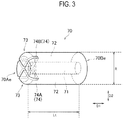
- the combustion type heat source 70 has a shape extending along a first direction D1 from an ignition end 70Ae toward a non-ignition end 70Be, as shown in Fig. 3 .
- the combustion type heat source 70 has a longitudinal hollow 71, a side wall 72, a chamfered portion 73 and grooves 74 (groove 74A and groove 74B).
- the longitudinal hollow 71 extends along the first direction D1 from the ignition end 70Ae toward the non-ignition end 70Be.
- the longitudinal hollow 71 is preferably provided at an approximately center of the combustion type heat source 70 in a perpendicular cross section perpendicular to the first direction D1. That is, the thickness of a wall body (side wall 72) configuring the longitudinal hollow 71 is preferably constant in the perpendicular cross section perpendicular to the first direction D1.
- the number of longitudinal hollows 71 formed in the combustion type heat source 70 is preferably singular.
- the longitudinal hollow 71 has a first cross section area in the perpendicular cross section perpendicular to the first direction D1.
- the first cross section area of the longitudinal hollow 71 is 1.77 mm 2 or more.
- the longitudinal hollow 71 is an example of a through hole extending along the predetermined direction.
- the air holes 52A provided to the bottom plate 52 of the cup 50 are preferably arranged at a position not overlapping with the longitudinal hollow 71.
- the combustion type heat source 70 is configured by a flammable substance.
- the flammable substance include a mixture including a carbonaceous material, a nonflammable additive, a binder (organic binder or inorganic binder), and water.
- a material which is obtained by removing a volatile impurity through a heat treatment, etc., is preferably used as the carbonaceous material.
- the combustion type heat source 70 preferably includes a carbonaceous material in a range of 30 wt% to 70 wt%, and more preferably includes a carbonaceous material in a range of 35 wt% to 45 wt%. In a case where the combustion type heat source 70 includes a carbonaceous material in the above-described preferable range, it is possible to achieve a more appropriate burning characteristic such as supply of a heat source, tightening of ashes, and the like.
- the organic binder it is possible to use a mixture including at least one of CMC-Na (carboxymethyl-cellulose sodium), CMC (carboxymethyl cellulose), alginate, EVA, PVA, PVAC, and saccharides.
- the inorganic binder it is possible to use a mineral-based binder such as purified bentonite or a silica-based binder such as colloidal silica, water glass, and calcium silicate.
- a mineral-based binder such as purified bentonite or a silica-based binder such as colloidal silica, water glass, and calcium silicate.
- the binder when the weight of the combustion type heat source 70 is 100 wt%, the binder preferably includes 1 wt% to 10 wt% of CMC-Na, and preferably includes 1 wt% to 8 wt% of CMC-Na.
- the nonflammable additive it is possible to use, for example, a carbonate or an oxide including sodium, potassium, calcium, magnesium and silicon.
- the combustion type heat source 70 may include 40 wt% to 89 wt% of the nonflammable additive.
- the combustion type heat source 70 preferably includes 45 wt% to 60 wt% of the nonflammable additive.
- the side wall 72 may include 1 wt% or less of alkali metal salts such as sodium chloride and potassium chloride when the weight of the combustion type heat source 70 is 100 wt%.
- the chamfered portion 73 is provided along an outer periphery of the ignition end 70Ae and has an inclination relative to the perpendicular cross section perpendicular to the first direction D1.
- the grooves 74 are formed at the ignition end 70Ae and communicates to the longitudinal hollow 71.
- the grooves 74 are configured by the groove 74A and the groove 74B, and the groove 74A and the groove 74B cross each other and have a straight-line shape.
- the size (Lt shown in Fig. 3 ) of the combustion type heat source 70 in the first direction D1 is preferably 5 mm or more and 30 mm or less, and more preferably 10 mm or more and 20 mm or less. Further, the size (R shown in Fig. 3 ) of the combustion type heat source 70 in a second direction D2 perpendicular to the first direction D1 is preferably 3 mm or more and 15 mm or less.
- the length (protruding length) of exposure of the combustion type heat source 70 from the holder 30 is preferably 5 mm or more and 15 mm or less, and more preferably 5 mm or more and 10 mm or less.
- the insertion length of the combustion type heat source 70 into the holder 30 is preferably 2 mm or more and 10 mm or less, and more preferably 2 mm or more and 5 mm or less.
- the size of the combustion type heat source 70 in the second direction D2 is an outer diameter of the combustion type heat source 70.
- the size of the combustion type heat source 70 in the second direction D2 is a maximum value of the combustion type heat source 70 in the second direction D2.
- the flavor source 90 is adjacent to the combustion type heat source 70 at the non-ignition end side in the predetermined direction.
- the flavor source 90 is configured by a plurality of flavor pieces.
- the plurality of flavor pieces may be general shredded tobacco used in a cigarette (paper-wrapped tobacco), or may be granular tobacco used in a snuff.
- the flavor source 90 may include, in addition to a tobacco raw material, an aerosol source such as glycerin and propylene glycol, and may include a desired flavoring agent.
- the cup 50 includes the claw portion 54 having at least the engagement portion 54A that engages the end surface of the combustion type heat source 70 at the non-ignition end side. Therefore, it is possible to appropriately control the insertion length of the combustion type heat source 70, and it is possible to appropriately control the filling density of the flavor pieces configuring the flavor source 90 and the length of the filled layer of the flavor pieces. As a result, it is possible to stably supply flavor to a user.
- the claw portion 54 has the holding portion 54B in addition to the engagement portion 54A. As a result, it is possible to control disengagement of the combustion type heat source 70. Further, the holding portion 54B has a tapered shape entering the inside of the cup 50 from the ignition end side toward the non-ignition end side. As a result, it is possible to control the disengagement of the combustion type heat source 70 even when there is a variation in an outer shape of the combustion type heat source 70.
- the cup 50 has the flange 53 that projects to the outside of the cup 50 from the outer periphery of the opening of the cup 50.
- the cup 50 is integrally formed by a heat conductive member.
- the heat of the combustion type heat source 70 is conveyed to the flavor source 90 via the side wall 51 of the cup 50, and thus, it is possible to effectively heat the flavor source 90.
- the cup 50 is integrally formed by stainless steel, and thus, it is possible to sufficiently maintain the strength of the cup 50 even when making the thickness of the side wall 51 of the cup 50 to be 0.1mm or less. It is noted that when the thickness of the side wall 51 of the cup 50 is 0.1mm or less, the heat of the combustion type heat source 70 is easily conveyed to the heat conductive member 33 via the side wall 51 of the cup 50.
- the cup 50 is configured of stainless steel, and thus, it is possible to obtain corrosion resistance of the cup 50 against the combustion type heat source 70 including a carbonaceous material.
- the air holes 52A formed in the bottom plate 52 of the cup 50 are arranged at a position not overlapping with the longitudinal hollow 71.
- the air inhaled from the longitudinal hollow 71 of the combustion type heat source 70 is diffused at the bottom plate 52 and a path through which the heat is conveyed from the combustion type heat source 70 is also diffused, and thus, it is possible to effectively heat the flavor source 90.
- the heat conductive member 33 covers at least a part of the side surface of the cup 50 and extends to the non-ignition end side relative to the end surface (bottom plate 52 described later) at the non-ignition end side of the cup 50.
- the heat of the combustion type heat source 70 is conveyed to the heat conductive member 33 via the side wall 51 of the cup 50, and thus, an excessive supply of heat to the body member 32 of the holder 30 is prevented and the burning or thermal decomposition of the body member 32 is possibly prevented.
- combustion type heat source 70 is held by the cup 50 and the combustion type heat source 70 does not directly contact with the heat conductive member 33, and thus, it is possible to suitably use, as the heat conductive member 33, a member such as aluminum having excellent heat conductivity but having corrosiveness against a carbonaceous material.
- the claw portion 54 has the engagement portion 54A and the holding portion 54B.
- the embodiment is not limited thereto.
- the claw portion 54 may not have the holding portion 54B and may be configured only by the engagement portion 54A.
- the combustion type heat source 70 has a shape shown in Fig. 3 .
- the combustion type heat source 70 may have a shape that is disclosed in Fig. 9 and Fig. 10 of International Publication WO 2013/146951 A1 .
- the combustion type heat source 70 has an ignition end portion having the ignition end 70Ae and a body integrally formed with an ignition end portion and having the non-ignition end 70Be.
- the above-described longitudinal hollow 71 is formed in the body.
- the ignition end portion has a gap connected to the longitudinal hollow 71 in an extended direction of the longitudinal hollow 71. The gap is formed separately from the above-described groove 74A and groove 74B.
- the cross sectional size of the gap is similar to the cross sectional size of the longitudinal hollow 71.
- the diameters ⁇ of the longitudinal hollow 71 and the gap are, for example, 1.0 mm or more and 2.5 mm or less.
- the groove widths of the groove 74A and the groove 74B are smaller than the diameters ⁇ of the longitudinal hollow 71 and the gap, and are, for example, 0.5 mm or more and 1.5 mm or less.
- the entire length (Lt shown in Fig. 3 ) of the combustion type heat source 70 in the predetermined direction is, for example, 10 mm or more and 20 mm or less.
- the length of the ignition end portion in the predetermined direction is, for example, 1 mm or more and 3 mm or less.
- the length of a region to which a chamfering process is performed is, for example, 0.5 mm. That is, in the predetermined direction, of the ignition end portion, the length of a region to which the chamfering process is not performed is, for example, 2.5 mm.
- a flavor inhaler and a cup that enable a stable supply of flavor to a user, by appropriately controlling the insertion length of a combustion type heat source as well as the filling density of flavor pieces configuring a flavor source and the length of a filled layer of the flavor pieces.
Description
- The present invention relates to a flavor inhaler extending along a direction from an ignition end toward a non-ignition end, and a cup used for the flavor inhaler.
- Conventionally, instead of cigarette, a flavor inhaler (smoking article) is proposed which allows for tasting flavor without burning a flavor source such as a tobacco. For example, there is known a flavor inhaler including: a combustion type heat source extending along a direction from an ignition end toward a non-ignition end (hereinafter, referred to as "longitudinal axis direction"); a flavor source configured by a tobacco material, etc.; and a holder configured to hold the combustion type heat source and the flavor source. There are various types of proposals for such a flavor inhaler.
- For example,
Patent Document 1 discloses a technology of holding the combustion type heat source and the flavor source by a container configured by a heat conductive member. The container has a cup shape having a bottom plate with a hole for introducing an aerosol generated from the flavor source to a non-ignition end side. - Patent Document 1:
US Patent No. 5105831 -
UA 5027837 A - A first feature is summarized as a flavor inhaler having the features of
claim 1. - According to a further embodiment, the cup has a flange that projects to an outside of the cup from an outer periphery of an opening of the cup.
- According to a further embodiment, an inner wall of the holder is provided with a heat conductive member that covers at least a part of a side surface of the cup and that extends to the non-ignition end side relative to the bottom plate of the cup.
- According to a further embodiment, the cup is integrally formed by a heat conductive member.
- According to a further embodiment, A seventh feature according to the sixth feature is summarized as that the heat conductie member is stainless steel.
- According to a further embodiment, a thickness of the cup is 0.1 mm or less.
- According to a further embodiment, the combustion type heat source has a through hole extending along the predetermined direction, an air hole is formed in the bottom plate of the cup, and the air hole is arranged at a position not overlapping with the through hole in a projection surface perpendicular to the predetermined direction.
- A tenth feature is summarized as a cup having the features of claim 8.
-
-
Fig. 1 is a diagram showing aflavor inhaler 100 according to a first embodiment. -
Fig. 2 is a diagram showing acup 50 according to the first embodiment. -
Fig. 3 is a diagram showing a combustiontype heat source 70 according to the first embodiment. - Hereinafter, the embodiments of the present invention will be described with reference to the drawings. In the following drawings, identical or similar components are denoted by identical or similar reference numerals. However, it should be noted that the drawings are schematic, and the ratio and the like of each of the dimensions is different from the reality.
- Therefore, specific dimensions should be determined with reference to the description below. It is needless to mention that different relationships and ratio of dimensions may be included in different drawings.
- For the flavor inhaler mentioned in background art, a length (insertion length) of a combustion type heat source to be inserted into a container (hereinafter, cup) having heat conductivity as well as filling density of a flavor source and a length of a filled layer of the flavor source have significant influence on a flavor supplied to a user. In particular, the insertion length of the combustion type heat source as well as the filling density of the flavor source and the length of the filled layer of the flavor source have significant influence on conductive heat transfer behavior from the combustion type heat source to the flavor source via the cup. Further, the filling density of the flavor source and the length of the filled layer of the flavor source also have significant influence on air-flow resistance of the flavor inhaler (that is, ease of inhaling when the user performs inhalation) and an amount of flavor component generated from the flavor source. Therefore, it is important to appropriately control these parameters.
- However, with the above-described container, it is difficult to appropriately control the insertion length of the combustion type heat source inserted into the container. Especially, when the flavor source is configured by a plurality of flavor pieces, the quantity (volume) of the flavor source is variable depending on the insertion length of the combustion type heat source, and thus, it is difficult to appropriately control the filling density of the flavor pieces configuring the flavor source and the length of the filled layer of the flavor pieces.
- The flavor inhaler according to the embodiment includes a tubular holder extending along a predetermined direction from an ignition end toward a non-ignition end. The flavor inhaler includes: a combustion type heat source provided at the ignition end; a flavor source that is adjacent to the combustion type heat source at the non-ignition end side in the predetermined direction and that is configured by a plurality of flavor pieces; and a cup configured to hold the combustion type heat source and to house the flavor source, the cup having cup shape. The cup is inserted into the holder in a direction in which an opening of the cup is directed toward the ignition end side and a bottom plate of the cup is arranged at the non-ignition end side. The cup has a claw portion that protrudes into the inside of the cup from an inner wall surface of a side wall of the cup. The claw portion has at least an engagement portion that engages an end surface of the combustion type heat source at a non-ignition end side.
- In the embodiment, the cup has a claw portion configured to have at least an engagement portion configured to engage an end surface of the combustion type heat source at the non-ignition end side. Therefore, it is possible to appropriately control the insertion length of the combustion type heat source, and it is possible to appropriately control the filling density and the length of the filled layer of flavor pieces configuring the flavor source. As a result, it is possible to stably supply flavor to a user.
- A flavor inhaler according to a first embodiment will be described, below.
Fig. 1 is a diagram showing aflavor inhaler 100 according to the first embodiment.Fig. 2 is a diagram showing acup 50 according to the first embodiment. - As shown in
Fig. 1 , theflavor inhaler 100 has aholder 30, acup 50, a combustiontype heat source 70, and aflavor source 90. In the first embodiment, it should be noted that theflavor inhaler 100 is a flavor inhaler without burning a flavor source. - The
holder 30 has a tubular shape extending along a predetermined direction from an ignition end toward a non-ignition end. For example, theholder 30 has a cylindrical shape or a rectangular tubular shape. In particular, theholder 30 has a hollow 31, abody member 32, and a heatconductive member 33. - The hollow 31 extends in the predetermined direction. The
body member 32 is, for example, a paper tube formed by bending a rectangular-shaped thick paper into a tubular shape after which the both edge portions of the thick paper are joined to each other. The heatconductive member 33 is arranged so as to cover at least a part of a side surface of thecup 50. Preferably, the heatconductive member 33 covers at least a part of the side surface of thecup 50 and extends to the non-ignition end side relative to the end surface (bottom plate 52 described later) at the non-ignition end side of thecup 50. That is, the heatconductive member 33 preferably covers at least a part of the side surface of thecup 50 and exposes to the hollow 31. The heatconductive member 33 is preferably formed of a metal material having an excellent heat conductivity, and is configured of aluminum, for example. - In the first embodiment, the
holder 30 is formed by laminating thebody member 32 and the heatconductive member 33. Specifically, theholder 30 includes: a thick paper that is thebody member 32; aluminum that is the heatconductive member 33, and is configured by an aluminum-clad paper formed by bending the thick paper and the aluminum into a cylindrical shape. In other words, both of thebody member 32 and the heatconductive member 33 have a tubular shape, and the heatconductive member 33 is provided over the entire inner wall of thebody member 32. It is noted that the embodiment is not limited thereto, and the heatconductive member 33 only needs to cover at least a part of the side surface of thecup 50. That is, the heatconductive member 33 may not necessarily have a tubular shape. - The
cup 50 has aside wall 51, abottom plate 52, aflange 53 and aclaw portion 54, as shown inFig. 2 . Thecup 50 has a cup shape configured by theside wall 51 and thebottom plate 52. Thecup 50 holds the combustiontype heat source 70, and houses theflavor source 90. Thecup 50 is inserted into theholder 30 in a direction in which an opening of the cup is directed toward the ignition end side and thebottom plate 52 of thecup 50 is arranged at the non-ignition end side. - The
side wall 51 has a tubular shape and thebottom plate 52 covers one of a pair of openings configured by theside wall 51. Anair hole 52A is formed in thebottom plate 52. For example, fourair holes 52A are formed in thebottom plate 52. The size of theair holes 52A is preferably smaller than the size of the flavor pieces configuring theflavor source 90. In a projection surface perpendicular to the predetermined direction, theair holes 52A are preferably arranged at a position not overlapping with a longitudinal hollow 71 provided in the combustiontype heat source 70 described later. - The
flange 53 has a shape projecting from an outer periphery of an opening of thecup 50 to the outside of thecup 50. Theflange 53 is engaged with an outer periphery of an opening of theholder 30 in a state where thecup 50 is inserted into theholder 30. - The
claw portion 54 has a shape protruding from an inner wall surface of theside wall 51 of thecup 50 to the inside of thecup 50. Theclaw portion 54 has anengagement portion 54A and a holdingportion 54B. - The
engagement portion 54A engages the end surface of the combustiontype heat source 70 at the non-ignition end side. Theengagement portion 54A is a plate-shaped portion having an inclination approximately parallel to thebottom plate 52, and is continued from the holdingportion 54B. - The holding
portion 54B holds a side surface of the combustiontype heat source 70. The holdingportion 54B is provided to the inner wall surface of theside wall 51 of thecup 50. The holdingportion 54B preferably has a tapered shape entering the inside of thecup 50 from the ignition end side toward the non-ignition end side. - The
claw portion 54 is not particularly limited, but is preferably configured by a pair of claw portions facing to each other. It is noted that, the embodiment is not limited thereto, and theclaw portion 54 may be configured by three or more claw portions. Alternatively, theclaw portion 54 may continue over the entire circumference of the inner wall surface of theside wall 51 of thecup 50. - In the first embodiment, the cup 50 (that is, the
side wall 51, thebottom plate 52, theflange 53 and the claw portion 54) is configured by a heat conductive member. Further, it is preferable that thecup 50 is integrally configured by the heat conductive member. For example, stainless steel is preferably used as the heat conductive member. For example, it is possible to use SUS430 as the stainless steel. In a case where thecup 50 is configured of stainless steel, the thickness of theside wall 51 of thecup 50 is preferably 0.1mm or less. - The combustion
type heat source 70 has a shape extending along a first direction D1 from an ignition end 70Ae toward a non-ignition end 70Be, as shown inFig. 3 . The combustiontype heat source 70 has a longitudinal hollow 71, aside wall 72, a chamferedportion 73 and grooves 74 (groove 74A and groove 74B). - The longitudinal hollow 71 extends along the first direction D1 from the ignition end 70Ae toward the non-ignition end 70Be. The longitudinal hollow 71 is preferably provided at an approximately center of the combustion
type heat source 70 in a perpendicular cross section perpendicular to the first direction D1. That is, the thickness of a wall body (side wall 72) configuring the longitudinal hollow 71 is preferably constant in the perpendicular cross section perpendicular to the first direction D1. - In the first embodiment, the number of
longitudinal hollows 71 formed in the combustiontype heat source 70 is preferably singular. The longitudinal hollow 71 has a first cross section area in the perpendicular cross section perpendicular to the first direction D1. The first cross section area of the longitudinal hollow 71 is 1.77 mm2 or more. - In the first embodiment, the longitudinal hollow 71 is an example of a through hole extending along the predetermined direction. In the projection surface perpendicular to the predetermined direction, the
air holes 52A provided to thebottom plate 52 of thecup 50 are preferably arranged at a position not overlapping with the longitudinal hollow 71. - The combustion
type heat source 70 is configured by a flammable substance. For example, examples of the flammable substance include a mixture including a carbonaceous material, a nonflammable additive, a binder (organic binder or inorganic binder), and water. A material which is obtained by removing a volatile impurity through a heat treatment, etc., is preferably used as the carbonaceous material. - When the weight of the combustion
type heat source 70 is 100 wt%, the combustiontype heat source 70 preferably includes a carbonaceous material in a range of 30 wt% to 70 wt%, and more preferably includes a carbonaceous material in a range of 35 wt% to 45 wt%. In a case where the combustiontype heat source 70 includes a carbonaceous material in the above-described preferable range, it is possible to achieve a more appropriate burning characteristic such as supply of a heat source, tightening of ashes, and the like. - For example, as the organic binder, it is possible to use a mixture including at least one of CMC-Na (carboxymethyl-cellulose sodium), CMC (carboxymethyl cellulose), alginate, EVA, PVA, PVAC, and saccharides.
- For example, as the inorganic binder, it is possible to use a mineral-based binder such as purified bentonite or a silica-based binder such as colloidal silica, water glass, and calcium silicate.
- For example, in view of a flavor, when the weight of the combustion
type heat source 70 is 100 wt%, the binder preferably includes 1 wt% to 10 wt% of CMC-Na, and preferably includes 1 wt% to 8 wt% of CMC-Na. - As the nonflammable additive, it is possible to use, for example, a carbonate or an oxide including sodium, potassium, calcium, magnesium and silicon. When the weight of the combustion
type heat source 70 is 100 wt%., the combustiontype heat source 70 may include 40 wt% to 89 wt% of the nonflammable additive. Further, in a case where calcium carbonate is used as the nonflammable additive, the combustiontype heat source 70 preferably includes 45 wt% to 60 wt% of the nonflammable additive. - In order to improve a burning characteristic, the
side wall 72 may include 1 wt% or less of alkali metal salts such as sodium chloride and potassium chloride when the weight of the combustiontype heat source 70 is 100 wt%. - The chamfered
portion 73 is provided along an outer periphery of the ignition end 70Ae and has an inclination relative to the perpendicular cross section perpendicular to the first direction D1. - The
grooves 74 are formed at the ignition end 70Ae and communicates to the longitudinal hollow 71. Thegrooves 74 are configured by thegroove 74A and thegroove 74B, and thegroove 74A and thegroove 74B cross each other and have a straight-line shape. - In the first embodiment, the size (Lt shown in
Fig. 3 ) of the combustiontype heat source 70 in the first direction D1 is preferably 5 mm or more and 30 mm or less, and more preferably 10 mm or more and 20 mm or less. Further, the size (R shown inFig. 3 ) of the combustiontype heat source 70 in a second direction D2 perpendicular to the first direction D1 is preferably 3 mm or more and 15 mm or less. - In the first embodiment, the length (protruding length) of exposure of the combustion
type heat source 70 from theholder 30 is preferably 5 mm or more and 15 mm or less, and more preferably 5 mm or more and 10 mm or less. On the other hand, the insertion length of the combustiontype heat source 70 into theholder 30 is preferably 2 mm or more and 10 mm or less, and more preferably 2 mm or more and 5 mm or less. - Here, in a case where the combustion
type heat source 70 has a cylindrical shape, the size of the combustiontype heat source 70 in the second direction D2 is an outer diameter of the combustiontype heat source 70. In a case where the combustiontype heat source 70 does not have a cylindrical shape, the size of the combustiontype heat source 70 in the second direction D2 is a maximum value of the combustiontype heat source 70 in the second direction D2. - The
flavor source 90 is adjacent to the combustiontype heat source 70 at the non-ignition end side in the predetermined direction. Theflavor source 90 is configured by a plurality of flavor pieces. For example, it is possible to use a tobacco raw material as theflavor source 90. In such a case, the plurality of flavor pieces may be general shredded tobacco used in a cigarette (paper-wrapped tobacco), or may be granular tobacco used in a snuff. Further, theflavor source 90 may include, in addition to a tobacco raw material, an aerosol source such as glycerin and propylene glycol, and may include a desired flavoring agent. - In the first embodiment, the
cup 50 includes theclaw portion 54 having at least theengagement portion 54A that engages the end surface of the combustiontype heat source 70 at the non-ignition end side. Therefore, it is possible to appropriately control the insertion length of the combustiontype heat source 70, and it is possible to appropriately control the filling density of the flavor pieces configuring theflavor source 90 and the length of the filled layer of the flavor pieces. As a result, it is possible to stably supply flavor to a user. - In the first embodiment, the
claw portion 54 has the holdingportion 54B in addition to theengagement portion 54A. As a result, it is possible to control disengagement of the combustiontype heat source 70. Further, the holdingportion 54B has a tapered shape entering the inside of thecup 50 from the ignition end side toward the non-ignition end side. As a result, it is possible to control the disengagement of the combustiontype heat source 70 even when there is a variation in an outer shape of the combustiontype heat source 70. - In the first embodiment, the
cup 50 has theflange 53 that projects to the outside of thecup 50 from the outer periphery of the opening of thecup 50. As a result, it is possible to constantly maintain the insertion length of thecup 50 relative to theholder 30 even when a mechanism configured to control the insertion length of thecup 50 relative to theholder 30 is not provided in theholder 30. Further, it is possible to constantly maintain the insertion length of the combustiontype heat source 70 relative to theholder 30, and it is also possible to constantly maintain the length (protruding length) of exposure of the combustiontype heat source 70 from theholder 30. The protruding length of the combustiontype heat source 70 is constant, and thus, it is possible to secure a burning period during which a predetermined times of puffing is performed, and then it is possible to stabilize the burning characteristic of the combustiontype heat source 70. - In the first embodiment, the
cup 50 is integrally formed by a heat conductive member. As a result, the heat of the combustiontype heat source 70 is conveyed to theflavor source 90 via theside wall 51 of thecup 50, and thus, it is possible to effectively heat theflavor source 90. Further, thecup 50 is integrally formed by stainless steel, and thus, it is possible to sufficiently maintain the strength of thecup 50 even when making the thickness of theside wall 51 of thecup 50 to be 0.1mm or less. It is noted that when the thickness of theside wall 51 of thecup 50 is 0.1mm or less, the heat of the combustiontype heat source 70 is easily conveyed to the heatconductive member 33 via theside wall 51 of thecup 50. Further, thecup 50 is configured of stainless steel, and thus, it is possible to obtain corrosion resistance of thecup 50 against the combustiontype heat source 70 including a carbonaceous material. - In the first embodiment, in the projection surface perpendicular to the predetermined direction, the
air holes 52A formed in thebottom plate 52 of thecup 50 are arranged at a position not overlapping with the longitudinal hollow 71. As a result, the air inhaled from the longitudinal hollow 71 of the combustiontype heat source 70 is diffused at thebottom plate 52 and a path through which the heat is conveyed from the combustiontype heat source 70 is also diffused, and thus, it is possible to effectively heat theflavor source 90. - In the first embodiment, the heat
conductive member 33 covers at least a part of the side surface of thecup 50 and extends to the non-ignition end side relative to the end surface (bottom plate 52 described later) at the non-ignition end side of thecup 50. As a result, the heat of the combustiontype heat source 70 is conveyed to the heatconductive member 33 via theside wall 51 of thecup 50, and thus, an excessive supply of heat to thebody member 32 of theholder 30 is prevented and the burning or thermal decomposition of thebody member 32 is possibly prevented. Further, the combustiontype heat source 70 is held by thecup 50 and the combustiontype heat source 70 does not directly contact with the heatconductive member 33, and thus, it is possible to suitably use, as the heatconductive member 33, a member such as aluminum having excellent heat conductivity but having corrosiveness against a carbonaceous material. - The present invention is described through the above-described embodiments, but it should not be understood that this invention is limited by the statements and the drawings constituting a part of this disclosure. From this disclosure, various alternative embodiments, examples, and operational technologies will become apparent to those skilled in the art.
- In the embodiment, a case is illustrated in which the
claw portion 54 has theengagement portion 54A and the holdingportion 54B. However, the embodiment is not limited thereto. For example, theclaw portion 54 may not have the holdingportion 54B and may be configured only by theengagement portion 54A. - In the embodiment, a case is illustrated in which the combustion
type heat source 70 has a shape shown inFig. 3 . However, the embodiment is not limited thereto. The combustiontype heat source 70 may have a shape that is disclosed in Fig. 9 and Fig. 10 of International PublicationWO 2013/146951 A1 . Specifically, the combustiontype heat source 70 has an ignition end portion having the ignition end 70Ae and a body integrally formed with an ignition end portion and having the non-ignition end 70Be. The above-described longitudinal hollow 71 is formed in the body. The ignition end portion has a gap connected to the longitudinal hollow 71 in an extended direction of the longitudinal hollow 71. The gap is formed separately from the above-describedgroove 74A and groove 74B. The cross sectional size of the gap is similar to the cross sectional size of the longitudinal hollow 71.
In such a case, when the cross sections of the longitudinal hollow 71 and the gap are circular-shaped, the diameters φ of the longitudinal hollow 71 and the gap are, for example, 1.0 mm or more and 2.5 mm or less. The groove widths of thegroove 74A and thegroove 74B are smaller than the diameters φ of the longitudinal hollow 71 and the gap, and are, for example, 0.5 mm or more and 1.5 mm or less. The entire length (Lt shown inFig. 3 ) of the combustiontype heat source 70 in the predetermined direction is, for example, 10 mm or more and 20 mm or less. The length of the ignition end portion in the predetermined direction is, for example, 1 mm or more and 3 mm or less. In the predetermined direction, of the ignition end portion, the length of a region to which a chamfering process is performed is, for example, 0.5 mm. That is, in the predetermined direction, of the ignition end portion, the length of a region to which the chamfering process is not performed is, for example, 2.5 mm. - According to the embodiment, it is possible to provide a flavor inhaler and a cup that enable a stable supply of flavor to a user, by appropriately controlling the insertion length of a combustion type heat source as well as the filling density of flavor pieces configuring a flavor source and the length of a filled layer of the flavor pieces.
Claims (8)
- A flavor inhaler (100) comprising:a tubular holder (30) extending along a predetermined direction from an ignition end toward a non-ignition end;a combustion type heat source (70) provided at the ignition end;a flavor source (90) adjacent to the combustion type heat source (70) at the non-ignition end side in the predetermined direction, the flavor source (90) configured by a plurality of flavor pieces; anda cup (50) configured to hold the combustion type heat source (70) and to house the flavor source (90), the cup (50) having a cup shape, whereinthe cup (50) is inserted into the holder (30) in a direction in which an opening of the cup (50) is directed toward the ignition end side and a bottom plate (52) of the cup (50) is arranged at the non-ignition end side,the cup (50) has a claw portion (54) that protrudes into an inside of the cup (50) from an inner wall surface of a side wall (51) of the cup (50),the claw portion (54) has at least an engagement portion (54A) that engages an end surface of the combustion type heat source (70) in a non-ignition end side,the claw portion (54) has, in addition to the engagement portion (54A), a holding portion (54B) configured to hold a side surface of the combustion type heat source (70),the engagement portion (54A) is continued from the holding portion (54B), characterized in thatthe holding portion (54B) has a tapered shape entering an inside of the cup (50) from the ignition end side toward the non-ignition end side.
- The flavor inhaler according to claim 1, wherein
the cup (50) has a flange (53) that projects to an outside of the cup (50) from an outer periphery of an opening of the cup (50). - The flavor inhaler according to claim 1, wherein
an inner wall of the holder (30) is provided with a heat conductive member (33) that covers at least a part of a side surface of the cup (50) and that extends to the non-ignition end side relative to the bottom plate (52) of the cup (50). - The flavor inhaler according to claim 1, wherein
the cup (50) is integrally formed by a heat conductive member (33). - The flavor inhaler according to claim 4, wherein
the heat conductive member (33) is stainless steel. - The flavor inhaler according to claim 4, wherein
a thickness of the cup (50) is 0.1 mm or less. - The flavor inhaler according to claim 1, wherein
the combustion type heat source (70) has a through hole extending along the predetermined direction,
an air hole (52A) is formed in the bottom plate (52) of the cup (50), and
the air hole (52A) is arranged at a position not overlapping with the through hole in a projection surface perpendicular to the predetermined direction. - A cup (50) configured to hold a combustion type heat source (70) and to house a flavor source (90) configured by a plurality of flavor pieces, the cup (50) being applied to a flavor inhaler (100) including the combustion type heat source (70) and the flavor source (90), comprising:a body (32) having a cup shape; anda claw portion (54) that protrudes into an inside of the body (32) from an inner wall surface of a side wall (51) of the body (32), whereinthe claw portion (54) has at least an engagement portion (54A) configured to engage an end surface of the combustion type heat source (70) at a non-ignition end side,the claw portion (54) has, in addition to the engagement portion (54A), a holding portion (54B) configured to hold a side surface of the combustion type heat source (70),the engagement portion (54A) is continued from the holding portion (54B), characterized in thatthe holding portion (54B) has a tapered shape entering an inside of the cup (50) toward the engagement portion (54A).
Applications Claiming Priority (2)
| Application Number | Priority Date | Filing Date | Title |
|---|---|---|---|
| JP2014101658 | 2014-05-15 | ||
| PCT/JP2015/063727 WO2015174442A1 (en) | 2014-05-15 | 2015-05-13 | Flavor inhaler and cup member |
Publications (3)
| Publication Number | Publication Date |
|---|---|
| EP3146854A1 EP3146854A1 (en) | 2017-03-29 |
| EP3146854A4 EP3146854A4 (en) | 2018-04-18 |
| EP3146854B1 true EP3146854B1 (en) | 2019-07-10 |
Family
ID=54479979
Family Applications (1)
| Application Number | Title | Priority Date | Filing Date |
|---|---|---|---|
| EP15792132.1A Active EP3146854B1 (en) | 2014-05-15 | 2015-05-13 | Flavor inhaler and cup member |
Country Status (6)
| Country | Link |
|---|---|
| US (1) | US11160302B2 (en) |
| EP (1) | EP3146854B1 (en) |
| JP (1) | JP6255489B2 (en) |
| ES (1) | ES2747626T3 (en) |
| TW (1) | TW201545673A (en) |
| WO (1) | WO2015174442A1 (en) |
Families Citing this family (18)
| Publication number | Priority date | Publication date | Assignee | Title |
|---|---|---|---|---|
| TR201908063T4 (en) * | 2015-03-31 | 2019-06-21 | Philip Morris Products Sa | Smoking product having an ignitable heat source gripping means. |
| KR101930194B1 (en) * | 2015-04-06 | 2018-12-17 | 니뽄 다바코 산교 가부시키가이샤 | Flavor inhaler and inside holding member |
| US11744296B2 (en) | 2015-12-10 | 2023-09-05 | R. J. Reynolds Tobacco Company | Smoking article |
| US10314334B2 (en) | 2015-12-10 | 2019-06-11 | R.J. Reynolds Tobacco Company | Smoking article |
| WO2017187556A1 (en) * | 2016-04-27 | 2017-11-02 | 日本たばこ産業株式会社 | Flavor inhaler |
| WO2017187555A1 (en) * | 2016-04-27 | 2017-11-02 | 日本たばこ産業株式会社 | Flavor inhaler |
| KR102290700B1 (en) * | 2016-07-01 | 2021-08-17 | 니뽄 다바코 산교 가부시키가이샤 | Method for manufacturing flavor aspirator and combustion heat source |
| EA038812B1 (en) * | 2016-07-01 | 2021-10-22 | Джапан Тобакко Инк. | Flavor inhaler |
| TWI682728B (en) * | 2016-07-01 | 2020-01-21 | 日商日本煙草產業股份有限公司 | Flavor aspirator and method for manufacturing combustion type heat source |
| US11723399B2 (en) | 2018-07-13 | 2023-08-15 | R.J. Reynolds Tobacco Company | Smoking article with detachable cartridge |
| US11395510B2 (en) | 2019-07-19 | 2022-07-26 | R.J. Reynolds Tobacco Company | Aerosol delivery device with rotatable enclosure for cartridge |
| US11330838B2 (en) | 2019-07-19 | 2022-05-17 | R. J. Reynolds Tobacco Company | Holder for aerosol delivery device with detachable cartridge |
| KR102535306B1 (en) | 2020-02-07 | 2023-05-22 | 주식회사 케이티앤지 | Aerosol generating device and aerosol generating system comprising thereof |
| US11589616B2 (en) | 2020-04-29 | 2023-02-28 | R.J. Reynolds Tobacco Company | Aerosol delivery device with sliding and axially rotating locking mechanism |
| US11439185B2 (en) | 2020-04-29 | 2022-09-13 | R. J. Reynolds Tobacco Company | Aerosol delivery device with sliding and transversely rotating locking mechanism |
| WO2022187934A1 (en) * | 2021-03-12 | 2022-09-15 | Hexo Operations Inc. | Apparatus and methods for consumption of single-use load of smokable material |
| US11825872B2 (en) | 2021-04-02 | 2023-11-28 | R.J. Reynolds Tobacco Company | Aerosol delivery device with protective sleeve |
| US11953362B2 (en) | 2021-05-12 | 2024-04-09 | Conrad Franklin Montville | Dispensing device |
Family Cites Families (19)
| Publication number | Priority date | Publication date | Assignee | Title |
|---|---|---|---|---|
| US3964339A (en) * | 1975-05-19 | 1976-06-22 | Air Products And Chemicals, Inc. | End holders for handle bars |
| JPS5338477A (en) * | 1976-09-16 | 1978-04-08 | Setsuo Kuroki | Cigarette pipe |
| US4219032A (en) * | 1977-11-30 | 1980-08-26 | Reiner Steven H | Smoking device |
| US4585014A (en) * | 1983-08-01 | 1986-04-29 | Fry Arnold H | Fire inhibiting tubular safety shield for a cigarette type smoking device and combination thereof |
| US4793365A (en) | 1984-09-14 | 1988-12-27 | R. J. Reynolds Tobacco Company | Smoking article |
| US5105831A (en) * | 1985-10-23 | 1992-04-21 | R. J. Reynolds Tobacco Company | Smoking article with conductive aerosol chamber |
| US4756318A (en) * | 1985-10-28 | 1988-07-12 | R. J. Reynolds Tobacco Company | Smoking article with tobacco jacket |
| US4713020A (en) * | 1987-01-29 | 1987-12-15 | E. I. Du Pont De Nemours And Company | Connector unit |
| IN172374B (en) * | 1988-05-16 | 1993-07-10 | Reynolds Tobacco Co R | |
| US5345951A (en) * | 1988-07-22 | 1994-09-13 | Philip Morris Incorporated | Smoking article |
| US4966171A (en) * | 1988-07-22 | 1990-10-30 | Philip Morris Incorporated | Smoking article |
| KR910021225A (en) * | 1990-02-27 | 1991-12-20 | 지.로보트 디 마르코 | cigarette |
| US5027837A (en) * | 1990-02-27 | 1991-07-02 | R. J. Reynolds Tobacco Company | Cigarette |
| GB2322483B (en) * | 1997-02-24 | 1999-01-06 | Itt Mfg Enterprises Inc | Electrical connector |
| ATE400192T1 (en) * | 2001-12-28 | 2008-07-15 | Japan Tobacco Inc | SMOKING DEVICE |
| WO2009027959A1 (en) * | 2007-08-28 | 2009-03-05 | Oglesby & Butler Research & Development Limited | A gas powered heating unit and a heat not burn vaporising device |
| EP2893822B2 (en) | 2010-03-26 | 2022-08-03 | Japan Tobacco Inc. | Smoking article |
| TW201410163A (en) * | 2012-07-19 | 2014-03-16 | Philip Morris Prod | Smoking article having reduced sidestream smoke |
| JP5960342B2 (en) * | 2013-03-05 | 2016-08-02 | 日本たばこ産業株式会社 | Combustion type heat source, flavor inhaler, and method of manufacturing combustion type heat source |
-
2015
- 2015-05-13 EP EP15792132.1A patent/EP3146854B1/en active Active
- 2015-05-13 WO PCT/JP2015/063727 patent/WO2015174442A1/en active Application Filing
- 2015-05-13 JP JP2016519283A patent/JP6255489B2/en active Active
- 2015-05-13 ES ES15792132T patent/ES2747626T3/en active Active
- 2015-05-15 TW TW104115519A patent/TW201545673A/en unknown
-
2016
- 2016-11-14 US US15/351,073 patent/US11160302B2/en active Active
Non-Patent Citations (1)
| Title |
|---|
| None * |
Also Published As
| Publication number | Publication date |
|---|---|
| US20170055578A1 (en) | 2017-03-02 |
| EP3146854A1 (en) | 2017-03-29 |
| WO2015174442A1 (en) | 2015-11-19 |
| JPWO2015174442A1 (en) | 2017-04-20 |
| ES2747626T3 (en) | 2020-03-11 |
| US11160302B2 (en) | 2021-11-02 |
| JP6255489B2 (en) | 2017-12-27 |
| TW201545673A (en) | 2015-12-16 |
| EP3146854A4 (en) | 2018-04-18 |
Similar Documents
| Publication | Publication Date | Title |
|---|---|---|
| EP3146854B1 (en) | Flavor inhaler and cup member | |
| JP7383077B2 (en) | smoking articles | |
| EP3284354B1 (en) | Flavor inhaler | |
| JP2020022498A (en) | Heat generator for aerosol generation for smoking article, related smoking article | |
| JP6227555B2 (en) | Smoking article with front plug and method thereof | |
| EP3199044B1 (en) | Burning type heat source, flavor inhaler, and manufacturing method of burning type heat source | |
| JP6966995B2 (en) | Multi-segment components for aerosol-generating articles | |
| US10524506B2 (en) | Burning type heat source and flavor inhaler | |
| KR20180097533A (en) | Aerosol generating component for use in an aerosol generating article | |
| EP3260001B1 (en) | Flavor inhaler and inside holding member | |
| WO2013146951A2 (en) | Carbon heat source and flavour inhalation tool | |
| WO2018060805A1 (en) | Extinguisher for aerosol generating article | |
| TWI615100B (en) | Smoking article with dual function cap , use of a removable cap , a method of using a smoking article , and a method of facilitating disposal of a smoking article | |
| KR101888282B1 (en) | Flavor inhalator |
Legal Events
| Date | Code | Title | Description |
|---|---|---|---|
| STAA | Information on the status of an ep patent application or granted ep patent |
Free format text: STATUS: THE INTERNATIONAL PUBLICATION HAS BEEN MADE |
|
| PUAI | Public reference made under article 153(3) epc to a published international application that has entered the european phase |
Free format text: ORIGINAL CODE: 0009012 |
|
| STAA | Information on the status of an ep patent application or granted ep patent |
Free format text: STATUS: REQUEST FOR EXAMINATION WAS MADE |
|
| 17P | Request for examination filed |
Effective date: 20161215 |
|
| AK | Designated contracting states |
Kind code of ref document: A1 Designated state(s): AL AT BE BG CH CY CZ DE DK EE ES FI FR GB GR HR HU IE IS IT LI LT LU LV MC MK MT NL NO PL PT RO RS SE SI SK SM TR |
|
| AX | Request for extension of the european patent |
Extension state: BA ME |
|
| DAV | Request for validation of the european patent (deleted) | ||
| DAX | Request for extension of the european patent (deleted) | ||
| A4 | Supplementary search report drawn up and despatched |
Effective date: 20180319 |
|
| RIC1 | Information provided on ipc code assigned before grant |
Ipc: A24F 47/00 20060101AFI20180313BHEP Ipc: A24B 15/16 20060101ALI20180313BHEP |
|
| GRAP | Despatch of communication of intention to grant a patent |
Free format text: ORIGINAL CODE: EPIDOSNIGR1 |
|
| STAA | Information on the status of an ep patent application or granted ep patent |
Free format text: STATUS: GRANT OF PATENT IS INTENDED |
|
| INTG | Intention to grant announced |
Effective date: 20190118 |
|
| GRAS | Grant fee paid |
Free format text: ORIGINAL CODE: EPIDOSNIGR3 |
|
| GRAA | (expected) grant |
Free format text: ORIGINAL CODE: 0009210 |
|
| STAA | Information on the status of an ep patent application or granted ep patent |
Free format text: STATUS: THE PATENT HAS BEEN GRANTED |
|
| RAP1 | Party data changed (applicant data changed or rights of an application transferred) |
Owner name: JAPAN TOBACCO INC. |
|
| AK | Designated contracting states |
Kind code of ref document: B1 Designated state(s): AL AT BE BG CH CY CZ DE DK EE ES FI FR GB GR HR HU IE IS IT LI LT LU LV MC MK MT NL NO PL PT RO RS SE SI SK SM TR |
|
| REG | Reference to a national code |
Ref country code: GB Ref legal event code: FG4D |
|
| REG | Reference to a national code |
Ref country code: CH Ref legal event code: EP Ref country code: AT Ref legal event code: REF Ref document number: 1152617 Country of ref document: AT Kind code of ref document: T Effective date: 20190715 |
|
| REG | Reference to a national code |
Ref country code: DE Ref legal event code: R096 Ref document number: 602015033611 Country of ref document: DE |
|
| REG | Reference to a national code |
Ref country code: IE Ref legal event code: FG4D |
|
| REG | Reference to a national code |
Ref country code: CH Ref legal event code: NV Representative=s name: NOVAGRAAF INTERNATIONAL SA, CH |
|
| REG | Reference to a national code |
Ref country code: NL Ref legal event code: MP Effective date: 20190710 |
|
| REG | Reference to a national code |
Ref country code: LT Ref legal event code: MG4D |
|
| REG | Reference to a national code |
Ref country code: AT Ref legal event code: MK05 Ref document number: 1152617 Country of ref document: AT Kind code of ref document: T Effective date: 20190710 |
|
| PG25 | Lapsed in a contracting state [announced via postgrant information from national office to epo] |
Ref country code: FI Free format text: LAPSE BECAUSE OF FAILURE TO SUBMIT A TRANSLATION OF THE DESCRIPTION OR TO PAY THE FEE WITHIN THE PRESCRIBED TIME-LIMIT Effective date: 20190710 Ref country code: LT Free format text: LAPSE BECAUSE OF FAILURE TO SUBMIT A TRANSLATION OF THE DESCRIPTION OR TO PAY THE FEE WITHIN THE PRESCRIBED TIME-LIMIT Effective date: 20190710 Ref country code: AT Free format text: LAPSE BECAUSE OF FAILURE TO SUBMIT A TRANSLATION OF THE DESCRIPTION OR TO PAY THE FEE WITHIN THE PRESCRIBED TIME-LIMIT Effective date: 20190710 Ref country code: PT Free format text: LAPSE BECAUSE OF FAILURE TO SUBMIT A TRANSLATION OF THE DESCRIPTION OR TO PAY THE FEE WITHIN THE PRESCRIBED TIME-LIMIT Effective date: 20191111 Ref country code: NL Free format text: LAPSE BECAUSE OF FAILURE TO SUBMIT A TRANSLATION OF THE DESCRIPTION OR TO PAY THE FEE WITHIN THE PRESCRIBED TIME-LIMIT Effective date: 20190710 Ref country code: BG Free format text: LAPSE BECAUSE OF FAILURE TO SUBMIT A TRANSLATION OF THE DESCRIPTION OR TO PAY THE FEE WITHIN THE PRESCRIBED TIME-LIMIT Effective date: 20191010 Ref country code: NO Free format text: LAPSE BECAUSE OF FAILURE TO SUBMIT A TRANSLATION OF THE DESCRIPTION OR TO PAY THE FEE WITHIN THE PRESCRIBED TIME-LIMIT Effective date: 20191010 Ref country code: HR Free format text: LAPSE BECAUSE OF FAILURE TO SUBMIT A TRANSLATION OF THE DESCRIPTION OR TO PAY THE FEE WITHIN THE PRESCRIBED TIME-LIMIT Effective date: 20190710 Ref country code: SE Free format text: LAPSE BECAUSE OF FAILURE TO SUBMIT A TRANSLATION OF THE DESCRIPTION OR TO PAY THE FEE WITHIN THE PRESCRIBED TIME-LIMIT Effective date: 20190710 |
|
| PG25 | Lapsed in a contracting state [announced via postgrant information from national office to epo] |
Ref country code: RS Free format text: LAPSE BECAUSE OF FAILURE TO SUBMIT A TRANSLATION OF THE DESCRIPTION OR TO PAY THE FEE WITHIN THE PRESCRIBED TIME-LIMIT Effective date: 20190710 Ref country code: GR Free format text: LAPSE BECAUSE OF FAILURE TO SUBMIT A TRANSLATION OF THE DESCRIPTION OR TO PAY THE FEE WITHIN THE PRESCRIBED TIME-LIMIT Effective date: 20191011 Ref country code: IS Free format text: LAPSE BECAUSE OF FAILURE TO SUBMIT A TRANSLATION OF THE DESCRIPTION OR TO PAY THE FEE WITHIN THE PRESCRIBED TIME-LIMIT Effective date: 20191110 Ref country code: AL Free format text: LAPSE BECAUSE OF FAILURE TO SUBMIT A TRANSLATION OF THE DESCRIPTION OR TO PAY THE FEE WITHIN THE PRESCRIBED TIME-LIMIT Effective date: 20190710 Ref country code: LV Free format text: LAPSE BECAUSE OF FAILURE TO SUBMIT A TRANSLATION OF THE DESCRIPTION OR TO PAY THE FEE WITHIN THE PRESCRIBED TIME-LIMIT Effective date: 20190710 |
|
| REG | Reference to a national code |
Ref country code: ES Ref legal event code: FG2A Ref document number: 2747626 Country of ref document: ES Kind code of ref document: T3 Effective date: 20200311 |
|
| PG25 | Lapsed in a contracting state [announced via postgrant information from national office to epo] |
Ref country code: TR Free format text: LAPSE BECAUSE OF FAILURE TO SUBMIT A TRANSLATION OF THE DESCRIPTION OR TO PAY THE FEE WITHIN THE PRESCRIBED TIME-LIMIT Effective date: 20190710 |
|
| PG25 | Lapsed in a contracting state [announced via postgrant information from national office to epo] |
Ref country code: RO Free format text: LAPSE BECAUSE OF FAILURE TO SUBMIT A TRANSLATION OF THE DESCRIPTION OR TO PAY THE FEE WITHIN THE PRESCRIBED TIME-LIMIT Effective date: 20190710 Ref country code: EE Free format text: LAPSE BECAUSE OF FAILURE TO SUBMIT A TRANSLATION OF THE DESCRIPTION OR TO PAY THE FEE WITHIN THE PRESCRIBED TIME-LIMIT Effective date: 20190710 Ref country code: PL Free format text: LAPSE BECAUSE OF FAILURE TO SUBMIT A TRANSLATION OF THE DESCRIPTION OR TO PAY THE FEE WITHIN THE PRESCRIBED TIME-LIMIT Effective date: 20190710 Ref country code: DK Free format text: LAPSE BECAUSE OF FAILURE TO SUBMIT A TRANSLATION OF THE DESCRIPTION OR TO PAY THE FEE WITHIN THE PRESCRIBED TIME-LIMIT Effective date: 20190710 |
|
| PG25 | Lapsed in a contracting state [announced via postgrant information from national office to epo] |
Ref country code: SK Free format text: LAPSE BECAUSE OF FAILURE TO SUBMIT A TRANSLATION OF THE DESCRIPTION OR TO PAY THE FEE WITHIN THE PRESCRIBED TIME-LIMIT Effective date: 20190710 Ref country code: CZ Free format text: LAPSE BECAUSE OF FAILURE TO SUBMIT A TRANSLATION OF THE DESCRIPTION OR TO PAY THE FEE WITHIN THE PRESCRIBED TIME-LIMIT Effective date: 20190710 Ref country code: IS Free format text: LAPSE BECAUSE OF FAILURE TO SUBMIT A TRANSLATION OF THE DESCRIPTION OR TO PAY THE FEE WITHIN THE PRESCRIBED TIME-LIMIT Effective date: 20200224 Ref country code: SM Free format text: LAPSE BECAUSE OF FAILURE TO SUBMIT A TRANSLATION OF THE DESCRIPTION OR TO PAY THE FEE WITHIN THE PRESCRIBED TIME-LIMIT Effective date: 20190710 |
|
| REG | Reference to a national code |
Ref country code: DE Ref legal event code: R097 Ref document number: 602015033611 Country of ref document: DE |
|
| PLBE | No opposition filed within time limit |
Free format text: ORIGINAL CODE: 0009261 |
|
| STAA | Information on the status of an ep patent application or granted ep patent |
Free format text: STATUS: NO OPPOSITION FILED WITHIN TIME LIMIT |
|
| PG2D | Information on lapse in contracting state deleted |
Ref country code: IS |
|
| 26N | No opposition filed |
Effective date: 20200603 |
|
| PG25 | Lapsed in a contracting state [announced via postgrant information from national office to epo] |
Ref country code: SI Free format text: LAPSE BECAUSE OF FAILURE TO SUBMIT A TRANSLATION OF THE DESCRIPTION OR TO PAY THE FEE WITHIN THE PRESCRIBED TIME-LIMIT Effective date: 20190710 |
|
| PG25 | Lapsed in a contracting state [announced via postgrant information from national office to epo] |
Ref country code: MC Free format text: LAPSE BECAUSE OF FAILURE TO SUBMIT A TRANSLATION OF THE DESCRIPTION OR TO PAY THE FEE WITHIN THE PRESCRIBED TIME-LIMIT Effective date: 20190710 |
|
| REG | Reference to a national code |
Ref country code: BE Ref legal event code: MM Effective date: 20200531 |
|
| PG25 | Lapsed in a contracting state [announced via postgrant information from national office to epo] |
Ref country code: LU Free format text: LAPSE BECAUSE OF NON-PAYMENT OF DUE FEES Effective date: 20200513 |
|
| PG25 | Lapsed in a contracting state [announced via postgrant information from national office to epo] |
Ref country code: IE Free format text: LAPSE BECAUSE OF NON-PAYMENT OF DUE FEES Effective date: 20200513 |
|
| PG25 | Lapsed in a contracting state [announced via postgrant information from national office to epo] |
Ref country code: BE Free format text: LAPSE BECAUSE OF NON-PAYMENT OF DUE FEES Effective date: 20200531 |
|
| PG25 | Lapsed in a contracting state [announced via postgrant information from national office to epo] |
Ref country code: MT Free format text: LAPSE BECAUSE OF FAILURE TO SUBMIT A TRANSLATION OF THE DESCRIPTION OR TO PAY THE FEE WITHIN THE PRESCRIBED TIME-LIMIT Effective date: 20190710 Ref country code: CY Free format text: LAPSE BECAUSE OF FAILURE TO SUBMIT A TRANSLATION OF THE DESCRIPTION OR TO PAY THE FEE WITHIN THE PRESCRIBED TIME-LIMIT Effective date: 20190710 |
|
| PG25 | Lapsed in a contracting state [announced via postgrant information from national office to epo] |
Ref country code: MK Free format text: LAPSE BECAUSE OF FAILURE TO SUBMIT A TRANSLATION OF THE DESCRIPTION OR TO PAY THE FEE WITHIN THE PRESCRIBED TIME-LIMIT Effective date: 20190710 |
|
| PGFP | Annual fee paid to national office [announced via postgrant information from national office to epo] |
Ref country code: FR Payment date: 20221222 Year of fee payment: 9 |
|
| P01 | Opt-out of the competence of the unified patent court (upc) registered |
Effective date: 20230530 |
|
| PGFP | Annual fee paid to national office [announced via postgrant information from national office to epo] |
Ref country code: IT Payment date: 20230526 Year of fee payment: 9 Ref country code: DE Payment date: 20220620 Year of fee payment: 9 Ref country code: CH Payment date: 20230605 Year of fee payment: 9 |
|
| PGFP | Annual fee paid to national office [announced via postgrant information from national office to epo] |
Ref country code: GB Payment date: 20230524 Year of fee payment: 9 Ref country code: ES Payment date: 20230725 Year of fee payment: 9 |