EP3146548B1 - High speed limiting electrical switchgear device - Google Patents
High speed limiting electrical switchgear device Download PDFInfo
- Publication number
- EP3146548B1 EP3146548B1 EP14724474.3A EP14724474A EP3146548B1 EP 3146548 B1 EP3146548 B1 EP 3146548B1 EP 14724474 A EP14724474 A EP 14724474A EP 3146548 B1 EP3146548 B1 EP 3146548B1
- Authority
- EP
- European Patent Office
- Prior art keywords
- electrode arrangement
- coil
- electrical switchgear
- switchgear device
- movable electrode
- Prior art date
- Legal status (The legal status is an assumption and is not a legal conclusion. Google has not performed a legal analysis and makes no representation as to the accuracy of the status listed.)
- Active
Links
Images


Classifications
-
- H—ELECTRICITY
- H01—ELECTRIC ELEMENTS
- H01H—ELECTRIC SWITCHES; RELAYS; SELECTORS; EMERGENCY PROTECTIVE DEVICES
- H01H33/00—High-tension or heavy-current switches with arc-extinguishing or arc-preventing means
- H01H33/02—Details
- H01H33/28—Power arrangements internal to the switch for operating the driving mechanism
- H01H33/285—Power arrangements internal to the switch for operating the driving mechanism using electro-dynamic repulsion
-
- H—ELECTRICITY
- H01—ELECTRIC ELEMENTS
- H01H—ELECTRIC SWITCHES; RELAYS; SELECTORS; EMERGENCY PROTECTIVE DEVICES
- H01H3/00—Mechanisms for operating contacts
- H01H3/22—Power arrangements internal to the switch for operating the driving mechanism
- H01H3/222—Power arrangements internal to the switch for operating the driving mechanism using electrodynamic repulsion
-
- H—ELECTRICITY
- H01—ELECTRIC ELEMENTS
- H01H—ELECTRIC SWITCHES; RELAYS; SELECTORS; EMERGENCY PROTECTIVE DEVICES
- H01H71/00—Details of the protective switches or relays covered by groups H01H73/00 - H01H83/00
- H01H71/10—Operating or release mechanisms
- H01H71/12—Automatic release mechanisms with or without manual release
- H01H71/42—Induction-motor, induced-current, or electrodynamic release mechanisms
- H01H71/43—Electrodynamic release mechanisms
Definitions
- the present disclosure generally relates to electrical switchgear for fast limitation and interruption of fault currents.
- a type of electrical switchgear which comprises a plurality of contact fingers arranged to divide current flowing through the electrical switchgear.
- Electrical switchgear devices may be used for breaking a fault current in a circuit in the event of a fault, in order to limit damages which may be caused due to the fault current.
- An electrical switchgear device may comprise a plurality of movable contact fingers which are thrown away at a fast speed from a fixed contact or electrode upon a tripping operation. The movable contact fingers are parallel connected when in mechanical connection with the fixed contact, thereby dividing the current in a number of components equal to the number of movable contact fingers. Larger currents may thereby be handled by the electrical switchgear device.
- US6777635 discloses a very high-speed limiting electrical switchgear apparatus which comprises a circuit for handling fast electric fault with currents of large amplitude.
- the switchgear apparatus comprises a coil which is connectable to a voltage source in the event of a fault, wherein a Thomson effect thruster is thrown away from the coil towards the contact fingers which as a result pivot clockwise, thus breaking the contact with fixed contacts, wherein a latch catches the contact fingers before they fall back into contact position.
- WO 2014/048483 A1 discloses an electrical switch with a Thomson coil drive.
- the device comprises two movable coils and two metal parts with the coils being arranged e.g. between the metal parts.
- Each coil is mechanically connected to the metal part on the opposite side and able to push the same away from the centre of the assembly.
- the two coils can be arranged electrically in parallel to each other.
- Upon application of a current pulse to the coils the coils are attracted to each other due to their parallel magnetic fields, while the metal plates are accelerated outwards due to eddy currents. These two effects combine to separate the metal parts quickly.
- the metal parts thus move a respective actuator rod such that movable contacts move away from stationary contacts.
- EP 0147036 A1 discloses a circuit breaker assembly for breaking an alternating current path between terminals A and B.
- the circuit breaker assembly comprises a double break contact bridge movable from a contacting position to a circuit breaking position to provide a gap between the contact surfaces.
- a stub member connects the contact bridge to a substantially planar disc disposed between a substantially planar spiral coil.
- a source of current suitable for energising the coils is connected via switch and triac.
- US 4 631508A discloses an electro-mechanical circuit breaker device incorporating a fuse cartridge.
- Two contact bars are normally connected by a series of mobile contacts held against their lower edge by springs, two in number for each.
- An insulating plate suitably guided at its edges in the insulating envelope of the apparatus, receives the downward displacement that a coil applies by the Thomson effect to an aluminium disc, and it lowers the contacts against spring and latches them in open position by engagement of a bolt in a notch.
- the lower edge of the plate is provided with teeth to receive the successive contacts and retain them transversely, while each of the mobile contacts is notched to ensure lengthwise retention.
- an object of the present disclosure is thus to provide an electrical switchgear device which solves or at least mitigates the problems of the prior art.
- an electrical switchgear device comprising: a fixed electrode arrangement, a movable electrode arrangement having a contact portion and a repelling portion, wherein the movable electrode arrangement is arranged to move between a closed position in which the contact portion contacts the fixed electrode arrangement, and an open position in which the contact portion is mechanically separated from the fixed electrode arrangement, wherein one of the fixed electrode arrangement and the contact portion comprises a plurality of contact fingers which are all parallel connected when the movable electrode arrangement is in the closed position, and a coil which is fixed relative to the repelling portion, wherein the repelling portion is arranged adjacent to the coil to enable the coil to induce eddy currents in the repelling portion and wherein the coil and the fixed electrode arrangement are arranged on the same side of the movable electrode arrangement, and wherein the repelling portion is movable relative to the coil, wherein the coil has a first dimension between two of its opposite lateral ends, which first dimension corresponds to a majority of the distance between the two outermost contact fingers, and wherein the coil defines an area which
- the coil is a flat coil defining a coil plane, wherein the repelling portion is arranged essentially in parallel with the coil plane when the movable electrode arrangement is in the closed position.
- a width dimension of the repelling portion which is a dimension between the two lateral ends of the repelling portion facing the flat coil, is at least as large as a corresponding width dimension of the fixed electrode portion.
- the repelling portion defines a majority of the movable electrode arrangement, and wherein the area defined by the flat coil corresponds to a majority of the movable electrode arrangement.
- the fixed electrode arrangement are the contact fingers, wherein the movable electrode arrangement is a plate.
- the movable electrode arrangement are the contact fingers, wherein the fixed electrode arrangement is a plate.
- the continuous current path is provided by flexible conducting elements which are connected to the two outermost contact fingers to provide a current path for eddy currents induced by the flat coil.
- the flexible conducting elements are in electrical contact with all of the contact fingers.
- the flat coil is helical.
- the entire flat coil is arranged adjacent the repelling portion such that eddy currents induced in the repelling portion by the flat coil mirror a current flowing in the flat coil along the entire flow path of the current.
- the area defined by the flat coil is defined by the boundary of the flat coil.
- the flat coil is connectable to a voltage source in response to a fault.
- One embodiment comprises a structure which is fixed relative to the movable electrode arrangement, wherein the repelling portion is pivotally coupled to the structure to enable pivoting of the movable electrode arrangement between the closed position and the open position.
- the electrical switchgear device is a low voltage electrical switchgear device or a medium voltage switchgear device.
- the electrical switchgear device is an air circuit breaker.
- Fig. 1a depicts an electrical switchgear device 1 in a simplified manner. In particular, only the electrode contacts which in a closed position are in mechanical contact with each other and in an open position are mechanically separated are shown.
- the electrical switchgear device 1 comprises a fixed electrode arrangement 3, a movable electrode arrangement 5, and a coil 7.
- the coil 7 will be exemplified by a flat coil although it is envisaged that a curved coil could be utilised instead, for example wound around an electromagnetic core.
- the movable electrode arrangement 5 has a contact portion 5f and a repelling portion 5e, and is movable relative to the fixed electrode arrangement 3 and relative to the flat coil 7.
- the flat coil 7 and the fixed electrode arrangement 3 are arranged on the same side of the movable electrode arrangement 5 with the contact portion 5f facing the fixed electrode arrangement 3 and the repelling portion 5e facing the flat coil 7.
- a flat coil is meant a coil which is essentially a spiral coil, i.e. a helical coil, and/or a square-shaped coil, with the coil being wound in essentially a single plane, herein termed a coil plane.
- a coil plane i.e. a helical coil, and/or a square-shaped coil, with the coil being wound in essentially a single plane, herein termed a coil plane.
- the flat coil 7 is drawn with solid lines when visible and with dashed lines when hid behind the movable electrode arrangement 5.
- the fixed electrode arrangement 3 is a plate
- the movable electrode arrangement 5 comprises a plurality of contact fingers 5a-5d.
- the contact fingers 5a-5d are longitudinal bars, which may comprise a plurality of laminated electrically conducting pieces, or may be made of a solid electrically conducting material.
- the repelling portion 5e of the movable electrode arrangement 5 is arranged to electromagnetically interact with the flat coil 7, and the contact portion 5f of the movable electrode arrangement 5 is arranged to be in contact with the fixed contact arrangement 3. It should be noted that with a portion is according to the present example meant to include several parts which are not coupled mechanically, i.e. a set of corresponding portions of all of the contact fingers. These together form both the repelling portion and the contact portion.
- the repelling portion 5e has a continuous current path provided by means of flexible conducting elements 6a and 6b which are mechanically connected to the two outermost contact fingers 5a and 5d.
- the flexible conducting elements 6a and 6b hence transverse all of the contact fingers 5a-5d.
- the flexible conducting elements 6a and 6b provides an electrical connection between the two outermost contact fingers 5a and 5d.
- the flexible conducting elements 6a and 6b may also be connected to the remaining contact fingers 5c and 5d to enable actuation of also these contact fingers if the outermost contact fingers 5a and 5d are thrown away from the fixed electrode portion 5f due to opposite Lorentz forces.
- the outermost contact fingers may be coupled mechanically with the innermost contact fingers.
- the repelling portion may optionally according to a variation of the movable electrode arrangement comprise additional flexible conducting elements, arranged between the flexible conducting elements 6a and 6b whereby additional contact points are provided between the two outermost contact fingers.
- the outermost contact fingers 5a and 5d, and the flexible conducting elements 6a and 6b define a rectangle, which according to one variation defines the boundary of an area of the repelling portion 5e, which area is larger than an area defined by the flat coil 7 and facing the repelling portion 5e, typically an area bounded by the outermost turn of the flat coil 7.
- the fixed electrode arrangement 3 has a width dimension di which is large enough to enable all of the contact fingers 5a-5d of the contact portion 5f to be arranged in mechanical contact with the fixed electrode arrangement 3 when the movable electrode arrangement is in a closed position.
- the width dimension d2 of the contact portion 5f, from one outer contact finger 5a to the other outer contact finger 5d is hence typically as large as the width dimension di of the fixed electrode arrangement 3.
- the contact fingers 5a-5e are parallel connected.
- current is able to flow between the fixed electrode arrangement 3 and the movable electrode arrangement 5.
- the electrical switchgear device 1 further comprises a structure 9 which is fixed relative to the movable electrode arrangement 5, as shown in Fig. 1b .
- the movable electrode arrangement 5 may be pivotally coupled to the structure 9.
- the movable electrode arrangement 5 may hence pivot from the closed position to an open position in which the movable electrode arrangement 5 is mechanically separated from the fixed electrode arrangement 3 to thereby break a current flowing through a circuit in which the electrical switchgear device 1 may be connected.
- the structure may actually be arranged to follow the opening movement of the movable electrode arrangement, especially if employing an additional mechanical mechanism which handles normal opening of the movable electrode arrangement, whereby the movable electrode arrangement is subjected to a translational and rotational motion upon a tripping operation which involves the coil 7.
- the flat coil 7 has a first dimension d3, between two of its opposite lateral ends, which typically is smaller than the corresponding width dimension d2 of the contact portion 5f.
- the flat coil 3 defines a coil plane, which is a plane in which at least one of the turns of the flat coil 3 is arranged; for a spiral coil all of the turns may generally be arranged in the coil plane.
- the flat coil 7 is arranged adjacent to the repelling portion 5e when the movable electrode arrangement 5 is in the closed position. In this position, the surfaces of the repelling portion 5e which face the flat coil 7 are essentially parallel with the coil plane.
- the majority of the area defined by the repelling portion 5e which is bounded by the two outermost contact fingers 5a and the two outermost flexible conducting elements 6a and 6b, overlaps with the area defined by the flat coil 7, e.g. the area defined by the outermost turn of the flat coil 7.
- an eddy current path in the repelling portion 5e which covers as large an area as possible may be provided. The larger the area in which eddy currents may circulate, the large the Lorentz force, and thus the faster the tripping action.
- the flat coil 7 is connectable, for example by means of a switch 11, such as a power electronics switch, to a voltage source 13, for example a charged capacitor.
- a switch 11 such as a power electronics switch
- the switch 11 and the voltage source 13 may, but need not necessarily form part of the electrical switchgear device 1; they may for example be external devices connectable to the electrical switchgear device.
- the switch 11 When a fault occurs, resulting in a fault current, the switch 11 is closed such that the voltage source 13 induces a current through the flat coil 7.
- eddy currents are induced in the continuous current path defined by contact fingers 5a-5d and the flexible conducting elements 6a, 6b.
- eddy currents flow in a direction opposite to the direction in which the current flows through the flat coil 7, creating opposite Lorentz forces. Since the flat coil 7 is arranged on the same side of the movable electrode arrangement 5 as the fixed electrode arrangement 3, the movable electrode arrangement is pivotally thrown in a direction away from the flat coil 7 and the fixed electrode arrangement 3, thus providing a circuit trip.
- Fig. 1b shows a top view of the electrical switchgear device 1 in an open state, in which the movable electrode arrangement 5 is arranged at a distance from the fixed electrode arrangement 3 and is thus in the open position.
- the movable electrode arrangement 5 is biased by means of energy accumulating members 15 such as springs, in order to ensure that all of the contact fingers 5a-5d are in mechanical contact with the fixed electrode arrangement 3 when in the closed position.
- the arrows show the directions in which the movable electrode arrangement 5 is able to move relative to the fixed electrode arrangement 3.
- the electrical switchgear device may comprise a latch arranged to catch the movable electrode arrangement in the open position such that it does not bounce back into mechanical contact with the fixed electrode arrangement.
- the electrical switchgear device 1' comprises a fixed electrode arrangement 3', a movable electrode arrangement 5', and a flat coil 7, arranged on the same side of the movable electrode arrangement 5' as the fixed electrode arrangement 3'.
- the fixed electrode arrangement 3' comprises a plurality of contact fingers 3'a-3'd.
- the movable electrode arrangement 5' is a plate.
- the electrical switchgear device 1' functions in a similar manner as electrical switchgear device 1, except that the contact fingers now form part of the fixed electrode arrangement instead of the movable electrode arrangement.
- the fixed electrode arrangement 3' is now biased towards the movable electrode arrangement 5' by means of energy accumulating members 15.
- the dimensions of the flat coil 7 relative to the dimensions of the movable electrode arrangement 5', as described in the first example above, apply analogously also for the second example.
- the movable electrode arrangement 5' has a contact portion 5'f arranged to mechanically contact the contact fingers 3'a-3'd, and a repelling portion 5'e which is arranged to electromagnetically interact with the flat coil 7.
- the repelling portion 5'e provides a continuous surface facing the flat coil 7, which continuous surface has an area of which the majority overlaps with the area defined by the flat coil 7. Eddy currents may thereby be induced by the flat coil 7 in the repelling portion 5'e in a manner which enables the eddy currents to circulate around essentially the entire repelling portion 5'e, when the switch 11 is set in the closed position, enabling the voltage source to provide a current through the flat coil 7.
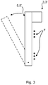
- Fig. 3 depicts a side view of any of the electrical switchgear devices 1,1' with the movable electrode arrangement 5, 5' in the closed position shown with solid lines, and with the movable electrode arrangement 4 in the open position shown with dashed lines.
- the flat coil 7 may be helical, i.e. a spiral coil, for example with a circular or essentially circular-shape, or square or essentially square-shaped.
- the electrical switchgear device may comprise an additional mechanical mechanism for normal opening of the contacts, i.e. to set the movable electrode arrangement in the open position, while the coil 7 is used only in case of fault or interruptions with very high currents.
- an additional mechanical mechanism for normal opening of the contacts i.e. to set the movable electrode arrangement in the open position, while the coil 7 is used only in case of fault or interruptions with very high currents.
- An example of a mechanism of this type is described in US6777635 .
- the electrical switchgear devices presented herein may beneficially be utilised in low voltage applications or medium voltage applications, wherein the electrical switchgear device may be a low voltage electrical switchgear device or a medium voltage switchgear device, respectively.
- the electrical switchgear devices disclosed herein may be utilised in both AC and DC applications.
- the electrical switchgear devices may by circuit breakers, such as air circuit breakers.
- both the fixed electrode arrangement and the movable electrode arrangement could comprise contact fingers.
Landscapes
- Gas-Insulated Switchgears (AREA)
- Driving Mechanisms And Operating Circuits Of Arc-Extinguishing High-Tension Switches (AREA)
- High-Tension Arc-Extinguishing Switches Without Spraying Means (AREA)
Description
- The present disclosure generally relates to electrical switchgear for fast limitation and interruption of fault currents. In particular it relates to a type of electrical switchgear which comprises a plurality of contact fingers arranged to divide current flowing through the electrical switchgear.
- Electrical switchgear devices may be used for breaking a fault current in a circuit in the event of a fault, in order to limit damages which may be caused due to the fault current. An electrical switchgear device may comprise a plurality of movable contact fingers which are thrown away at a fast speed from a fixed contact or electrode upon a tripping operation. The movable contact fingers are parallel connected when in mechanical connection with the fixed contact, thereby dividing the current in a number of components equal to the number of movable contact fingers. Larger currents may thereby be handled by the electrical switchgear device.
- In the event of a fast electric fault which creates a fault current of a large amplitude, it would generally be desirable to be able to trip the circuit as fast as possible.
US6777635 discloses a very high-speed limiting electrical switchgear apparatus which comprises a circuit for handling fast electric fault with currents of large amplitude. The switchgear apparatus comprises a coil which is connectable to a voltage source in the event of a fault, wherein a Thomson effect thruster is thrown away from the coil towards the contact fingers which as a result pivot clockwise, thus breaking the contact with fixed contacts, wherein a latch catches the contact fingers before they fall back into contact position. - Although the disclosure of
US6777635 provides fast tripping, it would still be desirable to provide an even faster and more robust electrical switchgear device. -
WO 2014/048483 A1 discloses an electrical switch with a Thomson coil drive. The device comprises two movable coils and two metal parts with the coils being arranged e.g. between the metal parts. Each coil is mechanically connected to the metal part on the opposite side and able to push the same away from the centre of the assembly. The two coils can be arranged electrically in parallel to each other. Upon application of a current pulse to the coils, the coils are attracted to each other due to their parallel magnetic fields, while the metal plates are accelerated outwards due to eddy currents. These two effects combine to separate the metal parts quickly. The metal parts thus move a respective actuator rod such that movable contacts move away from stationary contacts. -
EP 0147036 A1 discloses a circuit breaker assembly for breaking an alternating current path between terminals A and B. The circuit breaker assembly comprises a double break contact bridge movable from a contacting position to a circuit breaking position to provide a gap between the contact surfaces. A stub member connects the contact bridge to a substantially planar disc disposed between a substantially planar spiral coil. A source of current suitable for energising the coils is connected via switch and triac. By suitable arrangement of the switch and application of a pulse to the control terminal of the triac, it is possible to achieve a rapid opening or closing of the circuit breaker assembly. -
US 4 631508A discloses an electro-mechanical circuit breaker device incorporating a fuse cartridge. Two contact bars are normally connected by a series of mobile contacts held against their lower edge by springs, two in number for each. An insulating plate, suitably guided at its edges in the insulating envelope of the apparatus, receives the downward displacement that a coil applies by the Thomson effect to an aluminium disc, and it lowers the contacts against spring and latches them in open position by engagement of a bolt in a notch. The lower edge of the plate is provided with teeth to receive the successive contacts and retain them transversely, while each of the mobile contacts is notched to ensure lengthwise retention. - In view of the above an object of the present disclosure is thus to provide an electrical switchgear device which solves or at least mitigates the problems of the prior art.
- There is hence provided an electrical switchgear device comprising: a fixed electrode arrangement, a movable electrode arrangement having a contact portion and a repelling portion, wherein the movable electrode arrangement is arranged to move between a closed position in which the contact portion contacts the fixed electrode arrangement, and an open position in which the contact portion is mechanically separated from the fixed electrode arrangement, wherein one of the fixed electrode arrangement and the contact portion comprises a plurality of contact fingers which are all parallel connected when the movable electrode arrangement is in the closed position, and a coil which is fixed relative to the repelling portion, wherein the repelling portion is arranged adjacent to the coil to enable the coil to induce eddy currents in the repelling portion and wherein the coil and the fixed electrode arrangement are arranged on the same side of the movable electrode arrangement, and wherein the repelling portion is movable relative to the coil, wherein the coil has a first dimension between two of its opposite lateral ends, which first dimension corresponds to a majority of the distance between the two outermost contact fingers, and wherein the coil defines an area which corresponds to a majority of a surface area of the repelling portion, and wherein the repelling portion is adapted to provide a continuous current path, having a dimension corresponding to the first dimension of the coil, for eddy currents induced by the coil in the repelling portion.
- An effect which may be obtainable thereby is that a more robust electrical switchgear device may be provided. This is due to the fact that no additional actuator, such as the Thomson effect thruster in the prior art, is necessary for a breaking operation. The coil directly affects the movable electrode arrangement by induction of eddy current in the repelling portion, which thereby is thrown in a direction away from the coil due to the oppositely directed Lorentz forces. Since fewer mechanical components are utilised, fewer mechanical components will be subjected to the substantial wear due to the very high-power motion upon tripping. Furthermore, since there is a direct electromagnetic coupling between the coil and the movable electrode arrangement, tripping becomes faster than in the prior art where a coil induced a current in an actuator to throw the actuator towards the movable contacts in order to trip the circuit.
- According to one embodiment the coil is a flat coil defining a coil plane, wherein the repelling portion is arranged essentially in parallel with the coil plane when the movable electrode arrangement is in the closed position.
- According to one embodiment a width dimension of the repelling portion, which is a dimension between the two lateral ends of the repelling portion facing the flat coil, is at least as large as a corresponding width dimension of the fixed electrode portion.
- According to one embodiment the repelling portion defines a majority of the movable electrode arrangement, and wherein the area defined by the flat coil corresponds to a majority of the movable electrode arrangement.
- According to one embodiment the fixed electrode arrangement are the contact fingers, wherein the movable electrode arrangement is a plate.
- According to one embodiment the movable electrode arrangement are the contact fingers, wherein the fixed electrode arrangement is a plate.
- According to one embodiment the continuous current path is provided by flexible conducting elements which are connected to the two outermost contact fingers to provide a current path for eddy currents induced by the flat coil.
- According to one embodiment the flexible conducting elements are in electrical contact with all of the contact fingers.
- According to one embodiment the flat coil is helical.
- According to one embodiment the entire flat coil is arranged adjacent the repelling portion such that eddy currents induced in the repelling portion by the flat coil mirror a current flowing in the flat coil along the entire flow path of the current.
- According to one embodiment the area defined by the flat coil is defined by the boundary of the flat coil.
- According to one embodiment the flat coil is connectable to a voltage source in response to a fault.
- One embodiment comprises a structure which is fixed relative to the movable electrode arrangement, wherein the repelling portion is pivotally coupled to the structure to enable pivoting of the movable electrode arrangement between the closed position and the open position.
- According to one embodiment the electrical switchgear device is a low voltage electrical switchgear device or a medium voltage switchgear device.
- According to one embodiment the electrical switchgear device is an air circuit breaker.
- Generally, all terms used in the claims are to be interpreted according to their ordinary meaning in the technical field, unless explicitly defined otherwise herein. All references to "a/an/the element, apparatus, component, means, etc. are to be interpreted openly as referring to at least one instance of the element, apparatus, component, means, etc., unless explicitly stated otherwise.
- The specific embodiments of the inventive concept will now be described, by way of example, with reference to the accompanying drawings, in which:
-
Fig. 1a schematically depicts a front view of a first example of an electrical switchgear device; -
Fig. 1b depicts a top view of the electrical switchgear device inFig. 1a ; -
Fig. 2a schematically depicts a front view of a second example of an electrical switchgear device; -
Fig. 2b depicts a top view of the electrical switchgear device inFig. 2a ; and -
Fig. 3 schematically shows the operation of the electrical switchgear devices shown inFigs 1a and2a . - The inventive concept will now be described more fully hereinafter with reference to the accompanying drawings, in which exemplifying embodiments are shown. The inventive concept may, however, be embodied in many different forms and should not be construed as limited to the embodiments set forth herein; rather, these embodiments are provided by way of example so that this disclosure will be thorough and complete, and will fully convey the scope of the inventive concept to those skilled in the art. Like numbers refer to like elements throughout the description.
-
Fig. 1a depicts anelectrical switchgear device 1 in a simplified manner. In particular, only the electrode contacts which in a closed position are in mechanical contact with each other and in an open position are mechanically separated are shown. - The
electrical switchgear device 1 comprises a fixedelectrode arrangement 3, amovable electrode arrangement 5, and acoil 7. In the following, thecoil 7 will be exemplified by a flat coil although it is envisaged that a curved coil could be utilised instead, for example wound around an electromagnetic core. - The
movable electrode arrangement 5 has acontact portion 5f and a repellingportion 5e, and is movable relative to the fixedelectrode arrangement 3 and relative to theflat coil 7. Theflat coil 7 and the fixedelectrode arrangement 3 are arranged on the same side of themovable electrode arrangement 5 with thecontact portion 5f facing the fixedelectrode arrangement 3 and the repellingportion 5e facing theflat coil 7. - With a flat coil is meant a coil which is essentially a spiral coil, i.e. a helical coil, and/or a square-shaped coil, with the coil being wound in essentially a single plane, herein termed a coil plane. In
Fig. 1a theflat coil 7 is drawn with solid lines when visible and with dashed lines when hid behind themovable electrode arrangement 5. - According to the example depicted in
Fig. 1a , the fixedelectrode arrangement 3 is a plate, and themovable electrode arrangement 5 comprises a plurality ofcontact fingers 5a-5d. According to the example, four contact fingers are shown, but the number of contact fingers could of course vary and be fewer or more than what is exemplified inFig. 1a . Thecontact fingers 5a-5d are longitudinal bars, which may comprise a plurality of laminated electrically conducting pieces, or may be made of a solid electrically conducting material. The repellingportion 5e of themovable electrode arrangement 5 is arranged to electromagnetically interact with theflat coil 7, and thecontact portion 5f of themovable electrode arrangement 5 is arranged to be in contact with the fixedcontact arrangement 3. It should be noted that with a portion is according to the present example meant to include several parts which are not coupled mechanically, i.e. a set of corresponding portions of all of the contact fingers. These together form both the repelling portion and the contact portion. - The repelling
portion 5e has a continuous current path provided by means offlexible conducting elements outermost contact fingers flexible conducting elements contact fingers 5a-5d. Theflexible conducting elements outermost contact fingers flexible conducting elements contact fingers outermost contact fingers electrode portion 5f due to opposite Lorentz forces. Alternatively, the outermost contact fingers may be coupled mechanically with the innermost contact fingers. - The repelling portion may optionally according to a variation of the movable electrode arrangement comprise additional flexible conducting elements, arranged between the
flexible conducting elements outermost contact fingers flexible conducting elements portion 5e, which area is larger than an area defined by theflat coil 7 and facing the repellingportion 5e, typically an area bounded by the outermost turn of theflat coil 7. - According to the example in
Fig. 1a , the fixedelectrode arrangement 3 has a width dimension di which is large enough to enable all of thecontact fingers 5a-5d of thecontact portion 5f to be arranged in mechanical contact with the fixedelectrode arrangement 3 when the movable electrode arrangement is in a closed position. The width dimension d2 of thecontact portion 5f, from oneouter contact finger 5a to the otherouter contact finger 5d is hence typically as large as the width dimension di of the fixedelectrode arrangement 3. In the closed position thecontact fingers 5a-5e are parallel connected. Moreover, in the closed position current is able to flow between the fixedelectrode arrangement 3 and themovable electrode arrangement 5. - The
electrical switchgear device 1 further comprises a structure 9 which is fixed relative to themovable electrode arrangement 5, as shown inFig. 1b . In particular, themovable electrode arrangement 5 may be pivotally coupled to the structure 9. Themovable electrode arrangement 5 may hence pivot from the closed position to an open position in which themovable electrode arrangement 5 is mechanically separated from the fixedelectrode arrangement 3 to thereby break a current flowing through a circuit in which theelectrical switchgear device 1 may be connected. According to one variation the structure may actually be arranged to follow the opening movement of the movable electrode arrangement, especially if employing an additional mechanical mechanism which handles normal opening of the movable electrode arrangement, whereby the movable electrode arrangement is subjected to a translational and rotational motion upon a tripping operation which involves thecoil 7. - The
flat coil 7 has a first dimension d3, between two of its opposite lateral ends, which typically is smaller than the corresponding width dimension d2 of thecontact portion 5f. Theflat coil 3 defines a coil plane, which is a plane in which at least one of the turns of theflat coil 3 is arranged; for a spiral coil all of the turns may generally be arranged in the coil plane. Theflat coil 7 is arranged adjacent to the repellingportion 5e when themovable electrode arrangement 5 is in the closed position. In this position, the surfaces of the repellingportion 5e which face theflat coil 7 are essentially parallel with the coil plane. Furthermore, the majority of the area defined by the repellingportion 5e, which is bounded by the twooutermost contact fingers 5a and the two outermostflexible conducting elements flat coil 7, e.g. the area defined by the outermost turn of theflat coil 7. In this manner, an eddy current path in the repellingportion 5e, which covers as large an area as possible may be provided. The larger the area in which eddy currents may circulate, the large the Lorentz force, and thus the faster the tripping action. - The
flat coil 7 is connectable, for example by means of aswitch 11, such as a power electronics switch, to avoltage source 13, for example a charged capacitor. It should be noted that theswitch 11 and thevoltage source 13 may, but need not necessarily form part of theelectrical switchgear device 1; they may for example be external devices connectable to the electrical switchgear device. When a fault occurs, resulting in a fault current, theswitch 11 is closed such that thevoltage source 13 induces a current through theflat coil 7. Thus, when theswitch 11 is closed and a current is induced in theflat coil 7, eddy currents are induced in the continuous current path defined bycontact fingers 5a-5d and theflexible conducting elements flat coil 7, creating opposite Lorentz forces. Since theflat coil 7 is arranged on the same side of themovable electrode arrangement 5 as the fixedelectrode arrangement 3, the movable electrode arrangement is pivotally thrown in a direction away from theflat coil 7 and the fixedelectrode arrangement 3, thus providing a circuit trip.Fig. 1b shows a top view of theelectrical switchgear device 1 in an open state, in which themovable electrode arrangement 5 is arranged at a distance from the fixedelectrode arrangement 3 and is thus in the open position. Themovable electrode arrangement 5 is biased by means ofenergy accumulating members 15 such as springs, in order to ensure that all of thecontact fingers 5a-5d are in mechanical contact with the fixedelectrode arrangement 3 when in the closed position. The arrows show the directions in which themovable electrode arrangement 5 is able to move relative to the fixedelectrode arrangement 3. The electrical switchgear device may comprise a latch arranged to catch the movable electrode arrangement in the open position such that it does not bounce back into mechanical contact with the fixed electrode arrangement. - With reference to
Figs 2a and 2b , a second example of an electrical switchgear device will now be described. The electrical switchgear device 1' comprises a fixed electrode arrangement 3', a movable electrode arrangement 5', and aflat coil 7, arranged on the same side of the movable electrode arrangement 5' as the fixed electrode arrangement 3'. - According to the second example the fixed electrode arrangement 3' comprises a plurality of contact fingers 3'a-3'd. The movable electrode arrangement 5' is a plate. The electrical switchgear device 1' functions in a similar manner as
electrical switchgear device 1, except that the contact fingers now form part of the fixed electrode arrangement instead of the movable electrode arrangement. Furthermore, the fixed electrode arrangement 3' is now biased towards the movable electrode arrangement 5' by means ofenergy accumulating members 15. The dimensions of theflat coil 7 relative to the dimensions of the movable electrode arrangement 5', as described in the first example above, apply analogously also for the second example. - The movable electrode arrangement 5' has a contact portion 5'f arranged to mechanically contact the contact fingers 3'a-3'd, and a repelling portion 5'e which is arranged to electromagnetically interact with the
flat coil 7. The repelling portion 5'e provides a continuous surface facing theflat coil 7, which continuous surface has an area of which the majority overlaps with the area defined by theflat coil 7. Eddy currents may thereby be induced by theflat coil 7 in the repelling portion 5'e in a manner which enables the eddy currents to circulate around essentially the entire repelling portion 5'e, when theswitch 11 is set in the closed position, enabling the voltage source to provide a current through theflat coil 7. -
Fig. 3 depicts a side view of any of theelectrical switchgear devices 1,1' with themovable electrode arrangement 5, 5' in the closed position shown with solid lines, and with the movable electrode arrangement 4 in the open position shown with dashed lines. - In both examples, the
flat coil 7 may be helical, i.e. a spiral coil, for example with a circular or essentially circular-shape, or square or essentially square-shaped. - In either embodiment, the electrical switchgear device may comprise an additional mechanical mechanism for normal opening of the contacts, i.e. to set the movable electrode arrangement in the open position, while the
coil 7 is used only in case of fault or interruptions with very high currents. An example of a mechanism of this type is described inUS6777635 . - The electrical switchgear devices presented herein may beneficially be utilised in low voltage applications or medium voltage applications, wherein the electrical switchgear device may be a low voltage electrical switchgear device or a medium voltage switchgear device, respectively. The electrical switchgear devices disclosed herein may be utilised in both AC and DC applications. The electrical switchgear devices may by circuit breakers, such as air circuit breakers.
- The inventive concept has mainly been described above with reference to a few examples. However, as is readily appreciated by a person skilled in the art, other embodiments than the ones disclosed above are equally possible within the scope of the inventive concept, as defined by the appended claims. For example, according to one variation both the fixed electrode arrangement and the movable electrode arrangement could comprise contact fingers.
Claims (16)
- An electrical switchgear device (1; 1') comprising:a fixed electrode arrangement (3; 3'),a movable electrode arrangement (5; 5') having a contact portion (5f; 5'f) and a repelling portion (5e; 5'e), wherein the movable electrode arrangement (5; 5') is arranged to move between a closed position in which the contact portion (5f; 5'f) contacts the fixed electrode arrangement (3; 3'), and an open position in which the contact portion (5f; 5'f) is mechanically separated from the fixed electrode arrangement (3; 3'), anda coil (7), wherein the repelling portion (5e; 5'e) is arranged adjacent to the coil (7) to enable the coil (7) to induce eddy currents in the repelling portion (5e; 5'e),wherein the coil (7) has a first dimension (d3) between two of its opposite lateral ends, which first dimension (d3) corresponds to a majority of the distance between the two outermost contact fingers (5a, 5d; 3'a, 3'd), and wherein the coil (7) defines an area which corresponds to a majority of a surface area of the repelling portion (5e; 5'e), and wherein the repelling portion (5e; 5'e) is adapted to provide a continuous current path, having a dimension corresponding to the first dimension (d3) of the coil (7), for eddy currents induced by the coil (7) in the repelling portion (5e; 5'e), whereby the movable electrode arrangement (5; 5') is pivotally thrown in a direction away from the coil (7) and the fixed electrode arrangement (3; 3'), thus providing a circuit trip,characterised in that one of the fixed electrode arrangement (3; 3') and the contact portion (5f; 5'f) comprises a plurality of contact fingers (5a-5d; 3'a-3'd) which are all parallel connected when the movable electrode arrangement (5; 5') is in the closed position and the coil (7) and the fixed electrode arrangement (3; 3') are arranged on the same side of the movable electrode arrangement (5; 5'), and wherein the repelling portion (5e; 5e') is movable relative to the coil (7).
- The electrical switchgear device (1; 1') according to claim 1, wherein the coil (7) is a flat coil defining a coil plane, wherein the repelling portion (5e; 5'e) is arranged essentially in parallel with the coil plane when the movable electrode arrangement (5; 5') is in the closed position.
- The electrical switchgear device (1; 1') as claimed in claim 2, wherein a width dimension (d4) of the repelling portion (5e: 5'e), which is a dimension between the two lateral ends of the repelling portion facing the flat coil (7), is at least as large as a corresponding width dimension (d1) of the fixed electrode portion (3; 3').
- The electrical switchgear device (1; 1') as claimed in claim 2 or 3, wherein the repelling portion (5e; 5'e) defines a majority of the movable electrode arrangement (5; 5'), and wherein the area defined by the flat coil (7) corresponds to a majority of the movable electrode arrangement (5; 5').
- The electrical switchgear device (1') as claimed in any of the preceding claims, wherein the fixed electrode arrangement (3') are the contact fingers (3'a-3'd), wherein the movable electrode arrangement (5') is a plate.
- The electrical switchgear device (1) as claimed in any of claims 1-4, wherein the movable electrode arrangement (5) are the contact fingers (5a'5d), wherein the fixed electrode arrangement (3) is a plate.
- The electrical switchgear device (1) as claimed in claim 6, wherein the continuous current path is provided by flexible conducting elements (6a, 6b) which are connected to the two outermost contact fingers (5a, 5d) to provide a current path for eddy currents induced by the flat coil (7).
- The electrical switchgear device (1) as claimed in claim 7, wherein the flexible conducting elements (6a, 6b) are in electrical contact with all of the contact fingers (5a-5d).
- The electrical switchgear device (1; 1') as claimed in any of claims 2-8, wherein the flat coil (7) is helical.
- The electrical switchgear device (1; 1') as claimed in any of claim 2-9, wherein the flat coil (7) is essentially circular or essentially square-shaped.
- The electrical switchgear device (1; 1') as claimed in any of claims 2-10, wherein the entire flat coil (7) is arranged adjacent the repelling portion (5e; 5'e) such that eddy currents induced in the repelling portion (5e; 5'e) by the flat coil mirror a current flowing in the flat coil along the entire flow path of the current.
- The electrical switchgear device (1; 1') as claimed in any of the claims 2-11, wherein the area defined by the flat coil (7) is defined by the boundary of the flat coil (7).
- The electrical switchgear device (1; 1') as claimed in any of the preceding claims, wherein the coil (7) is connectable to a voltage source (13) in response to a fault.
- The electrical switchgear device (1; 1') as claimed in any of the preceding claims, comprising a structure (9) which is fixed relative to the movable electrode arrangement (5; 5'), wherein the repelling portion (5e; 5'e) is pivotally coupled to the structure (9) to enable pivoting of the movable electrode arrangement (5; 5') between the closed position and the open position.
- The electrical switchgear device (1; 1') as claimed in any of the preceding claims, wherein the electrical switchgear device (1; 1') is a low voltage electrical switchgear device or a medium voltage switchgear device.
- The electrical switchgear device (1; 1') as claimed in any of the preceding claims, wherein the electrical switchgear device (1; 1') is an air circuit breaker.
Applications Claiming Priority (1)
| Application Number | Priority Date | Filing Date | Title |
|---|---|---|---|
| PCT/EP2014/060176 WO2015176734A1 (en) | 2014-05-19 | 2014-05-19 | High speed limiting electrical switchgear device |
Publications (2)
| Publication Number | Publication Date |
|---|---|
| EP3146548A1 EP3146548A1 (en) | 2017-03-29 |
| EP3146548B1 true EP3146548B1 (en) | 2018-12-05 |
Family
ID=50732197
Family Applications (1)
| Application Number | Title | Priority Date | Filing Date |
|---|---|---|---|
| EP14724474.3A Active EP3146548B1 (en) | 2014-05-19 | 2014-05-19 | High speed limiting electrical switchgear device |
Country Status (5)
| Country | Link |
|---|---|
| US (1) | US9805888B2 (en) |
| EP (1) | EP3146548B1 (en) |
| CN (1) | CN106463283B (en) |
| ES (1) | ES2714102T3 (en) |
| WO (1) | WO2015176734A1 (en) |
Families Citing this family (2)
| Publication number | Priority date | Publication date | Assignee | Title |
|---|---|---|---|---|
| FR3076945B1 (en) * | 2018-01-12 | 2020-10-16 | Mersen France Sb Sas | ELECTRICAL CONTACTOR AND SEMICONDUCTOR CUTTING DEVICE INCLUDING SUCH A CONTACTOR |
| CN109243878B (en) * | 2018-09-14 | 2023-10-20 | 浙江现代电气有限公司 | Three-position opening and closing operating mechanism of change-over switch |
Family Cites Families (37)
| Publication number | Priority date | Publication date | Assignee | Title |
|---|---|---|---|---|
| GB553105A (en) | 1941-11-18 | 1943-05-07 | Johnson And Phillips Ltd | Improvements in or relating to electric circuit breakers |
| FR2185853B1 (en) * | 1972-05-26 | 1977-12-30 | Merlin Gerin | |
| FR2454174A1 (en) * | 1979-04-09 | 1980-11-07 | Merlin Gerin | CONTACTOR WITH FAST OPENING FAULT CONTROL |
| US4467301A (en) * | 1982-08-27 | 1984-08-21 | Essex Group, Inc. | Electric switch having enhanced fault current capability |
| GB2150352A (en) * | 1983-11-25 | 1985-06-26 | Electricity Council | Circuit breaker assembly |
| FR2570217B1 (en) | 1984-09-07 | 1988-05-27 | Ferraz & Cie Lucien | ELECTROMECHANICAL CIRCUIT BREAKER |
| SE461884B (en) * | 1988-09-14 | 1990-04-02 | Asea Brown Boveri | STROEMBEGRAENSARE |
| SE461557B (en) * | 1989-04-28 | 1990-02-26 | Asea Brown Boveri | CONTACT DEVICE FOR ELECTRICAL CONNECTORS |
| DE59009511D1 (en) | 1990-03-28 | 1995-09-14 | Siemens Ag | Quick switch. |
| DE59309583D1 (en) * | 1992-03-31 | 1999-06-24 | Ellenberger & Poensgen | Remote controllable circuit breaker |
| US5430420A (en) * | 1994-01-24 | 1995-07-04 | Eaton Corporation | Contact arrangement for a circuit breaker using magnetic attraction for high current trip |
| JP3321963B2 (en) * | 1994-02-22 | 2002-09-09 | 株式会社デンソー | Plunger type electromagnetic relay |
| US5952744A (en) * | 1996-03-28 | 1999-09-14 | Anoiad Corporation | Rotary-linear actuator |
| SE9602069D0 (en) | 1996-05-24 | 1996-05-24 | Asea Brown Boveri | Switchgear |
| US6066998A (en) * | 1996-09-12 | 2000-05-23 | Massachusetts Institute Of Technology | Magnetic actuator with long travel in one direction |
| US6013889A (en) * | 1997-06-02 | 2000-01-11 | Allen-Bradley Company, Llc | Method for retaining a movable contact in a circuit interrupter |
| SE9901627D0 (en) | 1999-05-03 | 1999-05-03 | Asea Brown Boveri | Switchgear |
| FR2837619B1 (en) | 2002-03-22 | 2004-06-25 | Schneider Electric Ind Sa | HIGH-SPEED LIMIT SWITCHING ELECTRICAL APPARATUS |
| US7777600B2 (en) * | 2004-05-20 | 2010-08-17 | Powerpath Technologies Llc | Eddy current inductive drive electromechanical liner actuator and switching arrangement |
| JP4473088B2 (en) * | 2004-10-07 | 2010-06-02 | オークマ株式会社 | Linear motor |
| EP1892739A1 (en) * | 2006-08-25 | 2008-02-27 | Siemens Aktiengesellschaft | An electromagnetic drive unit and an electromechanical switching device |
| US7671711B2 (en) * | 2006-10-31 | 2010-03-02 | Fuji Electric Fa Components & Systems Co., Ltd. | Linear actuator for circuit breaker remote operation device |
| DE102008005115A1 (en) * | 2008-01-14 | 2009-07-16 | Siemens Aktiengesellschaft | Switching device, in particular power switching device, with two series-connected switching contact pairs for interrupting a current path |
| EP2194555A1 (en) | 2008-12-04 | 2010-06-09 | Abb Ag | Actuator for an installation switching device |
| EP2251887B1 (en) * | 2009-05-15 | 2016-03-16 | Abb Ag | Electromagnetic trip device |
| JP5521852B2 (en) * | 2010-03-30 | 2014-06-18 | アンデン株式会社 | Electromagnetic relay |
| WO2011128516A1 (en) * | 2010-04-15 | 2011-10-20 | Schneider Elect4Ic Industries Sas | Electrical switching device having an ultrafast actuation mechanism and hybrid switch comprising such a device |
| JP5134657B2 (en) * | 2010-07-27 | 2013-01-30 | 富士電機機器制御株式会社 | Contact mechanism and electromagnetic contactor using the same |
| JP5385877B2 (en) * | 2010-08-31 | 2014-01-08 | 富士電機機器制御株式会社 | electromagnetic switch |
| KR101086908B1 (en) * | 2010-10-15 | 2011-11-25 | 엘에스산전 주식회사 | Electromagnetic switch |
| ITBG20100062A1 (en) * | 2010-11-17 | 2012-05-18 | Abb Spa | ELECTRIC SWITCHING DEVICE. |
| DE202011110140U1 (en) | 2011-07-09 | 2012-12-07 | Maschinenfabrik Reinhausen Gmbh | Switching element and on-load tap-changer with such a switching element |
| JP5585550B2 (en) * | 2011-07-18 | 2014-09-10 | アンデン株式会社 | relay |
| JP5838920B2 (en) * | 2011-07-18 | 2016-01-06 | アンデン株式会社 | relay |
| CN102751116B (en) * | 2012-07-19 | 2014-12-03 | 福州大学 | Quick electromagnetic repulsion mechanism based on fault current energy and change rate and application of quick electromagnetic repulsion mechanism |
| WO2014048483A1 (en) | 2012-09-28 | 2014-04-03 | Abb Technology Ag | Electrical switch with thomson coil drive |
| CN102881493B (en) * | 2012-10-13 | 2015-03-04 | 福州天宇电气股份有限公司 | Electromagnetic vortex repulsion quick arc extinguishing switch |
-
2014
- 2014-05-19 ES ES14724474T patent/ES2714102T3/en active Active
- 2014-05-19 EP EP14724474.3A patent/EP3146548B1/en active Active
- 2014-05-19 US US15/308,038 patent/US9805888B2/en active Active
- 2014-05-19 CN CN201480078646.XA patent/CN106463283B/en active Active
- 2014-05-19 WO PCT/EP2014/060176 patent/WO2015176734A1/en active Application Filing
Non-Patent Citations (1)
| Title |
|---|
| None * |
Also Published As
| Publication number | Publication date |
|---|---|
| WO2015176734A1 (en) | 2015-11-26 |
| US20170084410A1 (en) | 2017-03-23 |
| US9805888B2 (en) | 2017-10-31 |
| EP3146548A1 (en) | 2017-03-29 |
| ES2714102T3 (en) | 2019-05-27 |
| CN106463283A (en) | 2017-02-22 |
| CN106463283B (en) | 2018-12-21 |
Similar Documents
| Publication | Publication Date | Title |
|---|---|---|
| RU2338287C2 (en) | Hybride switch mechanism | |
| JP5041311B2 (en) | DC and AC drive contactors | |
| TWI343068B (en) | ||
| EP2463880A1 (en) | Direct current arc chamber, and bi-directinal direct current electrical switching apparatus employing the same | |
| CN105047482B (en) | Electric contactor and control method for delayed closing and opening of electric contactor | |
| CA2761830A1 (en) | Electromagnetic trip device | |
| US4077025A (en) | Current limiting circuit interrupter | |
| US11817258B2 (en) | Flexible thomson coil to shape force profile/multi-stage thomson coil | |
| KR100734607B1 (en) | An electrical coil module, an electrical coil comprising such modules, an actuation mechanism including such a coil and a circuit breaker comprising such an actuation mechanism | |
| EP3146548B1 (en) | High speed limiting electrical switchgear device | |
| JP2013242977A (en) | Switch | |
| CN107346715B (en) | Arc pushing device | |
| EP2779191B1 (en) | Trip actuator for switch of electric power circuit | |
| EP3144950B1 (en) | Method and device for cutting off an electric current with dynamic magnetic blow-out | |
| KR19980032645A (en) | Current switching device with whirlwind dissipation mechanism | |
| WO2014048483A1 (en) | Electrical switch with thomson coil drive | |
| US20180166245A1 (en) | Circuit breaker | |
| US4652707A (en) | Power switch | |
| EP2426690B1 (en) | Magnetic actuator for a circuit breaker arrangement | |
| US9748061B2 (en) | Switching device | |
| US20220351926A1 (en) | High Voltage High Current Arc Extinguishing Contactor | |
| EP3073501B1 (en) | Multipole lineal switch | |
| US11651916B2 (en) | Switching device or contactor with high arc extinguishing capabilities | |
| SU1198594A1 (en) | Short-circuiting switch | |
| EP2388793A1 (en) | Actuator, tripping device and switch |
Legal Events
| Date | Code | Title | Description |
|---|---|---|---|
| STAA | Information on the status of an ep patent application or granted ep patent |
Free format text: STATUS: THE INTERNATIONAL PUBLICATION HAS BEEN MADE |
|
| PUAI | Public reference made under article 153(3) epc to a published international application that has entered the european phase |
Free format text: ORIGINAL CODE: 0009012 |
|
| STAA | Information on the status of an ep patent application or granted ep patent |
Free format text: STATUS: REQUEST FOR EXAMINATION WAS MADE |
|
| 17P | Request for examination filed |
Effective date: 20161219 |
|
| AK | Designated contracting states |
Kind code of ref document: A1 Designated state(s): AL AT BE BG CH CY CZ DE DK EE ES FI FR GB GR HR HU IE IS IT LI LT LU LV MC MK MT NL NO PL PT RO RS SE SI SK SM TR |
|
| AX | Request for extension of the european patent |
Extension state: BA ME |
|
| DAX | Request for extension of the european patent (deleted) | ||
| GRAP | Despatch of communication of intention to grant a patent |
Free format text: ORIGINAL CODE: EPIDOSNIGR1 |
|
| STAA | Information on the status of an ep patent application or granted ep patent |
Free format text: STATUS: GRANT OF PATENT IS INTENDED |
|
| GRAJ | Information related to disapproval of communication of intention to grant by the applicant or resumption of examination proceedings by the epo deleted |
Free format text: ORIGINAL CODE: EPIDOSDIGR1 |
|
| STAA | Information on the status of an ep patent application or granted ep patent |
Free format text: STATUS: REQUEST FOR EXAMINATION WAS MADE |
|
| INTG | Intention to grant announced |
Effective date: 20180614 |
|
| GRAP | Despatch of communication of intention to grant a patent |
Free format text: ORIGINAL CODE: EPIDOSNIGR1 |
|
| STAA | Information on the status of an ep patent application or granted ep patent |
Free format text: STATUS: GRANT OF PATENT IS INTENDED |
|
| INTC | Intention to grant announced (deleted) | ||
| INTG | Intention to grant announced |
Effective date: 20180716 |
|
| GRAS | Grant fee paid |
Free format text: ORIGINAL CODE: EPIDOSNIGR3 |
|
| GRAA | (expected) grant |
Free format text: ORIGINAL CODE: 0009210 |
|
| STAA | Information on the status of an ep patent application or granted ep patent |
Free format text: STATUS: THE PATENT HAS BEEN GRANTED |
|
| AK | Designated contracting states |
Kind code of ref document: B1 Designated state(s): AL AT BE BG CH CY CZ DE DK EE ES FI FR GB GR HR HU IE IS IT LI LT LU LV MC MK MT NL NO PL PT RO RS SE SI SK SM TR |
|
| REG | Reference to a national code |
Ref country code: GB Ref legal event code: FG4D |
|
| REG | Reference to a national code |
Ref country code: CH Ref legal event code: EP |
|
| REG | Reference to a national code |
Ref country code: AT Ref legal event code: REF Ref document number: 1074088 Country of ref document: AT Kind code of ref document: T Effective date: 20181215 |
|
| REG | Reference to a national code |
Ref country code: IE Ref legal event code: FG4D |
|
| REG | Reference to a national code |
Ref country code: DE Ref legal event code: R096 Ref document number: 602014037391 Country of ref document: DE |
|
| REG | Reference to a national code |
Ref country code: SE Ref legal event code: TRGR |
|
| REG | Reference to a national code |
Ref country code: NL Ref legal event code: MP Effective date: 20181205 |
|
| REG | Reference to a national code |
Ref country code: AT Ref legal event code: MK05 Ref document number: 1074088 Country of ref document: AT Kind code of ref document: T Effective date: 20181205 |
|
| REG | Reference to a national code |
Ref country code: LT Ref legal event code: MG4D |
|
| PG25 | Lapsed in a contracting state [announced via postgrant information from national office to epo] |
Ref country code: LV Free format text: LAPSE BECAUSE OF FAILURE TO SUBMIT A TRANSLATION OF THE DESCRIPTION OR TO PAY THE FEE WITHIN THE PRESCRIBED TIME-LIMIT Effective date: 20181205 Ref country code: HR Free format text: LAPSE BECAUSE OF FAILURE TO SUBMIT A TRANSLATION OF THE DESCRIPTION OR TO PAY THE FEE WITHIN THE PRESCRIBED TIME-LIMIT Effective date: 20181205 Ref country code: AT Free format text: LAPSE BECAUSE OF FAILURE TO SUBMIT A TRANSLATION OF THE DESCRIPTION OR TO PAY THE FEE WITHIN THE PRESCRIBED TIME-LIMIT Effective date: 20181205 Ref country code: FI Free format text: LAPSE BECAUSE OF FAILURE TO SUBMIT A TRANSLATION OF THE DESCRIPTION OR TO PAY THE FEE WITHIN THE PRESCRIBED TIME-LIMIT Effective date: 20181205 Ref country code: NO Free format text: LAPSE BECAUSE OF FAILURE TO SUBMIT A TRANSLATION OF THE DESCRIPTION OR TO PAY THE FEE WITHIN THE PRESCRIBED TIME-LIMIT Effective date: 20190305 Ref country code: LT Free format text: LAPSE BECAUSE OF FAILURE TO SUBMIT A TRANSLATION OF THE DESCRIPTION OR TO PAY THE FEE WITHIN THE PRESCRIBED TIME-LIMIT Effective date: 20181205 Ref country code: BG Free format text: LAPSE BECAUSE OF FAILURE TO SUBMIT A TRANSLATION OF THE DESCRIPTION OR TO PAY THE FEE WITHIN THE PRESCRIBED TIME-LIMIT Effective date: 20190305 |
|
| REG | Reference to a national code |
Ref country code: ES Ref legal event code: FG2A Ref document number: 2714102 Country of ref document: ES Kind code of ref document: T3 Effective date: 20190527 |
|
| PG25 | Lapsed in a contracting state [announced via postgrant information from national office to epo] |
Ref country code: GR Free format text: LAPSE BECAUSE OF FAILURE TO SUBMIT A TRANSLATION OF THE DESCRIPTION OR TO PAY THE FEE WITHIN THE PRESCRIBED TIME-LIMIT Effective date: 20190306 Ref country code: RS Free format text: LAPSE BECAUSE OF FAILURE TO SUBMIT A TRANSLATION OF THE DESCRIPTION OR TO PAY THE FEE WITHIN THE PRESCRIBED TIME-LIMIT Effective date: 20181205 Ref country code: AL Free format text: LAPSE BECAUSE OF FAILURE TO SUBMIT A TRANSLATION OF THE DESCRIPTION OR TO PAY THE FEE WITHIN THE PRESCRIBED TIME-LIMIT Effective date: 20181205 |
|
| PG25 | Lapsed in a contracting state [announced via postgrant information from national office to epo] |
Ref country code: NL Free format text: LAPSE BECAUSE OF FAILURE TO SUBMIT A TRANSLATION OF THE DESCRIPTION OR TO PAY THE FEE WITHIN THE PRESCRIBED TIME-LIMIT Effective date: 20181205 |
|
| PG25 | Lapsed in a contracting state [announced via postgrant information from national office to epo] |
Ref country code: PL Free format text: LAPSE BECAUSE OF FAILURE TO SUBMIT A TRANSLATION OF THE DESCRIPTION OR TO PAY THE FEE WITHIN THE PRESCRIBED TIME-LIMIT Effective date: 20181205 Ref country code: PT Free format text: LAPSE BECAUSE OF FAILURE TO SUBMIT A TRANSLATION OF THE DESCRIPTION OR TO PAY THE FEE WITHIN THE PRESCRIBED TIME-LIMIT Effective date: 20190405 Ref country code: CZ Free format text: LAPSE BECAUSE OF FAILURE TO SUBMIT A TRANSLATION OF THE DESCRIPTION OR TO PAY THE FEE WITHIN THE PRESCRIBED TIME-LIMIT Effective date: 20181205 |
|
| PG25 | Lapsed in a contracting state [announced via postgrant information from national office to epo] |
Ref country code: RO Free format text: LAPSE BECAUSE OF FAILURE TO SUBMIT A TRANSLATION OF THE DESCRIPTION OR TO PAY THE FEE WITHIN THE PRESCRIBED TIME-LIMIT Effective date: 20181205 Ref country code: SK Free format text: LAPSE BECAUSE OF FAILURE TO SUBMIT A TRANSLATION OF THE DESCRIPTION OR TO PAY THE FEE WITHIN THE PRESCRIBED TIME-LIMIT Effective date: 20181205 Ref country code: SM Free format text: LAPSE BECAUSE OF FAILURE TO SUBMIT A TRANSLATION OF THE DESCRIPTION OR TO PAY THE FEE WITHIN THE PRESCRIBED TIME-LIMIT Effective date: 20181205 Ref country code: EE Free format text: LAPSE BECAUSE OF FAILURE TO SUBMIT A TRANSLATION OF THE DESCRIPTION OR TO PAY THE FEE WITHIN THE PRESCRIBED TIME-LIMIT Effective date: 20181205 Ref country code: IS Free format text: LAPSE BECAUSE OF FAILURE TO SUBMIT A TRANSLATION OF THE DESCRIPTION OR TO PAY THE FEE WITHIN THE PRESCRIBED TIME-LIMIT Effective date: 20190405 |
|
| REG | Reference to a national code |
Ref country code: DE Ref legal event code: R097 Ref document number: 602014037391 Country of ref document: DE |
|
| PLBE | No opposition filed within time limit |
Free format text: ORIGINAL CODE: 0009261 |
|
| STAA | Information on the status of an ep patent application or granted ep patent |
Free format text: STATUS: NO OPPOSITION FILED WITHIN TIME LIMIT |
|
| PG25 | Lapsed in a contracting state [announced via postgrant information from national office to epo] |
Ref country code: SI Free format text: LAPSE BECAUSE OF FAILURE TO SUBMIT A TRANSLATION OF THE DESCRIPTION OR TO PAY THE FEE WITHIN THE PRESCRIBED TIME-LIMIT Effective date: 20181205 Ref country code: DK Free format text: LAPSE BECAUSE OF FAILURE TO SUBMIT A TRANSLATION OF THE DESCRIPTION OR TO PAY THE FEE WITHIN THE PRESCRIBED TIME-LIMIT Effective date: 20181205 |
|
| 26N | No opposition filed |
Effective date: 20190906 |
|
| REG | Reference to a national code |
Ref country code: CH Ref legal event code: PL |
|
| PG25 | Lapsed in a contracting state [announced via postgrant information from national office to epo] |
Ref country code: MC Free format text: LAPSE BECAUSE OF FAILURE TO SUBMIT A TRANSLATION OF THE DESCRIPTION OR TO PAY THE FEE WITHIN THE PRESCRIBED TIME-LIMIT Effective date: 20181205 Ref country code: LI Free format text: LAPSE BECAUSE OF NON-PAYMENT OF DUE FEES Effective date: 20190531 Ref country code: CH Free format text: LAPSE BECAUSE OF NON-PAYMENT OF DUE FEES Effective date: 20190531 |
|
| REG | Reference to a national code |
Ref country code: BE Ref legal event code: MM Effective date: 20190531 |
|
| PG25 | Lapsed in a contracting state [announced via postgrant information from national office to epo] |
Ref country code: LU Free format text: LAPSE BECAUSE OF NON-PAYMENT OF DUE FEES Effective date: 20190519 |
|
| PG25 | Lapsed in a contracting state [announced via postgrant information from national office to epo] |
Ref country code: TR Free format text: LAPSE BECAUSE OF FAILURE TO SUBMIT A TRANSLATION OF THE DESCRIPTION OR TO PAY THE FEE WITHIN THE PRESCRIBED TIME-LIMIT Effective date: 20181205 |
|
| PG25 | Lapsed in a contracting state [announced via postgrant information from national office to epo] |
Ref country code: IE Free format text: LAPSE BECAUSE OF NON-PAYMENT OF DUE FEES Effective date: 20190519 |
|
| PG25 | Lapsed in a contracting state [announced via postgrant information from national office to epo] |
Ref country code: BE Free format text: LAPSE BECAUSE OF NON-PAYMENT OF DUE FEES Effective date: 20190531 |
|
| PG25 | Lapsed in a contracting state [announced via postgrant information from national office to epo] |
Ref country code: CY Free format text: LAPSE BECAUSE OF FAILURE TO SUBMIT A TRANSLATION OF THE DESCRIPTION OR TO PAY THE FEE WITHIN THE PRESCRIBED TIME-LIMIT Effective date: 20181205 |
|
| PG25 | Lapsed in a contracting state [announced via postgrant information from national office to epo] |
Ref country code: HU Free format text: LAPSE BECAUSE OF FAILURE TO SUBMIT A TRANSLATION OF THE DESCRIPTION OR TO PAY THE FEE WITHIN THE PRESCRIBED TIME-LIMIT; INVALID AB INITIO Effective date: 20140519 Ref country code: MT Free format text: LAPSE BECAUSE OF FAILURE TO SUBMIT A TRANSLATION OF THE DESCRIPTION OR TO PAY THE FEE WITHIN THE PRESCRIBED TIME-LIMIT Effective date: 20181205 |
|
| PG25 | Lapsed in a contracting state [announced via postgrant information from national office to epo] |
Ref country code: MK Free format text: LAPSE BECAUSE OF FAILURE TO SUBMIT A TRANSLATION OF THE DESCRIPTION OR TO PAY THE FEE WITHIN THE PRESCRIBED TIME-LIMIT Effective date: 20181205 |
|
| PGFP | Annual fee paid to national office [announced via postgrant information from national office to epo] |
Ref country code: IT Payment date: 20230526 Year of fee payment: 10 Ref country code: FR Payment date: 20230526 Year of fee payment: 10 Ref country code: DE Payment date: 20230519 Year of fee payment: 10 |
|
| PGFP | Annual fee paid to national office [announced via postgrant information from national office to epo] |
Ref country code: SE Payment date: 20230519 Year of fee payment: 10 |
|
| PGFP | Annual fee paid to national office [announced via postgrant information from national office to epo] |
Ref country code: GB Payment date: 20230524 Year of fee payment: 10 Ref country code: ES Payment date: 20230725 Year of fee payment: 10 |