EP3146471B1 - Amusement park element tracking system - Google Patents
Amusement park element tracking system Download PDFInfo
- Publication number
- EP3146471B1 EP3146471B1 EP15729284.8A EP15729284A EP3146471B1 EP 3146471 B1 EP3146471 B1 EP 3146471B1 EP 15729284 A EP15729284 A EP 15729284A EP 3146471 B1 EP3146471 B1 EP 3146471B1
- Authority
- EP
- European Patent Office
- Prior art keywords
- retro
- ride
- rider
- reflective markers
- seat
- Prior art date
- Legal status (The legal status is an assumption and is not a legal conclusion. Google has not performed a legal analysis and makes no representation as to the accuracy of the status listed.)
- Active
Links
Images


Classifications
-
- G—PHYSICS
- G06—COMPUTING; CALCULATING OR COUNTING
- G06V—IMAGE OR VIDEO RECOGNITION OR UNDERSTANDING
- G06V40/00—Recognition of biometric, human-related or animal-related patterns in image or video data
- G06V40/10—Human or animal bodies, e.g. vehicle occupants or pedestrians; Body parts, e.g. hands
- G06V40/103—Static body considered as a whole, e.g. static pedestrian or occupant recognition
-
- G—PHYSICS
- G01—MEASURING; TESTING
- G01S—RADIO DIRECTION-FINDING; RADIO NAVIGATION; DETERMINING DISTANCE OR VELOCITY BY USE OF RADIO WAVES; LOCATING OR PRESENCE-DETECTING BY USE OF THE REFLECTION OR RERADIATION OF RADIO WAVES; ANALOGOUS ARRANGEMENTS USING OTHER WAVES
- G01S1/00—Beacons or beacon systems transmitting signals having a characteristic or characteristics capable of being detected by non-directional receivers and defining directions, positions, or position lines fixed relatively to the beacon transmitters; Receivers co-operating therewith
- G01S1/02—Beacons or beacon systems transmitting signals having a characteristic or characteristics capable of being detected by non-directional receivers and defining directions, positions, or position lines fixed relatively to the beacon transmitters; Receivers co-operating therewith using radio waves
- G01S1/68—Marker, boundary, call-sign, or like beacons transmitting signals not carrying directional information
-
- A—HUMAN NECESSITIES
- A63—SPORTS; GAMES; AMUSEMENTS
- A63G—MERRY-GO-ROUNDS; SWINGS; ROCKING-HORSES; CHUTES; SWITCHBACKS; SIMILAR DEVICES FOR PUBLIC AMUSEMENT
- A63G7/00—Up-and-down hill tracks; Switchbacks
-
- G—PHYSICS
- G01—MEASURING; TESTING
- G01S—RADIO DIRECTION-FINDING; RADIO NAVIGATION; DETERMINING DISTANCE OR VELOCITY BY USE OF RADIO WAVES; LOCATING OR PRESENCE-DETECTING BY USE OF THE REFLECTION OR RERADIATION OF RADIO WAVES; ANALOGOUS ARRANGEMENTS USING OTHER WAVES
- G01S17/00—Systems using the reflection or reradiation of electromagnetic waves other than radio waves, e.g. lidar systems
- G01S17/02—Systems using the reflection of electromagnetic waves other than radio waves
- G01S17/06—Systems determining position data of a target
-
- G—PHYSICS
- G05—CONTROLLING; REGULATING
- G05B—CONTROL OR REGULATING SYSTEMS IN GENERAL; FUNCTIONAL ELEMENTS OF SUCH SYSTEMS; MONITORING OR TESTING ARRANGEMENTS FOR SUCH SYSTEMS OR ELEMENTS
- G05B15/00—Systems controlled by a computer
- G05B15/02—Systems controlled by a computer electric
-
- G—PHYSICS
- G06—COMPUTING; CALCULATING OR COUNTING
- G06V—IMAGE OR VIDEO RECOGNITION OR UNDERSTANDING
- G06V10/00—Arrangements for image or video recognition or understanding
- G06V10/20—Image preprocessing
- G06V10/24—Aligning, centring, orientation detection or correction of the image
- G06V10/245—Aligning, centring, orientation detection or correction of the image by locating a pattern; Special marks for positioning
-
- G—PHYSICS
- G06—COMPUTING; CALCULATING OR COUNTING
- G06V—IMAGE OR VIDEO RECOGNITION OR UNDERSTANDING
- G06V10/00—Arrangements for image or video recognition or understanding
- G06V10/40—Extraction of image or video features
- G06V10/60—Extraction of image or video features relating to illumination properties, e.g. using a reflectance or lighting model
-
- G—PHYSICS
- G06—COMPUTING; CALCULATING OR COUNTING
- G06V—IMAGE OR VIDEO RECOGNITION OR UNDERSTANDING
- G06V20/00—Scenes; Scene-specific elements
- G06V20/40—Scenes; Scene-specific elements in video content
- G06V20/48—Matching video sequences
-
- G—PHYSICS
- G06—COMPUTING; CALCULATING OR COUNTING
- G06V—IMAGE OR VIDEO RECOGNITION OR UNDERSTANDING
- G06V20/00—Scenes; Scene-specific elements
- G06V20/50—Context or environment of the image
- G06V20/52—Surveillance or monitoring of activities, e.g. for recognising suspicious objects
-
- G—PHYSICS
- G08—SIGNALLING
- G08B—SIGNALLING OR CALLING SYSTEMS; ORDER TELEGRAPHS; ALARM SYSTEMS
- G08B21/00—Alarms responsive to a single specified undesired or abnormal condition and not otherwise provided for
- G08B21/18—Status alarms
-
- G—PHYSICS
- G08—SIGNALLING
- G08B—SIGNALLING OR CALLING SYSTEMS; ORDER TELEGRAPHS; ALARM SYSTEMS
- G08B21/00—Alarms responsive to a single specified undesired or abnormal condition and not otherwise provided for
- G08B21/18—Status alarms
- G08B21/22—Status alarms responsive to presence or absence of persons
-
- G—PHYSICS
- G08—SIGNALLING
- G08G—TRAFFIC CONTROL SYSTEMS
- G08G1/00—Traffic control systems for road vehicles
- G08G1/07—Controlling traffic signals
- G08G1/08—Controlling traffic signals according to detected number or speed of vehicles
-
- G—PHYSICS
- G08—SIGNALLING
- G08G—TRAFFIC CONTROL SYSTEMS
- G08G1/00—Traffic control systems for road vehicles
- G08G1/14—Traffic control systems for road vehicles indicating individual free spaces in parking areas
- G08G1/141—Traffic control systems for road vehicles indicating individual free spaces in parking areas with means giving the indication of available parking spaces
- G08G1/142—Traffic control systems for road vehicles indicating individual free spaces in parking areas with means giving the indication of available parking spaces external to the vehicles
-
- B—PERFORMING OPERATIONS; TRANSPORTING
- B60—VEHICLES IN GENERAL
- B60R—VEHICLES, VEHICLE FITTINGS, OR VEHICLE PARTS, NOT OTHERWISE PROVIDED FOR
- B60R22/00—Safety belts or body harnesses in vehicles
- B60R22/48—Control systems, alarms, or interlock systems, for the correct application of the belt or harness
- B60R2022/4808—Sensing means arrangements therefor
- B60R2022/4816—Sensing means arrangements therefor for sensing locking of buckle
Description
- This application claims the benefit of
U.S. Provisional Application No. 62/001,551, filed May 21, 2014 - The present disclosure relates generally to the field of tracking systems and, more particularly, to methods and equipment used to enable tracking of elements in a variety of contexts in an amusement park through a dynamic signal to noise ratio tracking system.
- Tracking systems have been widely used to track motion, position, orientation, and distance, among other aspects, of objects in a wide variety of contexts. Such existing tracking systems generally include an emitter that emits electromagnetic energy and a detector configured to detect the electromagnetic energy, sometimes after it has been reflected off an object. It is now recognized that traditional tracking systems have certain disadvantages and that improved tracking systems are desired for use in a variety of contexts, including amusement park attractions, workplace monitoring, sports, fireworks displays, factory floor management, robotics, security systems, parking, and transportation, among others.
-
US2010208129 describes a system for capturing images of a plurality of subjects having a first subject placed a distance in front of a second subject, the system comprising: at least one camera; at least one light source; a control/processing model (CPM). - The present invention is as set out in the appended claims.
- These and other features, aspects, and advantages of the present disclosure will become better understood when the following detailed description of example embodiments is read with reference to the accompanying drawings in which like characters represent like parts throughout the drawings, wherein:
-
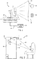
FIG. 1 is a schematic representation of a tracking system utilizing a dynamic signal to noise ratio device to track objects, in accordance with an embodiment of the present disclosure; -
FIG. 2 is a schematic representation of another tracking system utilizing a dynamic signal to noise ratio device to track objects, in accordance with an embodiment of the present disclosure; -
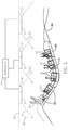
FIG. 3 is a schematic representation of an amusement park ride vehicle having retro-reflective markers and traveling through an enclosed area having the tracking system ofFIG. 1 , in accordance with an embodiment of the present disclosure; -
FIG. 4 is a schematic perspective view of a ride vehicle for an amusement park with the tracking system ofFIG. 1 for detecting whether a seat is occupied, in accordance with an embodiment of the present disclosure; -
FIG. 5 is a schematic perspective view of a seat for an amusement park attraction, the seat having retro-reflective markers for use with the tracking system ofFIG. 1 to track a position of a rider or seat feature, in accordance with an embodiment of the present disclosure; -
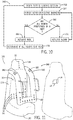
FIG. 6 is a schematic perspective view of a seat having a pattern of retro-reflective markers corresponding to an unoccupied seat, in accordance with an embodiment of the present disclosure; -
FIG. 7 is a schematic perspective view of the seat ofFIG. 6 having a pattern of retro-reflective markers corresponding to an occupied seat, in accordance with an embodiment of the present disclosure; -
FIG. 8 is a schematic perspective view of a seat having retro-reflective markers for use with the tracking system ofFIG. 1 to track a number of riders positioned within the seat, in accordance with an embodiment of the present disclosure; -
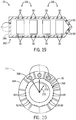
FIG. 9 is a schematic perspective view of a wearable item in the form of a wristband, the wristband having retro-reflective markers for use with the tracking system ofFIG. 1 to track a position of the rider, in accordance with an embodiment of the present disclosure; -
FIG. 10 is a process flow diagram of a method for determining a status of the seat via feedback from the tracking system, in accordance with an embodiment of the present disclosure; -
FIG. 11 is a schematic perspective view of an embodiment of the seat ofFIG. 5 having retro-reflective markers for use with the tracking system ofFIG. 1 to evaluate rider size, in accordance with an embodiment of the present disclosure; -
FIG. 12 is a process flow diagram of a method for determining a rider size via feedback from the tracking system, in accordance with an embodiment of the present disclosure; -
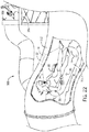
FIG. 13 is a side schematic representation of a child sitting in a ride vehicle that utilizes the tracking system ofFIG. 1 to confirm that the seat restraint is locked, in accordance with an embodiment of the present disclosure; -
FIG. 14 is a side schematic representation of an adult sitting in the ride vehicle that utilizes the tracking system ofFIG. 1 to determine that the seat restraint is not locked, in accordance with an embodiment of the present disclosure; -
FIG. 15 is a schematic perspective view of a ride restraint system having uncoupled connectors, the connectors having retro-reflective markers that reflect light at different wavelengths, in accordance with an embodiment of the present disclosure; -
FIG. 16 is a schematic perspective view of the ride restraint system ofFIG. 15 having coupled connectors, in accordance with an embodiment of the present disclosure; -
FIG. 17 is a schematic perspective view of a ride vehicle with the tracking system ofFIG. 1 used to detect that a ride door is not closed, in accordance with an embodiment of the present disclosure; -
FIG. 18 is a schematic perspective view of the ride vehicle ofFIG. 13 with the tracking system used to confirm that the ride door is closed, in accordance with an embodiment of the present disclosure; -
FIG. 19 is a schematic overhead view of the ride vehicle ofFIG. 4 , the ride vehicle having retro-reflective markers for use with the tracking system ofFIG. 1 to determine a boundary region; -
FIG. 20 is a schematic overhead view of a centrifugal amusement park ride having retro-reflective markers for use with the tracking system ofFIG. 1 to determine a boundary region; -
FIG. 21 is a process flow diagram of a method for controlling operation of an amusement park ride via feedback from the tracking system, in accordance with an embodiment of the present disclosure; and -
FIG. 22 is a schematic perspective view of a water park attraction utilizing the tracking system ofFIG. 1 to detect people using a device of the water park attraction, in accordance with an embodiment of the present disclosure. - Amusement parks include many rides that attract and entertain a large crowd of people. It is now recognized that it may be advantageous to include a tracking system on the rides to facilitate tracking and monitoring positions of people (e.g., riders), ride elements (e.g., ride restraints, ride boundaries, ride seat, ride vehicle, etc.), and objects before, during, and after operation of the ride. Tracking and monitoring riders on the ride may allow an operator of the ride to determine whether the ride is ready to be released from a loading section and/or ensure that the rider is following proper ride procedures. As one example, the tracking system may be used to track a number of riders that enter and exit the ride before and after each ride cycle (from ride start to ride finish). Additionally, the tracking system may be used to determine a status of a ride seat (e.g., occupied or unoccupied), evaluate a position of the rider and/or a position of a rider restraint (e.g., cross bar, harness, seat belt) relative to the ride seat, ride boundaries, and/or objects (e.g., backpack, hat, wallet). Accordingly, the tracking system may facilitate a flow of riders in and out of the ride in a reasonable amount of time, and thereby reduce ride wait times.
- In certain embodiments, the tracking system is designed to detect a relative positioning of an illuminated component (disposed on the ride, rider, or object) having a properly correlated retro-reflective material. The tracking system may utilize the relative positioning to monitor a position or existence of the rider and/or specific objects (e.g., the restraint, the ride seat, backpack, hat, wallet) or the ride within a field of view of the tracking system, and to activate an alarm or control operation of the ride. In one embodiment, if a proper correlation is found, the tracking system may provide an output to a computer, display, or monitoring device.
-
FIG. 1 is a schematic view of a dynamic signal to noise ratio tracking system 10 (hereinafter referred to as "tracking system 10") in accordance with present embodiments. Thetracking system 10 is designed to detect relative positioning of an illuminated component having a properly correlated retro-reflective material. As illustrated, thetracking system 10 includes anemitter 12, asensing device 14, acontroller 16, and an actuatable device 18 (e.g., a ride activation switch). Theemitter 12 operates to emit electromagnetic radiation, which is represented by an expandinglight beam 24 for illustrative purposes, to selectively illuminate, bathe or flood adetection area 26 in the electromagnetic radiation. Thelight beam 24 may be representative of multiple light beams being emitted from different sources. Further, in some embodiments thelight beam 24 is emitted at a frequency that has a correspondence to a material defining a retro-reflective marker 30 on anobject 32 located within the detection area. Indeed, in the illustrated embodiment, theobject 32 represents a component of a ride seat and the retro-reflective marker 30 represents a pattern of such marker. In certain embodiments, the retro-reflective marker 30 may be disposed on the ride (e.g., the ride seat). In other embodiments, the retro-reflective marker 30 may form part of a necklace, wristband, or button wearable by amusement park guests. - The retro-
reflective marker 30 may include a coating of retro-reflective material disposed on a body of theobject 32, or a solid piece of retro-reflective material coupled with the body of theobject 32. The retro-reflective marker 30 may coordinate with thelight beam 24 to reflect electromagnetic radiation back toward thesensing device 14 to facilitate identification of a location of the retro-reflective marker 30 by thesystem 10. This location information (obtained using the reflected electromagnetic radiation) may then be utilized by thecontroller 16 to determine whether theactuatable device 18 or a component of theactuatable device 18 should be actuated. In some embodiments, thelight beam 24 represents a limited number of light beams or light emissions (provided in series or simultaneously) that are used to identify the position of theobject 32, which may be facilitated by the retro-reflective marker 30. Indeed, the retro-reflective marker 30 may operate or be designed to always or essentially always return radiation (e.g., light) to its source. - Specifically, in operation, the
sensing device 14 of thesystem 10 may function to detect thelight beam 24 bouncing off of the retro-reflective marker 30 and provide data associated with the detection to thecontroller 16 via connections 40 (e.g., wired or wireless communication features) for processing. Thesensing device 14 may operate to specifically identify themarker 30 based on specific wavelengths of light emitted and reflected and, thus, avoid issues with false detections. In this regard, different types of retro-reflective markers 30 (e.g., having different colors) may also be distinguished from one another by thesystem 10. Also, such detection of the retro-reflective markers 30 may also facilitate pattern detection and disruption, as discussed in further detail below. Once thecontroller 16 receives the data from thesensing device 14, thecontroller 16 may utilize aprocessor 42 and/or a memory 44 to determine a location of the retro-reflective marker 30. Indeed, thecontroller 16 may employ known visual boundaries or an established orientation of the sensing device 14 (e.g., a priori information) to identify a location (e.g., coordinates) corresponding to the detected retro-reflective marker 30. These acts may be carried out, for example, using one or more processing devices of theprocessor 42 in combination with the memory 44, which may include one or more tangible, non-transitory, machine-readable media collectively storing instructions executable by theprocessor 42. - The
controller 16 may determine a change in reflected light intensity from the retro-reflective marker 30 or a change in a pattern of multiple retro-reflective markers 30. The memory 44 may store threshold values corresponding to a reflected light intensity profile or pattern associated with a status. For example, in certain embodiments, the retro-reflective marker 30 or a pattern ofmarkers 30 may be partially or completely blocked. As such, thecontroller 16 may determine that an object or rider is positioned over the retro-reflective marker 30. In this way, thetracking system 10 may track the position of the object or rider based on attenuation of the reflected light or changes in a detected pattern. - In accordance with certain embodiments of the present disclosure, the system 10 (e.g., using its associated components) may perform tracking of the
riders 94 and/or ride elements (e.g., their positions and positions relative to other ride features) based on the recognition of patterns, and the disruption of patterns formed by a plurality of the retro-reflective markers 30. For example, in a first ride configuration, the retro-reflective markers 30 may be present in a first pattern, which is recognized and monitored by thesystem 10. If the first ride configuration were associated with, for example, a vacant seat, then thesystem 10 may associate the first pattern with a vacant ride seat. However, if the first ride configuration were to change, then the change may result in a second pattern of the retro-reflective markers 30. In accordance with an embodiment, thesystem 10 is configured to detect the second pattern of the retro-reflective markers 30, associate the second pattern with the change, and perform certain actions (e.g., produce warnings, activate various ride mechanisms) as a result of this detection and association. For example, the first configuration may have been changed by a passenger sitting in the ride seat, resulting in all or a portion of the first pattern of the retro-reflective markers 30 being covered to produce the second pattern. In this example, thesystem 10 might associate the second pattern with an occupied ride seat. As described in further detail below, more sophisticated associations may be performed based on the type and degree of change in patterns of the retro-reflective markers 30. For example, if less than a threshold amount of the first pattern of the retro-reflective markers 30 is covered, then thesystem 10 might indicate that the occupant of the ride seat is too small for the ride, and not allow the ride to start until the ride seat is vacant or occupied by a person large enough to cover an appropriate amount of the first pattern (e.g., to produce an appropriate second pattern). These and other embodiments are described in further detail below. - In addition to or in lieu of tracking one or more of the retro-
reflective markers 30, thetracking system 10 may be configured to detect and track various other objects located within thedetection area 26. For example, thesensing device 14 of thesystem 10 may function to detect thelight beam 24 bouncing off of an object 50 (without retro-reflective markers 30) and provide data associated with this detection to thecontroller 16. That is, thesensing device 14 may detect theobject 50 based entirely on the reflection of electromagnetic energy off theobject 50. In some embodiments, theobject 50 may be coated with a particular coating that reflects thelight beam 24 in a detectable and predetermined manner. Once thecontroller 16 receives the data from thesensing device 14, thecontroller 16 may determine a location of theobject 50. Thecontroller 16 may be configured to identify certain objects that are expected to cross the path of thelight beam 24 within thedetection area 26, including thoseobjects 50 that are not marked with retro-reflective material.Such objects 50 may include, among other things, rides, ride restraints, people (e.g., riders), and rider's personal belongings (e.g., backpack, hat, wallet). - As may be appreciated based on the disclosure above, present embodiments of the
tracking system 10 may be configured to detect positions ofmultiple objects 50 and/or retro-reflective markers 30. That is, instead of being positioned and calibrated to determine the presence or position of only a single object (e.g., a single tracked object, a single detected object, a single object associated with a plurality of retro-reflective markers 30) in its field of view, thetracking system 10 is configured to detect and track multiple objects and/or markers located within the same detection area 26 (e.g., multiple patterns of retro-reflective markers 30, relative positions of different colors or shapes of retro-reflective markers 30). To that end, theemitter 12 is configured to flood thedetection area 26 with electromagnetic radiation (e.g., via the light beam 24), and thedetector 14 is configured to detect the reflected radiation that bounces back from one or more of theobjects 50 and/or retro-reflective markers 30 in thedetection area 26. Thus,fewer tracking systems 10 may be utilized to detect objects and/or multiple markers (e.g., multiple patterns of markers) within a given area. - As discussed above, the retro-
reflective markers 30 may represent a pattern of retro-reflective markers that reflect light from theemitter 12 and are detected by thedetector 14 of thetracking system 10. In the embodiment illustrated byFIG. 1 , theemitter 12 and the sensor orsensing device 14 are positioned adjacent to one another. In some embodiments, theemitter 12 and thesensing device 14 may have a concentric arrangement. For example, theemitter 12 may be surrounded bymultiple sensing devices 14 or the sensing device may be surrounded bymultiple emitters 14. In other embodiments, the sensing device 14 (e.g., an infrared camera) may be positioned in a different location with respect to theemitter 12, which may include an infrared light bulb. For example, as illustrated inFIG. 2 , theemitter 12 and thesensing device 14 are separate and positioned in different locations. Specifically, theemitter 12 ofFIG. 2 is positioned outside of an entrance 58 (e.g., a glass door) of an indoor amusement park attraction containing other components of thesystem 10. Thesensing device 14 ofFIG. 2 is positioned away from theemitter 12 but still oriented to detect light reflected from the retro-reflective marker 30 and originating from theemitter 12. For illustrative purposes,arrows detection area 26, reflected by the retro-reflective marker 30 on theobject 32, and detected by thesensing device 14. The light beam represented by thearrow 60 is merely one of numerous light beams that flood or otherwise selectively illuminate thedetection area 26 from theemitter 12. It should be noted that still other embodiments may utilize different arrangements of components of thesystem 10 and implementations in different environments in accordance with the present disclosure. - Having now discussed the general operation of the
tracking system 10 to detect a position of retro-reflective markers 30 and/or objects 50, as illustrated inFIGS. 1 and 2 , certain embodiments of thetracking system 10 will be described in detail. For example, it may be desirable to track the locations of people or objects within thedetection area 26 associated with the ride (e.g., a ride vehicle and/or a ride loading and unloading areas) through the use of the disclosed tracking systems. This may be useful, for example, for identifying occupied ride vehicles, rider and/or restraint position with respect to the rider seat, and how many riders entered and exited the ride at each ride cycle, among others. The presently disclosed trackingsystem 10 may be configured to identify and/or track the position and movement of the riders, objects belonging to the riders, portions of ride vehicles, or any combinations thereof, within thedetection area 26, for example by associating the riders and/or objects with one or more retro-reflective markers 30. Thetracking system 10 may accomplish this tracking in several different ways, which are described in detail below. It should be noted that thetracking system 10 may detect a position of one or more riders at a time in thesame detection area 26 using one or more of theemitter 12,sensing device 14, andcontroller 16. -
FIG. 3 illustrates an embodiment of an amusement park ride that may utilize thetracking system 10 in accordance with the present disclosure. In particular,FIG. 3 illustrates an embodiment of an indoor amusement park attraction 80 (herein after referred to as "ride 80") withmultiple ride vehicles 82 traveling along a ride path 84 (e.g., a track). In the illustrated embodiment, theemitters 12 andsensing devices 14 of thetracking system 10 are positioned on aceiling 90 of theride 80. In other embodiments, however, theemitters 12 andsensing devices 14 may be positioned along other stationary components of theride 80 facing toward theride path 84. Theride vehicles 82 may include retro-reflective markers 30 on the portions of theride vehicles 82 where the riders are supposed to sit. Although shown as one retro-reflective marker 30 per seat position, in other embodiments there may be an array of retro-reflective markers 30 corresponding to each individual seat. For example, the array may form a first pattern of markers identified by thecontroller 16. When arider 94 is present in a particular seat of theride vehicle 82, thetracking system 10 may detect a change in the array, for example a change of the first pattern resulting from blockage of certain retro-reflective markers 30 (e.g., thereby forming a second pattern), as discussed below with reference toFIG. 4 . Thetracking system 10 may also detect a decrease in reflected light intensity from the retro-reflective markers 30. For example, in certain embodiments, such as if all of the retro-reflective markers 30 are blocked, thetracking system 10 may not detect reflected light from the corresponding retro-reflective marker 30 or a subset or array ofmarkers 30. Accordingly, thecontroller 16 may indicate to an operator of theamusement attraction 80 that the particular ride seat is occupied or may perform some control action, such as enabling the ride to begin. Similarly, the retro-reflective markers 30 may be disposed along thetrack 84 to enable thecontroller 16 to determine that theride vehicle 82 is positioned over the corresponding portion of thetrack 84. - In other embodiments, the
tracking system 10 may detect changes in pattern of the retro-reflective markers 30 in a seat during operation to perform additional monitoring and control. For example, during operation of theamusement attraction 80, therider 94 may shift within the ride seat. As a result, a portion of the patterns of the retro-reflective marker 30 may be exposed at any given time during the duration of the ride. Therefore, in addition to monitoring the ridership of theride 80 before the start of the ride, thecontroller 16 may monitor the changing of the pattern of retro-reflective markers 30 associated with a particular ride seat to determine a degree of rider shifting within an occupied seat. As described in further detail below, thecontroller 16 may monitor this degree and may perform certain control actions based on the monitoring. For instance, thecontroller 16 may generate an alert for a ride operator that the rider is not properly seated, or is not adhering to appropriate ride protocols. Additionally or alternatively, thecontroller 16 may cause the ride to slow or stop altogether. If these determinations are performed before the ride has begun, thecontroller 16 may prevent theride 80 from initiating until a technician provides an "all-clear" or similar indication that the monitored activity does not present a problem. Further, if a particular ride seat is fitted with a large retro-reflective marker 30, thecontroller 30 may monitor the change in reflected light intensity (e.g., signal attenuation) to make similar determinations and perform similar control actions. For example, thecontroller 16 may determine whether a seat is occupied and whether the occupant is shifting beyond a degree that is appropriate. Further still, the degree of attenuation of the reflected light may correspond to a pattern of blocked and unblocked retro-reflective makers 30 indicative of an occupied seat. That is, in one embodiment, rather than monitoring distinct patterns, thecontroller 16 may monitor signal intensity and/or signal attenuation from one or more of the retro-reflective markers 30. - As an example, when the ride seats of
ride vehicles 82 are empty, the one or more retro-reflective markers 30 will be uncovered and able to reflect thelight beam 24 back to thesensing device 14 for detection via thetracking system 10. In this context, thetracking system 10 may be used to determine and keep an accurate count of the number ofriders 94 present on the particular ride 80 (e.g., based on the number of occupied seats). This may provide a more accurate count of the number ofriders 94 that actually participate in theride 80 than would be available through a person merely counting the people as they enter a ride loading area. In accordance with the determination of the ridership of particular attractions, thecontroller 16 of thetracking system 10 may maintain a log of the number ofriders 94 in eachride vehicle 82, or on all of theride vehicles 82 during a single pass (e.g., ride cycle) of theride 80, over the course of hours, days, weeks, months, or years. This ridership information may be accessible and used to generate reports and predictions relating to the popularity of theride 80. - As set forth above, in addition to determining ridership, the illustrated
tracking system 10 may be used to evaluate whether theriders 94 remain in their seats for the duration of theride 80. To enable substantially continuous monitoring of theride 80 during operation, the illustratedtracking system 10 includesmultiple emitters 12 andsensing devices 14 disposed along theceiling 90 and along a path of the ride 80 (e.g., generally along the track 84). Thesemultiple emitters 12 andsensing devices 14 may provide redundancy while monitoring the number and/or activity ofriders 94 present on theride vehicles 82. Somedetectors 14 may be better positioned to detect light reflected from certain seats of theride vehicles 82 than others. In some embodiments, themultiple emitters 12 andsensing devices 14 may be disposed at different angles throughout theride 80 to provide a redundant and, therefore, more accurate count and/or positions of theriders 94 currently on theride 80. The multiple sets ofemitters 12 andsensing devices 14 may be communicatively coupled to the same controller 16 (or a control network) for comparing the results from thedifferent sensing devices 14 and determining an accurate number ofriders 94. It should be noted that some embodiments may utilize asingle detector 14 positioned to observe an entire area. - While redundancy in the
emitters 12 andsensing devices 14 in theride 80 may be more accurate than a single emitter/sensing device pair for theentire ride 80, in certain embodiments, all or a portion of thetracking system 10 may be disposed on theride vehicle 82. That is, rather than attaching theemitter 12 and thesensing device 14 to theceiling 90, or another fixed position relative to theride vehicle 82, theemitter 12 and thesensing device 14 may be positioned on theride vehicle 82.FIG. 4 illustrates such an embodiment, where all or a portion of thetracking system 10 is integrated into theride vehicle 82. As shown, theemitter 12 andsensing device 14 of thetracking system 10 may be disposed in afront portion 100 of eachrow 102 in the ride vehicle 82 (e.g., facing toward where an occupant would be positioned while appropriately positioned in the ride vehicle 82). During operation, theemitter 12 may emit thelight beam 24 toward an array of retro-reflective markers 30 (e.g., a pattern) on aseat 108. If certain of the retro-reflective markers 30 (e.g., positioned on a lower portion of the seat 108) reflect the light back to thesensing device 14, thecontroller 16 may determine that theseat 108 is empty. However, if a rider is sitting in theseat 108, the rider may block all or some of the retro-reflective markers 30 from reflecting thelight beam 24 back to thesensing device 14. Thesensing device 14 may detect, as discussed in further detail below with respect toFIG. 6 , a change in the original pattern of the retro-reflective markers 30 (e.g., the pattern when the seat is not occupied), for example forming a changed pattern or no pattern of retro-reflective markers 30, or may detect a change in reflected light intensity from the retro-reflective markers 30, as discussed above with reference toFIG. 3 . As a result of detecting such a change, thecontroller 16 may determine that a rider is present in theseat 108. - Due to variability in rider size and shape, it may be desirable to use an array 110 (e.g., as a pattern) of retro-
reflective markers 30 disposed on theseat 108, so that thetracking system 10 can identify several points that are either covered or exposed to evaluate whether therider 94 is present. This may make the determination more robust than if only a single retro-reflective marker 30 were used. However, any desirable number of retro-reflective markers 30 in any pattern and/or position may be present on theseat 108 to aid in detection of a person occupying theseat 108 throughout the ride. - The
array 110 of retro-reflective markers 30 may also be particularly desirable on rides where some degree of rider movement is expected. That is, some rides with fast turns and lap bar restraints may allow theriders 94 to slide laterally within theseats 108 while still sufficiently restraining therider 94 within theseat 108. Thus, the larger surface area of thearray 110 of retro-reflective markers 30 may provide a useful indication that theriders 94 are still appropriately positioned in theseats 108. When therider 94 shifts in theseat 108, one or more of the retro-reflective markers 30 may become uncovered (e.g., a change from a first detected pattern to a second detected pattern occurs), causing them to reflect electromagnetic radiation back to thecorresponding sensing device 14. Thecontroller 16 may determine approximately how many of the retro-reflective markers 30 are exposed and compare this to a threshold number of retro-reflective markers 30 that are expected to be uncovered if a rider were to exit theride vehicle 82. As a more specific example, thecontroller 16 may determine a change in location and number of newly detected retro-reflective markers 30 resulting from rider movement, and make certain determinations and control actions as a result. In some embodiments, the threshold numbers or threshold changes in patterns may be determined between the number of retro-reflective markers 30 originally covered by therider 94 before the ride starts. - In one embodiment, the
controller 16 may monitor the specific pattern associated with a rider in a particular seat. That is, thecontroller 16 may determine that a certain number and location of retro-reflective markers 30 out of one or more rows and/or columns of a pattern of the retro-reflective markers 30 are covered by therider 94 before theride 80 begins. In other words, thecontroller 16 may associate a particular pattern with a particular rider (e.g., to produce an "associated pattern"). The associated pattern may correspond to a pattern of covered retro-reflective markers 30 (e.g., since thecontroller 16 will have a-priori information of the original pattern), a pattern of uncovered retro-reflective markers, or a combination thereof. - During operation of the
ride 80, thecontroller 16 may monitor changes in the associated pattern via changes in numbers and/or locations in these rows and columns (e.g., when certain retro-reflective markers 30 are uncovered and/or covered), and perform control actions when appropriate based on a degree of rider movement associated with the change. By monitoring these changes in the associated pattern as opposed to changes against only the original pattern (e.g., before the rider sits in the seat), thecontroller 16 may be able to account for variations in rider size and shape, thereby resulting in more accurate monitoring. - The
controller 16 may also associate different degrees of control and/or monitoring importance with different locations of the retro-reflective markers 30 within the associated pattern. For example, thecontroller 16 may associate a higher degree of control action and/or higher degree of monitoring importance with locations in the associated pattern where a change could potentially be indicative of a change in occupancy of the seat. Thecontroller 16 may implement such embodiments, for example, by only allowing small degrees of changes in the associated pattern at such locations. - As another example, the
controller 16 may use a reflected light intensity profile associated with the retro-reflective markers 30. In this way, thecontroller 16 may be able to distinguish between the reflection of a small number of retro-reflective markers 30 (or small portion of a single marker 30) that are exposed due to shifting in theseat 108 from a larger number of retro-reflective markers 30 (or larger portion of a single marker 30) that are exposed when therider 94 is not in theseat 108. In other embodiments, thecontroller 16 may make the determination that a rider has left theseat 108 when a certain number below a threshold number of the retro-reflective sensors 30 reflect light into thesensing device 14. The amount of shifting of therider 94 in theseat 108 may be quantified based on marker detection and utilized to control aspects of theride 80. For example, a specific rider may receive an automated communication regarding proper positioning prior to starting a ride. - As shown by way of example in
FIG. 4 , thearray 110 of retro-reflective markers 30 may be disposed in a lumbar region 114 (e.g., a lower region) of theseats 108. Thelumbar region 114 may generally refer to an area of a ride seat back section where a rider's lower back would be positioned. It may be expected that whenever a person is properly situated in theseat 108, thislumbar region 114 will generally be covered. Accordingly, if thelumbar region 114 becomes uncovered by therider 94, thecontroller 16 may determine that it is unlikely that therider 94 is appropriately positioned in theseat 108. If the status of one of theseats 108 changes (e.g., detecting a rider present in theseat 108 and then not detecting a rider in the seat 108) during the ride, thecontroller 16 of thetracking system 10 may send a signal to a control panel of theride 80 to stop theride 80 and/or to output an alert notifying the ride operators that a person is missing from theride vehicle 82. It should be noted that asingle tracking system 10 separate from theride vehicle 82 may also be used formultiple ride vehicles 82 and/or seats 108. - In some embodiments, the total number of retro-
reflective markers 30 disposed on theseat 108, the acceptable number of retro-reflective markers 30 that may be exposed without indicating a rider is out of theseat 108, and/or the position of the retro-reflective markers 30 disposed on theseat 108 may vary from ride to ride. These values may be different depending on the minimum height for riders that can ride in theride vehicle 82, the dynamics of the ride (e.g., fast, slow, jolting, smooth), and the manner in which the rider is restrained. That is, rides that are made for children and are relatively smooth may not include as many retro-reflective markers 30 as an adult ride that is rough and allows some shifting in theseats 108. - In accordance with present embodiments, the retro-
reflective markers 30 may be positioned along one or more parts of the seat 108 (e.g., a headrest, a restraint) including on thelumbar region 114.FIG. 5 illustrates an embodiment of theseat 108 having the retro-reflective markers 30 positioned in different locations, which may enable thecontroller 16 to perform additional restraint monitoring and control. In the illustrated embodiment, theseat 108 includes a base 120 where therider 94 may sit, aback section 124 to support the rider's back, aheadrest 126 to support the rider's head, and arestraint 130 configured to be lowered down across the rider's chest and lap to maintain the rider in theseat 108. However, it should be noted that other types, arrangements, sizes, and shapes ofseats 108 may be utilized withinother ride vehicles 82 in accordance with present embodiments. For example, the ride vehicle illustrated inFIG. 4 includes pairs ofseats 108 disposed side by side, these pairs ofseats 108 being arranged in therows 102 within asingle ride vehicle 82. In this type ofride vehicle 82, eachrow 102 may include asingle restraint bar 130 that lowers down over both riders in therow 102. - As illustrated in
FIG. 5 , theseat 108 includes thearray 110 of retro-reflective markers 30 in thelumbar region 114 of theback section 124 near or transitioning to theseat section 120. In this way, thetracking system 10 may accurately assess the status (e.g., occupied or unoccupied) of theseat 108. In some embodiments, therestraint 130 also includes the retro-reflective markers 30 to facilitate determining its position by theemitter 12 andsensing device 14, which may be separate or integral with theseat 108. In embodiments where thetracking system 10 is integral with theseat 108, theemitter 12 and thesensing device 14 may be positioned, for example, above theheadrest 126 of theseat 108 or in therestraint 130. - The
tracking system 10 may perform restraint monitoring using the retro-reflective markers 30 positioned at these different locations. For example, in certain embodiments, thecontroller 16 may monitor a pattern associated with the retro-reflective markers 30 in thelumbar region 114 against a pattern associated with the retro-reflective markers 30 on therestraint 130. In monitoring both patterns against each other, thecontroller 16 may monitor the proximity of therestraint 130 to thelumbar region 114, and therefore monitor whether therestraint 130 is in an appropriate position to restrain therider 94 during the ride. As non-limiting examples, thecontroller 16 may monitor an apparent size of themarkers 30 on therestraint 130 versus an apparent size of themarkers 30 on thelumbar region 114, may monitor differences in intensities between themarkers 30 on therestraint 130 andmarkers 30 on thelumbar region 114, may monitor a proximity of themarkers 30 on therestraint 130 andmarkers 30 on thelumbar region 114, and the like. As discussed in further detail below, the use of different colors (e.g., reflected wavelengths) may facilitate such monitoring. Further examples of the manner in which ridership and rider restraint may be monitored may be further appreciated with reference toFIGS. 6-12 and13-16 , respectively. - As discussed above, the
tracking system 10 may detect a change in a pattern of the retro-reflective markers 30 to determine ridership and/or rider movement during operation of theride 80.FIG. 6 illustrates an embodiment of theseat 108 having the retro-reflective markers 30 arranged in afirst pattern 136 on theback section 124. Certain features of theseat 108 have been omitted to facilitate discussion ofFIG. 6 , and it should be appreciated that the disclosed embodiments may be used in combination with any of the other embodiments disclosed herein as appropriate. The retro-reflective markers 30 may be arranged in any appropriate pattern, such as a grid, diamond, lines, circles, squares, or the like. Thefirst pattern 136 may include retro-reflective markers 30 spaced apart by a distance that allows therider 94 or ride objects (e.g., the ride restraint 130) to be detectable (e.g., inferentially by blocking one or more of the retro-reflective markers 30). Thecontroller 16 may identify thefirst pattern 136 and correlate theseat 108 with an unoccupied state. When therider 94 occupies theseat 108, one or more of the retro-reflective markers 30 are blocked.FIG. 7 illustrates an example of a second pattern 138 associated with one or more blocked retro-reflective markers 30 (as shown by the filled in circles). Thesensing device 14 may detect reflected light from the unblocked retro-reflective markers 30 (as shown by unfilled circles), and thecontroller 16 may identify the second pattern 138 as corresponding to anoccupied seat 108. For example, thecontroller 16 may perform a comparison of the detected light from the unblocked retro-reflective markers 30 in the second pattern 138 with stored positions of the retro-reflective markers 30 in thefirst pattern 136. - The
tracking system 10 may also be used to ensure an appropriate number of riders are seated in therow 102 of theride vehicle 82. For example, in certain amusement attractions, theride vehicle 82 includes a bench seat rather than individual seats, similar toseat 108. Unlike individual ride seats (e.g., the seat 108), bench seats generally accommodate several riders. However, at times, an undesirable number of riders may occupy the bench seat.FIG. 8 illustrates abench seat 144 that may use thetracking system 10 to determine the number ofriders 94 that occupy the bench seat. Similar to theseat 108, thebench seat 144 includes the retro-reflective markers 30 along a bench backsection 146. Before operation of theamusement attraction 80, thecontroller 16 may determine if the number ofriders 94 exceeds a rider limit for thebench seat 144. For example, when theriders 94 occupy thebench seat 144, theriders 94 may block a portion of the retro-reflective markers 30 (shown in phantom). Thesensing device 14 may detect a decrease in reflected light intensity due to blocked retro-reflective markers 30 or specifically detect that certain retro-reflective markers 30 are not visible (e.g., based on a change of the first pattern associated with an unblocked array of the retro-reflective markers 30). Thecontroller 16 may associate the decrease in reflected light intensity or missing retro-reflective markers 30 with a pattern of retro-reflective markers 30 that indicates the number ofriders 94 on thebench seat 146. If the number ofriders 94 exceeds a threshold value (stored in the memory 44), thecontroller 16 may send an output signal to the control panel for theride 80 that alerts the ride operator that thebench seat 146 has too many riders. Thecontroller 16 may provide a real-time feedback to the ride operator, for example, a running head count of the number ofriders 94 entering theride 80 and occupying thebench seat 146. In some embodiments, thecontroller 16 may send a no-go signal to the control panel of theride 80 so that theride 80 is not allowed to leave the station unless thebench seat 144 has a desirable number ofriders 94. Once the number ofriders 94 occupying thebench seat 146 is at or below the threshold value, thecontroller 16 may send a go signal to the control panel and theride 80 may leave the loading station. In certain embodiments, an override may be provided for use by the ride operator. - In certain embodiments, the
tracking system 10 may determine a status of theseat 108 or a position of therider 94 with respect to theride vehicle 82 using a wearable version of the retro-reflective marker 50. For example, at any time before theriders 94 enter the loading section of theride 80, eachrider 94 may be given a wearable retro-reflective marker (e.g., a wristband, a necklace, a button).FIG. 9 illustrates an embodiment of awristband 150 that may be used by thetracking system 10 to determine a location of therider 94 and a status of theseat 108. Thewristband 150 includes one or more wearable retro-reflective markers 152. The wearable retro-reflective markers 152 may be positioned on thewristband 100 in such a way that light reflected from the wearable retro-reflective markers 152 is detected by thesensing device 14. For example, as illustrated, the wearable retro-reflective markers 102 may be distributed around a circumference of thewristband 102. In this way, at least one of the wearable retro-reflective markers 102 may reflect thelight beam 24 when therider 94 is in the detection area. In certain embodiments, thewristband 150 may include a single retro-reflective marker 102 (e.g., a strip of retro-reflective material) that partially or completely wraps around thewristband 150. In other embodiments, thewristband 150 may be made entirely of the retro-reflective material. As an example, thecontroller 16 may monitor the retro-reflective markers 152 on the wristband 150 (or other wearable item) in relation to retro-reflective markers 30 on theseat 108 to establish rider occupancy, rider movement, and so forth. - In other embodiments, the wearable retro-
reflective markers 152 may be disposed on an object that belongs to therider 94. For example, therider 94 may place an adhesive dot or button that includes the wearable retro-reflective marker 152 onto their personal belongings such as, but not limited to, a backpack, purse, wallet, hat, glasses, or any other personal item. By placing the wearable retro-reflective marker 152 on the rider's items, these items may be located by thetracking system 10 in the event that the rider's items get lost or fall out of theride 80. - The retro-
reflective markers 30 and the wearable retro-reflective markers 152 may include different retro-reflective materials such that each retro-reflective marker light beam 24 differently (e.g., at a different wavelength, frequency, or angle). In this way, thetracking system 10 may use the retro-reflective markers seat 108 and a location of the rider 94 (or the rider's belongings) relative to theseat 108 and/or theride vehicle 82, as described in detail below with reference toFIG. 10 . Additionally, thetracking system 10 may track the rider's motion within the detection area. This may allow an operator of theride 80 to indentify riders that may be, for example, looking for anempty ride vehicle 82 to occupy. -
FIG. 10 illustrates a process flow diagram of amethod 160 of operating theride 80 that uses thetracking system 10 for tracking theriders 94 using the retro-reflective markers method 160 may be implemented as instructions stored in the memory 44 and that are executable by the one ormore processors 42 of thecontroller 16. In themethod 160, one ormore riders 94 enter the loading area of the ride 80 (step 162). The loading area may generally be within thedetection area 26 of thetracking system 10. - Following entrance of the
riders 94, themethod 160 includes detecting the retro-reflective markers ride 80 and/or theriders 94 with one or more of the sensing devices 14 (step 164). For example, during loading of theride 80, theriders 94 are positioned within the detection area 96. Accordingly, thesensing device 14 is able to detect light reflecting off of the wearable retro-reflective markers 152. Thecontroller 16 may monitor a movement of the wearable retro-reflective markers 152 as therider 94 moves towards theride vehicles 82. Before theriders 94 occupy theride vehicles 82, thesensing device 14 may also detect the retro-reflective marker 30 on theseat 108. Once theriders 94 have occupied theseat 108, thesensing device 14 may detect a change in an existing pattern of retro-reflective markers 30 on theseat 108, a decrease in reflected light intensity from the retro-reflective markers 30, or both. For example, as discussed above, therider 94 may block some or all of the retro-reflective markers 30 when they are positioned in theseat 108. As such, thesensing device 14 detects a change in a reflected light pattern from the retro-reflective markers 30. While this blocking of the retro-reflective markers 30 may be sufficient for occupancy detection, thesensing device 14 may also receive reflected light from the wearable retro-reflective markers 152, and use this for redundant occupancy detection, such as to limit the number of riders on theseat 108. Because the retro-reflective markers controller 16 may determine that theseat 108 is occupied by therider 94, and in some embodiments may determine the number ofriders 94 in theseat 108. - As discussed above, the
tracking system 10 may keep an accurate count of the number ofriders 94 present on theparticular ride 80. Accordingly, the illustratedmethod 160 also includes determining (query 166) if all theriders 94 that have entered the loading area of theamusement attraction 80 are positioned within theride vehicles 82. For example, theseats 108 having retro-reflective markers 30 with an attenuated (decrease in reflected light intensity) or a blocked signal should correspond to the number ofriders 94 within the detection area of theride 80. If all theriders 94 occupy a ride seat, thecontroller 16 may provide a signal to the control panel of the ride alerting the ride operator that all the countedriders 94 are positioned in one of theseats 108. - The
method 160 may also include actuation and release of theride 80 from the loading section (step 168). Theride 80 may be manually actuated by the ride operator or thecontroller 16 may send a go signal to the control panel for automatic actuation of theride 80. In contrast, if the number of occupied ride seats does not correspond to the number ofriders 94 detected in the loading area, thecontroller 16 may actuate an alarm or send a no-go signal to the control panel. Accordingly, theride 80 may not be released from the loading station and themethod 160 repeats until all theriders 94 occupy aseat 108 or an override is activated. - The
method 160 may also include determining (step 172) if all theriders 94 have exited theride 80 after each ride cycle. For example, once all theriders 94 have exited theride 80, thesensing device 14 may detect the original, non-blocked pattern of retro-reflective markers 30 in each of theseats 108. In certain embodiments, thesensing device 14 may detect an increase in reflected light intensity from the retro-reflective markers 30 and a decrease in reflected light intensity from the wearable retro-reflective markers 152. As a result, thecontroller 16 may determine that all theriders 94 have exited the unloading area of theride 80. Accordingly, thecontroller 16 may provide a signal to the operator that a following group ofriders 94 may load theamusement attraction 80 and themethod 160 repeats. - In addition to, or in lieu of, tracking the status of the ride seat and location of riders relative to ride vehicles, the
tracking system 10 may be used to determine if the rider meets ride size requirements. For example, in certain embodiments, theamusement attraction 80 may require theriders 94 to be a certain height. Generally, the rider's height is evaluated prior to entering the ride. However, the rider's height may be influenced by their footwear and/or posture during height measurement, and thereby result in inaccurate height assessment. In addition, due to rider size variability, it may be desirable to assess positioning of ride restraints relative to the rider even if the rider meets the height requirement for theride 80. -
FIG. 11 is an embodiment of theseat 108 including the retro-reflective markers 30 arranged such that the rider size may be assessed within theseat 108. In the illustrated embodiment, the retro-reflective markers 30 are positioned on theheadrest 126 and anupper region 180 of theseat 108. As should be noted, theheadrest 126 and theupper region 180 may include one retro-reflective marker 30 or an array of retro-reflective markers 30. In certain embodiments, the retro-reflective markers 30 on theheadrest 126 and theupper region 180 may be used instead of, or in addition to, the retro-reflective markers 30 in thelumbar region 114 to track seat status, as discussed above with reference toFIGS. 5-7 . In the illustrated embodiment, theemitter 12 and thesensing device 14 are positioned in front of the seat 108 (e.g., in another seat). However, in other embodiments, theemitter 12 and thesensing device 14 may be positioned in different locations (e.g., on theceiling 90 of the ride 80). In one embodiment, theseat 108 may include an indicator 182 (e.g., a light) that alerts the operator that therider 94 meets or does not meet the size requirements for theride 80. - In use, the
sensing device 14 may detect a decrease in reflected light intensity or detect reflected light from a specific set of retro-reflective markers 30 associated with a pattern of exposed retro-reflective markers 30 and retro-reflective markers 30 blocked by therider 94, as discussed above with reference toFIGS. 5-7 . Thecontroller 16 may use this information to determine whether or not therider 94 meets the ride size requirement.FIG. 12 is a process flow diagram of amethod 200 that includes operations performed by thecontroller 16 for rider size assessment using, for example, theseat 108 ofFIG. 11 . Similar to themethod 160, instructions for performing certain steps in themethod 200 may be stored as instructions in the memory 44 and are executable by the one ormore processors 42 of thecontroller 16. Instep 202 of themethod 200, therider 94 occupies theseat 108 of theride 80. Based on the size of therider 94, therider 94 may block one or more of the retro-reflective markers 30, for example a particular set of the retro-reflective markers 30. This may cause a certain pattern of retro-reflective markers 30 to illuminate and/or reflect light. In the context of height determination, the pattern associated with illuminated retro-reflective markers 30 in an upper region of theseat 108, such as at thehead rest 126, may be particularly important. - Accordingly, the
method 200 includes detecting the retro-reflective markers 30 on theheadrest 126 and theupper region 180, in step 204. As discussed above, thesensing device 14 may detect a change in pattern of the retro-reflective markers 30, sometimes as a decrease in reflected light intensity from the retro-reflective markers 30 or as identification of discrete points corresponding to markers forming a specific pattern. Consequently, thecontroller 16 may assess the size of therider 94 relative to theseat 108 based on the change in the pattern (e.g., reduction in number of illuminated/reflecting retro-reflective markers 30 in the headrest 126). - The
method 200 also includes determining (query 208) if therider 94 meets the size requirements for the particular ride. For example, if therider 94 blocks one or more retro-reflective markers 30 on theheadrest 126, thesensing device 14 may detect a smaller column of the retro-reflective markers 30 on theheadrest 126 ofFIG. 11 than was present before the rider sat in theseat 108. Thecontroller 16 may, for example, compare the detected pattern against stored patterns, compare the detected light intensity against stored light intensities, compare a detected number of retro-reflective markers against stored numbers of retro-reflective markers, and so forth, to determine a size of the rider. For example, thecontroller 16 may utilize a look-up table or similar data structure where light intensity, patterns, and/or numbers of retro-reflective markers 30 are associated with different rider heights and/or size profiles. However, in a general sense, thecontroller 16 may simply compare detected values associated with detected retro-reflective markers 30 against threshold values or ranges of values to make the determination ofquery 208. In this way, if the number or pattern of retro-reflective markers 30 indicates a person of an appropriate size, thecontroller 16 may determine that the ride can begin. - Therefore, if the
controller 16 determines that all riders are of an appropriate size, thecontroller 16 may actuate (step 212) a signal to start the ride. For example, in certain embodiments, thecontroller 16 may send a go signal to theindicator 182 or the control panel for the ride alerting the ride operator to start the ride, and the ride vehicle is allowed to leave the loading area. The indicator may display a first colored light (e.g., green) indicative of a suitable rider size. In certain embodiments, the control panel of the ride may display an alert associated with the go signal such that the ride operator may manually start the ride. In other embodiments, the go signal may automatically actuate the ride. As should be noted, a change in light intensity and/or pattern of retro-reflective makers 30 on both theheadrest 126 and theupper region 180 may need to be detected by thesensing device 14 for thecontroller 16 to actuate the go signal for the ride. - In contrast, if the
rider 94 does not meet the height requirement for theride 80, therider 94 will not block the retro-reflective markers 30 and thesensing device 14 does not detect any change in reflected light intensity and/or the change does not meet a desired threshold. Thecontroller 16 may determine that therider 94 does not meet the size requirement for the particular ride. As such, theindicator 182 may display a second colored light (e.g., red) indicative of an unmet rider size requirement. Therefore, instep 220, the ride does not start. For example, thecontroller 16 may send a no-go signal to the control panel of the ride so that the ride is not allowed to leave the loading area unless therider 94 is removed from the ride. In certain embodiments, the second colored light may be flashing to draw attention to the ride operator that therider 94 does not meet the size requirements. However, in other embodiments, the second colored light is continuous (e.g., non-flashing). Similarly, if the retro-reflective markers 30 on theupper region 180 of theseat 108 are unblocked by therider 94, the sensing device 14 (on therestraint 130 or the ceiling 90) may not detect a desirable change in pattern of the retro-reflective markers 30, and thecontroller 16 may actuate the no-go signal. For instance, in some embodiments, riders may be required to block certain retro-reflective markers 30 with their hands to allow a ride to begin and/or assess the rider's size. This may be required in conjunction with blocking of the retro-reflective markers 30 (e.g., with the rider's head) to get a go signal. - As set forth above, in addition to or in lieu of using retro-
reflective markers 30 to determine whether a rider is in theseat 108 or the rider has met a ride size requirement, embodiments of thetracking system 10 may be utilized to determine whether or not a rider is securely restrained in theride vehicle 82 prior to the start of the ride. Evaluating the restraints via theautomated tracking system 10 may increase the efficiency of loading theride vehicle 82, securing the riders in theirseats 108, and initiating the ride sequence. -
FIGS. 13 and 14 provide an example of one suchrestraint evaluation system 230 on theride vehicle 82. Therestraint evaluation system 230 includes alap bar restraint 232 in the illustrated embodiment, though it should be noted that in other embodiments, different types of restraints (e.g., pulled down from above the head such as the restraint 130) may be evaluated using similar systems. - The
restraint evaluation system 230 includes one or more retro-reflective markers 30 positioned on a surface (e.g., front portion 202) of theride vehicle 82. Therestraint evaluation system 230 is designed so that the retro-reflective markers 30 are completely covered when therestraint 232 is lowered from anupright position 234 into a locked position, as shown inFIG. 13 . In the illustrated embodiment, for example, therestraint 232 may include anextension 236 that is configured to cover the retro-reflective markers 30 when therestraint 232 is secured in the locked position (or, more generally, an appropriate restraint position). In the illustrated embodiment, theride vehicle 82 includes theemitter 12 angled such that the emittedlight beam 24 will hit the retro-reflective markers 30 if therestraint 232 is not fully lowered into the locked position, enabling themarkers 30 to reflect the light back toward thesensing device 14, as shown byarrow 238 inFIG. 14 . In the illustrated embodiment, theemitter 12 is positioned along alower portion 240 of theride vehicle 82. In other embodiments, theemitter 12 and/orsensing device 14 may be mounted in other places, such as on a ride loading area alongside theride vehicle 82. Thesensing device 14 sends asignal 242 indicative of the presence or absence of reflected electromagnetic radiation to thecontroller 16, which may provide an indication to a ride operator that therestraint 232 is either secured or unsecured. In some embodiments, thecontroller 16 may send a go/no-go signal to a control panel of the ride so that the ride is not allowed to leave the station unless all of therestraints 232 are in the proper locked position, according to therestraint evaluation system 230. - In addition to tracking the
riders 94, ride elements, or other objects associated with theride 80 based on light intensity and/or pattern changes of the retro-reflective markers 30, present embodiments also include tracking positions of theriders 94 and/or ride elements based on color recognition of the retro-reflective markers 30. For example, in certain embodiments, the retro-reflective markers 30 may include sets of one or more markers, where each set (e.g., forming its own pattern or as individuals) reflect light at a different wavelength that corresponds to a color (e.g., red, orange, yellow, green, blue, violet). For example, the retro-reflective markers 30 may reflect a wavelength within the visible spectrum range such as between approximately 380 nm to 750 nm. However, the different wavelengths may be within any suitable wavelength range within the electromagnetic spectrum. Because the retro-reflective markers 30 may reflect light at a different wavelength, in a simple scenario, thetracking system 10 may determine a position of one retro-reflective marker 30 relative to a second retro-reflective marker 30. This may be advantageous is determining proper positioning of theriders 94 and/or ride elements (e.g., ride restraint systems that are separate pieces, but may need to be attached during operation of the ride). -
FIGS. 15 and 16 illustrate an embodiment of therestraint 130 that may utilize retro-reflective markers 30 that reflect light at different wavelengths. Therestraint 130 includes abelt 244 having a male connector 246 (e.g., a fastener, hook) and a female connector 248 (e.g., a buckle). Themale connector 246 includes one or more of the retro-reflective markers 30 that reflect light at a first wavelength and thefemale connector 248 includes one or more of the retro-reflective markers 30 that reflect light at a second wavelength different from the first. Prior to therider 94 occupying theride seat 108, theconnectors reflective markers 30 on theconnector 246 are separated by a distance α from the retro-reflective markers 30 on theconnector 248. Thecontroller 16 may identify the distance α between the retro-reflective markers 30 on therespective connector - Once the
rider 94 occupies theseat 108, thetracking system 10 may monitor the distance α between the retro-reflective markers 30 on theconnectors connectors controller 16 may determine when theconnectors FIG. 16 illustrates theconnectors reflective markers 30 decreases when theconnectors controller 16 may determine a change in the distance α (e.g., Δα) between theconnectors controller 16 may indicate to the ride operator that theconnectors controller 16 may send a go/no-go signal to the ride control panel based on the distance α. For example, if thecontroller 16 determines that the change in the distance α corresponds to coupledconnectors controller 16 may send a go signal to the ride control panel to release theride vehicle 82 from the loading station. Thetracking system 10 may monitor the distance d between the retro-reflective markers 30 on theconnectors ride 80. Accordingly, if the distance d between the retro-reflective markers 30 of coupledconnectors controller 16 may alert the rider operator that theconnectors - Other types of restraint evaluation may be provided by the
tracking system 10. For example, in certain embodiments, therestraint evaluation system 230 may be used to determine whether a ride door is properly secured.FIG. 17 is an embodiment of theride vehicle 82 having adoor 250 designed to secure therider 94 in theride vehicle 82. In the illustrated embodiment, theride vehicle 82 includes the retro-reflective markers 30 at aninterface 252 between aride wall 254 and adoor wall 256. Alternatively, the retro-reflective markers 30 may be positioned on thedoor wall 256. During operation, therestraint evaluation system 230 may evaluate the status of the ride door 250 (e.g., open or closed) by detecting a change in light reflected from the retro-reflective markers 30 (e.g., corresponding to movement of themarkers 30 and covering of the markers 30). That is, if theride door 250 is closed, as illustrated inFIG. 18 , thedoor wall 256 blocks the retro-reflective markers 30 on theride wall 254, and thesensing device 14 detects a change in the reflected light (e.g., a decrease in reflected light intensity) or may not detect any reflected light. The decrease in reflected light intensity may indicate that theride door 250 is closed, and the ride may be allowed to leave the loading station. - In other embodiments, the
tracking system 10 may be used to ensure theriders 94 remain within a boundary region of theride 80. This may be beneficial in ensuring that theriders 94 remain properly positioned and follow proper ride procedures throughout the duration of the ride cycle. The amusement attraction may include retro-reflective markers 30 around a perimeter of the boundary region. For example,FIG. 19 is an overhead schematic view of an embodiment of theride vehicle 82 that includes aboundary region 262. In certain embodiments, theboundary region 262 may be around anouter perimeter 264 of the ride that may be detected by thetracking system 10. In other embodiments, theboundary region 262 may extend a certain distance away from theouter perimeter 264, as shown with reference toFIG. 19 . Specifically, for example, theboundary region 262 may be defined relative to the detected location of the retro-reflective markers 30. During operation of the ride, therider 94 may be advised to remain within theboundary region 262. As an example illustrated inFIG. 20 , when a rider crosses into theboundary region 262, thesensing device 14 may detect a change in reflected light intensity. Accordingly, thecontroller 16 may provide control signals to the control panel of the ride that may provide instructions to stop the ride provide a warning signal (e.g., visual and/or audible alarm). In certain embodiments, thetracking system 10 may detect the wearable retro-reflective markers 152 on thewristband 150 worn by therider 94 to determine whether therider 94 crossed theboundary region 262 or if the change in reflected light intensity from the retro-reflective markers 30 in theboundary region 262 was due to an anomaly. -
FIG. 20 illustrates an overhead schematic of acentrifugal amusement attraction 266 that may also utilize theboundary region 262 to ensure that the rider remains in a predetermined location of the ride. While in thecentrifugal amusement attraction 266, therider 94 is positioned within anarea 268 between theboundary region 262 and theouter perimeter 264. During operation of thecentrifugal amusement attraction 266, acentrifugal force 270 pushes therider 94 against theouter perimeter 264 and away from theboundary region 262. However, if the centrifugal force is less than desired, as indicated byarrow 272, therider 94 may move towards theboundary region 262. Therefore, if therider 94 crosses into theboundary region 262, thecontroller 16 may instruct the ride, or an operator of the ride, to adjust a rotational speed of the ride to increase the centrifugal force or stop the ride. Detection of this may be achieved by providing an array of retro-reflective markers 30 on a platform occupied by a rider. By detecting which retro-reflective markers 30 are visible, the rider's location on the platform can be monitored. -
FIG. 21 illustrates a process flow diagram of amethod 280 for evaluating a position of a rider of thecentrifugal amusement attraction 266 relative to theboundary regions 262 illustrated and described with reference toFIGS. 19 and 20 . Similar to themethods method 280 may include steps that are stored as instructions in the memory 44 and that are executable by one ormore processors 42 of thecontroller 16. It should be noted that in some embodiments, steps of themethod 280 may be performed in different orders than those shown, or omitted altogether. In addition, some of the blocks illustrated may be performed in combination with each other. - In the illustrated embodiment, the
method 280 includes determining a location of therider 94 based on a position of the reflected electromagnetic radiation received by thesensing device 14 of thetracking system 10, instep 282. Again, this position may be determined based on a detection of electromagnetic radiation reflected from retro-reflective markers 30 disposed in an area generally occupied by the rider 94 (e.g., theseat 108,bench seat 144, area 266) and/or the wearable retro-reflective markers 152. - The
method 280 also includes detecting a boundary (e.g., the boundary region 262) to the ride, instep 284. For example, thesensing device 14 may detect theretroreflected markers 30 around the perimeter of theboundary region 262 associated with theride 80. Using the detected reflected light, thecontroller 16 may determine a pattern of the retro-reflective markers 30. Thecontroller 16 may compare the pattern of the detected retro-reflective markers 30 with a predetermined pattern corresponding to theboundary region 262. - In
step 286, thecontroller 16 determines a proximity of therider 94 to the boundary. In an embodiment, thecontroller 16 may monitor a pattern of the retro-reflective markers 30, and monitor changes to this pattern that may be an indication that a rider has entered a region of theride 80 that is generally undesirable (e.g., the boundary region 262). As another example, in certain embodiments, therider 94 may use the wearable retro-reflective marker 152 during operation of thecentrifugal amusement attraction 266. Thecontroller 16 may determine a distance between the retro-reflective markers 30 associated with theboundary region 262 and the wearable retro-reflective marker 152 on therider 94. Using the distance between the retro-reflective markers controller 16 may determine the proximity of therider 94 to theboundary region 262. In still further embodiments, thecontroller 16 may determine a change in reflected light intensity from the retro-reflective markers 30 at theboundary region 262. For example, as therider 94 approaches theboundary region 262, the reflected light intensity from the retro-reflective markers 30 may decrease. - In addition, the
method 280 includes comparing the determined proximity with a predetermined threshold value instep 288. That is, thecontroller 16 may determine a pattern change or reflected light intensity profile associated with the retro-reflective markers 30 or a distance relationship between retro-reflective markers - If the determined proximity is less than or equal to the threshold value, the
method 280 includes adjusting (step 290) an operational parameter of the ride. As discussed above, thecontroller 16 of thetracking system 10 may send a control signal to a control panel of the ride to actuate this adjustment and/or stop the ride. If the determined proximity is greater than the threshold, however, no change is made and themethod 280 repeats. - The present disclosure may also be applicable to rides that are used outdoors (e.g., even in sunlight), such as water-based rides. For example, present embodiments of the
tracking system 10 may use light reflection techniques to provide zone control assistance on the water-based rides. For example,FIG. 22 illustrates awaterslide 300 that is at least partially enclosed within atube 302. Once someone enters thewaterslide 300 from anelevated platform 304, it may be difficult for the lifeguard at the top of theelevated platform 304 to determine when it is time for the next rider to go down thewaterslide 300. Incertain waterslides 300, the lifeguard may need to wait until the rider emerges from theenclosed tube 302 at the end of thewaterslide 300 to ensure that the rider is moving through thetube 302 as desired and that enough time has passed for another rider to enter. Using thetracking system 10, however, it may be possible to minimize the amount of time between each rider entering thewaterslide 300 from theelevated platform 304. To that end, thetube 302 may be equipped at one or more points along the length of thewaterslide 300 with one or more of theemitters 12 andsensing devices 14. Thewaterslide 300 may also include a waterslide seat (e.g., a mat, an inflatable tube). Thewater slide seat 306 may include one or more of the retro-reflective markers 30. Thesensing device 14 may detect riders as they pass through thewaterslide 300. This detection may be made based on the expected signature of thelight beam 24 reflecting off the rider going past, or based on light reflected off retro-reflective markers 30 disposed on atube 306. Thesensing device 14 may communicate (e.g., wirelessly) with thecontroller 16 of thetracking system 10 and thecontroller 16 may provide a control signal to theactuatable device 18. In this case, theactuatable device 18 may include a light 308, or other visual indicator, on theelevated platform 304 configured to indicate that thetracking system 10 has determined that the previous rider is passing thesensing device 14 in thewaterslide 300. This light 308 signals the lifeguard to send the next rider down thewaterslide 300, thus increasing the efficiency of operation of thewaterslide 300. - Similar to the embodiments discussed above with reference to
FIGS. 5-7 , thetracking system 10 may monitor a position of the rider with respect to thewaterslide seat 306. For example, based on an intensity change of reflected light or a pattern of unblocked retro-reflective markers 30, thetracking system 10 may determine if the rider is separated from thewaterslide seat 306 while in thetube 302. - While only certain features of the present embodiments have been illustrated and described herein, many modifications and changes will occur to those skilled in the art. It is, therefore, to be understood that the appended claims are intended to cover all such modifications and changes as fall within scope defined by the appended claims.
Claims (15)
- A system for providing a status of a rider in an amusement park ride comprising:a plurality of retro-reflective markers (30) positioned within an amusement park ride system;a tracking system (10) configured to detect the plurality of retro-reflective markers (30) to track a position and determine a status of a rider, within a ride seat (108) of the ride system, wherein the tracking system (10) comprises:an emitter (12) configured to emit light toward the plurality of retro-reflective markers (30);a detector (14) configured to detect reflected light from the plurality of retro-reflective markers (30); anda controller (16) configured to determine the position of the rider (94) relative to the plurality of retro-reflective markers (30) using the detection of the reflected light, and wherein the controller (16) is configured to provide an indication of the status of the rider (94), wherein the status of the rider (94) is whether the rider is restrained within the ride seat (108).
- The system of claim 1, wherein the ride system is configured to adjust an operational parameter of the ride system based on the position of the rider (94).
- The system of claim 1, wherein the ride system is configured to actuate an audible or visual alert via an interface communicatively coupled to the controller (16) based on the status of the rider (94).
- The system of claim 1, wherein the controller (16) is configured to determine the status of the rider based on a change in reflected light intensity from the plurality of retro-reflective markers (30).
- The system of claim 1, wherein the controller (16) is configured to associate a decrease in the reflected light intensity with the rider (94) blocking at least one of the plurality of retro-reflective markers (30).
- The system of claim 1, wherein the ride seat (108) comprises at least a portion of the plurality of retro-reflective markers (30).
- The system of claim 6, wherein the plurality of retro-reflective markers (30) comprise an array (110) of retro-reflective markers (30) that are disposed on a seat lumbar region, a seat headrest, a seat restraint, or any combination thereof, and the controller (16) is configured to determine a status of the ride seat (108) based on a pattern of the array (110) of retro-reflective markers (30) detected by the controller (16).
- The system of claim 6, wherein the plurality of retro-reflective markers (30) are configured to determine a position of a rider s head, hands, or a combination thereof relative to the ride seat (108).
- The system of claim 1, wherein the controller (16) is configured to determine a number of riders entering and exiting an amusement park ride based on detection of the reflected light.
- A method for providing a status of a rider in an amusement park ride comprising:emitting electromagnetic radiation from an emitter (12) toward one or more retro-reflective markers (30) disposed in a detection region of an amusement park ride, wherein the emitter (12) is a part of a tracking system (10) configured to track the one or more retro-reflective markers (30);reflecting the electromagnetic radiation from the one or more retro-reflective markers 30;detecting the reflected electromagnetic radiation with a detector of the tracking system (10); anddetermining a status of a rider (94) or a ride element using the reflected electromagnetic radiation using a controller (16) communicatively coupled to the tracking system (10), wherein the status of the rider is whether the rider is restrained in a ride seat 108 of the amusement park ride.
- The method of claim 10, comprising determining a change in intensity of the reflected electromagnetic radiation using the controller (16), wherein the change in intensity is correlated with the status of the rider relative to the one or more retro-reflective markers (30).
- The method of claim 10, comprising detecting a pattern of multiple retro-reflective markers (30) of a known array (110) of retro-reflective markers (30), wherein the pattern is indicative of the status of the rider or ride element.
- The method of claim 10,
comprising actuating a device in response to the status of the rider or ride element, wherein the device is communicatively coupled to the amusement park ride, and wherein actuating the device comprises adjusting an operational parameter of the amusement park ride. - The method of claim (10), comprising displaying an alert indicating the status of the rider (94).
- The method of claim 10, wherein at least one retro-reflective marker (30) is disposed on the rider (94).
Priority Applications (2)
| Application Number | Priority Date | Filing Date | Title |
|---|---|---|---|
| EP23201407.6A EP4310795A2 (en) | 2014-05-21 | 2015-05-21 | Amusement park element tracking system |
| EP18210267.3A EP3493115B1 (en) | 2014-05-21 | 2015-05-21 | Amusement park element tracking system |
Applications Claiming Priority (3)
| Application Number | Priority Date | Filing Date | Title |
|---|---|---|---|
| US201462001551P | 2014-05-21 | 2014-05-21 | |
| US14/673,643 US9600999B2 (en) | 2014-05-21 | 2015-03-30 | Amusement park element tracking system |
| PCT/US2015/032028 WO2015179679A1 (en) | 2014-05-21 | 2015-05-21 | Amusement park element tracking system |
Related Child Applications (2)
| Application Number | Title | Priority Date | Filing Date |
|---|---|---|---|
| EP18210267.3A Division EP3493115B1 (en) | 2014-05-21 | 2015-05-21 | Amusement park element tracking system |
| EP23201407.6A Division EP4310795A2 (en) | 2014-05-21 | 2015-05-21 | Amusement park element tracking system |
Publications (2)
| Publication Number | Publication Date |
|---|---|
| EP3146471A1 EP3146471A1 (en) | 2017-03-29 |
| EP3146471B1 true EP3146471B1 (en) | 2018-12-05 |
Family
ID=53398197
Family Applications (3)
| Application Number | Title | Priority Date | Filing Date |
|---|---|---|---|
| EP18210267.3A Active EP3493115B1 (en) | 2014-05-21 | 2015-05-21 | Amusement park element tracking system |
| EP15729284.8A Active EP3146471B1 (en) | 2014-05-21 | 2015-05-21 | Amusement park element tracking system |
| EP23201407.6A Pending EP4310795A2 (en) | 2014-05-21 | 2015-05-21 | Amusement park element tracking system |
Family Applications Before (1)
| Application Number | Title | Priority Date | Filing Date |
|---|---|---|---|
| EP18210267.3A Active EP3493115B1 (en) | 2014-05-21 | 2015-05-21 | Amusement park element tracking system |
Family Applications After (1)
| Application Number | Title | Priority Date | Filing Date |
|---|---|---|---|
| EP23201407.6A Pending EP4310795A2 (en) | 2014-05-21 | 2015-05-21 | Amusement park element tracking system |
Country Status (11)
| Country | Link |
|---|---|
| US (3) | US9600999B2 (en) |
| EP (3) | EP3493115B1 (en) |
| JP (3) | JP6382352B2 (en) |
| KR (1) | KR102389633B1 (en) |
| CN (2) | CN106462735B (en) |
| CA (1) | CA2949560C (en) |
| ES (1) | ES2711916T3 (en) |
| HK (1) | HK1232325A1 (en) |
| RU (2) | RU2767514C2 (en) |
| SG (2) | SG11201609125UA (en) |
| WO (1) | WO2015179679A1 (en) |
Families Citing this family (35)
| Publication number | Priority date | Publication date | Assignee | Title |
|---|---|---|---|---|
| US9600999B2 (en) * | 2014-05-21 | 2017-03-21 | Universal City Studios Llc | Amusement park element tracking system |
| US10207193B2 (en) | 2014-05-21 | 2019-02-19 | Universal City Studios Llc | Optical tracking system for automation of amusement park elements |
| EP3192258A4 (en) | 2014-09-10 | 2018-05-02 | Fleye, Inc. | Storage and editing of video of activities using sensor and tag data of participants and spectators |
| DE102014113869A1 (en) * | 2014-09-24 | 2016-03-24 | Mack Rides Gmbh & Co. Kg | Device for restraining a passenger in a holder of a ride |
| US9831724B2 (en) | 2014-12-02 | 2017-11-28 | Tyco Fire & Security Gmbh | Access control system using a wearable access sensory implementing an energy harvesting technique |
| US10032353B2 (en) | 2015-02-24 | 2018-07-24 | KiLife Tech, Inc. | Monitoring dependent individuals |
| US9928713B2 (en) | 2015-02-24 | 2018-03-27 | KiLife Tech, Inc. | Locks for wearable electronic bands |
| US9710978B1 (en) | 2016-03-15 | 2017-07-18 | Tyco Fire & Security Gmbh | Access control system using optical communication protocol |
| US9824559B2 (en) * | 2016-04-07 | 2017-11-21 | Tyco Fire & Security Gmbh | Security sensing method and apparatus |
| US11092689B2 (en) * | 2016-09-20 | 2021-08-17 | Apple Inc. | Enabling lidar detection |
| CN107979410B (en) * | 2016-10-21 | 2020-09-04 | 菜鸟智能物流控股有限公司 | Method for automatically entering and leaving riding equipment and related device |
| US20180276463A1 (en) * | 2017-03-27 | 2018-09-27 | VRstudios Inc. | Optically detectable markers |
| CN107510941B (en) * | 2017-08-14 | 2019-05-21 | 徐州金羊毛网络文化传媒有限公司 | A kind of safety leash monitoring system and method for amusement facility |
| DE102017120645A1 (en) * | 2017-09-07 | 2019-03-07 | Mack Rides Gmbh & Co. Kg | Passenger seat and vehicle with at least one such passenger seat for a ride, method for operating a vehicle and ride with at least one such vehicle |
| KR101960716B1 (en) * | 2017-11-02 | 2019-03-22 | 주식회사 대림모노레일 | Passenger protection apparatus for monorail vehicles |
| US20190184935A1 (en) * | 2017-12-19 | 2019-06-20 | Universal City Studios, LLC | Passive restraint techniques for amusement park rides |
| US10360419B1 (en) | 2018-01-15 | 2019-07-23 | Universal City Studios Llc | Interactive systems and methods with tracking devices |
| US10818152B2 (en) * | 2018-01-15 | 2020-10-27 | Universal City Studios Llc | Interactive systems and methods with feedback devices |
| FR3083632B1 (en) * | 2018-07-09 | 2020-12-18 | Airbus | PROCEDURE FOR CHECKING THE IDENTITY OF OCCUPANTS OF AN AIRCRAFT AND DEVICE FOR ITS IMPLEMENTATION |
| US10496100B1 (en) * | 2018-09-11 | 2019-12-03 | Universal City Studios Llc | Ultraviolet paint-based vehicle guidance |
| US11586276B2 (en) | 2018-09-21 | 2023-02-21 | Penumbra, Inc. | Systems and methods for generating complementary data for visual display |
| US10967285B2 (en) | 2018-12-13 | 2021-04-06 | Universal Studios LLC | Amusement park ride vibration system |
| US10682578B1 (en) | 2018-12-14 | 2020-06-16 | Universal City Studios Llc | Ride vehicle restraint system |
| US11533557B2 (en) * | 2019-01-22 | 2022-12-20 | Universal City Studios Llc | Ride vehicle with directional speakers and haptic devices |
| US11654375B2 (en) | 2019-08-07 | 2023-05-23 | Universal City Studios Llc | Systems and methods for detecting specular surfaces |
| US20210056272A1 (en) | 2019-08-23 | 2021-02-25 | KEFI Holdings, Inc | Object detection-based control of projected content |
| US11245880B2 (en) * | 2019-09-12 | 2022-02-08 | Universal City Studios Llc | Techniques for spatial data projection |
| CN110954970B (en) * | 2019-12-18 | 2022-03-04 | 北京悦方科技有限公司 | Object detection method, device, system and equipment for waterslide |
| US11420578B2 (en) | 2020-03-02 | 2022-08-23 | Universal City Studios Llc | Rider monitoring using depth sensor |
| US11758626B2 (en) | 2020-03-11 | 2023-09-12 | Universal City Studios Llc | Special light effects system |
| US20210342616A1 (en) * | 2020-04-29 | 2021-11-04 | Universal City Studios Llc | Identification systems and methods for a user interactive device |
| US11804121B2 (en) * | 2021-04-01 | 2023-10-31 | Lenovo (Singapore) Pte. Ltd. | Human presence detector device |
| CN113160584B (en) * | 2021-04-28 | 2022-12-13 | 四川浩特通信有限公司 | Traffic light capable of performing intelligent traffic regulation based on pedestrian throughput |
| WO2023167826A1 (en) * | 2022-03-02 | 2023-09-07 | Universal City Studios Llc | Clearance envelope scanning system |
| US11952020B1 (en) * | 2023-06-30 | 2024-04-09 | Universal City Studios Llc | System and method for controlling ride vehicle restraint via computer implemented process |
Family Cites Families (284)
| Publication number | Priority date | Publication date | Assignee | Title |
|---|---|---|---|---|
| US2170160A (en) | 1935-02-12 | 1939-08-22 | Automatic Telephone & Elect | Traffic control system |
| FR2109488A5 (en) | 1970-10-22 | 1972-05-26 | Telecommunications Sa | |
| US4254433A (en) | 1979-06-25 | 1981-03-03 | General Motors Corporation | Visual motion tracking system |
| US4662756A (en) | 1984-05-18 | 1987-05-05 | Rca Corporation | Motion tracking device |
| US4855915A (en) | 1987-03-13 | 1989-08-08 | Dallaire Rodney J | Autoguided vehicle using reflective materials |
| US5161104A (en) * | 1988-01-11 | 1992-11-03 | The Walt Disney Company | Amusement ride having pivotable ingress-egress bridges |
| US5021954A (en) * | 1988-01-11 | 1991-06-04 | The Walt Disney Company | System and method of providing passenger ingress and egress in an amusement ride |
| US4988300A (en) * | 1988-12-15 | 1991-01-29 | Meitec Corporation | Riding simulator |
| US5015933A (en) * | 1989-11-15 | 1991-05-14 | Ridewerks, Ltd. | Seat base motion controller |
| US5365266A (en) | 1991-12-10 | 1994-11-15 | Carpenter Loren C | Video imaging method and apparatus for audience participation |
| DE69330513D1 (en) | 1992-03-20 | 2001-09-06 | Commw Scient Ind Res Org | OBJECT MONITORING SYSTEM |
| US5527221A (en) * | 1992-06-02 | 1996-06-18 | Ride & Show Engineering, Inc. | Amusement ride car system with multiple axis rotation |
| US7098891B1 (en) | 1992-09-18 | 2006-08-29 | Pryor Timothy R | Method for providing human input to a computer |
| US6008800A (en) | 1992-09-18 | 1999-12-28 | Pryor; Timothy R. | Man machine interfaces for entering data into a computer |
| US7084859B1 (en) | 1992-09-18 | 2006-08-01 | Pryor Timothy R | Programmable tactile touch screen displays and man-machine interfaces for improved vehicle instrumentation and telematics |
| US5365184A (en) * | 1993-01-13 | 1994-11-15 | United Technologies Corporation | Quadrature phase processing |
| US5403238A (en) * | 1993-08-19 | 1995-04-04 | The Walt Disney Company | Amusement park attraction |
| DE69413796T2 (en) * | 1993-08-19 | 1999-03-04 | Walt Disney Co | VEHICLE FOR DYNAMIC RIDING |
| US5424556A (en) * | 1993-11-30 | 1995-06-13 | Honeywell Inc. | Gradient reflector location sensing system |
| US7489303B1 (en) | 2001-02-22 | 2009-02-10 | Pryor Timothy R | Reconfigurable instrument panels |
| US8228305B2 (en) | 1995-06-29 | 2012-07-24 | Apple Inc. | Method for providing human input to a computer |
| US5682331A (en) | 1996-01-05 | 1997-10-28 | Xerox Corporation | Motion tracking using applied thermal gradients |
| US5944135A (en) * | 1996-11-14 | 1999-08-31 | Trw Vehicle Safety Systems Inc. | Seat belt buckle with field effect locking indicator and method of use |
| US5877707A (en) * | 1997-01-17 | 1999-03-02 | Kowalick; Thomas M. | GPS based seat belt monitoring system & method for using same |
| US6750848B1 (en) | 1998-11-09 | 2004-06-15 | Timothy R. Pryor | More useful man machine interfaces and applications |
| US20020036617A1 (en) | 1998-08-21 | 2002-03-28 | Timothy R. Pryor | Novel man machine interfaces and applications |
| US6720949B1 (en) | 1997-08-22 | 2004-04-13 | Timothy R. Pryor | Man machine interfaces and applications |
| JPH11211831A (en) * | 1998-01-23 | 1999-08-06 | Nippon Telegr & Teleph Corp <Ntt> | Position measuring method of plurality of moving objects, record medium recorded with position measuring program, and position measuring system of plurality of moving objects |
| US6176837B1 (en) | 1998-04-17 | 2001-01-23 | Massachusetts Institute Of Technology | Motion tracking system |
| US5910769A (en) * | 1998-05-27 | 1999-06-08 | Geisler; Edwin | Shopping cart scanning system |
| US20020030742A1 (en) * | 1998-11-20 | 2002-03-14 | Aman James A. | Employing electomagnetic by-product radiation for object tracking |
| US6665079B1 (en) | 1999-03-24 | 2003-12-16 | Science & Engineering Associates, Inc. | Method and apparatus for locating electromagnetic imaging and detection systems/devices |
| GB9911935D0 (en) | 1999-05-21 | 1999-07-21 | British Broadcasting Corp | Tracking of moving objects |
| US6766036B1 (en) | 1999-07-08 | 2004-07-20 | Timothy R. Pryor | Camera based man machine interfaces |
| US6587297B1 (en) * | 2000-02-18 | 2003-07-01 | Robin Reinhard Padden | System and method for detecting the presence of a data-storage cartridge using phase-rotated polarized light |
| US7500917B2 (en) | 2000-02-22 | 2009-03-10 | Creative Kingdoms, Llc | Magical wand and interactive play experience |
| US7878905B2 (en) | 2000-02-22 | 2011-02-01 | Creative Kingdoms, Llc | Multi-layered interactive play experience |
| US6761637B2 (en) | 2000-02-22 | 2004-07-13 | Creative Kingdoms, Llc | Method of game play using RFID tracking device |
| US7445550B2 (en) | 2000-02-22 | 2008-11-04 | Creative Kingdoms, Llc | Magical wand and interactive play experience |
| US7328119B1 (en) | 2000-03-07 | 2008-02-05 | Pryor Timothy R | Diet and exercise planning and motivation including apparel purchases based on future appearance |
| JP3844940B2 (en) * | 2000-03-27 | 2006-11-15 | 株式会社東芝 | Mark position detection apparatus and mark position detection method |
| US6342706B1 (en) * | 2000-04-17 | 2002-01-29 | Optex Co., Ltd. | Retroreflective detector |
| US7207898B2 (en) | 2000-04-18 | 2007-04-24 | Acushnet Company | Metal wood club with improved hitting face |
| US7214142B2 (en) | 2000-04-18 | 2007-05-08 | Acushnet Company | Composite metal wood club |
| US6474159B1 (en) | 2000-04-21 | 2002-11-05 | Intersense, Inc. | Motion-tracking |
| US7466843B2 (en) | 2000-07-07 | 2008-12-16 | Pryor Timothy R | Multi-functional control and entertainment systems |
| US8287374B2 (en) | 2000-07-07 | 2012-10-16 | Pryor Timothy R | Reconfigurable control displays for games, toys, and other applications |
| US6487975B1 (en) * | 2000-08-21 | 2002-12-03 | Jonathan I. Gordon | Roller coaster car having a force-isolated passenger compartment |
| CA2357331C (en) | 2000-09-15 | 2010-07-20 | Jas D. Easton, Inc. | Hockey stick |
| US8040328B2 (en) | 2000-10-11 | 2011-10-18 | Peter Smith | Books, papers, and downloaded information to facilitate human interaction with computers |
| US7066781B2 (en) | 2000-10-20 | 2006-06-27 | Denise Chapman Weston | Children's toy with wireless tag/transponder |
| WO2002037827A2 (en) | 2000-10-30 | 2002-05-10 | Naval Postgraduate School | Method and apparatus for motion tracking of an articulated rigid body |
| JP2004515756A (en) * | 2000-12-07 | 2004-05-27 | シーメンス アクチエンゲゼルシヤフト | Apparatus and method for detecting an object in a vehicle |
| US6600418B2 (en) * | 2000-12-12 | 2003-07-29 | 3M Innovative Properties Company | Object tracking and management system and method using radio-frequency identification tags |
| US6784826B2 (en) | 2001-01-26 | 2004-08-31 | Tera Research Incorporated | Body motion tracking system |
| JP3668140B2 (en) * | 2001-01-29 | 2005-07-06 | 株式会社東芝 | In-car inspection system, inspection device, and in-car inspection method |
| US7671851B1 (en) | 2001-02-22 | 2010-03-02 | Pryor Timothy R | Reconfigurable tactile controls and displays |
| US8306635B2 (en) | 2001-03-07 | 2012-11-06 | Motion Games, Llc | Motivation and enhancement of physical and mental exercise, rehabilitation, health and social interaction |
| ITTO20010678A1 (en) | 2001-07-11 | 2003-01-11 | Campagnolo Srl | ELECTRONIC CONTROL GROUP USABLE ON BOARD A BICYCLE. |
| US9052374B2 (en) | 2001-07-18 | 2015-06-09 | Fast Location.Net, Llc | Method and system for processing positioning signals based on predetermined message data segment |
| US7068861B2 (en) * | 2001-09-04 | 2006-06-27 | Renaissance Learning, Inc. | Device and method for inspecting markings |
| JP2003087771A (en) | 2001-09-07 | 2003-03-20 | Oki Electric Ind Co Ltd | Monitoring system and monitoring method |
| US7094164B2 (en) | 2001-09-12 | 2006-08-22 | Pillar Vision Corporation | Trajectory detection and feedback system |
| US20030069077A1 (en) | 2001-10-05 | 2003-04-10 | Gene Korienek | Wave-actuated, spell-casting magic wand with sensory feedback |
| US6982697B2 (en) | 2002-02-07 | 2006-01-03 | Microsoft Corporation | System and process for selecting objects in a ubiquitous computing environment |
| AU2003220185B2 (en) | 2002-03-12 | 2007-05-10 | Menache, Llc | Motion tracking system and method |
| US6967566B2 (en) | 2002-04-05 | 2005-11-22 | Creative Kingdoms, Llc | Live-action interactive adventure game |
| US7623115B2 (en) | 2002-07-27 | 2009-11-24 | Sony Computer Entertainment Inc. | Method and apparatus for light input device |
| US8313380B2 (en) | 2002-07-27 | 2012-11-20 | Sony Computer Entertainment America Llc | Scheme for translating movements of a hand-held controller into inputs for a system |
| US7854655B2 (en) | 2002-07-27 | 2010-12-21 | Sony Computer Entertainment America Inc. | Obtaining input for controlling execution of a game program |
| US7918733B2 (en) | 2002-07-27 | 2011-04-05 | Sony Computer Entertainment America Inc. | Multi-input game control mixer |
| US9393487B2 (en) | 2002-07-27 | 2016-07-19 | Sony Interactive Entertainment Inc. | Method for mapping movements of a hand-held controller to game commands |
| US20060256081A1 (en) | 2002-07-27 | 2006-11-16 | Sony Computer Entertainment America Inc. | Scheme for detecting and tracking user manipulation of a game controller body |
| US20060282873A1 (en) | 2002-07-27 | 2006-12-14 | Sony Computer Entertainment Inc. | Hand-held controller having detectable elements for tracking purposes |
| US7356172B2 (en) | 2002-09-26 | 2008-04-08 | Siemens Medical Solutions Usa, Inc. | Methods and systems for motion tracking |
| JP4230999B2 (en) * | 2002-11-05 | 2009-02-25 | ディズニー エンタープライゼス インコーポレイテッド | Video-operated interactive environment |
| US7618323B2 (en) | 2003-02-26 | 2009-11-17 | Wms Gaming Inc. | Gaming machine system having a gesture-sensing mechanism |
| US7257237B1 (en) | 2003-03-07 | 2007-08-14 | Sandia Corporation | Real time markerless motion tracking using linked kinematic chains |
| US7009561B2 (en) | 2003-03-11 | 2006-03-07 | Menache, Llp | Radio frequency motion tracking system and method |
| CN1784612A (en) * | 2003-03-11 | 2006-06-07 | 梅纳谢有限公司 | Radio frequency motion tracking system and method |
| US7573480B2 (en) * | 2003-05-01 | 2009-08-11 | Sony Corporation | System and method for capturing facial and body motion |
| JP3944108B2 (en) | 2003-03-31 | 2007-07-11 | 株式会社東芝 | Power transmission mechanism and manipulator for medical manipulator |
| US8330726B2 (en) * | 2003-05-19 | 2012-12-11 | Xiroku, Inc. | Position detection apparatus using area image sensor |
| US7267620B2 (en) | 2003-05-21 | 2007-09-11 | Taylor Made Golf Company, Inc. | Golf club head |
| DE10341578B4 (en) | 2003-09-09 | 2008-02-07 | Siemens Ag | Device and method for recognizing an object or a person on a seat of a means of transport |
| US20050080533A1 (en) * | 2003-09-29 | 2005-04-14 | Basir Otman A. | Vehicle passenger seat sensor network |
| ATE412840T1 (en) | 2003-12-20 | 2008-11-15 | Gkn Driveline Int Gmbh | DIFFERENTIAL BASKET WITH INTERNAL PLATE PACKAGE |
| US7184022B2 (en) | 2004-01-16 | 2007-02-27 | Avago Technologies Ecbu Ip (Singapore) Pte. Ltd. | Position determination and motion tracking |
| US7755608B2 (en) | 2004-01-23 | 2010-07-13 | Hewlett-Packard Development Company, L.P. | Systems and methods of interfacing with a machine |
| US7850551B2 (en) | 2004-03-12 | 2010-12-14 | Athletic Instructional Methods, Llc | Mobile practice targets |
| EP1578130A1 (en) | 2004-03-19 | 2005-09-21 | Eximia S.r.l. | Automated video editing system and method |
| EP1761799A2 (en) * | 2004-04-12 | 2007-03-14 | Ghz Tr Corporation | Method and apparatus for automotive radar sensor |
| JP4403102B2 (en) | 2004-05-26 | 2010-01-20 | 株式会社東芝 | Air bag device, occupant detection device, and program |
| JP2006007799A (en) | 2004-06-22 | 2006-01-12 | Shimano Inc | Sprocket for bicycle |
| EP1618933B1 (en) * | 2004-07-20 | 2010-11-17 | Maurer Söhne GmbH & Co. KG | Security system for a passenger transportation means and amusement rides |
| WO2006011386A1 (en) | 2004-07-30 | 2006-02-02 | Kyoto University | Displacement measuring method, displacement measuring instrument, displacement measuring target and structure |
| US7850555B2 (en) | 2004-07-30 | 2010-12-14 | Honda Motor Co., Ltd. | Apparatuses and methods for controlling a variable speed transmission |
| US7704135B2 (en) | 2004-08-23 | 2010-04-27 | Harrison Jr Shelton E | Integrated game system, method, and device |
| US20060067572A1 (en) | 2004-09-14 | 2006-03-30 | Tattile, L.L.C. | Object imaging system |
| US20060055706A1 (en) * | 2004-09-15 | 2006-03-16 | Perlman Stephen G | Apparatus and method for capturing the motion of a performer |
| US20060067546A1 (en) * | 2004-09-27 | 2006-03-30 | Kimberly-Clark Worldwide, Inc. | Device for encouraging hand wash compliance |
| DE502005007912D1 (en) | 2004-10-26 | 2009-09-24 | Schaeffler Kg | HYDRAULIC CLAMPING SYSTEM |
| US20060128487A1 (en) * | 2004-12-01 | 2006-06-15 | Garrett Johnson | Generated wave propulsion water feature |
| US7568982B2 (en) | 2005-01-03 | 2009-08-04 | Callaway Golf Company | Golf club with high moment of inertia |
| PL1838600T3 (en) | 2005-01-19 | 2012-01-31 | Thermodrive Llc | Low friction, direct drive conveyor belt |
| WO2006079058A1 (en) | 2005-01-24 | 2006-07-27 | Smith, Karen, L. | Inflatable game table |
| US20100321149A1 (en) * | 2005-03-09 | 2010-12-23 | Foster Russell J | Method and Apparatus for Controlling Admission to Individual Rides at an Amusement Park |
| JP2005319989A (en) * | 2005-04-19 | 2005-11-17 | Automot Technol Internatl Inc | Recognizing and monitoring system of inside of vehicle |
| CA2605614A1 (en) * | 2005-04-25 | 2006-11-02 | Michael F. Werner | Water slide audio visual entertainment system |
| DE102005021711A1 (en) | 2005-05-11 | 2007-02-08 | Zf Friedrichshafen Ag | Method for determining the application point of an automatically actuated friction clutch |
| JP4572739B2 (en) | 2005-05-20 | 2010-11-04 | 株式会社ジェイテクト | Rotation fluctuation absorbing damper pulley |
| US7850565B2 (en) | 2005-06-14 | 2010-12-14 | Luk Lamellen Und Kupplungsbau Beteiligungs Kg | Plate-link chain |
| WO2007005790A2 (en) | 2005-06-30 | 2007-01-11 | Sling Media, Inc. | Firmware update for consumer electronic device |
| US7519537B2 (en) | 2005-07-19 | 2009-04-14 | Outland Research, Llc | Method and apparatus for a verbo-manual gesture interface |
| US7927216B2 (en) | 2005-09-15 | 2011-04-19 | Nintendo Co., Ltd. | Video game system with wireless modular handheld controller |
| JP2007055294A (en) | 2005-08-22 | 2007-03-08 | Tokai Rika Co Ltd | Occupant detection apparatus for vehicle |
| US7294815B2 (en) * | 2005-09-06 | 2007-11-13 | Avago Technologies General Ip (Singapore) Pte. Ltd. | System and method for generating positional and orientation information of an object |
| US7874918B2 (en) | 2005-11-04 | 2011-01-25 | Mattel Inc. | Game unit with motion and orientation sensing controller |
| US7505033B2 (en) | 2005-11-14 | 2009-03-17 | Microsoft Corporation | Speckle-based two-dimensional motion tracking |
| US7502126B2 (en) | 2005-11-18 | 2009-03-10 | Pitney Bowes Inc. | Optical position/motion tracking system |
| US7722482B2 (en) | 2008-01-10 | 2010-05-25 | Acushnet Company | Multi-layer core golf ball |
| GB0525665D0 (en) * | 2005-12-16 | 2006-01-25 | Filtrona Plc | Detector and method of detection |
| US20070259594A1 (en) | 2006-02-07 | 2007-11-08 | Scott Galbiati | Voice-Activated Toy Wand and Method of Play |
| DE112007000340T5 (en) * | 2006-02-09 | 2008-12-18 | Northern Digital Inc., Waterloo | Retroreflective brand tracking systems |
| US20070265075A1 (en) | 2006-05-10 | 2007-11-15 | Sony Computer Entertainment America Inc. | Attachable structure for use with hand-held controller having tracking ability |
| US7850548B2 (en) | 2006-05-31 | 2010-12-14 | Bridgestone Sports Co., Ltd. | Multi-piece solid golf ball |
| US7850535B2 (en) | 2006-06-26 | 2010-12-14 | Noble Thomas J | Tethered ball game having targets and indicators |
| US8044697B2 (en) | 2006-06-29 | 2011-10-25 | Intel Corporation | Per die temperature programming for thermally efficient integrated circuit (IC) operation |
| US8589824B2 (en) | 2006-07-13 | 2013-11-19 | Northrop Grumman Systems Corporation | Gesture recognition interface system |
| US8972902B2 (en) | 2008-08-22 | 2015-03-03 | Northrop Grumman Systems Corporation | Compound gesture recognition |
| US8180114B2 (en) | 2006-07-13 | 2012-05-15 | Northrop Grumman Systems Corporation | Gesture recognition interface system with vertical display |
| KR100793883B1 (en) | 2006-07-20 | 2008-01-15 | 현대자동차주식회사 | Power train for automatic transmission |
| US7643893B2 (en) | 2006-07-24 | 2010-01-05 | The Boeing Company | Closed-loop feedback control using motion capture systems |
| US20080074652A1 (en) | 2006-09-15 | 2008-03-27 | Fouquet Julie E | Retroreflector-based system and method for detecting intrusion into a restricted area |
| KR101164692B1 (en) | 2006-09-25 | 2012-07-12 | 한라공조주식회사 | Power Transfer Assembly for Compressor |
| US20080096654A1 (en) | 2006-10-20 | 2008-04-24 | Sony Computer Entertainment America Inc. | Game control using three-dimensional motions of controller |
| KR101285359B1 (en) | 2006-11-14 | 2013-07-11 | 삼성전자주식회사 | Apparatus and method for tracking gesture |
| KR100782509B1 (en) | 2006-11-23 | 2007-12-05 | 삼성전자주식회사 | Mobile device having both-sided display with dual mode and method for switching display screen thereof |
| DE102007051747A1 (en) | 2006-11-27 | 2008-05-29 | Schaeffler Kg | Tensioning device for flexible drive especially for combustion engine, has friction disk with axial running surface having at least one radial encircling wedge-shaped slot |
| US7850533B2 (en) | 2006-12-19 | 2010-12-14 | Universal City Studios Lllp | Flame barrier, apparatus and method for entertaining guests |
| US7850560B2 (en) | 2006-12-21 | 2010-12-14 | Schaeffler Technologies Gmbh & Co. Kg | Double eccentric tensioning device |
| US7775439B2 (en) | 2007-01-04 | 2010-08-17 | Fuji Xerox Co., Ltd. | Featured wands for camera calibration and as a gesture based 3D interface device |
| DE602007007883D1 (en) | 2007-01-29 | 2010-09-02 | Skf Ab | Axial connection between a constant velocity joint and a hub bearing unit of a motor vehicle wheel |
| KR100884071B1 (en) | 2007-05-07 | 2009-02-19 | 현대자동차주식회사 | System for transmitting hydraulic pressure |
| US20100292007A1 (en) | 2007-06-26 | 2010-11-18 | Nintendo Of America Inc. | Systems and methods for control device including a movement detector |
| IL184672A (en) | 2007-07-17 | 2012-10-31 | Eran Ben-Shmuel | Apparatus and method for concentrating electromagnetic energy on a remotely-located object |
| US7850572B2 (en) | 2007-07-31 | 2010-12-14 | Delphi Technologies, Inc. | Hydraulic over/undershoot protection for transmission clutch control |
| KR100907053B1 (en) | 2007-08-16 | 2009-07-09 | 현대자동차주식회사 | Gear train in an automatic transmission for vehicles |
| US7850537B2 (en) | 2007-08-21 | 2010-12-14 | Stern Ben D | Vibration-based training device and method |
| GB2452508A (en) | 2007-09-05 | 2009-03-11 | Sony Corp | Generating a three-dimensional representation of a sports game |
| US9110590B2 (en) | 2007-09-19 | 2015-08-18 | Typesoft Technologies, Inc. | Dynamically located onscreen keyboard |
| US8424716B2 (en) * | 2007-10-02 | 2013-04-23 | Rfid N Print Pty Ltd. | Wristband applicator |
| KR20090040009A (en) | 2007-10-19 | 2009-04-23 | 현대자동차주식회사 | System for line pressure control of automatic transmission on vehicle and method thereof |
| US9377874B2 (en) | 2007-11-02 | 2016-06-28 | Northrop Grumman Systems Corporation | Gesture recognition light and video image projector |
| US9171454B2 (en) | 2007-11-14 | 2015-10-27 | Microsoft Technology Licensing, Llc | Magic wand |
| US7850532B2 (en) | 2007-11-26 | 2010-12-14 | Honeywell International Inc. | Axial impact shaft system |
| US7850554B2 (en) | 2007-12-03 | 2010-12-14 | Hillerich & Bradsby Co. | Apparatus for deterring modification of sports equipment |
| CN201189396Y (en) | 2008-01-01 | 2009-02-04 | 周德俊 | Turntable military game antagonism theme park system |
| US8339274B2 (en) * | 2008-01-16 | 2012-12-25 | Koninklijke Philips Electronics N.V. | System and method for automatically adjusting a lighting atmosphere based on presence detection |
| JPWO2009093461A1 (en) | 2008-01-22 | 2011-05-26 | 新世代株式会社 | Imaging device, online game system, operation article, input method, image analysis device, image analysis method, and recording medium |
| US9545571B2 (en) | 2008-01-25 | 2017-01-17 | Nintendo Co., Ltd. | Methods and apparatus for a video game magic system |
| US8214098B2 (en) | 2008-02-28 | 2012-07-03 | The Boeing Company | System and method for controlling swarm of remote unmanned vehicles through human gestures |
| US8995226B2 (en) | 2008-05-06 | 2015-03-31 | Bios Developments Limited | Measurement method and apparatus |
| JP4547721B2 (en) * | 2008-05-21 | 2010-09-22 | 株式会社デンソー | Automotive information provision system |
| EP2304527A4 (en) | 2008-06-18 | 2013-03-27 | Oblong Ind Inc | Gesture-based control system for vehicle interfaces |
| US7850539B2 (en) | 2008-06-19 | 2010-12-14 | Thomas Edward Quinn | Grip hook golf ball retriever |
| US8345920B2 (en) | 2008-06-20 | 2013-01-01 | Northrop Grumman Systems Corporation | Gesture recognition interface system with a light-diffusive screen |
| US7850550B2 (en) | 2008-06-30 | 2010-12-14 | Nania John J | Multipurpose golf tool |
| CN102165396B (en) | 2008-07-25 | 2014-10-29 | 高通股份有限公司 | Enhanced detection of waving engagement gesture |
| US8489284B2 (en) * | 2008-08-21 | 2013-07-16 | International Business Machines Corporation | Automated dynamic vehicle blind spot determination |
| US7850545B2 (en) | 2008-08-22 | 2010-12-14 | Bridgestone Sports Co., Ltd | Golf club head |
| US20100081970A1 (en) | 2008-10-01 | 2010-04-01 | Hsin Hsiang Pan | Apparatus for improving health |
| GB0820621D0 (en) | 2008-11-12 | 2008-12-17 | Barnardo Christopher J A | Remote control wand |
| US8209134B2 (en) | 2008-12-04 | 2012-06-26 | Laura P. Solliday | Methods for modeling the structural health of a civil structure based on electronic distance measurements |
| US8961313B2 (en) | 2009-05-29 | 2015-02-24 | Sony Computer Entertainment America Llc | Multi-positional three-dimensional controller |
| US8018329B2 (en) | 2008-12-12 | 2011-09-13 | Gordon * Howard Associates, Inc. | Automated geo-fence boundary configuration and activation |
| US8079916B2 (en) * | 2008-12-18 | 2011-12-20 | Water Ride Concepts, Inc. | Themed amusement river ride system |
| JP2010169668A (en) | 2008-12-18 | 2010-08-05 | Shinsedai Kk | Object detection apparatus, interactive system using the apparatus, object detection method, interactive system architecture method using the method, computer program, and storage medium |
| RU84247U1 (en) * | 2009-01-11 | 2009-07-10 | Роман Борисович Бабич | ATTRACTION |
| US20100225588A1 (en) * | 2009-01-21 | 2010-09-09 | Next Holdings Limited | Methods And Systems For Optical Detection Of Gestures |
| US7850538B1 (en) | 2009-01-26 | 2010-12-14 | Heung-Sub Yoon | Golf club having two angularly divergent impact faces |
| US7850536B1 (en) | 2009-01-29 | 2010-12-14 | Novatron Holdings Corporation | Putter trainer |
| US8487938B2 (en) | 2009-01-30 | 2013-07-16 | Microsoft Corporation | Standard Gestures |
| US7996793B2 (en) | 2009-01-30 | 2011-08-09 | Microsoft Corporation | Gesture recognizer system architecture |
| US20100199228A1 (en) | 2009-01-30 | 2010-08-05 | Microsoft Corporation | Gesture Keyboarding |
| US8885066B2 (en) * | 2009-02-13 | 2014-11-11 | Disney Enterprises, Inc. | System and method for differentiating subjects using a virtual green screen |
| US7850547B2 (en) | 2009-02-26 | 2010-12-14 | Bridgestone Sports Co., Ltd. | Multi-piece solid golf ball |
| US7850540B2 (en) | 2009-03-16 | 2010-12-14 | Nike, Inc. | Releasable and interchangeable connections for golf club heads and shafts |
| US9015638B2 (en) | 2009-05-01 | 2015-04-21 | Microsoft Technology Licensing, Llc | Binding users to a gesture based system and providing feedback to the users |
| FR2945380B1 (en) | 2009-05-11 | 2011-07-08 | Bouygues Telecom Sa | COMPACT MULTIFACEAL ANTENNA. |
| EP2430472B1 (en) | 2009-05-12 | 2016-10-26 | Raytheon Anschütz GmbH | Combining data from multiple radar signals on a single plan position indicator (ppi) display |
| EP2256860B1 (en) | 2009-05-26 | 2018-12-19 | Alcatel Lucent | Antenna array |
| US8418085B2 (en) | 2009-05-29 | 2013-04-09 | Microsoft Corporation | Gesture coach |
| US20100306716A1 (en) | 2009-05-29 | 2010-12-02 | Microsoft Corporation | Extending standard gestures |
| US9383823B2 (en) | 2009-05-29 | 2016-07-05 | Microsoft Technology Licensing, Llc | Combining gestures beyond skeletal |
| US9400559B2 (en) | 2009-05-29 | 2016-07-26 | Microsoft Technology Licensing, Llc | Gesture shortcuts |
| FR2946806B1 (en) | 2009-06-11 | 2012-03-30 | Alcatel Lucent | RADIANT ELEMENT OF MULTIBAND ANTENNA |
| DE102009030672B3 (en) | 2009-06-25 | 2010-08-19 | Eads Deutschland Gmbh | Method for determining the geographic coordinates of pixels in SAR images |
| US9443556B2 (en) * | 2009-07-01 | 2016-09-13 | E-Plate Limited | Video acquisition and compilation system and method of assembling and distributing a composite video |
| DE102009032107A1 (en) | 2009-07-08 | 2011-03-24 | Eads Deutschland Gmbh | Foldable logarithmic periodic antenna |
| EP2280486A1 (en) | 2009-07-10 | 2011-02-02 | Interuniversitair Micro-Elektronica Centrum | Interleaved pipelined binary search A/D converter |
| US8070616B2 (en) * | 2009-07-31 | 2011-12-06 | Raymond Joseph Dubois | Method and apparatus for adjusting rider movement on a waterslide amusement device |
| FR2948829A1 (en) | 2009-08-03 | 2011-02-04 | St Ericsson Grenoble Sas | DIGITAL RE-QUANTIFICATION METHOD AND DEVICES |
| WO2011019978A1 (en) | 2009-08-14 | 2011-02-17 | Sensis Corporation | System and method for gnss in-band authenticated position determination |
| US8134486B2 (en) | 2009-08-17 | 2012-03-13 | Taiwan Semiconductor Manufacturing Company, Ltd. | DAC calibration |
| GB2472779B (en) | 2009-08-17 | 2013-08-14 | Microsoft Corp | Antennas with multiple feed circuits |
| US8184061B2 (en) | 2009-09-16 | 2012-05-22 | Ubiquiti Networks | Antenna system and method |
| US20120133576A1 (en) | 2009-10-21 | 2012-05-31 | Sharp Kabushiki Kaisha | Liquid crystal display device circuit, liquid crystal display device board, and liquid crystal display device |
| US20110151974A1 (en) | 2009-12-18 | 2011-06-23 | Microsoft Corporation | Gesture style recognition and reward |
| AT509438A1 (en) * | 2010-01-18 | 2011-08-15 | Zeno Track Gmbh | Method and system for detecting the position of a vehicle in a defined area |
| US9038543B2 (en) | 2010-01-21 | 2015-05-26 | Maurer Soehne Gmbh & Co. Kg | Amusement ride comprising a facial expression recognition system |
| TW201128489A (en) * | 2010-02-12 | 2011-08-16 | Qisda Corp | Object-detecting system and method by use of non-coincident fields of light |
| US8982063B2 (en) | 2010-02-25 | 2015-03-17 | Blackberry Limited | Optical naviagation module having a metallic illumination ring |
| US8199047B2 (en) | 2010-03-09 | 2012-06-12 | Ensco, Inc. | High-precision radio frequency ranging system |
| JP2012008519A (en) | 2010-05-21 | 2012-01-12 | Optrex Corp | Driving device of liquid crystal display panel |
| FR2960651B1 (en) | 2010-05-28 | 2013-08-23 | Thales Sa | METHOD FOR CORRECTING REFLECTIVITY MEASUREMENTS AND RADAR USING THE SAME |
| KR101009805B1 (en) * | 2010-06-11 | 2011-01-19 | 주식회사호텔롯데 | System and method for sensing lap-bar, and system for managing amusement facility with the said system |
| US8162768B2 (en) * | 2010-06-21 | 2012-04-24 | Disney Enterprises, Inc. | Telescoping-arm round ride for amusement parks |
| US8466808B2 (en) * | 2010-06-25 | 2013-06-18 | Tracker Llc | Optical parking guide |
| DE102010038905A1 (en) | 2010-08-04 | 2012-02-09 | Robert Bosch Gmbh | Method and device for determining wheel and body movements of a vehicle |
| US8816907B2 (en) | 2010-11-08 | 2014-08-26 | Blinq Wireless Inc. | System and method for high performance beam forming with small antenna form factor |
| TWI423600B (en) | 2010-11-25 | 2014-01-11 | Inst Information Industry | Mobile apparatus |
| CN102479477B (en) | 2010-11-26 | 2015-03-04 | 京东方科技集团股份有限公司 | Shifting register unit and grid drive circuit as well as display device |
| JP2012113596A (en) | 2010-11-26 | 2012-06-14 | Panasonic Corp | Input device |
| US8487806B2 (en) | 2010-11-26 | 2013-07-16 | Electronics And Telecommunications Research Institute | Voltage-time converters and time-domain voltage comparators including the same |
| US8816964B2 (en) | 2010-11-26 | 2014-08-26 | Mckesson Financial Holdings | Sensor-augmented, gesture-enabled keyboard and associated apparatus and computer-readable storage medium |
| TWI517501B (en) | 2010-11-26 | 2016-01-11 | 群邁通訊股份有限公司 | Multi-band antenna and wireless communication device using the same |
| US8760349B2 (en) | 2010-11-26 | 2014-06-24 | Intel Corporation | Method and apparatus for in-mold laminate antennas |
| JP5517898B2 (en) | 2010-11-26 | 2014-06-11 | 株式会社日立製作所 | Analog to digital converter |
| JP5654330B2 (en) | 2010-11-26 | 2015-01-14 | 任天堂株式会社 | Information processing program, information processing apparatus, information processing system, and information processing method |
| TW201222606A (en) | 2010-11-26 | 2012-06-01 | Chi Mei Comm Systems Inc | Keyboard of a computer |
| ES2428415T3 (en) | 2010-11-27 | 2013-11-07 | Eads Deutschland Gmbh | Procedure for determining the direction through the formation of mono impulses |
| US20120133527A1 (en) * | 2010-11-28 | 2012-05-31 | Bo-Yang Lin | Vehicle Guidance System |
| US8432309B2 (en) | 2010-11-29 | 2013-04-30 | Freescale Semiconductor, Inc. | Automotive radar system and method for using same |
| CN102478960B (en) | 2010-11-29 | 2015-11-18 | 国际商业机器公司 | Human-computer interaction device and this equipment is used for the apparatus and method of virtual world |
| US8547275B2 (en) | 2010-11-29 | 2013-10-01 | Src, Inc. | Active electronically scanned array antenna for hemispherical scan coverage |
| JP5480112B2 (en) | 2010-11-29 | 2014-04-23 | 株式会社ユーシン | ANTENNA UNIT AND DOOR HANDLE DEVICE HAVING THE SAME |
| KR20120058312A (en) | 2010-11-29 | 2012-06-07 | 삼성전자주식회사 | Method and apparatus for inputting in portable terminal having touch screen |
| CN102480869B (en) | 2010-11-29 | 2015-02-04 | 富泰华工业(深圳)有限公司 | Shell component and electronic device with shell component |
| US8378861B2 (en) | 2010-11-29 | 2013-02-19 | Arm Limited | Storage of probability values for contexts used in arithmetic coding |
| KR101288159B1 (en) | 2010-11-29 | 2013-07-18 | 주식회사 에이스테크놀로지 | Internal Antenna attached to Terminal Housing |
| US8730084B2 (en) | 2010-11-29 | 2014-05-20 | King Abdulaziz City For Science And Technology | Dual mode ground penetrating radar (GPR) |
| US8836600B2 (en) | 2010-11-29 | 2014-09-16 | Skywave Mobile Communications Inc. | Quadrifilar helix antenna system with ground plane |
| KR20120058230A (en) | 2010-11-29 | 2012-06-07 | 한국전자통신연구원 | Safe operation apparatus for mobile objects and method thereof |
| KR20120059023A (en) | 2010-11-30 | 2012-06-08 | 삼성전자주식회사 | Resistor device and digital-analog converter using the same |
| JP5496864B2 (en) | 2010-11-30 | 2014-05-21 | 富士通コンポーネント株式会社 | Diversity antenna device |
| US8362931B2 (en) | 2010-11-30 | 2013-01-29 | Microsoft Corporation | Compression and decompression of mass spectrometry data |
| US9111138B2 (en) | 2010-11-30 | 2015-08-18 | Cisco Technology, Inc. | System and method for gesture interface control |
| US20120133579A1 (en) | 2010-11-30 | 2012-05-31 | Microsoft Corporation | Gesture recognition management |
| KR20120058946A (en) | 2010-11-30 | 2012-06-08 | 삼성전자주식회사 | Method and system for building a location information database of access point and method for providing a location information using the same |
| US20120133545A1 (en) | 2010-11-30 | 2012-05-31 | Raytheon Company | Collision avoidance transponder for aerial hazards and method for reducing collisions with aerial hazards |
| JP2012134128A (en) | 2010-11-30 | 2012-07-12 | Canon Inc | Display device |
| KR20120058802A (en) | 2010-11-30 | 2012-06-08 | 삼성전자주식회사 | Apparatus and method for calibrating 3D Position in 3D position/orientation tracking system |
| US8325073B2 (en) | 2010-11-30 | 2012-12-04 | Qualcomm Incorporated | Performing enhanced sigma-delta modulation |
| US8410967B2 (en) | 2010-11-30 | 2013-04-02 | Crest Semiconductors, Inc. | Comparator circuit |
| US8576106B2 (en) | 2010-11-30 | 2013-11-05 | International Business Machines Corporation | Analog-digital converter |
| US9799943B2 (en) | 2010-11-30 | 2017-10-24 | Intel Corporation | Cable antenna apparatus and system |
| KR101646616B1 (en) | 2010-11-30 | 2016-08-12 | 삼성전자주식회사 | Apparatus and Method for Controlling Object |
| US8604973B2 (en) | 2010-11-30 | 2013-12-10 | Sap Ag | Data access and management using GPS location data |
| US8493241B2 (en) | 2010-11-30 | 2013-07-23 | Honeywell International Inc. | Systems, methods and computer readable media for displaying multiple overlaid images to a pilot of an aircraft during flight |
| JP2012120648A (en) | 2010-12-07 | 2012-06-28 | Alpha Co | Posture detection apparatus |
| US8659643B2 (en) * | 2011-01-18 | 2014-02-25 | Disney Enterprises, Inc. | Counting system for vehicle riders |
| US20120262366A1 (en) | 2011-04-15 | 2012-10-18 | Ingeonix Corporation | Electronic systems with touch free input devices and associated methods |
| JP5505363B2 (en) * | 2011-04-21 | 2014-05-28 | 株式会社島津製作所 | Motion tracker device |
| JP5879877B2 (en) | 2011-09-28 | 2016-03-08 | 沖電気工業株式会社 | Image processing apparatus, image processing method, program, and image processing system |
| TWI457805B (en) * | 2011-10-21 | 2014-10-21 | Device and method determing position of object | |
| KR20130051134A (en) * | 2011-11-09 | 2013-05-20 | 삼성전자주식회사 | 3d location sensing system and method |
| US20130177296A1 (en) | 2011-11-15 | 2013-07-11 | Kevin A. Geisner | Generating metadata for user experiences |
| US20130194089A1 (en) * | 2012-01-27 | 2013-08-01 | Cesar Augusto Estrada | Integrated baby on board alarm |
| US8836788B2 (en) | 2012-08-06 | 2014-09-16 | Cloudparc, Inc. | Controlling use of parking spaces and restricted locations using multiple cameras |
| EP2708485B1 (en) * | 2012-09-18 | 2014-09-03 | Cedes AG | Starting sensor with entrance monitoring for escalators or moving walkways |
| US9764245B2 (en) * | 2012-11-09 | 2017-09-19 | Whitewater West Industries Ltd | Interactive amusement attraction system and method |
| CA2890889C (en) * | 2012-11-09 | 2019-03-19 | Whitewater West Industries Ltd. | Water ride attraction incorporating rider skill |
| US10134267B2 (en) | 2013-02-22 | 2018-11-20 | Universal City Studios Llc | System and method for tracking a passive wand and actuating an effect based on a detected wand path |
| US9120021B2 (en) * | 2013-04-10 | 2015-09-01 | Disney Enterprises, Inc. | Interactive lean sensor for controlling a vehicle motion system and navigating virtual environments |
| CN105555617B (en) * | 2013-06-04 | 2018-05-11 | 安东尼奥赞佩拉股份公司 | For passenger's restraint device of amusement ride facility, the vehicle for amusement ride facility and utilize method of the restraint device by passenger's holding in the car |
| US9773163B2 (en) * | 2013-11-14 | 2017-09-26 | Click-It, Inc. | Entertainment device safety system and related methods of use |
| US10207193B2 (en) * | 2014-05-21 | 2019-02-19 | Universal City Studios Llc | Optical tracking system for automation of amusement park elements |
| US9616350B2 (en) * | 2014-05-21 | 2017-04-11 | Universal City Studios Llc | Enhanced interactivity in an amusement park environment using passive tracking elements |
| US9429398B2 (en) * | 2014-05-21 | 2016-08-30 | Universal City Studios Llc | Optical tracking for controlling pyrotechnic show elements |
| US9433870B2 (en) * | 2014-05-21 | 2016-09-06 | Universal City Studios Llc | Ride vehicle tracking and control system using passive tracking elements |
| US10061058B2 (en) * | 2014-05-21 | 2018-08-28 | Universal City Studios Llc | Tracking system and method for use in surveying amusement park equipment |
| US10025990B2 (en) * | 2014-05-21 | 2018-07-17 | Universal City Studios Llc | System and method for tracking vehicles in parking structures and intersections |
| US9600999B2 (en) | 2014-05-21 | 2017-03-21 | Universal City Studios Llc | Amusement park element tracking system |
-
2015
- 2015-03-30 US US14/673,643 patent/US9600999B2/en active Active
- 2015-05-21 WO PCT/US2015/032028 patent/WO2015179679A1/en active Application Filing
- 2015-05-21 EP EP18210267.3A patent/EP3493115B1/en active Active
- 2015-05-21 CA CA2949560A patent/CA2949560C/en active Active
- 2015-05-21 CN CN201580025945.1A patent/CN106462735B/en active Active
- 2015-05-21 EP EP15729284.8A patent/EP3146471B1/en active Active
- 2015-05-21 RU RU2018132477A patent/RU2767514C2/en active
- 2015-05-21 KR KR1020167035507A patent/KR102389633B1/en active IP Right Grant
- 2015-05-21 ES ES15729284T patent/ES2711916T3/en active Active
- 2015-05-21 SG SG11201609125UA patent/SG11201609125UA/en unknown
- 2015-05-21 CN CN202010392095.1A patent/CN111488860B/en active Active
- 2015-05-21 JP JP2016568833A patent/JP6382352B2/en active Active
- 2015-05-21 RU RU2016150097A patent/RU2667628C2/en active
- 2015-05-21 EP EP23201407.6A patent/EP4310795A2/en active Pending
- 2015-05-21 SG SG10201710350TA patent/SG10201710350TA/en unknown
-
2017
- 2017-03-20 US US15/464,093 patent/US9839855B2/en active Active
- 2017-06-13 HK HK17105811.7A patent/HK1232325A1/en unknown
- 2017-12-05 US US15/832,549 patent/US10661184B2/en active Active
-
2018
- 2018-08-01 JP JP2018144809A patent/JP6420018B1/en active Active
- 2018-10-10 JP JP2018191638A patent/JP6621893B2/en active Active
Non-Patent Citations (1)
| Title |
|---|
| None * |
Also Published As
Similar Documents
| Publication | Publication Date | Title |
|---|---|---|
| US10661184B2 (en) | Amusement park element tracking system | |
| KR102406879B1 (en) | Optical tracking system for automation of amusement park elements | |
| KR101867208B1 (en) | Ride vehicle tracking and control system using passive tracking elements | |
| JP2017523393A5 (en) | ||
| JP6546198B2 (en) | Enhance interaction within an amusement park environment with passive tracking elements | |
| CN105946786B (en) | A kind of detection method, system for prompting and control method that safety belt specification is worn | |
| US10889262B2 (en) | Improper seatbelt usage detection | |
| US11420578B2 (en) | Rider monitoring using depth sensor |
Legal Events
| Date | Code | Title | Description |
|---|---|---|---|
| STAA | Information on the status of an ep patent application or granted ep patent |
Free format text: STATUS: THE INTERNATIONAL PUBLICATION HAS BEEN MADE |
|
| PUAI | Public reference made under article 153(3) epc to a published international application that has entered the european phase |
Free format text: ORIGINAL CODE: 0009012 |
|
| STAA | Information on the status of an ep patent application or granted ep patent |
Free format text: STATUS: REQUEST FOR EXAMINATION WAS MADE |
|
| 17P | Request for examination filed |
Effective date: 20161213 |
|
| AK | Designated contracting states |
Kind code of ref document: A1 Designated state(s): AL AT BE BG CH CY CZ DE DK EE ES FI FR GB GR HR HU IE IS IT LI LT LU LV MC MK MT NL NO PL PT RO RS SE SI SK SM TR |
|
| AX | Request for extension of the european patent |
Extension state: BA ME |
|
| DAV | Request for validation of the european patent (deleted) | ||
| DAX | Request for extension of the european patent (deleted) | ||
| REG | Reference to a national code |
Ref country code: HK Ref legal event code: DE Ref document number: 1239906 Country of ref document: HK |
|
| GRAP | Despatch of communication of intention to grant a patent |
Free format text: ORIGINAL CODE: EPIDOSNIGR1 |
|
| STAA | Information on the status of an ep patent application or granted ep patent |
Free format text: STATUS: GRANT OF PATENT IS INTENDED |
|
| INTG | Intention to grant announced |
Effective date: 20180705 |
|
| GRAS | Grant fee paid |
Free format text: ORIGINAL CODE: EPIDOSNIGR3 |
|
| GRAA | (expected) grant |
Free format text: ORIGINAL CODE: 0009210 |
|
| STAA | Information on the status of an ep patent application or granted ep patent |
Free format text: STATUS: THE PATENT HAS BEEN GRANTED |
|
| AK | Designated contracting states |
Kind code of ref document: B1 Designated state(s): AL AT BE BG CH CY CZ DE DK EE ES FI FR GB GR HR HU IE IS IT LI LT LU LV MC MK MT NL NO PL PT RO RS SE SI SK SM TR |
|
| REG | Reference to a national code |
Ref country code: GB Ref legal event code: FG4D |
|
| REG | Reference to a national code |
Ref country code: CH Ref legal event code: EP |
|
| REG | Reference to a national code |
Ref country code: AT Ref legal event code: REF Ref document number: 1073986 Country of ref document: AT Kind code of ref document: T Effective date: 20181215 |
|
| REG | Reference to a national code |
Ref country code: IE Ref legal event code: FG4D |
|
| REG | Reference to a national code |
Ref country code: DE Ref legal event code: R096 Ref document number: 602015020891 Country of ref document: DE |
|
| REG | Reference to a national code |
Ref country code: CH Ref legal event code: NV Representative=s name: TR-IP CONSULTING LLC, CH |
|
| REG | Reference to a national code |
Ref country code: NL Ref legal event code: MP Effective date: 20181205 |
|
| REG | Reference to a national code |
Ref country code: LT Ref legal event code: MG4D |
|
| PG25 | Lapsed in a contracting state [announced via postgrant information from national office to epo] |
Ref country code: HR Free format text: LAPSE BECAUSE OF FAILURE TO SUBMIT A TRANSLATION OF THE DESCRIPTION OR TO PAY THE FEE WITHIN THE PRESCRIBED TIME-LIMIT Effective date: 20181205 Ref country code: LV Free format text: LAPSE BECAUSE OF FAILURE TO SUBMIT A TRANSLATION OF THE DESCRIPTION OR TO PAY THE FEE WITHIN THE PRESCRIBED TIME-LIMIT Effective date: 20181205 Ref country code: NO Free format text: LAPSE BECAUSE OF FAILURE TO SUBMIT A TRANSLATION OF THE DESCRIPTION OR TO PAY THE FEE WITHIN THE PRESCRIBED TIME-LIMIT Effective date: 20190305 Ref country code: BG Free format text: LAPSE BECAUSE OF FAILURE TO SUBMIT A TRANSLATION OF THE DESCRIPTION OR TO PAY THE FEE WITHIN THE PRESCRIBED TIME-LIMIT Effective date: 20190305 Ref country code: LT Free format text: LAPSE BECAUSE OF FAILURE TO SUBMIT A TRANSLATION OF THE DESCRIPTION OR TO PAY THE FEE WITHIN THE PRESCRIBED TIME-LIMIT Effective date: 20181205 Ref country code: FI Free format text: LAPSE BECAUSE OF FAILURE TO SUBMIT A TRANSLATION OF THE DESCRIPTION OR TO PAY THE FEE WITHIN THE PRESCRIBED TIME-LIMIT Effective date: 20181205 |
|
| REG | Reference to a national code |
Ref country code: ES Ref legal event code: FG2A Ref document number: 2711916 Country of ref document: ES Kind code of ref document: T3 Effective date: 20190508 |
|
| PG25 | Lapsed in a contracting state [announced via postgrant information from national office to epo] |
Ref country code: GR Free format text: LAPSE BECAUSE OF FAILURE TO SUBMIT A TRANSLATION OF THE DESCRIPTION OR TO PAY THE FEE WITHIN THE PRESCRIBED TIME-LIMIT Effective date: 20190306 Ref country code: RS Free format text: LAPSE BECAUSE OF FAILURE TO SUBMIT A TRANSLATION OF THE DESCRIPTION OR TO PAY THE FEE WITHIN THE PRESCRIBED TIME-LIMIT Effective date: 20181205 Ref country code: SE Free format text: LAPSE BECAUSE OF FAILURE TO SUBMIT A TRANSLATION OF THE DESCRIPTION OR TO PAY THE FEE WITHIN THE PRESCRIBED TIME-LIMIT Effective date: 20181205 Ref country code: AL Free format text: LAPSE BECAUSE OF FAILURE TO SUBMIT A TRANSLATION OF THE DESCRIPTION OR TO PAY THE FEE WITHIN THE PRESCRIBED TIME-LIMIT Effective date: 20181205 |
|
| PG25 | Lapsed in a contracting state [announced via postgrant information from national office to epo] |
Ref country code: NL Free format text: LAPSE BECAUSE OF FAILURE TO SUBMIT A TRANSLATION OF THE DESCRIPTION OR TO PAY THE FEE WITHIN THE PRESCRIBED TIME-LIMIT Effective date: 20181205 |
|
| PG25 | Lapsed in a contracting state [announced via postgrant information from national office to epo] |
Ref country code: PL Free format text: LAPSE BECAUSE OF FAILURE TO SUBMIT A TRANSLATION OF THE DESCRIPTION OR TO PAY THE FEE WITHIN THE PRESCRIBED TIME-LIMIT Effective date: 20181205 Ref country code: PT Free format text: LAPSE BECAUSE OF FAILURE TO SUBMIT A TRANSLATION OF THE DESCRIPTION OR TO PAY THE FEE WITHIN THE PRESCRIBED TIME-LIMIT Effective date: 20190405 Ref country code: CZ Free format text: LAPSE BECAUSE OF FAILURE TO SUBMIT A TRANSLATION OF THE DESCRIPTION OR TO PAY THE FEE WITHIN THE PRESCRIBED TIME-LIMIT Effective date: 20181205 |
|
| PG25 | Lapsed in a contracting state [announced via postgrant information from national office to epo] |
Ref country code: RO Free format text: LAPSE BECAUSE OF FAILURE TO SUBMIT A TRANSLATION OF THE DESCRIPTION OR TO PAY THE FEE WITHIN THE PRESCRIBED TIME-LIMIT Effective date: 20181205 Ref country code: IS Free format text: LAPSE BECAUSE OF FAILURE TO SUBMIT A TRANSLATION OF THE DESCRIPTION OR TO PAY THE FEE WITHIN THE PRESCRIBED TIME-LIMIT Effective date: 20190405 Ref country code: EE Free format text: LAPSE BECAUSE OF FAILURE TO SUBMIT A TRANSLATION OF THE DESCRIPTION OR TO PAY THE FEE WITHIN THE PRESCRIBED TIME-LIMIT Effective date: 20181205 Ref country code: SM Free format text: LAPSE BECAUSE OF FAILURE TO SUBMIT A TRANSLATION OF THE DESCRIPTION OR TO PAY THE FEE WITHIN THE PRESCRIBED TIME-LIMIT Effective date: 20181205 Ref country code: SK Free format text: LAPSE BECAUSE OF FAILURE TO SUBMIT A TRANSLATION OF THE DESCRIPTION OR TO PAY THE FEE WITHIN THE PRESCRIBED TIME-LIMIT Effective date: 20181205 |
|
| REG | Reference to a national code |
Ref country code: DE Ref legal event code: R097 Ref document number: 602015020891 Country of ref document: DE |
|
| PLBE | No opposition filed within time limit |
Free format text: ORIGINAL CODE: 0009261 |
|
| STAA | Information on the status of an ep patent application or granted ep patent |
Free format text: STATUS: NO OPPOSITION FILED WITHIN TIME LIMIT |
|
| PG25 | Lapsed in a contracting state [announced via postgrant information from national office to epo] |
Ref country code: SI Free format text: LAPSE BECAUSE OF FAILURE TO SUBMIT A TRANSLATION OF THE DESCRIPTION OR TO PAY THE FEE WITHIN THE PRESCRIBED TIME-LIMIT Effective date: 20181205 Ref country code: DK Free format text: LAPSE BECAUSE OF FAILURE TO SUBMIT A TRANSLATION OF THE DESCRIPTION OR TO PAY THE FEE WITHIN THE PRESCRIBED TIME-LIMIT Effective date: 20181205 |
|
| 26N | No opposition filed |
Effective date: 20190906 |
|
| PG25 | Lapsed in a contracting state [announced via postgrant information from national office to epo] |
Ref country code: MC Free format text: LAPSE BECAUSE OF FAILURE TO SUBMIT A TRANSLATION OF THE DESCRIPTION OR TO PAY THE FEE WITHIN THE PRESCRIBED TIME-LIMIT Effective date: 20181205 |
|
| REG | Reference to a national code |
Ref country code: BE Ref legal event code: MM Effective date: 20190531 |
|
| REG | Reference to a national code |
Ref country code: CH Ref legal event code: PCAR Free format text: NEW ADDRESS: ROUTE DU COUTSET 18, 1485 NUVILLY (CH) |
|
| PG25 | Lapsed in a contracting state [announced via postgrant information from national office to epo] |
Ref country code: LU Free format text: LAPSE BECAUSE OF NON-PAYMENT OF DUE FEES Effective date: 20190521 |
|
| PG25 | Lapsed in a contracting state [announced via postgrant information from national office to epo] |
Ref country code: TR Free format text: LAPSE BECAUSE OF FAILURE TO SUBMIT A TRANSLATION OF THE DESCRIPTION OR TO PAY THE FEE WITHIN THE PRESCRIBED TIME-LIMIT Effective date: 20181205 |
|
| PG25 | Lapsed in a contracting state [announced via postgrant information from national office to epo] |
Ref country code: IE Free format text: LAPSE BECAUSE OF NON-PAYMENT OF DUE FEES Effective date: 20190521 |
|
| PG25 | Lapsed in a contracting state [announced via postgrant information from national office to epo] |
Ref country code: BE Free format text: LAPSE BECAUSE OF NON-PAYMENT OF DUE FEES Effective date: 20190531 |
|
| REG | Reference to a national code |
Ref country code: AT Ref legal event code: UEP Ref document number: 1073986 Country of ref document: AT Kind code of ref document: T Effective date: 20181205 |
|
| PG25 | Lapsed in a contracting state [announced via postgrant information from national office to epo] |
Ref country code: CY Free format text: LAPSE BECAUSE OF FAILURE TO SUBMIT A TRANSLATION OF THE DESCRIPTION OR TO PAY THE FEE WITHIN THE PRESCRIBED TIME-LIMIT Effective date: 20181205 |
|
| PG25 | Lapsed in a contracting state [announced via postgrant information from national office to epo] |
Ref country code: HU Free format text: LAPSE BECAUSE OF FAILURE TO SUBMIT A TRANSLATION OF THE DESCRIPTION OR TO PAY THE FEE WITHIN THE PRESCRIBED TIME-LIMIT; INVALID AB INITIO Effective date: 20150521 Ref country code: MT Free format text: LAPSE BECAUSE OF FAILURE TO SUBMIT A TRANSLATION OF THE DESCRIPTION OR TO PAY THE FEE WITHIN THE PRESCRIBED TIME-LIMIT Effective date: 20181205 |
|
| REG | Reference to a national code |
Ref country code: DE Ref legal event code: R079 Ref document number: 602015020891 Country of ref document: DE Free format text: PREVIOUS MAIN CLASS: G06K0009320000 Ipc: G06V0030146000 |
|
| PG25 | Lapsed in a contracting state [announced via postgrant information from national office to epo] |
Ref country code: MK Free format text: LAPSE BECAUSE OF FAILURE TO SUBMIT A TRANSLATION OF THE DESCRIPTION OR TO PAY THE FEE WITHIN THE PRESCRIBED TIME-LIMIT Effective date: 20181205 |
|
| P01 | Opt-out of the competence of the unified patent court (upc) registered |
Effective date: 20230522 |
|
| PGFP | Annual fee paid to national office [announced via postgrant information from national office to epo] |
Ref country code: IT Payment date: 20230519 Year of fee payment: 9 Ref country code: FR Payment date: 20230525 Year of fee payment: 9 Ref country code: ES Payment date: 20230601 Year of fee payment: 9 Ref country code: DE Payment date: 20230530 Year of fee payment: 9 Ref country code: CH Payment date: 20230610 Year of fee payment: 9 |
|
| PGFP | Annual fee paid to national office [announced via postgrant information from national office to epo] |
Ref country code: AT Payment date: 20230504 Year of fee payment: 9 |
|
| PGFP | Annual fee paid to national office [announced via postgrant information from national office to epo] |
Ref country code: GB Payment date: 20230529 Year of fee payment: 9 |