EP3146465B1 - Gaze detection calibration - Google Patents
Gaze detection calibration Download PDFInfo
- Publication number
- EP3146465B1 EP3146465B1 EP15729602.1A EP15729602A EP3146465B1 EP 3146465 B1 EP3146465 B1 EP 3146465B1 EP 15729602 A EP15729602 A EP 15729602A EP 3146465 B1 EP3146465 B1 EP 3146465B1
- Authority
- EP
- European Patent Office
- Prior art keywords
- target
- gaze
- viewer
- location
- visual
- Prior art date
- Legal status (The legal status is an assumption and is not a legal conclusion. Google has not performed a legal analysis and makes no representation as to the accuracy of the status listed.)
- Active
Links
Images






Classifications
-
- G—PHYSICS
- G06—COMPUTING OR CALCULATING; COUNTING
- G06F—ELECTRIC DIGITAL DATA PROCESSING
- G06F3/00—Input arrangements for transferring data to be processed into a form capable of being handled by the computer; Output arrangements for transferring data from processing unit to output unit, e.g. interface arrangements
- G06F3/01—Input arrangements or combined input and output arrangements for interaction between user and computer
- G06F3/011—Arrangements for interaction with the human body, e.g. for user immersion in virtual reality
- G06F3/013—Eye tracking input arrangements
-
- G—PHYSICS
- G02—OPTICS
- G02B—OPTICAL ELEMENTS, SYSTEMS OR APPARATUS
- G02B27/00—Optical systems or apparatus not provided for by any of the groups G02B1/00 - G02B26/00, G02B30/00
- G02B27/0093—Optical systems or apparatus not provided for by any of the groups G02B1/00 - G02B26/00, G02B30/00 with means for monitoring data relating to the user, e.g. head-tracking, eye-tracking
-
- G—PHYSICS
- G02—OPTICS
- G02B—OPTICAL ELEMENTS, SYSTEMS OR APPARATUS
- G02B27/00—Optical systems or apparatus not provided for by any of the groups G02B1/00 - G02B26/00, G02B30/00
- G02B27/01—Head-up displays
- G02B27/017—Head mounted
- G02B27/0172—Head mounted characterised by optical features
-
- G—PHYSICS
- G06—COMPUTING OR CALCULATING; COUNTING
- G06F—ELECTRIC DIGITAL DATA PROCESSING
- G06F1/00—Details not covered by groups G06F3/00 - G06F13/00 and G06F21/00
- G06F1/16—Constructional details or arrangements
- G06F1/1613—Constructional details or arrangements for portable computers
- G06F1/163—Wearable computers, e.g. on a belt
-
- G—PHYSICS
- G06—COMPUTING OR CALCULATING; COUNTING
- G06F—ELECTRIC DIGITAL DATA PROCESSING
- G06F3/00—Input arrangements for transferring data to be processed into a form capable of being handled by the computer; Output arrangements for transferring data from processing unit to output unit, e.g. interface arrangements
- G06F3/01—Input arrangements or combined input and output arrangements for interaction between user and computer
- G06F3/011—Arrangements for interaction with the human body, e.g. for user immersion in virtual reality
-
- G—PHYSICS
- G06—COMPUTING OR CALCULATING; COUNTING
- G06F—ELECTRIC DIGITAL DATA PROCESSING
- G06F3/00—Input arrangements for transferring data to be processed into a form capable of being handled by the computer; Output arrangements for transferring data from processing unit to output unit, e.g. interface arrangements
- G06F3/01—Input arrangements or combined input and output arrangements for interaction between user and computer
- G06F3/048—Interaction techniques based on graphical user interfaces [GUI]
- G06F3/0484—Interaction techniques based on graphical user interfaces [GUI] for the control of specific functions or operations, e.g. selecting or manipulating an object, an image or a displayed text element, setting a parameter value or selecting a range
- G06F3/04842—Selection of displayed objects or displayed text elements
-
- G—PHYSICS
- G06—COMPUTING OR CALCULATING; COUNTING
- G06V—IMAGE OR VIDEO RECOGNITION OR UNDERSTANDING
- G06V20/00—Scenes; Scene-specific elements
- G06V20/20—Scenes; Scene-specific elements in augmented reality scenes
-
- G—PHYSICS
- G06—COMPUTING OR CALCULATING; COUNTING
- G06V—IMAGE OR VIDEO RECOGNITION OR UNDERSTANDING
- G06V40/00—Recognition of biometric, human-related or animal-related patterns in image or video data
- G06V40/10—Human or animal bodies, e.g. vehicle occupants or pedestrians; Body parts, e.g. hands
- G06V40/18—Eye characteristics, e.g. of the iris
- G06V40/19—Sensors therefor
-
- G—PHYSICS
- G02—OPTICS
- G02B—OPTICAL ELEMENTS, SYSTEMS OR APPARATUS
- G02B27/00—Optical systems or apparatus not provided for by any of the groups G02B1/00 - G02B26/00, G02B30/00
- G02B27/01—Head-up displays
- G02B27/017—Head mounted
- G02B2027/0178—Eyeglass type
Definitions
- Content creation and/or delivery devices may utilize gaze tracking systems to track a location of a user's gaze. Calibration of such gaze tracking systems may be periodically performed to correct inaccuracies resulting from, for example, user head movement, changing illumination conditions, a viewer wearing glasses, etc. Calibration procedures may also be performed to determine user-specific parameters, such as biometric parameters of a user's eye, or system-specific parameters, such as relative locations of a display screen and image capture devices. For various reasons, such calibration procedures may need to be re-performed during system operation, such as if the user is replaced by a different user, or if a display system moves more than expected.
- Calibration procedures for gaze tracking systems may affirmatively instruct or direct a user to gaze at one or more points displayed at known locations on a display screen. Gaze tracking data is then used to calibrate the gaze tracking system. However, such dedicated calibration procedures may interfere with a user's immersion in a current user experience provided by the display. Periodically repeating such procedures to recalibrate the gaze tracking system may further increase user frustration.
- US20090141895A1 discloses methods and apparatus for displaying visual content on a display such that the content is comprehensible only to an authorized user for a visual display system such as a computer, a television, a video player, a public display system (including but not limited to a movie theater), a mobile phone, an automated teller machine (ATM), voting booths, kiosks, security screening workstations, tactical displays and other systems where information is displayed for viewing.
- a visual display system such as a computer, a television, a video player, a public display system (including but not limited to a movie theater), a mobile phone, an automated teller machine (ATM), voting booths, kiosks, security screening workstations, tactical displays and other systems where information is displayed for viewing.
- a visual display system such as a computer, a television, a video player, a public display system (including but not limited to a movie theater), a mobile phone, an automated teller machine (ATM), voting booths, kiosks, security screening workstations,
- US5844544A discloses an eye-directed communications device which displays characters, for example symbols or letters, and determines a user's selection by monitoring eye position to determine which of the characters is being observed, wherein the required characters/functions are divided into three sets, designated as lower case, upper case and "command" case.
- the user In order to select a particular character, the user first selects the case and then selects the character. Only one set needs be displayed to the user, the characters in the other sets having spatial correspondence with those in displayed set.
- the system may also, or alternatively, display the characters in groups and define position selection fields corresponding to the positions of the characters in each group. The user then determines the position of the desired character in its group and makes a character selection by first selecting the corresponding position field.
- the apparatus limits subsequent character selection by the user to the subset of characters in the corresponding positions in their groups. Limitation to the subset allows subsequent detection of the selected character to use a larger area than that occupied by the character in the display.
- the estimated gaze location of a viewer is monitored using gaze tracking data from a gaze tracking system.
- Image data for display via the display device is received.
- at least one target visual that may attract a gaze of the viewer and a target location of the target visual are identified within the image data.
- FIG. 1 shows a schematic view of example implementations of a computing device that may be utilized to calibrate an estimated gaze location of a viewer of a display device.
- a gaze location calibration program uses gaze tracking data from a gaze tracking system to monitor an estimated gaze location of a viewer.
- the gaze location calibration program may receive image data for display via the display device and, without using input from the viewer, may identify within the image data at least one target visual that may attract a gaze of the viewer and a target location of the target visual.
- the computing device 10 may be operatively connected with the display device 14 using a wired connection, or may employ a wireless connection via WiFi, Bluetooth, or any other suitable wireless communication protocol.
- the computing device 10 may be communicatively coupled to a network 16.
- the network 16 may take the form of a local area network (LAN), wide area network (WAN), wired network, wireless network, personal area network, or a combination thereof, and may include the Internet. Additional details regarding the components and computing aspects of the computing device 10 are described in more detail below with reference to FIG. 12 .
- FIG. 1 also shows an example of a computing device 12 integrated into a head-mounted display (HMD) device 18.
- the HMD device 18 may create and display to a first viewer 22 a virtual reality environment or a mixed reality environment.
- the HMD device 18 may include a display program 26 that may generate the virtual environment or mixed reality environment for display via the HMD device.
- the virtual environment may include one or more visual elements in the form of virtual images, such as three-dimensional (3D) holographic objects and two-dimensional (2D) virtual images, that are generated and displayed via HMD device 18.
- 3D three-dimensional
- 2D two-dimensional
- the HMD device 18 may comprise a transparent, semi-transparent or non-transparent display that is supported in front of a viewer's eye or eyes.
- the HMD device 18 may include various sensors and related systems that receive physical environment data from a physical environment.
- the HMD device 18 may include a depth sensor system 30 that includes one or more depth cameras that generate depth image data.
- the HMD device 18 may also include a transducer system 38 comprising one or more actuators that convert an electrical signal into another form of energy.
- the transducer system 38 may include one or more speakers for providing audio feedback to a viewer.
- the transducer system 38 may include one or more tactile transducers for generating and providing haptic feedback to the viewer, such as vibrations.
- the HMD device 18 may also include a microphone system 42 and one or more microphones for receiving audio input from the physical environment.
- the example display device 14 may include a display system 58 for presenting one or more visual elements to a second viewer 62.
- the gaze location calibration program 46 may utilize gaze tracking data 50 from the gaze tracking system 54 to determine an estimated gaze location of a viewer and to calculate an offset vector based on the estimated gaze location and the location of a target visual displayed by display device 14, HMD 18 or other display device.
- the offset vector may be used to calibrate the gaze tracking system and to update an estimated gaze location of the viewer.
- the gaze location calibration program 46 receives image data 64 comprising the video 206 via a calibration application programming interface (API) 66.
- the image data 64 includes a target visual in the form of a computer-generated soaring bird 214.
- the bird 214 soars through the sky along a predetermined path 220 comprising a plurality of target locations during a target timeframe.
- the target timeframe comprises 2 seconds, 4 seconds, 6 seconds, or any other suitable timeframe.
- the flight and movement of the bird 214 is rendered to appear realistic and natural to a viewer, such that the viewer is naturally inclined to follow the flight of the bird.
- the image data 64 may comprise target visual metadata that affirmatively designates the bird 214 as a target visual that is likely to attract the attention of a viewer.
- the gaze location calibration program 46 may be configured to use such target visual metadata to identify the bird and its target location in the video 206.
- the developer of video 206 may include target visual metadata that identifies the bird 214 as likely to attract the attention of a viewer and correspondingly to be followed by the viewer's gaze.
- the gaze location calibration program 46 may utilize such developer-provided metadata in calibrating the gaze tracking system as discussed below.
- the gaze location calibration program 46 may receive via the calibration API 66 metadata comprising a probability that viewer James 202 is following and gazing at the bird 214 in the video 206. As in the previous example, combining the probability with the offset vector exceeding a predetermined threshold offset, the gaze location calibration program 46 may exclude this offset vector sample from the other offset vector samples in calibrating the gaze tracking system 54. It will also be appreciated that such a probability may be utilized in any other suitable manner to calculate an offset vector and/or calibrate the gaze tracking system.
- the gaze location calibration program 46 may identify a plurality of target locations that each correspond to one of a plurality of target visuals within image data that may attract the gaze of the viewer.
- viewer Julius 240 may be immersed in a mixed reality experience provided by an application that uses image data to generate holograms displayed via an HMD device 18 in the form of glasses 244.
- the holograms may comprise three coffee cups 402, 406 and 410 and a spinning circle of dots 414 that are displayed during a loading procedure of the application.
- the predetermined user input may comprise viewer Rebecca 248 pressing and holding a physical button on the tablet computer 252 for at least a predetermined triggering timeframe, such as 200 milliseconds (ms), 300 ms, 400 ms, or any other suitable timeframe. It will be appreciated that the predetermined user input may also comprise any other suitable user input including, but not limited to, touching the touch-sensitive screen 256 at a location corresponding to the button 502 or another designated location, performing a gesture that is captured by a depth sensor system 30, gazing at button 502 for at least a predetermined dwell time, etc.
- a predetermined triggering timeframe such as 200 milliseconds (ms), 300 ms, 400 ms, or any other suitable timeframe.
- the predetermined user input may also comprise any other suitable user input including, but not limited to, touching the touch-sensitive screen 256 at a location corresponding to the button 502 or another designated location, performing a gesture that is captured by a depth sensor system 30, gazing at button 502 for at least a
- viewer Rebecca 248 may provide the recalibrating user input via a head-tracking sensor and/or other position sensor, depth camera, trackpad, mouse or any other suitable sensor or input device.
- the gaze tracking system 54 may not be disabled, and the recalibrating user input may be received from the same sensor that provided the predetermined input.
- the gaze location calibration program 46 may control the tablet computer 252 to display the guide visual 512 at the calibrated location 514 that corresponds to the location of the button 502. The gaze location calibration program 46 may then calculate an offset vector 520 based on the uncalibrated location 508 and the calibrated location 514.
- the offset vector may comprise a horizontal dx component and a vertical dy component that represent an error in the estimated gaze location.
- the gaze location calibration program 46 may utilize these components in a local transformation of gaze computation logic utilized by the gaze tracking system 54 to calibrate the system to produce more accurate estimated gaze locations.
- the gaze location calibration program 46 may be configured to utilize a live gaze feedback loop to calibrate the gaze tracking system 54.
- the gaze tracking system 54 may be configured to control the tablet computer 252 to display selectable button 702 on touch-sensitive screen 256. Viewer Rebecca 248 may naturally gaze at the button 702 when it appears, as indicated by initial actual gaze location indicator 704 in FIG. 7 .
- the gaze tracking system 54 may estimate an initial estimated (uncalibrated) gaze location 710 of viewer Rebecca 248, and may display a guide visual 714 at the initial estimated gaze location.
- viewer Rebecca 248 sees the guide visual 714 appear at the initial estimated gaze location 710, her attention and gaze are naturally attracted to the visual.
- the gaze location calibration program 46 may then determine an updated estimated gaze location 718 of viewer Rebecca.
- a structured light depth camera may be configured to project a structured infrared illumination, and to image the illumination reflected from a scene onto which the illumination is projected.
- a depth map of the scene may be constructed based on spacings between adjacent features in the various regions of an imaged scene.
- a depth camera may take the form of a time-of-flight depth camera configured to project a pulsed infrared illumination onto a scene and detect the illumination reflected from the scene.
- illumination may be provided by an infrared light source 1018. It will be appreciated that any other suitable depth camera may be used within the scope of the present disclosure.
Landscapes
- Engineering & Computer Science (AREA)
- Theoretical Computer Science (AREA)
- Physics & Mathematics (AREA)
- General Physics & Mathematics (AREA)
- General Engineering & Computer Science (AREA)
- Human Computer Interaction (AREA)
- Computer Hardware Design (AREA)
- Multimedia (AREA)
- Optics & Photonics (AREA)
- General Health & Medical Sciences (AREA)
- Ophthalmology & Optometry (AREA)
- Health & Medical Sciences (AREA)
- User Interface Of Digital Computer (AREA)
- Position Input By Displaying (AREA)
Description
- Content creation and/or delivery devices may utilize gaze tracking systems to track a location of a user's gaze. Calibration of such gaze tracking systems may be periodically performed to correct inaccuracies resulting from, for example, user head movement, changing illumination conditions, a viewer wearing glasses, etc. Calibration procedures may also be performed to determine user-specific parameters, such as biometric parameters of a user's eye, or system-specific parameters, such as relative locations of a display screen and image capture devices. For various reasons, such calibration procedures may need to be re-performed during system operation, such as if the user is replaced by a different user, or if a display system moves more than expected.
- Calibration procedures for gaze tracking systems may affirmatively instruct or direct a user to gaze at one or more points displayed at known locations on a display screen. Gaze tracking data is then used to calibrate the gaze tracking system. However, such dedicated calibration procedures may interfere with a user's immersion in a current user experience provided by the display. Periodically repeating such procedures to recalibrate the gaze tracking system may further increase user frustration.
- The article "Ken Pfeuffer et al.: Pursuit calibration, PROCEEDINGS OF THE 26TH ANNUAL ACM SYMPOSIUM ON USER INTERFACE SOFTWARE AND TECHNOLOGY, UIST '13, 8 October 2013 (2013-10-08), pages 261-270, XP55202298, New York, New York, USA, DOI: 10.1145/25019882501998" discloses a calibration method that is able to detect a user's attention to a calibration target by using moving targets and correlation of eye movement and target trajectory, wherein uncalibrated gaze coordinates are taken from an eye tracker as input, and a moving window is used over which the gaze coordinates are compared with the coordinates of the moving target.
- The article "Yusuke Sugano et al.: Appearance-Based Gaze Estimation Using Visual Saliency, IEEE TRANSACTIONS ON PATTERN ANALYSIS AND MACHINE INTELLIGENCE, IEEE COMPUTER SOCIETY, USA, vol. 35, no. 2, February 2013 (2013-02), pages 329-341, XP011481393, DOI: 10.1109/TPAMI.2012.101" discloses a gaze sensing method using Visual saliency maps that does not need an explicit personal calibration, wherein the maps are treated as the probability distributions of the gaze points and aggregated based on the similarity in eye images to efficiently identify the gaze points from the saliency maps.
-
WO2013059940A1 discloses a system and method for calibrating an eye gaze tracking system. The method comprises obtaining gaze data; obtaining at least one key point corresponding to a portion of media content being displayed; linking the gaze data to the at least one key point; and generating one or more calibration parameters by comparing gaze data with associated ones of the at least one key point. -
US20090141895A1 discloses methods and apparatus for displaying visual content on a display such that the content is comprehensible only to an authorized user for a visual display system such as a computer, a television, a video player, a public display system (including but not limited to a movie theater), a mobile phone, an automated teller machine (ATM), voting booths, kiosks, security screening workstations, tactical displays and other systems where information is displayed for viewing. -
US5844544A discloses an eye-directed communications device which displays characters, for example symbols or letters, and determines a user's selection by monitoring eye position to determine which of the characters is being observed, wherein the required characters/functions are divided into three sets, designated as lower case, upper case and "command" case. In order to select a particular character, the user first selects the case and then selects the character. Only one set needs be displayed to the user, the characters in the other sets having spatial correspondence with those in displayed set. The system may also, or alternatively, display the characters in groups and define position selection fields corresponding to the positions of the characters in each group. The user then determines the position of the desired character in its group and makes a character selection by first selecting the corresponding position field. The apparatus then limits subsequent character selection by the user to the subset of characters in the corresponding positions in their groups. Limitation to the subset allows subsequent detection of the selected character to use a larger area than that occupied by the character in the display. - The article "Robert J. K. Jacob: Natural Dialogue in Modes other than Natural Language, In: "Dialogue and Instruction", 1995, Springer Berlin Heidelberg, XP55263961, pages 289-301, DOI: 10.1007/978-3-642-57827-4-21" discloses a user movement-based user-computer dialogue including an implementation of an interaction technique based on a natural eye movement to provide faster and more natural interactions.
- Various examples are disclosed herein that relate to calibrating an estimated gaze location of a viewer of a display device. In one disclosed method, the estimated gaze location of a viewer is monitored using gaze tracking data from a gaze tracking system. Image data for display via the display device is received. Without using input from the viewer, at least one target visual that may attract a gaze of the viewer and a target location of the target visual are identified within the image data.
- The estimated gaze location of the viewer is compared with the target location of the at least one target visual. An offset vector based on the estimated gaze location and the target location is calculated. The gaze tracking system is then calibrated using the offset vector to generate an updated estimated gaze location of the viewer.
- This Summary is provided to introduce a selection of concepts in a simplified form that are further described below in the Detailed Description. This Summary is not intended to identify key features or essential features of the claimed subject matter, nor is it intended to be used to limit the scope of the claimed subject.
- The features of the invention are defined in the independent claims. Embodiments of the invention are described in the dependent claims. matter. Furthermore, the claimed subject matter is not limited to implementations that solve any or all disadvantages noted in any part of this disclosure.
-
-
FIG. 1 is a schematic view of example computing devices that may be utilized with displays to calibrate an estimated gaze location according to examples of the present disclosure. -
FIG. 2 is a schematic illustration of viewers in a room interacting with computing devices and displays that may calibrate an estimated gaze location of a viewer according to examples of the present disclosure. -
FIG. 3 is a schematic illustration of video displayed on a display device that may be used to calibrate the estimated gaze location of a viewer according to an example of the present disclosure. -
FIG. 4 is a schematic illustration of several images displayed via a display device that may be used to calibrate the estimated gaze location of a viewer according to an example of the present disclosure. -
FIGS. 5 and 6 are schematic illustrations of a user interface displayed on a display device that may be used to calibrate the estimated gaze location of a viewer according to an example of the present disclosure. -
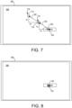
FIGS. 7 and 8 are schematic illustrations of a user interface displayed on a display device that may be used to calibrate the estimated gaze location of a viewer according to another example of the present disclosure. -
FIG. 9 is a schematic illustration of a user interface displayed on a display device that may be used to calibrate the estimated gaze location of a viewer according to another example of the present disclosure. -
FIG. 10 is a schematic illustration an example head-mounted display device. -
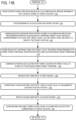
FIGS. 11A ,11B ,11C , and11D are a flow chart of a method for calibrating an estimated gaze location of a viewer of a display device according to an example of the present disclosure. -
FIG. 12 is a simplified schematic illustration of an example of a computing device. -
FIG. 1 shows a schematic view of example implementations of a computing device that may be utilized to calibrate an estimated gaze location of a viewer of a display device. As described in more detail below, in one example a gaze location calibration program uses gaze tracking data from a gaze tracking system to monitor an estimated gaze location of a viewer. The gaze location calibration program may receive image data for display via the display device and, without using input from the viewer, may identify within the image data at least one target visual that may attract a gaze of the viewer and a target location of the target visual. - The gaze location calibration program may then compare the estimated gaze location of the viewer with the target location of the target visual. Using the estimated gaze location and the target location, the program calculates an offset vector. The gaze tracking system is then calibrated using the offset vector to generate an updated estimated gaze location of the viewer.
- In various examples, the computing device may be either physically separated from or integrated into a display device with which a viewer may interact.
Fig. 1 schematically shows an example of acomputing device 10 that is physically separated from adisplay device 14. In this example, thecomputing device 10 may comprise or be integrated into a separate device, such as a set-top box, gaming console, web camera, head-mounted computing device or other wearable computing device, keyboard, dedicated peripheral, or other like device that does not include an integrated display. - The
computing device 10 may be operatively connected with thedisplay device 14 using a wired connection, or may employ a wireless connection via WiFi, Bluetooth, or any other suitable wireless communication protocol. For example, thecomputing device 10 may be communicatively coupled to anetwork 16. Thenetwork 16 may take the form of a local area network (LAN), wide area network (WAN), wired network, wireless network, personal area network, or a combination thereof, and may include the Internet. Additional details regarding the components and computing aspects of thecomputing device 10 are described in more detail below with reference toFIG. 12 . -
FIG. 1 also shows an example of acomputing device 12 integrated into a head-mounted display (HMD)device 18. TheHMD device 18 may create and display to a first viewer 22 a virtual reality environment or a mixed reality environment. In these examples, theHMD device 18 may include adisplay program 26 that may generate the virtual environment or mixed reality environment for display via the HMD device. The virtual environment may include one or more visual elements in the form of virtual images, such as three-dimensional (3D) holographic objects and two-dimensional (2D) virtual images, that are generated and displayed viaHMD device 18. In a mixed reality environment, theHMD device 18 may enable the viewer to view such holographic objects and virtual images within the physical environment surrounding the viewer. - As described in more detail below, in some examples the
HMD device 18 may comprise a transparent, semi-transparent or non-transparent display that is supported in front of a viewer's eye or eyes. TheHMD device 18 may include various sensors and related systems that receive physical environment data from a physical environment. For example, theHMD device 18 may include adepth sensor system 30 that includes one or more depth cameras that generate depth image data. - In some examples the
HMD device 18 may include anoptical sensor system 32 that utilizes at least one outward facing sensor, such as an RGB camera or other optical sensor. The outward facing sensor may capture two-dimensional image information from the physical environment. TheHMD device 18 may also include aposition sensor system 34 comprising one or more accelerometers, gyroscopes, head tracking systems, and/or other sensors for determining a position or orientation of a user. - The
HMD device 18 may also include atransducer system 38 comprising one or more actuators that convert an electrical signal into another form of energy. In some examples, thetransducer system 38 may include one or more speakers for providing audio feedback to a viewer. In other examples thetransducer system 38 may include one or more tactile transducers for generating and providing haptic feedback to the viewer, such as vibrations. TheHMD device 18 may also include amicrophone system 42 and one or more microphones for receiving audio input from the physical environment. - Additionally, the example illustrated in
FIG. 1 shows thecomputing device 12 integrated into theHMD device 18. It will be appreciated that in other examples thecomputing device 12 may be a separate component from theHMD device 18. Many types and configurations ofHMD devices 18 having various form factors may be used and are within the scope of the present disclosure. A more detailed description of an example HMD device is provided below with reference toFIG. 10 . - It also will be appreciated that the
computing device 12 may comprise or be integrated into any other suitable type or form of display device or other computing device, such as a tablet, notebook, smartphone, or other mobile computing device, desktop computing device, standalone monitor, wall-mounted display, interactive whiteboard, or other like device having an integrated display. Such devices may also include a gaze tracking system, as described in more detail below. - Both
computing device 10 andcomputing device 12 may include a gazelocation calibration program 46 that may be stored inmass storage 40. The gazelocation calibration program 46 may be loaded intomemory 48 and executed by aprocessor 52 to perform one or more of the methods and processes described in more detail below. -
Computing device 10 andcomputing device 12 may receivegaze tracking data 50 from agaze tracking system 54. In various examples thegaze tracking system 54 may be located indisplay device 14,HMD device 18, or in a common enclosure with any other suitable type or form of display device, including but not limited to those example devices having an integrated display discussed above. In other examples, thegaze tracking system 54 andcomputing device 10 may be integrated into a common enclosure that does not include an integrated display, such as a head-mounted or other wearable device, or in any other suitable type or form of computing device that does not include an integrated display, including but not limited to those example devices without an integrated display discussed above. More detailed descriptions of examplegaze tracking systems 54 are discussed below with referenceexample HMD device 1000 illustrated inFIG. 10 . - With continued reference to
Fig. 1 , theexample display device 14 may include adisplay system 58 for presenting one or more visual elements to asecond viewer 62. As described in more detail below, the gazelocation calibration program 46 may utilizegaze tracking data 50 from thegaze tracking system 54 to determine an estimated gaze location of a viewer and to calculate an offset vector based on the estimated gaze location and the location of a target visual displayed bydisplay device 14,HMD 18 or other display device. The offset vector may be used to calibrate the gaze tracking system and to update an estimated gaze location of the viewer. - With reference now to
FIGS. 2-9 , descriptions of example use cases will now be provided.FIG. 2 is a schematic illustration of several viewers in aroom 200 interacting with computing and display devices that use gaze tracking data from gaze tracking systems. In one example,viewer James 202 is watching avideo 206 that is displayed on a wall-mounteddisplay 210. In various examples thevideo 206 may be an interactive video, a portion of a game, or other content that may provide an interactive experience via gaze tracking. In this example, wall-mounteddisplay 210 is communicatively coupled to a set-top box 212 that comprises agaze tracking system 54 and a computing device that includes gazelocation calibration program 46. Usinggaze tracking data 50 from thegaze tracking system 54, the gazelocation calibration program 46 may monitor the estimated gaze location ofviewer James 202 on the screen of the wall-mounteddisplay 210. - With reference also to
FIG. 1 , the gazelocation calibration program 46 receivesimage data 64 comprising thevideo 206 via a calibration application programming interface (API) 66. With reference now toFIG. 3 , in this example theimage data 64 includes a target visual in the form of a computer-generated soaringbird 214. As thevideo 206 plays, thebird 214 soars through the sky along apredetermined path 220 comprising a plurality of target locations during a target timeframe. In various examples the target timeframe comprises 2 seconds, 4 seconds, 6 seconds, or any other suitable timeframe. The flight and movement of thebird 214 is rendered to appear realistic and natural to a viewer, such that the viewer is naturally inclined to follow the flight of the bird. - Advantageously in some examples, and without using input from
viewer James 202, the gazelocation calibration program 46 may analyze theimage data 64 to programmatically determine that the soaringbird 214 may attract a gaze ofviewer James 202. For example, the gazelocation calibration program 46 may determine that the visual impact of the soaring bird is significantly more interesting to a viewer than the stationary cloud, palm tree and other elements of thevideo 206. Accordingly, the gazelocation calibration program 46 may determine thatviewer James 202 will direct his gaze to thebird 214 as it travels along thepredetermined path 220. - In some examples, the
image data 64 may comprise target visual metadata that affirmatively designates thebird 214 as a target visual that is likely to attract the attention of a viewer. The gazelocation calibration program 46 may be configured to use such target visual metadata to identify the bird and its target location in thevideo 206. For example, the developer ofvideo 206 may include target visual metadata that identifies thebird 214 as likely to attract the attention of a viewer and correspondingly to be followed by the viewer's gaze. Advantageously, the gazelocation calibration program 46 may utilize such developer-provided metadata in calibrating the gaze tracking system as discussed below. - The gaze
location calibration program 46 may further identifytarget locations 224 of thebird 214 as it traverses thepredetermined path 220. Examples ofsuch target locations 224 are illustrated in the example ofFIG. 3 by "+" signs. Using gaze tracking data from thegaze tracking system 54, the gazelocation calibration program 46 may monitor the estimatedgaze location 230 ofviewer James 202 during the target timeframe, and at instances that are temporally correlated with thetarget locations 224. Examples of such estimatedgaze locations 230 are illustrated in the example ofFIG. 3 by "-" signs. - The gaze
location calibration program 46 compares the estimatedgaze locations 230 with thetarget locations 224 at a plurality of such corresponding instances during the target timeframe. For each comparison an offsetvector 234 is calculated based on the estimatedgaze location 230 and thecorresponding target location 224 at that instance. Using the offsetvectors 234, the gazelocation calibration program 46 then calibrates thegaze tracking system 54 to generate an updated gaze location ofviewer James 202. For example, the updated gaze location may substantially correspond to targetlocations 224 along thepredetermined path 220. Additionally, becauseviewer James 202 perceives thebird 214 as a naturally-occurring feature ofvideo 206, the gazelocation calibration program 46 advantageously may calibrate thegaze tracking system 54 without interrupting or distracting James from his immersive experience in watching the video. - In an example not forming part of the literal wording of the claims granted, the gaze
location calibration program 46 may estimate aprobability 70 thatviewer James 202 is gazing at atarget location 224 of thebird 214. For example, thelocation calibration program 46 may analyze various visual elements of thevideo 206 and estimate that, while thebird 214 is soaring through the sky past the palm tree and cloud, it is 85% probable thatviewer James 202 is following and gazing at the bird. For example, the gazelocation calibration program 46 may determine the probability based on the visual impact of the soaring bird being significantly more interesting to a viewer than the stationary cloud, palm tree and other elements of thevideo 206. It will be appreciated that any suitable method for determining such a probability may be utilized and is within the scope of the present disclosure. -
Such probability 70 may then be used to calculate the offset vectors and determine an updated estimated gaze location. For example, where one offset vector exceeds a predetermined threshold offset value, this could indicate thatviewer James 202 has looked away from thebird 214 at that particular instance. Combining the 85% probability with the offset vector exceeding the predetermined threshold offset, the gazelocation calibration program 46 may exclude this offset vector sample from the other offset vector samples in calibrating thegaze tracking system 54. - In an embodiment of the invention, the gaze
location calibration program 46 may receive via thecalibration API 66 metadata comprising a probability thatviewer James 202 is following and gazing at thebird 214 in thevideo 206. As in the previous example, combining the probability with the offset vector exceeding a predetermined threshold offset, the gazelocation calibration program 46 may exclude this offset vector sample from the other offset vector samples in calibrating thegaze tracking system 54. It will also be appreciated that such a probability may be utilized in any other suitable manner to calculate an offset vector and/or calibrate the gaze tracking system. - As another example, such a probability could be used to appropriately scale the importance of the offset vector calculated with respect to the
bird 214. If the probability is high thatJames 202 is looking at thebird 214, and the probability is low that he is looking at the palm tree, then the offset vector with respect to thebird 214 is weighted as being more important than an offset vector with respect to the palm tree. - In other examples, the gaze
location calibration program 46 may identify a plurality of target locations that each correspond to one of a plurality of target visuals within image data that may attract the gaze of the viewer. For example and with reference now toFIGS. 2 and4 ,viewer Julius 240 may be immersed in a mixed reality experience provided by an application that uses image data to generate holograms displayed via anHMD device 18 in the form ofglasses 244. In this example, the holograms may comprise threecoffee cups dots 414 that are displayed during a loading procedure of the application. - The gaze
location calibration program 46 may determine that an estimatedgaze location 420 ofviewer Julius 240 is nearest to atarget location 424 that corresponds to themiddle coffee cup 406. Accordingly, the gazelocation calibration program 46 may determine thatviewer Julius 240 is actually gazing at themiddle coffee cup 406. The gazelocation calibration program 46 may then calculate an offsetvector 430 based on the estimatedgaze location 420 and thetarget location 424 of themiddle coffee cup 406. Thetarget location 424 may correspond to the centroid of thecoffee cup 406, a point on the periphery of the coffee cup, or any other suitable location on the image of the coffee cup. - In other examples, the gaze
location calibration program 46 may be configured to utilize input from a viewer to calibrate a gaze tracking system. For example and with reference now toFIGS. 2 ,5 and 6 ,viewer Rebecca 248 may play acomputer game 74 on hertablet computer 252. Thetablet computer 252 may include a display comprising touch-sensitive screen 256, agaze tracking system 54 and a gazelocation calibration program 46. - With reference now to
FIGS. 5 and 6 , in one example the gazelocation calibration program 46 may be configured to control thetablet computer 252 to display aselectable button 502 on touch-sensitive screen 256.Viewer Rebecca 248 may naturally gaze at thebutton 502 when it appears. This actual gaze location ofviewer Rebecca 248 is illustrated by actualgaze location indicator 504 inFIG. 5 . - The
gaze tracking system 54 of thetablet computer 252 may track and estimate anuncalibrated location 508 of viewer Rebecca's gaze location. In some examples, such estimated,uncalibrated gaze location 508 may be offset from her actual gaze location. For example and as shown inFIG. 5 , while heractual gaze location 504 may correspond to thebutton 502, the estimated,uncalibrated gaze location 508 may be spaced from the button. - To initiate a calibration operation,
viewer Rebecca 248 may provide a predetermined user input via thetablet computer 252. In response, the gazelocation calibration program 46 may control thetablet computer 252 to display a guide visual 512 at theuncalibrated location 508. In the example ofFIG. 5 , the guide visual 512 is illustrated as a circle and thebutton 502 is illustrated as a rectangular region. It will be appreciated that any other suitable shapes may be utilized for the guide visual 512 andbutton 502. - In one example, the predetermined user input may comprise
viewer Rebecca 248 pressing and holding a physical button on thetablet computer 252 for at least a predetermined triggering timeframe, such as 200 milliseconds (ms), 300 ms, 400 ms, or any other suitable timeframe. It will be appreciated that the predetermined user input may also comprise any other suitable user input including, but not limited to, touching the touch-sensitive screen 256 at a location corresponding to thebutton 502 or another designated location, performing a gesture that is captured by adepth sensor system 30, gazing atbutton 502 for at least a predetermined dwell time, etc. - When
viewer Rebecca 248 sees the guide visual 512 appear at theuncalibrated location 508, her attention and gaze are naturally attracted to the visual.Viewer Rebecca 248 may then provide recalibrating user input that moves the guide visual 512 from its initial,uncalibrated gaze location 508 to a calibratedlocation 514 corresponding to the location of thebutton 502 as shown inFIG. 6 . In the present example, upon receiving the recalibrating user input thegaze tracking system 54 may be disabled, and the recalibrating user input may be received from a sensor different from the sensor that provided the predetermined input. For example,viewer Rebecca 248 may provide the recalibrating user input via a head-tracking sensor and/or other position sensor, depth camera, trackpad, mouse or any other suitable sensor or input device. In other examples, upon receiving the recalibrating user input thegaze tracking system 54 may not be disabled, and the recalibrating user input may be received from the same sensor that provided the predetermined input. - With reference to
FIG. 6 , in oneexample viewer Rebecca 248 may use head movements to provide recalibrating user input via a head-tracking sensor to drive the guide visual 512 from the initial,uncalibrated gaze location 508 to the calibratedlocation 514. In response, the gazelocation calibration program 46 may control thetablet computer 252 to display the guide visual 512 at the calibratedlocation 514 that corresponds to the location of thebutton 502. The gazelocation calibration program 46 may then calculate an offsetvector 520 based on theuncalibrated location 508 and the calibratedlocation 514. - It will be appreciated that the offset vector may comprise a horizontal dx component and a vertical dy component that represent an error in the estimated gaze location. The gaze
location calibration program 46 may utilize these components in a local transformation of gaze computation logic utilized by thegaze tracking system 54 to calibrate the system to produce more accurate estimated gaze locations. - With reference now to
FIGS. 7 and 8 , in another example the gazelocation calibration program 46 may be configured to utilize a live gaze feedback loop to calibrate thegaze tracking system 54. In this example, thegaze tracking system 54 may be configured to control thetablet computer 252 to displayselectable button 702 on touch-sensitive screen 256.Viewer Rebecca 248 may naturally gaze at thebutton 702 when it appears, as indicated by initial actualgaze location indicator 704 inFIG. 7 . - The
gaze tracking system 54 may estimate an initial estimated (uncalibrated)gaze location 710 ofviewer Rebecca 248, and may display a guide visual 714 at the initial estimated gaze location. Whenviewer Rebecca 248 sees the guide visual 714 appear at the initial estimatedgaze location 710, her attention and gaze are naturally attracted to the visual. Whenviewer Rebecca 248 moves her gaze to the guide visual 714 at initial estimatedgaze location 710, the gazelocation calibration program 46 may then determine an updated estimatedgaze location 718 of viewer Rebecca. - The gaze
location calibration program 46 may then display the guide visual 714 at the updated estimatedgaze location 718. Whenviewer Rebecca 248 sees the guide visual 714 appear at the updated estimatedgaze location 718, again her gaze is naturally attracted to the visual. Whenviewer Rebecca 248 moves her gaze to the updated estimatedgaze location 718, a subsequent updated estimated gaze location may be determined. It will be appreciated that any number of iterations of the above-described process may be utilized to capture additional data points. It will also be appreciated that the above-described process creates a feedback loop in which an estimated gaze location and corresponding guide visual will move in the same direction as the movement of the actual gaze location of the viewer. - As shown in the example of
FIG. 7 , the initial estimatedgaze location 710 is spaced from the initial actualgaze location indicator 704 by an offsetvector 720. Similarly, the updated estimatedgaze location 718 is spaced from the initial estimatedgaze location 710 by an offset vector 720', which may have substantially the same magnitude as offsetvector 720. Utilizing offsetvector 720 and offset vector 720', the gazelocation calibration program 46 may calibrate thegaze tracking system 54 to generate updated estimated gaze locations of viewer Rebecca in subsequent iterations. In some examples, the gazelocation calibration program 46 may utilize the calculated offset vectors to generate and apply a local transformation to gaze computation logic utilized by thegaze tracking system 54 to calibrate the system to produce more accurate estimated gaze locations. For example and with reference toFIG. 8 , after calibration thegaze tracking system 54 may generate an estimatedgaze location 730 that more closely corresponds to anactual gaze location 734 of the viewer. - With reference now to
FIG. 9 , in another example the gazelocation calibration program 46 may be configured to utilizegaze tracking data 50 over a predetermined timeframe to calibrate thegaze tracking system 54. In one example, the gazelocation calibration program 46 may be configured to establish aselection region 904 that encompasses a target visual, such asselectable button 908 located at atarget location 910. It will be appreciated that theselection region 904 may comprise any suitable shape that is larger than the target visual. -
Viewer Rebecca 248 may fix her gaze at thebutton 908, as indicated atactual gaze location 912. The gazelocation calibration program 46 may determine an estimatedgaze location 916 ofviewer Rebecca 248 that at least partially overlaps theselection region 904. The gazelocation calibration program 46 may determine that the estimatedgaze location 916 dwells within at least a portion of theselection region 904 for at least a dwell timeframe. In some examples the period of the dwell timeframe may be 1 second (sec), 2 secs, 3 secs, or any other suitable timeframe. - Based on determining that the estimated
gaze location 916 dwells within at least a portion of theselection region 904 for at least the dwell timeframe, the gazelocation calibration program 46 may determine thatviewer Rebecca 248 is gazing at thebutton 908 attarget location 910 during the dwell timeframe. Accordingly, the gazelocation calibration program 46 may then calculate an offsetvector 920 between the estimatedgaze location 916 and thetarget location 910 of thebutton 908, and may use the offset vector to calibrate thegaze tracking system 54 as described above. It will be appreciated that thetarget location 910 ofbutton 908 may be the centroid of the button, a point on a periphery of the button, or any other suitable location on the button. - With reference now to
FIG. 10 , one example of anHMD device 1000 in the form of a pair of wearable glasses with a transparent display is provided. It will be appreciated that in other examples, theHMD device 1000 may take other suitable forms in which a transparent, semi-transparent, and/or non-transparent display is supported in front of a viewer's eye or eyes. It will also be appreciated that the HMD devices shown inFIGS. 1 and2 may take the form of theHMD device 1000, as described in more detail below, or any other suitable HMD device. - The
HMD device 1000 includes adisplay system 1002 and a see-through ortransparent display 1004 that enables images such as holographic objects to be delivered to the eyes of a wearer of the HMD device. Thetransparent display 1004 may be configured to visually augment an appearance of a real-world, physical environment to a wearer viewing the physical environment through the transparent display. For example, the appearance of the physical environment may be augmented by graphical content (e.g., one or more pixels each having a respective color and brightness) that is presented via thetransparent display 1004 to create an augmented reality environment. - The
transparent display 1004 may also be configured to enable a wearer of the HMD device to view a physical, real-world object in the physical environment through one or more partially transparent pixels that are displaying a virtual object representation. As shown inFIG. 10 , in one example thetransparent display 1004 may include image-producing elements located within lenses 1006 (such as, for example, a see-through Organic Light-Emitting Diode (OLED) display). As another example, thetransparent display 1004 may include a light modulator on an edge of thelenses 1006. In this example, thelenses 1006 may serve as a light guide for delivering light from the light modulator to the eyes of a wearer. Such a light guide may enable a wearer to perceive a 3D holographic image located within the physical environment that the wearer is viewing, while also allowing the wearer to view physical objects in the physical environment, thus creating an augmented reality environment. - The
HMD device 1000 may also include various sensors and related systems. For example, theHMD device 1000 may include agaze tracking system 1008 that includes one or more image sensors configured to acquire image data in the form of gaze tracking data from a wearer's eyes. Provided the wearer has consented to the acquisition and use of this information, thegaze tracking system 1008 may use this information to track a position and/or movement of the wearer's eyes. - In one example, the
gaze tracking system 1008 includes a gaze detection subsystem configured to detect a direction of gaze of each eye of a wearer. The gaze detection subsystem may be configured to determine gaze directions of each of a wearer's eyes in any suitable manner. For example, the gaze detection subsystem may comprise one or more light sources, such as infrared light sources, configured to cause a glint of light to reflect from the cornea of each eye of a wearer. One or more image sensors may then be configured to capture an image of the wearer's eyes. - Images of the glints and of the pupils as determined from image data gathered from the image sensors may be used to determine an optical axis of each eye. Using this information, the
gaze tracking system 1008 may then determine a direction the wearer is gazing. Thegaze tracking system 1008 may additionally or alternatively determine at what physical or virtual object the wearer is gazing, and at what location on such physical or virtual object the wearer is gazing. Such gaze tracking data may then be provided to theHMD device 1000. - It will also be understood that the
gaze tracking system 1008 may have any suitable number and arrangement of light sources and image sensors. For example and with reference toFIG. 10 , thegaze tracking system 1008 of theHMD device 1000 may utilize at least oneinward facing sensor 1010. - The
HMD device 1000 may also include sensor systems that receive physical environment data from the physical environment. For example, theHMD device 1000 may also include ahead tracking system 1012 that utilizes one or more pose sensors, such aspose sensors 1014 onHMD device 1000, to capture head pose data and thereby enable position tracking, direction/location and orientation sensing, and/or motion detection of the wearer's head. - In one example,
head tracking system 1012 may comprise an inertial measurement unit (IMU) configured as a three-axis or three-degree of freedom position sensor system. This example position sensor system may, for example, include three gyroscopes to indicate or measure a change in orientation of theHMD device 1000 within 3D space about three orthogonal axes (e.g., x, y, and z, or roll, pitch, and yaw). In some examples, the orientation derived from the sensor signals of the IMU may be used to display, via thetransparent display 1004, one or more virtual objects with a body-locked position in which the position of each virtual object appears to be fixed relative to the wearer of the see-through display and the position of each virtual object appears to be moveable relative to real-world objects in the physical environment. - In another example,
head tracking system 1012 may comprise an IMU configured as a six-axis or six-degree of freedom position sensor system. This example position sensor system may, for example, include three accelerometers and three gyroscopes to indicate or measure a change in location of theHMD device 1000 along the three orthogonal axes and a change in device orientation about the three orthogonal axes. - The
head tracking system 1012 may also support other suitable positioning techniques, such as GPS or other global navigation systems. Further, while specific examples of position sensor systems have been described, it will be appreciated that any other suitable position sensor systems may be used. For example, head pose and/or movement data may be determined based on sensor information from any combination of sensors mounted on the wearer and/or external to the wearer including, but not limited to, any number of gyroscopes, accelerometers, inertial measurement units, GPS devices, barometers, magnetometers, cameras (e.g., visible light cameras, infrared light cameras, time-of-flight depth cameras, structured light depth cameras, etc.), communication devices (e.g., WIFI antennas/interfaces), etc. - In some examples, the
HMD device 1000 may also include an optical sensor system that utilizes one or more outward facing sensors, such asoptical sensor 1016 onHMD device 1000, to capture image data. The outward facing sensor(s) may detect movements within its field of view, such as gesture-based inputs or other movements performed by a wearer or by a person or physical object within the field of view. The outward facing sensor(s) may also capture 2D image information and depth information from the physical environment and physical objects within the environment. For example, the outward facing sensor(s) may include a depth camera, a visible light camera, an infrared light camera, and/or a position tracking camera. - The optical sensor system may include a depth tracking system that generates depth tracking data via one or more depth cameras. In one example, each depth camera may include left and right cameras of a stereoscopic vision system. Time-resolved images from one or more of these depth cameras may be registered to each other and/or to images from another optical sensor such as a visible spectrum camera, and may be combined to yield depth-resolved video.
- In other examples, a structured light depth camera may be configured to project a structured infrared illumination, and to image the illumination reflected from a scene onto which the illumination is projected. A depth map of the scene may be constructed based on spacings between adjacent features in the various regions of an imaged scene. In still other examples, a depth camera may take the form of a time-of-flight depth camera configured to project a pulsed infrared illumination onto a scene and detect the illumination reflected from the scene. For example, illumination may be provided by an
infrared light source 1018. It will be appreciated that any other suitable depth camera may be used within the scope of the present disclosure. - The outward facing sensor(s) may capture images of the physical environment in which a wearer of the HMD device is situated. With respect to the
HMD device 1000, in one example an augmented reality display program may include a 3D modeling system that uses such captured images to generate a virtual environment that models the physical environment surrounding the wearer of the HMD device. In some examples, theoptical sensor 1016 may cooperate with the IMU to determine the location and the orientation of theHMD device 1000 in six degrees of freedom. Such location and orientation information may be used to display, via thetransparent display 1004, one or more virtual objects with a world-locked position in which a position of each virtual object appears to be fixed relative to real-world objects viewable through the transparent display, and the position of each virtual object appears to be moveable relative to a wearer of the see-through display. - The
HMD device 1000 may also include a microphone system that includes one or more microphones, such asmicrophone 1020, that capture audio data. In other examples, audio may be presented to the wearer via one or more speakers, such asspeaker 1022 on theHMD device 1000. - The
HMD device 1000 may also include a controller, such ascontroller 1024. Thecontroller 1024 may include a logic subsystem and a storage subsystem, as discussed in more detail below with respect toFIG. 12 , that are in communication with the various sensors and systems of theHMD device 1000. In one example, the storage subsystem may include instructions that are executable by the logic subsystem to receive signal inputs from the sensors, determine a pose of theHMD device 1000, and adjust display properties for content displayed via thetransparent display 1004. -
FIGS. 11A and11B illustrate a flow chart of amethod 1100 for calibrating an estimated gaze location of a viewer of a display device according to an implementation of the present disclosure. The following description ofmethod 1100 is provided with reference to the software and hardware components described above and shown inFIGS. 1-10 . It will be appreciated thatmethod 1100 may also be performed in other contexts using other suitable hardware and software components. - With reference to
FIG. 11A , at 1102 themethod 1100 includes monitoring the estimated gaze location of the viewer using gaze tracking data from a gaze tracking system. At 1104 themethod 1100 includes receiving image data for display via the display device. At 1106 themethod 1100 includes, without using input from the viewer, identifying within the image data at least one target visual that attracts a gaze of the viewer and a target location of the at least one target visual. - At 1108 the
method 1100 includes comparing the estimated gaze location of the viewer with the target location of the at least one target visual. At 1110 themethod 1100 includes calculating an offset vector based on the estimated gaze location and the target location. At 1114 themethod 1100 includes calibrating the gaze tracking system using the offset vector to generate an updated estimated gaze location of the viewer. At 1116 themethod 1100 includes estimating a probability that the viewer is gazing at the target location. At 1120 themethod 1100 includes utilizing the probability in calculating the offset vector. - With reference now to
FIG. 11B , at 1122 themethod 1100 includes, from a content source that is providing the image data via a calibration API, receiving a probability that the viewer is gazing at the target location. At 1124 themethod 1100 includes utilizing the probability in calculating the offset vector. At 1126 themethod 1100 includes, where the image data is received from a content source via a calibration API, and the image data comprises target visual metadata corresponding to the at least one target visual, using the target visual metadata to identify the target location. - At 1128 the
method 1100 may include, where the image data comprises a video and the at least one target visual traverses a predetermined path during a target timeframe, monitoring the estimated gaze location during the target timeframe. At 1130 themethod 1100 may include comparing the estimated gaze location with the target location of the at least one target visual at a plurality of instances during the target timeframe. - At 1132 the
method 1100 includes receiving a first user input via a first sensor. At 1134 themethod 1100 includes, in response to receiving the first user input, displaying a guide visual at an uncalibrated location via the display device. At 1136 themethod 1100 may include receiving a second user input via a second sensor. At 1140 themethod 1100 may include, using the second user input, displaying the guide visual at a calibrated location that corresponds to the target location. With reference now toFIG. 11C , at 1144 themethod 1100 may include calculating the offset vector based on the uncalibrated location and the calibrated location. - At 1148 the
method 1100 the second sensor may be selected from the group consisting of a head-tracking sensor, a depth camera, a mouse, and a trackpad. At 1150 themethod 1100 may include establishing a selection region that encompasses the target visual. At 1154 themethod 1100 may include determining that the estimated gaze location of the viewer dwells within at least a portion of the selection region for at least a dwell timeframe. At 1158 themethod 1100 may include, based on determining that the estimated gaze location dwells within at least a portion of the selection region for at least the dwell timeframe, determining that the viewer is gazing at the target location of the target visual during the dwell timeframe. - At 1162 the
method 1100 includes, where the estimated gaze location of the viewer is an initial estimated gaze location, displaying a guide visual at the initial estimated gaze location via the display device. At 1166 themethod 1100 includes determining an updated estimated gaze location of the viewer. At 1170 themethod 1100 includes displaying the guide visual at the updated estimated gaze location, where the updated estimated gaze location is spaced from the estimated gaze location by the offset vector. With reference now toFIG. 11D , at 1174 themethod 1100 includes calculating the offset vector based on the updated estimated gaze location and the estimated gaze location. - At 1178 the
method 1100 includes identifying a plurality of target locations that each correspond to one of a plurality of target visuals within the image data that attracts the gaze of the viewer. At 1182 themethod 1100 includes determining that the estimated gaze location is nearest to one of the plurality of target locations that corresponds to one of the plurality of target visuals. At 1186 themethod 1100 includes calculating the offset vector based on the estimated gaze location and the one of the plurality of target location. - It will be appreciated that
method 1100 is provided by way of example and is not meant to be limiting. Therefore, it is to be understood thatmethod 1100 may include additional and/or alternative steps than those illustrated inFIGS. 11A ,11B ,11C and11D . Further, it is to be understood thatmethod 1100 may be performed in any suitable order. Further still, it is to be understood that one or more steps may be omitted frommethod 1100 without departing from the scope of this disclosure. -
FIG. 12 schematically shows a nonlimiting example of acomputing system 1200 that may perform one or more of the above described methods and processes.Computing device 10 andcomputing device 12 may take the form of or include one or more aspects ofcomputing system 1200.Computing system 1200 is shown in simplified form. It is to be understood that virtually any computer architecture may be used without departing from the scope of this disclosure. In different examples,computing system 1200 may take the form of a mainframe computer, server computer, desktop computer, tablet computer, home entertainment computer, network computing device, tablet, notebook, smartphone, or other mobile computing device, mobile communication device, gaming device, etc. - As shown in
FIG. 12 ,computing system 1200 includes alogic subsystem 1204 and astorage subsystem 1208.Computing system 1200 may optionally include asensor subsystem 1212,display subsystem 1216,communication subsystem 1220,input subsystem 1222 and/or other subsystems and components not shown inFIG. 12 .Computing system 1200 may also include computer readable media, with the computer readable media including computer readable storage media and computer readable communication media.Computing system 1200 may also optionally include other user input devices such as keyboards, mice, game controllers, and/or touch screens, for example. Further, in some embodiments the methods and processes described herein may be implemented as a computer application, computer service, computer API, computer library, and/or other computer program product in a computing system that includes one or more computers. -
Logic subsystem 1204 may include one or more physical devices configured to execute one or more instructions. For example, thelogic subsystem 1204 may be configured to execute one or more instructions that are part of one or more applications, services, programs, routines, libraries, objects, components, data structures, or other logical constructs. Such instructions may be implemented to perform a task, implement a data type, transform the state of one or more devices, or otherwise arrive at a desired result. - The
logic subsystem 1204 may include one or more processors that are configured to execute software instructions. Additionally or alternatively, the logic subsystem may include one or more hardware or firmware logic machines configured to execute hardware or firmware instructions. Processors of the logic subsystem may be single core or multicore, and the programs executed thereon may be configured for parallel or distributed processing. The logic subsystem may optionally include individual components that are distributed throughout two or more devices, which may be remotely located and/or configured for coordinated processing. One or more aspects of the logic subsystem may be virtualized and executed by remotely accessible networked computing devices configured in a cloud computing configuration. -
Storage subsystem 1208 may include one or more physical, persistent devices configured to hold data and/or instructions executable by thelogic subsystem 1204 to implement the herein described methods and processes. When such methods and processes are implemented, the state ofstorage subsystem 1208 may be transformed (e.g., to hold different data). -
Storage subsystem 1208 may include removable media and/or built-in devices.Storage subsystem 1208 may include optical memory devices (e.g., CD, DVD, HD-DVD, Blu-Ray Disc, etc.), semiconductor memory devices (e.g., RAM, EPROM, EEPROM, etc.) and/or magnetic memory devices (e.g., hard disk drive, floppy disk drive, tape drive, MRAM, etc.), among others.Storage subsystem 1208 may include devices with one or more of the following characteristics: volatile, nonvolatile, dynamic, static, read/write, read-only, random access, sequential access, location addressable, file addressable, and content addressable. - In some examples, aspects of
logic subsystem 1204 andstorage subsystem 1208 may be integrated into one or more common devices through which the functionally described herein may be enacted, at least in part. Such hardware-logic components may include field-programmable gate arrays (FPGAs), program- and application-specific integrated circuits (PASIC / ASICs), program- and application-specific standard products (PSSP / ASSPs), system-on-a-chip (SOC) systems, and complex programmable logic devices (CPLDs), for example. -
FIG. 12 also shows an aspect of thestorage subsystem 1208 in the form of removable computerreadable storage media 1224, which may be used to store data and/or instructions executable to implement the methods and processes described herein. Removable computer-readable storage media 1224 may take the form of CDs, DVDs, HD-DVDs, Blu-Ray Discs, EEPROMs, and/or floppy disks, among others. - It is to be appreciated that
storage subsystem 1208 includes one or more physical, persistent devices. In contrast, in some implementations aspects of the instructions described herein may be propagated in a transitory fashion by a pure signal (e.g., an electromagnetic signal, an optical signal, etc.) that is not held by a physical device for at least a finite duration. Furthermore, data and/or other forms of information pertaining to the present disclosure may be propagated by a pure signal via computer-readable communication media. - When included,
sensor subsystem 1212 may include one or more sensors configured to sense different physical phenomenon (e.g., visible light, infrared light, sound, acceleration, orientation, position, etc.) as described above.Sensor subsystem 1212 may be configured to provide sensor data tologic subsystem 1204, for example. Such data may include gaze tracking information, image information, ambient lighting information, depth information, audio information, position information, motion information, user location information, and/or any other suitable sensor data that may be used to perform the methods and processes described above. - When included,
display subsystem 1216 may be used to present a visual representation of data held bystorage subsystem 1208. As the above described methods and processes change the data held by thestorage subsystem 1208, and thus transform the state of the storage subsystem, the state of thedisplay subsystem 1216 may likewise be transformed to visually represent changes in the underlying data. Thedisplay subsystem 1216 may include one or more display devices utilizing virtually any type of technology. Such display devices may be combined withlogic subsystem 1204 and/orstorage subsystem 1208 in a shared enclosure, or such display devices may be peripheral display devices. - When included,
communication subsystem 1220 may be configured to communicatively couplecomputing system 1200 with one or more networks and/or one or more other computing devices.Communication subsystem 1220 may include wired and/or wireless communication devices compatible with one or more different communication protocols. As nonlimiting examples, thecommunication subsystem 1220 may be configured for communication via a wireless telephone network, a wireless local area network, a wired local area network, a wireless wide area network, a wired wide area network, etc. In some embodiments, the communication subsystem may allowcomputing system 1200 to send and/or receive messages to and/or from other devices via a network such as the Internet. - When included,
input subsystem 1222 may comprise or interface with one or more sensors or user-input devices such as a game controller, gesture input detection device, voice recognizer, inertial measurement unit, keyboard, mouse, or touch screen. In some embodiments, theinput subsystem 1222 may comprise or interface with selected natural user input (NUI) componentry. Such componentry may be integrated or peripheral, and the transduction and/or processing of input actions may be handled on- or off-board. Example NUI componentry may include a microphone for speech and/or voice recognition; an infrared, color, stereoscopic, and/or depth camera for machine vision and/or gesture recognition; a head tracker, eye tracker, accelerometer, and/or gyroscope for motion detection and/or intent recognition; as well as electric-field sensing componentry for assessing brain activity. - The term "program" may be used to describe an aspect of
computing device 10 andcomputing device 12 that is implemented to perform one or more particular functions. In some cases, such a program may be instantiated vialogic subsystem 1204 executing instructions held bystorage subsystem 1208. It is to be understood that different programs may be instantiated from the same application, service, code block, object, library, routine, API, function, etc. Likewise, the same program may be instantiated by different applications, services, code blocks, objects, routines, APIs, functions, etc. The term "program" is meant to encompass individual or groups of executable files, data files, libraries, drivers, scripts, database records, etc. - It is to be understood that the configurations and/or approaches described herein are exemplary in nature, and that these specific embodiments or examples are not to be considered in a limiting sense, because numerous variations are possible. The specific routines or methods described herein may represent one or more of any number of processing strategies. As such, various acts illustrated may be performed in the sequence illustrated, in other sequences, in parallel, or in some cases omitted. Likewise, the order of the above-described processes may be changed.
Claims (7)
- A method (1100) for calibrating an estimated gaze location of a viewer of a display device, the method comprising:monitoring (1102) the estimated gaze location (230) of the viewer (202) using gaze tracking data from a gaze tracking system (54) during a target timeframe and at a plurality of instances;receiving (1104), from a content source via a calibration application programming interface, image data including at least one target visual (214) for display via the display device, wherein the image data comprises a video (206), the at least one target visual (214) traverses a predetermined path (220) comprising target locations (224) during the target timeframe and attracts a gaze of the viewer (202), and the image data comprises target visual metadata that identifies the at least one target visual (214) in the video (206), and receiving (1122), from the content source via the calibration application programming interface, a probability (70) that the viewer (202) is gazing at the target locations (224);without using input from the viewer (202), identifying (1106) within the image data the at least one target visual (214);without using input from the viewer (202), using (1126) the target visual metadata to identify the target locations (224) of the at least one target visual (214);comparing (1108) the estimated gaze locations (230) of the viewer (202) with the target locations (224) of the at least one target visual (214) at the plurality of instances during the target timeframe;calculating (1110) an offset vector (234) for each comparison (1108) based on the estimated gaze location (230) and the target location (224); andcalibrating (1114) the gaze tracking system (54) using the offset vectors (234) to generate updated estimated gaze locations of the viewer (202),wherein an offset vector (234) is excluded (1124) from the other offset vectors (234) in calibrating (1114) the gaze tracking system (54) based on combining the probability (70) with the offset vector (234) exceeding a predetermined threshold offset value.
- The method of claim 1, wherein the at least one target visual (214) is a first target visual (214), the image data includes a plurality of target visuals (214) that may attract the gaze of the viewer (240), and the probability (70) is used to weight an importance of the offset vectors (234) calculated with respect to the first target visual (214).
- The method of claim 1, further comprising:identifying a plurality of target locations (224) that each correspond to one (406) of a plurality of target visuals (214) within the image data that may attract the gaze of the viewer (240);determining that the estimated gaze location (420) is nearest to one (424) of the plurality of target locations (224) that corresponds to one (406) of the plurality of target visuals (214);calculating the offset vector (430) based on the estimated gaze location (420) and the one (424) of the plurality of target locations (224).
- A computing device for calibrating an estimated gaze location of a viewer of a display device, the computing device comprising:
a gaze location calibration program (46) executed by a processor of the computing device, the gaze location calibration program (46) configured to:monitor (1102) the estimated gaze location (230) of the viewer (202) using gaze tracking data from a gaze tracking system (54) during a target timeframe and at a plurality of instances;receive (1104), from a content source via a calibration application programming interface, image data including at least one target visual (214) for display via the display device, wherein the image data comprises a video (206), the at least one target visual (214) traverses a predetermined path (220) comprising target locations (224) during the target timeframe and attracts a gaze of the viewer (202), and the image data comprises target visual metadata that identifies the at least one target visual (214) in the video (206), and receive (1122), from the content source via the calibration application programming interface, a probability (70) that the viewer (202) is gazing at the target locations (224);without using input from the viewer (202), identify (1106) within the image data the at least one target visual (214);without using input from the viewer (202), use (1126) the target visual metadata to identify the target locations (224) of the at least one target visual (214);compare (1108) the estimated gaze locations (230) of the viewer (202) with the target locations (224) of the at least one target visual (214) at the plurality of instances during the target timeframe;calculate (1110) an offset vector (234) for each comparison (1108) based on the estimated gaze location (230) and the target location (224); andcalibrate (1114) the gaze tracking system (54) using the offset vectors (234) to generate an updated estimated gaze location of the viewer (202),wherein an offset vector (234) is excluded (1124) from the other offset vectors (234) in calibrating (1114) the gaze tracking system (54) based on combining the probability (70) with the offset vector (234) exceeding a predetermined threshold offset value. - The computing device of claim 4, wherein the gaze location calibration program (46) is further configured to:receive (1132) a first user input via a first sensor;in response to receiving (1132) the first user input, control the display device to display (1134) a guide visual at an uncalibrated location;receive (1136) a second user input via a second sensor;using the second user input, control the display device to display (1140) the guide visual at a calibrated location that corresponds to the target location (224); andcalculate (1144) the offset vector (234) based on the uncalibrated location and the calibrated location.
- The computing device of claim 5, wherein the second sensor is selected (1148) from the group consisting of a head-tracking sensor, a depth camera, a mouse, and a trackpad.
- The computing device of claim 4, wherein the gaze location calibration program (46) is further configured to:establish (1150) a selection region (904) that encompasses the target visual (908);determine (1154) that the estimated gaze location (916) of the viewer (248) dwells within at least a portion of the selection region (904) for at least a dwell timeframe;based on determining that the estimated gaze location (916) dwells within at least a portion of the selection region (904) for at least the dwell timeframe, determine (1158) that the viewer (248) is gazing at the target location (910) of the target visual (908) during the dwell timeframe.
Applications Claiming Priority (2)
| Application Number | Priority Date | Filing Date | Title |
|---|---|---|---|
| US14/281,755 US9727136B2 (en) | 2014-05-19 | 2014-05-19 | Gaze detection calibration |
| PCT/US2015/031267 WO2015179253A1 (en) | 2014-05-19 | 2015-05-16 | Gaze detection calibration |
Publications (2)
| Publication Number | Publication Date |
|---|---|
| EP3146465A1 EP3146465A1 (en) | 2017-03-29 |
| EP3146465B1 true EP3146465B1 (en) | 2024-07-10 |
Family
ID=53404848
Family Applications (1)
| Application Number | Title | Priority Date | Filing Date |
|---|---|---|---|
| EP15729602.1A Active EP3146465B1 (en) | 2014-05-19 | 2015-05-16 | Gaze detection calibration |
Country Status (5)
| Country | Link |
|---|---|
| US (2) | US9727136B2 (en) |
| EP (1) | EP3146465B1 (en) |
| CN (2) | CN106462733B (en) |
| TW (1) | TW201546657A (en) |
| WO (1) | WO2015179253A1 (en) |
Families Citing this family (127)
| Publication number | Priority date | Publication date | Assignee | Title |
|---|---|---|---|---|
| US9190110B2 (en) | 2009-05-12 | 2015-11-17 | JBF Interlude 2009 LTD | System and method for assembling a recorded composition |
| US11232458B2 (en) | 2010-02-17 | 2022-01-25 | JBF Interlude 2009 LTD | System and method for data mining within interactive multimedia |
| WO2015034560A1 (en) | 2013-09-03 | 2015-03-12 | Tobii Technology Ab | Portable eye tracking device |
| US10686972B2 (en) | 2013-09-03 | 2020-06-16 | Tobii Ab | Gaze assisted field of view control |
| US10310597B2 (en) | 2013-09-03 | 2019-06-04 | Tobii Ab | Portable eye tracking device |
| US20160018651A1 (en) * | 2014-01-24 | 2016-01-21 | Osterhout Group, Inc. | See-through computer display systems |
| US9653115B2 (en) | 2014-04-10 | 2017-05-16 | JBF Interlude 2009 LTD | Systems and methods for creating linear video from branched video |
| KR102219464B1 (en) * | 2014-05-23 | 2021-02-25 | 삼성전자주식회사 | Operating method and Electronic device for security |
| EP3159820B1 (en) * | 2014-06-19 | 2025-01-22 | Nec Corporation | Authentication device, authentication system, authentication method, and program storage medium |
| US9715781B2 (en) * | 2014-09-26 | 2017-07-25 | Bally Gaming, Inc. | System and method for automatic eye tracking calibration |
| US9792957B2 (en) | 2014-10-08 | 2017-10-17 | JBF Interlude 2009 LTD | Systems and methods for dynamic video bookmarking |
| US11412276B2 (en) | 2014-10-10 | 2022-08-09 | JBF Interlude 2009 LTD | Systems and methods for parallel track transitions |
| WO2016072965A1 (en) * | 2014-11-03 | 2016-05-12 | Bayerische Motoren Werke Aktiengesellschaft | Method and system for calibrating an eye tracking system |
| EP3062142B1 (en) | 2015-02-26 | 2018-10-03 | Nokia Technologies OY | Apparatus for a near-eye display |
| DE102015204283A1 (en) * | 2015-03-10 | 2016-09-15 | Robert Bosch Gmbh | Method and device for detecting the viewing direction of a person |
| US10075693B2 (en) * | 2015-04-29 | 2018-09-11 | Han Jin | Embedding calibration metadata into stereoscopic video files |
| US10582265B2 (en) | 2015-04-30 | 2020-03-03 | JBF Interlude 2009 LTD | Systems and methods for nonlinear video playback using linear real-time video players |
| US10452134B2 (en) * | 2015-06-25 | 2019-10-22 | Intel Corporation | Automated peripheral device handoff based on eye tracking |
| US9652897B2 (en) * | 2015-06-25 | 2017-05-16 | Microsoft Technology Licensing, Llc | Color fill in an augmented reality environment |
| US10460765B2 (en) | 2015-08-26 | 2019-10-29 | JBF Interlude 2009 LTD | Systems and methods for adaptive and responsive video |
| US10382746B1 (en) * | 2015-09-22 | 2019-08-13 | Rockwell Collins, Inc. | Stereoscopic augmented reality head-worn display with indicator conforming to a real-world object |
| US10466780B1 (en) * | 2015-10-26 | 2019-11-05 | Pillantas | Systems and methods for eye tracking calibration, eye vergence gestures for interface control, and visual aids therefor |
| US11128853B2 (en) | 2015-12-22 | 2021-09-21 | JBF Interlude 2009 LTD | Seamless transitions in large-scale video |
| US11164548B2 (en) * | 2015-12-22 | 2021-11-02 | JBF Interlude 2009 LTD | Intelligent buffering of large-scale video |
| JP2017129898A (en) * | 2016-01-18 | 2017-07-27 | ソニー株式会社 | Information processing apparatus, information processing method, and program |
| KR20240051334A (en) | 2016-02-18 | 2024-04-19 | 애플 인크. | Head-mounted display for virtual and mixed reality with inside-out positional, user body and environment tracking |
| US11856271B2 (en) | 2016-04-12 | 2023-12-26 | JBF Interlude 2009 LTD | Symbiotic interactive video |
| US10722800B2 (en) | 2016-05-16 | 2020-07-28 | Google Llc | Co-presence handling in virtual reality |
| WO2017201162A1 (en) * | 2016-05-17 | 2017-11-23 | Google Llc | Virtual/augmented reality input device |
| DE102016210288A1 (en) * | 2016-06-10 | 2017-12-14 | Volkswagen Aktiengesellschaft | Eyetracker unit operating device and method for calibrating an eyetracker unit of an operating device |
| WO2017218972A1 (en) * | 2016-06-16 | 2017-12-21 | The Void, LLC | Redirected movement in a combined virtual and physical environment |
| EP3563217A1 (en) * | 2016-09-27 | 2019-11-06 | Tobii AB | Portable eye tracking device |
| IT201600103076A1 (en) | 2016-10-13 | 2018-04-13 | Osram Gmbh | PROCEDURE FOR DETECTION OF C.D. VIEW FRUSTUM, SYSTEM AND CORRESPONDENT COMPUTER PRODUCT |
| CN107024982A (en) * | 2016-12-09 | 2017-08-08 | 阿里巴巴集团控股有限公司 | A kind of method for safety monitoring of virtual reality device, device and virtual reality device |
| CN108227914B (en) | 2016-12-12 | 2021-03-05 | 财团法人工业技术研究院 | Transparent display device, control method using the same, and controller thereof |
| TWI659334B (en) * | 2016-12-12 | 2019-05-11 | Industrial Technology Research Institute | Transparent display device, control method using therefore and controller for thereof |
| US10482648B2 (en) * | 2016-12-13 | 2019-11-19 | Qualcomm Incorporated | Scene-based foveated rendering of graphics content |
| US10650552B2 (en) | 2016-12-29 | 2020-05-12 | Magic Leap, Inc. | Systems and methods for augmented reality |
| US11050809B2 (en) | 2016-12-30 | 2021-06-29 | JBF Interlude 2009 LTD | Systems and methods for dynamic weighting of branched video paths |
| US10452138B1 (en) * | 2017-01-30 | 2019-10-22 | Facebook Technologies, Llc | Scanning retinal imaging system for characterization of eye trackers |
| US10761602B1 (en) | 2017-03-14 | 2020-09-01 | Facebook Technologies, Llc | Full field retinal imaging system for characterization of eye trackers |
| US10366540B2 (en) | 2017-03-23 | 2019-07-30 | Htc Corporation | Electronic apparatus and method for virtual reality or augmented reality system |
| CN106990843B (en) * | 2017-04-01 | 2021-01-08 | 维沃移动通信有限公司 | Parameter calibration method and electronic device for eye tracking system |
| WO2018186031A1 (en) * | 2017-04-03 | 2018-10-11 | ソニー株式会社 | Information processing device, information processing method, and program |
| US10304209B2 (en) * | 2017-04-19 | 2019-05-28 | The Nielsen Company (Us), Llc | Methods and systems to increase accuracy of eye tracking |
| EP3631567B1 (en) * | 2017-05-31 | 2022-09-21 | Magic Leap, Inc. | Eye tracking calibration techniques |
| US10579141B2 (en) * | 2017-07-17 | 2020-03-03 | North Inc. | Dynamic calibration methods for eye tracking systems of wearable heads-up displays |
| CN109388233B (en) | 2017-08-14 | 2022-07-29 | 财团法人工业技术研究院 | Transparent display device and control method thereof |
| EP3445138A1 (en) * | 2017-08-17 | 2019-02-20 | Philips Lighting Holding B.V. | Storing a preference for a light state of a light source in dependence on an attention shift |
| WO2019067901A2 (en) | 2017-09-29 | 2019-04-04 | Apple Inc. | Gaze-based user interactions |
| CN108038884B (en) * | 2017-11-01 | 2020-12-11 | 北京七鑫易维信息技术有限公司 | Calibration method, calibration device, storage medium and processor |
| US10732826B2 (en) * | 2017-11-22 | 2020-08-04 | Microsoft Technology Licensing, Llc | Dynamic device interaction adaptation based on user engagement |
| KR102596429B1 (en) | 2017-12-10 | 2023-10-30 | 매직 립, 인코포레이티드 | Anti-reflection coatings on optical waveguides |
| KR102761610B1 (en) | 2017-12-20 | 2025-01-31 | 매직 립, 인코포레이티드 | Insert for augmented reality viewing device |
| US10257578B1 (en) | 2018-01-05 | 2019-04-09 | JBF Interlude 2009 LTD | Dynamic library display for interactive videos |
| US20190212815A1 (en) * | 2018-01-10 | 2019-07-11 | Samsung Electronics Co., Ltd. | Method and apparatus to determine trigger intent of user |
| CN110018733B (en) * | 2018-01-10 | 2025-11-21 | 北京三星通信技术研究有限公司 | Method, device and memory device for determining user trigger intention |
| US10521662B2 (en) | 2018-01-12 | 2019-12-31 | Microsoft Technology Licensing, Llc | Unguided passive biometric enrollment |
| EP3750028B1 (en) | 2018-02-09 | 2022-10-19 | Pupil Labs GmbH | Devices, systems and methods for predicting gaze-related parameters |
| EP3749172B2 (en) | 2018-02-09 | 2025-01-01 | Pupil Labs GmbH | Devices, systems and methods for predicting gaze-related parameters |
| US11556741B2 (en) | 2018-02-09 | 2023-01-17 | Pupil Labs Gmbh | Devices, systems and methods for predicting gaze-related parameters using a neural network |
| CN110231968A (en) * | 2018-03-06 | 2019-09-13 | 联发科技股份有限公司 | Improve the method and processor of the rendering of graphical interfaces |
| CN112136152B (en) * | 2018-03-15 | 2025-02-07 | 奇跃公司 | Image correction caused by deformation of viewing device components |
| US20190324528A1 (en) * | 2018-04-20 | 2019-10-24 | Microsoft Technology Licensing, Llc | Adjusting gaze point based on determined offset adjustment |
| EP3782010A1 (en) * | 2018-04-20 | 2021-02-24 | PCMS Holdings, Inc. | Method and system for gaze-based control of mixed reality content |
| US11601721B2 (en) | 2018-06-04 | 2023-03-07 | JBF Interlude 2009 LTD | Interactive video dynamic adaptation and user profiling |
| TWI670646B (en) * | 2018-06-15 | 2019-09-01 | 財團法人工業技術研究院 | Method of displaying information and displaying system thereof |
| CN109044263A (en) * | 2018-07-13 | 2018-12-21 | 北京七鑫易维信息技术有限公司 | Detection method, device, equipment and the storage medium of eye sight line |
| US10884492B2 (en) | 2018-07-20 | 2021-01-05 | Avegant Corp. | Relative position based eye-tracking system |
| CN119197613A (en) | 2018-07-24 | 2024-12-27 | 奇跃公司 | Temperature-dependent calibration of mobile detection equipment |
| JP7438188B2 (en) | 2018-08-03 | 2024-02-26 | マジック リープ, インコーポレイテッド | Unfused pose-based drift correction of fused poses of totems in user interaction systems |
| CN209690628U (en) * | 2018-08-23 | 2019-11-26 | 苹果公司 | System and headset equipment |
| US10860096B2 (en) | 2018-09-28 | 2020-12-08 | Apple Inc. | Device control using gaze information |
| US10833945B2 (en) * | 2018-11-13 | 2020-11-10 | International Business Machines Corporation | Managing downloading of content |
| US10802287B2 (en) * | 2019-01-14 | 2020-10-13 | Valve Corporation | Dynamic render time targeting based on eye tracking |
| US11537202B2 (en) | 2019-01-16 | 2022-12-27 | Pupil Labs Gmbh | Methods for generating calibration data for head-wearable devices and eye tracking system |
| CN109925678A (en) * | 2019-03-01 | 2019-06-25 | 北京七鑫易维信息技术有限公司 | A kind of training method based on eye movement tracer technique, training device and equipment |
| CN113544626A (en) * | 2019-03-15 | 2021-10-22 | 索尼集团公司 | Information processing apparatus, information processing method, and computer-readable recording medium |
| US10936057B2 (en) | 2019-04-09 | 2021-03-02 | Samsung Electronics Co., Ltd. | System and method for natural three-dimensional calibration for robust eye tracking |
| EP3963565A4 (en) | 2019-05-01 | 2022-10-12 | Magic Leap, Inc. | SYSTEM AND METHOD FOR PROVIDING CONTENT |
| US10499044B1 (en) * | 2019-05-13 | 2019-12-03 | Athanos, Inc. | Movable display for viewing and interacting with computer generated environments |
| EP3979896B1 (en) | 2019-06-05 | 2024-11-13 | Pupil Labs GmbH | Devices, systems and methods for predicting gaze-related parameters |
| US12353617B2 (en) | 2019-06-18 | 2025-07-08 | Pupil Labs Gmbh | Systems and methods for determining one or more parameters of a user's eye |
| JP7609844B2 (en) | 2019-07-26 | 2025-01-07 | マジック リープ, インコーポレイテッド | Systems and methods for augmented reality - Patents.com |
| US11106280B1 (en) * | 2019-09-19 | 2021-08-31 | Apple Inc. | On-the-fly calibration for improved on-device eye tracking |
| US11490047B2 (en) | 2019-10-02 | 2022-11-01 | JBF Interlude 2009 LTD | Systems and methods for dynamically adjusting video aspect ratios |
| US11315326B2 (en) * | 2019-10-15 | 2022-04-26 | At&T Intellectual Property I, L.P. | Extended reality anchor caching based on viewport prediction |
| EP4058979A4 (en) | 2019-11-15 | 2023-01-11 | Magic Leap, Inc. | A viewing system for use in a surgical environment |
| US11169604B2 (en) | 2019-11-15 | 2021-11-09 | Tobii Ab | Determination of gaze calibration parameters |
| WO2021131562A1 (en) * | 2019-12-27 | 2021-07-01 | キヤノン株式会社 | Electronic device, electronic device control method, program, and storage medium |
| US12096081B2 (en) | 2020-02-18 | 2024-09-17 | JBF Interlude 2009 LTD | Dynamic adaptation of interactive video players using behavioral analytics |
| US11245961B2 (en) | 2020-02-18 | 2022-02-08 | JBF Interlude 2009 LTD | System and methods for detecting anomalous activities for interactive videos |
| US12140771B2 (en) | 2020-02-19 | 2024-11-12 | Pupil Labs Gmbh | Eye tracking module and head-wearable device |
| US11390209B2 (en) * | 2020-03-18 | 2022-07-19 | Grote Industries, Llc | System and method for adaptive driving beam headlamp |
| EP4121875A4 (en) * | 2020-04-21 | 2023-11-29 | Hewlett-Packard Development Company, L.P. | EYE TRACKING AUTHENTICATION AND CALIBRATION |
| CN111399658B (en) * | 2020-04-24 | 2022-03-15 | Oppo广东移动通信有限公司 | Calibration method, device, electronic device and storage medium for eye gaze point |
| US12047637B2 (en) | 2020-07-07 | 2024-07-23 | JBF Interlude 2009 LTD | Systems and methods for seamless audio and video endpoint transitions |
| WO2022035458A1 (en) * | 2020-08-10 | 2022-02-17 | Google Llc | Slippage resistant gaze tracking user interfaces |
| WO2022049616A1 (en) * | 2020-09-01 | 2022-03-10 | 三菱電機株式会社 | Guidance device, program, and guidance method |
| US11474598B2 (en) * | 2021-01-26 | 2022-10-18 | Huawei Technologies Co., Ltd. | Systems and methods for gaze prediction on touch-enabled devices using touch interactions |
| SE545129C2 (en) * | 2021-03-31 | 2023-04-11 | Tobii Ab | Method and system for eye-tracker calibration |
| US11487358B1 (en) * | 2021-04-19 | 2022-11-01 | Varjo Technologies Oy | Display apparatuses and methods for calibration of gaze-tracking |
| US11882337B2 (en) | 2021-05-28 | 2024-01-23 | JBF Interlude 2009 LTD | Automated platform for generating interactive videos |
| US12132768B2 (en) * | 2021-08-03 | 2024-10-29 | Dell Products, L.P. | Eye contact correction in a communication or collaboration session using a platform framework |
| US12549818B2 (en) | 2021-08-31 | 2026-02-10 | JBF Interlude 2009 LTD | Shader-based dynamic video manipulation |
| US12155897B2 (en) | 2021-08-31 | 2024-11-26 | JBF Interlude 2009 LTD | Shader-based dynamic video manipulation |
| US11934477B2 (en) | 2021-09-24 | 2024-03-19 | JBF Interlude 2009 LTD | Video player integration within websites |
| CN116136719A (en) * | 2021-11-16 | 2023-05-19 | Oppo广东移动通信有限公司 | Electronic book control method and device, electronic device, storage medium |
| CN118339499A (en) * | 2021-12-02 | 2024-07-12 | 苹果公司 | Optical calibration |
| US12554815B2 (en) | 2022-02-28 | 2026-02-17 | Apple Inc. | Devices, methods, and graphical user interfaces for authorizing a secure operation |
| US12393269B2 (en) * | 2022-03-28 | 2025-08-19 | Apple Inc. | Calibrating a gaze tracker |
| WO2024064380A1 (en) * | 2022-09-22 | 2024-03-28 | Apple Inc. | User interfaces for gaze tracking enrollment |
| US12450854B2 (en) | 2022-09-22 | 2025-10-21 | Apple Inc. | User interfaces for capturing media and manipulating virtual objects |
| US12572198B2 (en) | 2022-09-22 | 2026-03-10 | Apple Inc. | User interfaces for gaze tracking enrollment |
| US12625546B2 (en) | 2022-09-22 | 2026-05-12 | Apple Inc. | User interfaces for gaze tracking enrollment |
| US12417596B2 (en) | 2022-09-23 | 2025-09-16 | Apple Inc. | User interfaces for managing live communication sessions |
| US12481357B2 (en) | 2022-09-24 | 2025-11-25 | Apple Inc. | Devices, methods, for interacting with graphical user interfaces |
| EP4579397A4 (en) * | 2022-10-06 | 2025-12-03 | Samsung Electronics Co Ltd | Wearable device, method and computer-readable storage medium for adjusting a user's gaze information |
| CN115964771A (en) * | 2022-11-28 | 2023-04-14 | 北京经纬恒润科技股份有限公司 | Method and device for testing sight tracking system |
| CN116704589B (en) * | 2022-12-01 | 2024-06-11 | 荣耀终端有限公司 | A gaze point estimation method, electronic device and computer readable storage medium |
| WO2024167532A1 (en) * | 2023-02-10 | 2024-08-15 | Google Llc | Calibrating gaze tracking based on head movement |
| US12608079B2 (en) | 2023-04-20 | 2026-04-21 | Apple Inc. | Devices, methods, and graphical user interfaces for user enrollment and authentication |
| US20240353921A1 (en) * | 2023-04-24 | 2024-10-24 | Valve Corporation | Graphical user interface-based eye tracking calibration |
| US12487666B2 (en) * | 2023-07-27 | 2025-12-02 | Microsoft Technology Licensing, Llc | Autocalibration of gaze indicator |
| CN121986312A (en) * | 2023-08-08 | 2026-05-05 | 鱿鱼目私人有限公司 | Remote eye-tracking cursor control technology |
| US20250341891A1 (en) * | 2024-05-03 | 2025-11-06 | Google Llc | Realtime background eye-tracking calibration |
| US20250390168A1 (en) * | 2024-06-24 | 2025-12-25 | Qualcomm Incorporated | In-application eye-tracking calibration |
Family Cites Families (39)
| Publication number | Priority date | Publication date | Assignee | Title |
|---|---|---|---|---|
| JPH0830380A (en) * | 1994-05-10 | 1996-02-02 | Minolta Co Ltd | Display device |
| CA2126142A1 (en) | 1994-06-17 | 1995-12-18 | David Alexander Kahn | Visual communications apparatus |
| JP2001134371A (en) * | 1999-11-05 | 2001-05-18 | Shimadzu Corp | Eye gaze detection device |
| US6578962B1 (en) * | 2001-04-27 | 2003-06-17 | International Business Machines Corporation | Calibration-free eye gaze tracking |
| US6659611B2 (en) * | 2001-12-28 | 2003-12-09 | International Business Machines Corporation | System and method for eye gaze tracking using corneal image mapping |
| US6637883B1 (en) | 2003-01-23 | 2003-10-28 | Vishwas V. Tengshe | Gaze tracking system and method |
| US7963652B2 (en) | 2003-11-14 | 2011-06-21 | Queen's University At Kingston | Method and apparatus for calibration-free eye tracking |
| GB2412431B (en) | 2004-03-25 | 2007-11-07 | Hewlett Packard Development Co | Self-calibration for an eye tracker |
| US7433029B1 (en) * | 2005-09-22 | 2008-10-07 | Canesta, Inc. | Method and system to calibrate a camera system using phase demodulation sensing |
| US8793620B2 (en) | 2011-04-21 | 2014-07-29 | Sony Computer Entertainment Inc. | Gaze-assisted computer interface |
| WO2008141460A1 (en) * | 2007-05-23 | 2008-11-27 | The University Of British Columbia | Methods and apparatus for estimating point-of-gaze in three dimensions |
| CN101311882A (en) * | 2007-05-23 | 2008-11-26 | 华为技术有限公司 | Eye-tracking human-computer interaction method and device |
| WO2009041055A1 (en) * | 2007-09-26 | 2009-04-02 | Panasonic Corporation | Beam scan type display device, its display method, program, and integrated circuit |
| EP2235713A4 (en) | 2007-11-29 | 2012-04-25 | Oculis Labs Inc | Method and apparatus for display of secure visual content |
| WO2010071928A1 (en) * | 2008-12-22 | 2010-07-01 | Seeing Machines Limited | Automatic calibration of a gaze direction algorithm from user behaviour |
| WO2010083853A1 (en) * | 2009-01-26 | 2010-07-29 | Tobii Technology Ab | Detection of gaze point assisted by optical reference signals |
| US20120105486A1 (en) | 2009-04-09 | 2012-05-03 | Dynavox Systems Llc | Calibration free, motion tolerent eye-gaze direction detector with contextually aware computer interaction and communication methods |
| JP5613025B2 (en) * | 2009-11-18 | 2014-10-22 | パナソニック株式会社 | Gaze detection apparatus, gaze detection method, electrooculogram measurement apparatus, wearable camera, head mounted display, electronic glasses, and ophthalmologic diagnosis apparatus |
| WO2012052061A1 (en) * | 2010-10-22 | 2012-04-26 | Institut für Rundfunktechnik GmbH | Method and system for calibrating a gaze detector system |
| US20120200676A1 (en) * | 2011-02-08 | 2012-08-09 | Microsoft Corporation | Three-Dimensional Display with Motion Parallax |
| EP3527121B1 (en) | 2011-02-09 | 2023-08-23 | Apple Inc. | Gesture detection in a 3d mapping environment |
| CN102830793B (en) * | 2011-06-16 | 2017-04-05 | 北京三星通信技术研究有限公司 | Sight tracing and equipment |
| US9025252B2 (en) * | 2011-08-30 | 2015-05-05 | Microsoft Technology Licensing, Llc | Adjustment of a mixed reality display for inter-pupillary distance alignment |
| US8941560B2 (en) * | 2011-09-21 | 2015-01-27 | Google Inc. | Wearable computer with superimposed controls and instructions for external device |
| US8847988B2 (en) * | 2011-09-30 | 2014-09-30 | Microsoft Corporation | Exercising applications for personal audio/visual system |
| US20130083003A1 (en) * | 2011-09-30 | 2013-04-04 | Kathryn Stone Perez | Personal audio/visual system |
| WO2013059940A1 (en) | 2011-10-27 | 2013-05-02 | Tandemlaunch Technologies Inc. | System and method for calibrating eye gaze data |
| US8752963B2 (en) * | 2011-11-04 | 2014-06-17 | Microsoft Corporation | See-through display brightness control |
| US8235529B1 (en) * | 2011-11-30 | 2012-08-07 | Google Inc. | Unlocking a screen using eye tracking information |
| US8941561B1 (en) * | 2012-01-06 | 2015-01-27 | Google Inc. | Image capture |
| US9304584B2 (en) * | 2012-05-31 | 2016-04-05 | Ca, Inc. | System, apparatus, and method for identifying related content based on eye movements |
| US9164580B2 (en) | 2012-08-24 | 2015-10-20 | Microsoft Technology Licensing, Llc | Calibration of eye tracking system |
| CN103076876B (en) * | 2012-11-22 | 2016-02-10 | 西安电子科技大学 | Based on character entry apparatus and the method for eye tracking and speech recognition |
| US9679414B2 (en) * | 2013-03-01 | 2017-06-13 | Apple Inc. | Federated mobile device positioning |
| CN103136519A (en) * | 2013-03-22 | 2013-06-05 | 中国移动通信集团江苏有限公司南京分公司 | Sight tracking and positioning method based on iris recognition |
| GB201305726D0 (en) * | 2013-03-28 | 2013-05-15 | Eye Tracking Analysts Ltd | A method for calibration free eye tracking |
| JP6185301B2 (en) * | 2013-06-21 | 2017-08-23 | 任天堂株式会社 | Information processing program, information processing apparatus, information processing system, and method for calculating indicated position |
| US10073518B2 (en) | 2013-08-19 | 2018-09-11 | Qualcomm Incorporated | Automatic calibration of eye tracking for optical see-through head mounted display |
| WO2015034560A1 (en) * | 2013-09-03 | 2015-03-12 | Tobii Technology Ab | Portable eye tracking device |
-
2014
- 2014-05-19 US US14/281,755 patent/US9727136B2/en active Active
-
2015
- 2015-04-15 TW TW104112104A patent/TW201546657A/en unknown
- 2015-05-16 WO PCT/US2015/031267 patent/WO2015179253A1/en not_active Ceased
- 2015-05-16 CN CN201580025626.0A patent/CN106462733B/en active Active
- 2015-05-16 EP EP15729602.1A patent/EP3146465B1/en active Active
- 2015-05-16 CN CN201910778426.2A patent/CN110569750B/en active Active
-
2017
- 2017-08-07 US US15/670,512 patent/US10248199B2/en active Active
Non-Patent Citations (1)
| Title |
|---|
| MARTIN A FISCHLER ET AL: "Random sample consensus", COMMUNICATIONS OF THE ACM, ASSOCIATION FOR COMPUTING MACHINERY, INC, UNITED STATES, vol. 24, no. 6, 1 June 1981 (1981-06-01), pages 381 - 395, XP058335178, ISSN: 0001-0782, DOI: 10.1145/358669.358692 * |
Also Published As
| Publication number | Publication date |
|---|---|
| US9727136B2 (en) | 2017-08-08 |
| TW201546657A (en) | 2015-12-16 |
| US20150331485A1 (en) | 2015-11-19 |
| WO2015179253A1 (en) | 2015-11-26 |
| US20170336867A1 (en) | 2017-11-23 |
| CN106462733A (en) | 2017-02-22 |
| EP3146465A1 (en) | 2017-03-29 |
| CN110569750A (en) | 2019-12-13 |
| CN110569750B (en) | 2023-06-30 |
| US10248199B2 (en) | 2019-04-02 |
| CN106462733B (en) | 2019-09-20 |
Similar Documents
| Publication | Publication Date | Title |
|---|---|---|
| US10248199B2 (en) | Gaze detection calibration | |
| US9473764B2 (en) | Stereoscopic image display | |
| EP3137974B1 (en) | Display device viewer gaze attraction | |
| US10222981B2 (en) | Holographic keyboard display | |
| US9977492B2 (en) | Mixed reality presentation | |
| US9773170B2 (en) | Pupil detection | |
| US10613642B2 (en) | Gesture parameter tuning | |
| US9244539B2 (en) | Target positioning with gaze tracking | |
| US8988344B2 (en) | User interface navigation | |
| EP2994812A1 (en) | Calibration of eye location |
Legal Events
| Date | Code | Title | Description |
|---|---|---|---|
| STAA | Information on the status of an ep patent application or granted ep patent |
Free format text: STATUS: THE INTERNATIONAL PUBLICATION HAS BEEN MADE |
|
| PUAI | Public reference made under article 153(3) epc to a published international application that has entered the european phase |
Free format text: ORIGINAL CODE: 0009012 |
|
| STAA | Information on the status of an ep patent application or granted ep patent |
Free format text: STATUS: REQUEST FOR EXAMINATION WAS MADE |
|
| 17P | Request for examination filed |
Effective date: 20160922 |
|
| AK | Designated contracting states |
Kind code of ref document: A1 Designated state(s): AL AT BE BG CH CY CZ DE DK EE ES FI FR GB GR HR HU IE IS IT LI LT LU LV MC MK MT NL NO PL PT RO RS SE SI SK SM TR |
|
| AX | Request for extension of the european patent |
Extension state: BA ME |
|
| DAV | Request for validation of the european patent (deleted) | ||
| DAX | Request for extension of the european patent (deleted) | ||
| STAA | Information on the status of an ep patent application or granted ep patent |
Free format text: STATUS: EXAMINATION IS IN PROGRESS |
|
| 17Q | First examination report despatched |
Effective date: 20190614 |
|
| RAP3 | Party data changed (applicant data changed or rights of an application transferred) |
Owner name: MICROSOFT TECHNOLOGY LICENSING, LLC |
|
| REG | Reference to a national code |
Ref country code: DE Ref legal event code: R079 Free format text: PREVIOUS MAIN CLASS: G06K0009000000 Ipc: G06V0040190000 Ref country code: DE Ref legal event code: R079 Ref document number: 602015089177 Country of ref document: DE Free format text: PREVIOUS MAIN CLASS: G06K0009000000 Ipc: G06V0040190000 |
|
| GRAP | Despatch of communication of intention to grant a patent |
Free format text: ORIGINAL CODE: EPIDOSNIGR1 |
|
| STAA | Information on the status of an ep patent application or granted ep patent |
Free format text: STATUS: GRANT OF PATENT IS INTENDED |
|
| RIC1 | Information provided on ipc code assigned before grant |
Ipc: G06F 3/04842 20220101ALI20240123BHEP Ipc: G06F 3/01 20060101ALI20240123BHEP Ipc: G06F 1/16 20060101ALI20240123BHEP Ipc: G02B 27/01 20060101ALI20240123BHEP Ipc: G02B 27/00 20060101ALI20240123BHEP Ipc: G06V 40/19 20220101AFI20240123BHEP |
|
| INTG | Intention to grant announced |
Effective date: 20240207 |
|
| GRAS | Grant fee paid |
Free format text: ORIGINAL CODE: EPIDOSNIGR3 |
|
| GRAA | (expected) grant |
Free format text: ORIGINAL CODE: 0009210 |
|
| STAA | Information on the status of an ep patent application or granted ep patent |
Free format text: STATUS: THE PATENT HAS BEEN GRANTED |
|
| AK | Designated contracting states |
Kind code of ref document: B1 Designated state(s): AL AT BE BG CH CY CZ DE DK EE ES FI FR GB GR HR HU IE IS IT LI LT LU LV MC MK MT NL NO PL PT RO RS SE SI SK SM TR |
|
| P01 | Opt-out of the competence of the unified patent court (upc) registered |
Free format text: CASE NUMBER: APP_33722/2024 Effective date: 20240605 |
|
| REG | Reference to a national code |
Ref country code: CH Ref legal event code: EP |
|
| REG | Reference to a national code |
Ref country code: DE Ref legal event code: R096 Ref document number: 602015089177 Country of ref document: DE |
|
| REG | Reference to a national code |
Ref country code: LT Ref legal event code: MG9D |
|
| REG | Reference to a national code |
Ref country code: NL Ref legal event code: MP Effective date: 20240710 |
|
| PG25 | Lapsed in a contracting state [announced via postgrant information from national office to epo] |
Ref country code: PT Free format text: LAPSE BECAUSE OF FAILURE TO SUBMIT A TRANSLATION OF THE DESCRIPTION OR TO PAY THE FEE WITHIN THE PRESCRIBED TIME-LIMIT Effective date: 20241111 |
|
| REG | Reference to a national code |
Ref country code: AT Ref legal event code: MK05 Ref document number: 1702735 Country of ref document: AT Kind code of ref document: T Effective date: 20240710 |
|
| PG25 | Lapsed in a contracting state [announced via postgrant information from national office to epo] |
Ref country code: NL Free format text: LAPSE BECAUSE OF FAILURE TO SUBMIT A TRANSLATION OF THE DESCRIPTION OR TO PAY THE FEE WITHIN THE PRESCRIBED TIME-LIMIT Effective date: 20240710 |
|
| PG25 | Lapsed in a contracting state [announced via postgrant information from national office to epo] |
Ref country code: PT Free format text: LAPSE BECAUSE OF FAILURE TO SUBMIT A TRANSLATION OF THE DESCRIPTION OR TO PAY THE FEE WITHIN THE PRESCRIBED TIME-LIMIT Effective date: 20241111 Ref country code: NL Free format text: LAPSE BECAUSE OF FAILURE TO SUBMIT A TRANSLATION OF THE DESCRIPTION OR TO PAY THE FEE WITHIN THE PRESCRIBED TIME-LIMIT Effective date: 20240710 |
|
| PG25 | Lapsed in a contracting state [announced via postgrant information from national office to epo] |
Ref country code: NO Free format text: LAPSE BECAUSE OF FAILURE TO SUBMIT A TRANSLATION OF THE DESCRIPTION OR TO PAY THE FEE WITHIN THE PRESCRIBED TIME-LIMIT Effective date: 20241010 |
|
| PG25 | Lapsed in a contracting state [announced via postgrant information from national office to epo] |
Ref country code: PL Free format text: LAPSE BECAUSE OF FAILURE TO SUBMIT A TRANSLATION OF THE DESCRIPTION OR TO PAY THE FEE WITHIN THE PRESCRIBED TIME-LIMIT Effective date: 20240710 Ref country code: FI Free format text: LAPSE BECAUSE OF FAILURE TO SUBMIT A TRANSLATION OF THE DESCRIPTION OR TO PAY THE FEE WITHIN THE PRESCRIBED TIME-LIMIT Effective date: 20240710 Ref country code: GR Free format text: LAPSE BECAUSE OF FAILURE TO SUBMIT A TRANSLATION OF THE DESCRIPTION OR TO PAY THE FEE WITHIN THE PRESCRIBED TIME-LIMIT Effective date: 20241011 |
|
| PG25 | Lapsed in a contracting state [announced via postgrant information from national office to epo] |
Ref country code: BG Free format text: LAPSE BECAUSE OF FAILURE TO SUBMIT A TRANSLATION OF THE DESCRIPTION OR TO PAY THE FEE WITHIN THE PRESCRIBED TIME-LIMIT Effective date: 20240710 |
|
| PG25 | Lapsed in a contracting state [announced via postgrant information from national office to epo] |
Ref country code: LV Free format text: LAPSE BECAUSE OF FAILURE TO SUBMIT A TRANSLATION OF THE DESCRIPTION OR TO PAY THE FEE WITHIN THE PRESCRIBED TIME-LIMIT Effective date: 20240710 |
|
| PG25 | Lapsed in a contracting state [announced via postgrant information from national office to epo] |
Ref country code: IS Free format text: LAPSE BECAUSE OF FAILURE TO SUBMIT A TRANSLATION OF THE DESCRIPTION OR TO PAY THE FEE WITHIN THE PRESCRIBED TIME-LIMIT Effective date: 20241110 Ref country code: AT Free format text: LAPSE BECAUSE OF FAILURE TO SUBMIT A TRANSLATION OF THE DESCRIPTION OR TO PAY THE FEE WITHIN THE PRESCRIBED TIME-LIMIT Effective date: 20240710 |
|
| PG25 | Lapsed in a contracting state [announced via postgrant information from national office to epo] |
Ref country code: HR Free format text: LAPSE BECAUSE OF FAILURE TO SUBMIT A TRANSLATION OF THE DESCRIPTION OR TO PAY THE FEE WITHIN THE PRESCRIBED TIME-LIMIT Effective date: 20240710 |
|
| PG25 | Lapsed in a contracting state [announced via postgrant information from national office to epo] |
Ref country code: ES Free format text: LAPSE BECAUSE OF FAILURE TO SUBMIT A TRANSLATION OF THE DESCRIPTION OR TO PAY THE FEE WITHIN THE PRESCRIBED TIME-LIMIT Effective date: 20240710 Ref country code: RS Free format text: LAPSE BECAUSE OF FAILURE TO SUBMIT A TRANSLATION OF THE DESCRIPTION OR TO PAY THE FEE WITHIN THE PRESCRIBED TIME-LIMIT Effective date: 20241010 |
|
| PG25 | Lapsed in a contracting state [announced via postgrant information from national office to epo] |
Ref country code: RS Free format text: LAPSE BECAUSE OF FAILURE TO SUBMIT A TRANSLATION OF THE DESCRIPTION OR TO PAY THE FEE WITHIN THE PRESCRIBED TIME-LIMIT Effective date: 20241010 Ref country code: PL Free format text: LAPSE BECAUSE OF FAILURE TO SUBMIT A TRANSLATION OF THE DESCRIPTION OR TO PAY THE FEE WITHIN THE PRESCRIBED TIME-LIMIT Effective date: 20240710 Ref country code: NO Free format text: LAPSE BECAUSE OF FAILURE TO SUBMIT A TRANSLATION OF THE DESCRIPTION OR TO PAY THE FEE WITHIN THE PRESCRIBED TIME-LIMIT Effective date: 20241010 Ref country code: LV Free format text: LAPSE BECAUSE OF FAILURE TO SUBMIT A TRANSLATION OF THE DESCRIPTION OR TO PAY THE FEE WITHIN THE PRESCRIBED TIME-LIMIT Effective date: 20240710 Ref country code: IS Free format text: LAPSE BECAUSE OF FAILURE TO SUBMIT A TRANSLATION OF THE DESCRIPTION OR TO PAY THE FEE WITHIN THE PRESCRIBED TIME-LIMIT Effective date: 20241110 Ref country code: HR Free format text: LAPSE BECAUSE OF FAILURE TO SUBMIT A TRANSLATION OF THE DESCRIPTION OR TO PAY THE FEE WITHIN THE PRESCRIBED TIME-LIMIT Effective date: 20240710 Ref country code: GR Free format text: LAPSE BECAUSE OF FAILURE TO SUBMIT A TRANSLATION OF THE DESCRIPTION OR TO PAY THE FEE WITHIN THE PRESCRIBED TIME-LIMIT Effective date: 20241011 Ref country code: FI Free format text: LAPSE BECAUSE OF FAILURE TO SUBMIT A TRANSLATION OF THE DESCRIPTION OR TO PAY THE FEE WITHIN THE PRESCRIBED TIME-LIMIT Effective date: 20240710 Ref country code: ES Free format text: LAPSE BECAUSE OF FAILURE TO SUBMIT A TRANSLATION OF THE DESCRIPTION OR TO PAY THE FEE WITHIN THE PRESCRIBED TIME-LIMIT Effective date: 20240710 Ref country code: BG Free format text: LAPSE BECAUSE OF FAILURE TO SUBMIT A TRANSLATION OF THE DESCRIPTION OR TO PAY THE FEE WITHIN THE PRESCRIBED TIME-LIMIT Effective date: 20240710 Ref country code: AT Free format text: LAPSE BECAUSE OF FAILURE TO SUBMIT A TRANSLATION OF THE DESCRIPTION OR TO PAY THE FEE WITHIN THE PRESCRIBED TIME-LIMIT Effective date: 20240710 |
|
| REG | Reference to a national code |
Ref country code: DE Ref legal event code: R097 Ref document number: 602015089177 Country of ref document: DE |
|
| PG25 | Lapsed in a contracting state [announced via postgrant information from national office to epo] |
Ref country code: DK Free format text: LAPSE BECAUSE OF FAILURE TO SUBMIT A TRANSLATION OF THE DESCRIPTION OR TO PAY THE FEE WITHIN THE PRESCRIBED TIME-LIMIT Effective date: 20240710 Ref country code: RO Free format text: LAPSE BECAUSE OF FAILURE TO SUBMIT A TRANSLATION OF THE DESCRIPTION OR TO PAY THE FEE WITHIN THE PRESCRIBED TIME-LIMIT Effective date: 20240710 Ref country code: SM Free format text: LAPSE BECAUSE OF FAILURE TO SUBMIT A TRANSLATION OF THE DESCRIPTION OR TO PAY THE FEE WITHIN THE PRESCRIBED TIME-LIMIT Effective date: 20240710 |
|
| PG25 | Lapsed in a contracting state [announced via postgrant information from national office to epo] |
Ref country code: EE Free format text: LAPSE BECAUSE OF FAILURE TO SUBMIT A TRANSLATION OF THE DESCRIPTION OR TO PAY THE FEE WITHIN THE PRESCRIBED TIME-LIMIT Effective date: 20240710 |
|
| PG25 | Lapsed in a contracting state [announced via postgrant information from national office to epo] |
Ref country code: CZ Free format text: LAPSE BECAUSE OF FAILURE TO SUBMIT A TRANSLATION OF THE DESCRIPTION OR TO PAY THE FEE WITHIN THE PRESCRIBED TIME-LIMIT Effective date: 20240710 |
|
| PG25 | Lapsed in a contracting state [announced via postgrant information from national office to epo] |
Ref country code: SK Free format text: LAPSE BECAUSE OF FAILURE TO SUBMIT A TRANSLATION OF THE DESCRIPTION OR TO PAY THE FEE WITHIN THE PRESCRIBED TIME-LIMIT Effective date: 20240710 Ref country code: IT Free format text: LAPSE BECAUSE OF FAILURE TO SUBMIT A TRANSLATION OF THE DESCRIPTION OR TO PAY THE FEE WITHIN THE PRESCRIBED TIME-LIMIT Effective date: 20240710 |
|
| PLBE | No opposition filed within time limit |
Free format text: ORIGINAL CODE: 0009261 |
|
| STAA | Information on the status of an ep patent application or granted ep patent |
Free format text: STATUS: NO OPPOSITION FILED WITHIN TIME LIMIT |
|
| 26N | No opposition filed |
Effective date: 20250411 |
|
| PGFP | Annual fee paid to national office [announced via postgrant information from national office to epo] |
Ref country code: DE Payment date: 20250423 Year of fee payment: 11 |
|
| PGFP | Annual fee paid to national office [announced via postgrant information from national office to epo] |
Ref country code: GB Payment date: 20250423 Year of fee payment: 11 |
|
| PG25 | Lapsed in a contracting state [announced via postgrant information from national office to epo] |
Ref country code: SE Free format text: LAPSE BECAUSE OF FAILURE TO SUBMIT A TRANSLATION OF THE DESCRIPTION OR TO PAY THE FEE WITHIN THE PRESCRIBED TIME-LIMIT Effective date: 20240710 |
|
| REG | Reference to a national code |
Ref country code: CH Ref legal event code: H13 Free format text: ST27 STATUS EVENT CODE: U-0-0-H10-H13 (AS PROVIDED BY THE NATIONAL OFFICE) Effective date: 20251223 |
|
| PG25 | Lapsed in a contracting state [announced via postgrant information from national office to epo] |
Ref country code: LU Free format text: LAPSE BECAUSE OF NON-PAYMENT OF DUE FEES Effective date: 20250516 |
|
| PG25 | Lapsed in a contracting state [announced via postgrant information from national office to epo] |
Ref country code: CH Free format text: LAPSE BECAUSE OF NON-PAYMENT OF DUE FEES Effective date: 20250531 |
|
| REG | Reference to a national code |
Ref country code: BE Ref legal event code: MM Effective date: 20250531 |
|
| PG25 | Lapsed in a contracting state [announced via postgrant information from national office to epo] |
Ref country code: MC Free format text: LAPSE BECAUSE OF FAILURE TO SUBMIT A TRANSLATION OF THE DESCRIPTION OR TO PAY THE FEE WITHIN THE PRESCRIBED TIME-LIMIT Effective date: 20240710 |
|
| PG25 | Lapsed in a contracting state [announced via postgrant information from national office to epo] |
Ref country code: IE Free format text: LAPSE BECAUSE OF NON-PAYMENT OF DUE FEES Effective date: 20250516 |
|
| PG25 | Lapsed in a contracting state [announced via postgrant information from national office to epo] |
Ref country code: BE Free format text: LAPSE BECAUSE OF NON-PAYMENT OF DUE FEES Effective date: 20250531 |
|
| PG25 | Lapsed in a contracting state [announced via postgrant information from national office to epo] |
Ref country code: FR Free format text: LAPSE BECAUSE OF NON-PAYMENT OF DUE FEES Effective date: 20250531 |