EP3145856B2 - Liquid dispenser with valve - Google Patents
Liquid dispenser with valve Download PDFInfo
- Publication number
- EP3145856B2 EP3145856B2 EP15731747.0A EP15731747A EP3145856B2 EP 3145856 B2 EP3145856 B2 EP 3145856B2 EP 15731747 A EP15731747 A EP 15731747A EP 3145856 B2 EP3145856 B2 EP 3145856B2
- Authority
- EP
- European Patent Office
- Prior art keywords
- fluid dispenser
- valve member
- main body
- seal
- fluid
- Prior art date
- Legal status (The legal status is an assumption and is not a legal conclusion. Google has not performed a legal analysis and makes no representation as to the accuracy of the status listed.)
- Active
Links
- 239000007788 liquid Substances 0.000 title 1
- 239000012530 fluid Substances 0.000 claims description 141
- 238000007789 sealing Methods 0.000 claims description 25
- 239000013536 elastomeric material Substances 0.000 claims description 3
- 239000000463 material Substances 0.000 description 14
- 210000003811 finger Anatomy 0.000 description 8
- 239000011324 bead Substances 0.000 description 6
- 229920001903 high density polyethylene Polymers 0.000 description 6
- QVGXLLKOCUKJST-UHFFFAOYSA-N atomic oxygen Chemical compound [O] QVGXLLKOCUKJST-UHFFFAOYSA-N 0.000 description 5
- 230000005540 biological transmission Effects 0.000 description 5
- 239000004700 high-density polyethylene Substances 0.000 description 5
- 229910052760 oxygen Inorganic materials 0.000 description 5
- 239000001301 oxygen Substances 0.000 description 5
- 210000005069 ears Anatomy 0.000 description 4
- 230000000994 depressogenic effect Effects 0.000 description 2
- 229920002725 thermoplastic elastomer Polymers 0.000 description 2
- 238000003466 welding Methods 0.000 description 2
- 230000001154 acute effect Effects 0.000 description 1
- 239000000853 adhesive Substances 0.000 description 1
- 230000001070 adhesive effect Effects 0.000 description 1
- 230000008878 coupling Effects 0.000 description 1
- 238000010168 coupling process Methods 0.000 description 1
- 238000005859 coupling reaction Methods 0.000 description 1
- 230000003247 decreasing effect Effects 0.000 description 1
- 230000001419 dependent effect Effects 0.000 description 1
- 230000000881 depressing effect Effects 0.000 description 1
- 230000035622 drinking Effects 0.000 description 1
- 239000000796 flavoring agent Substances 0.000 description 1
- 235000019634 flavors Nutrition 0.000 description 1
- 239000011521 glass Substances 0.000 description 1
- 235000019589 hardness Nutrition 0.000 description 1
- 238000002347 injection Methods 0.000 description 1
- 239000007924 injection Substances 0.000 description 1
- 230000013011 mating Effects 0.000 description 1
- 230000003647 oxidation Effects 0.000 description 1
- 238000007254 oxidation reaction Methods 0.000 description 1
- 229920003023 plastic Polymers 0.000 description 1
- 239000004033 plastic Substances 0.000 description 1
- 230000009467 reduction Effects 0.000 description 1
- 210000003813 thumb Anatomy 0.000 description 1
Images


Classifications
-
- B—PERFORMING OPERATIONS; TRANSPORTING
- B67—OPENING, CLOSING OR CLEANING BOTTLES, JARS OR SIMILAR CONTAINERS; LIQUID HANDLING
- B67D—DISPENSING, DELIVERING OR TRANSFERRING LIQUIDS, NOT OTHERWISE PROVIDED FOR
- B67D3/00—Apparatus or devices for controlling flow of liquids under gravity from storage containers for dispensing purposes
- B67D3/04—Liquid-dispensing taps or cocks adapted to seal and open tapping holes of casks, e.g. for beer
- B67D3/045—Liquid-dispensing taps or cocks adapted to seal and open tapping holes of casks, e.g. for beer with a closing element having a linear movement, in a direction parallel to the seat
Definitions
- a dispenser is for instance known from FR 2 832 702 A1 or WO 2011/162788 A1 .
- Known types of fluid dispensers can suffer from a variety of problems: dripping after closure and oxygen transmission through the fluid dispenser and into the container are examples of the problems. Oxygen transmission into the fluid within the container can lead to reduced freshness or taste due to oxidation of the fluid. This phenomenon is particularly acute in the wine industry.
- Object of the invention is a fluid dispenser according to claim 1.
- valve member is sildable within the main body.
- the valve member further has a channel therein; the channel has a first sidewall and a second sidewall opposite the first sidewall.
- the seal extends into the channel and contacts the first and second sidewalls.
- the main body and valve member define a second opening and flow passage therebetween.
- the flow passage extends from the first opening to the second opening and when the valve portion is in the closed position, the flow passage is sealed by contact between the seal and at least the first sidewall.
- the flow passage includes a section which extends 360 degrees about the stem and is bounded by the main body and the valve member.
- the flow passage is a slanted passage which slants relative to the longitudinal axis of the stem.
- a fluid dispenser comprises a main body, a valve member and a dome member.
- the valve member is coupled to the dome member and is movable within the main body such that upon depression of the dome member, fluid can flow out of the fluid dispenser.
- the main body 12 of the fluid dispenser 10 is shown with a cap 14 attached thereto.
- the cap 14 protects the dome member 16 ( FIG. 2 ) and, prior to removal of the cap 14, shows evidence of tampering.
- FIG. 2 which is a cross-sectional view, the dome member 16 is coupled to a valve member 18.
- the valve member 18 is slidable within the main body 12 such that when the dome member 16 is pressed, fluid can flow out of a dispensing port 20.
- the main body 12 has a flange 22 and a coupler 24.
- the coupler 24 is configured to attach the main body 12 to a container (not shown) in order to dispense fluid from the container via the fluid dispenser 10.
- the coupler 24 has one or more ribs or beads 26 extending radially outwardly in order to provide a seal between the outlet (e.g., spout) of the container and the coupler 24.
- the beads 26 are provided on the outside of the coupler 24 such that the coupler 24 can be inserted into a female connection on the container.
- the beads 26 can be disposed on the inside of the coupler 24.
- the coupler 24 can have interior and/or exterior threads or any other suitable attachment or sealing mechanism.
- the coupler 24 can also be attached to a screw ring which can be attached to the container (not shown).
- the coupler 24 includes three beads 26; however, any suitable number can be employed, for example 1, 2, 3, 4, 5, 6, 7 or more. Additionally, where multiple beads 26 are used, the beads 26 can be spaced apart from one another and spaced from the flange 22 and coupler end 28 ( FIG. 2 ) in any suitable arrangement.
- the main body 12 defines a cavity 30 which is partially bounded by the coupler 24. Further, in some embodiments, the main body 12 comprises a seal 32 that extends into the cavity 30. In some embodiments, the main body 12 comprises a guide 34 through which a portion of the valve member 18 extends.
- the valve member 18 comprises a base portion 36, a stem 38 extending from the base portion 36, an inner tubular portion 40, an inner facing wall 42, and intermediate tubular portion 44, an outer facing wall 46, and an outer tubular portion 48.
- the length of the intermediate tubular portion 44 varies around the periphery of the valve member 18.
- the intermediate tubular portion 44 is longer at the bottom of the valve member 18 than at the top of the valve member 18, as shown in FIGs. 2 and 10 .
- the length of the inner tubular portion 40 varies around the periphery of the valve member 18; for example, the length of the inner tubular portion 40 may be longer at the bottom of the valve member 18 than at the top of the valve member 18, as further shown in FIGs. 2 and 10 . In some embodiments, the length of the intermediate tubular portion 44 is longer closer to the dispensing port 20 ( FIG. 2 ) than further away from the dispensing port 20.
- the outer tubular portion 48 contacts the seal 32 of the main body 12 when the fluid dispenser 10 is in a sealed configuration 50, wherein fluid is prevented from flowing out of the fluid dispenser 10.
- a first channel 128 ( FIG. 10 ) is formed between at least a portion of the stem 38 and at least a portion of the inner tubular portion 40.
- a second channel 130 is formed between at least a portion of the inner tubular portion 40 and at least a portion of the intermediate tubular portion 44; the second channel may be further bounded by the inner facing wall 42.
- a third channel 132 is formed between at least a portion of the intermediate tubular portion 44 and at least a portion of the outer tubular portion 48; the third channel may be further bounded by the outer facing wall 46, as shown for example in FIG. 10 .
- the first and third channels 128, 132 open in a direction opposing the second channel 130.
- valve member 18 having a third channel into which the seal 32 extends
- the relationship can be reversed such that the main body 12 comprises a channel into which a portion of the valve member 18 extends.
- the valve member 18 further comprises a keeper 52 at the distal end portion of the stem 38.
- the keeper 52 interfaces with a retainer 54 of the dome member 16.
- the keeper 52 couples the valve member 18 to the dome member 16 such that the valve member 18 and dome member 16 move in tandem.
- the dome member 16 is shown therein in greater detail.
- the dome member 16 is shown in cross-section.
- the dome member 16 has a base 56.
- the base 56 is circular.
- the base 56 can also be square, rectangular, hexagonal, octagonal, or in the shape of any other suitable polygon.
- the cross-section of material is thicker at the base 56 of the dome member 16 than nearer the peak of the dome member 16.
- At least some examples of the base 56 have a seat 58, which is configured to be received by the recess 60 ( FIGs. 5 and 7 ).
- the dome member 16 comprises an elastomeric material.
- the dome member 16 is elastically deformable from a first configuration 100 ( FIG. 2 ), wherein the fluid dispenser 10 is in a sealed configuration 50, to a second configuration 102 ( FIG. 13 ), in which fluid is permitted to flow out of the fluid dispenser 10.
- the dome member 16 is predisposed to remain in the first configuration 100 unless a force is applied to it to depress the dome member 16.
- the dome member 16 pulls the valve member 18 closed, via keeper 52, as long the dome member 16 is not depressed.
- the guide 34 defines an opening 62 through which the stem 38 extends ( FIG. 2 ).
- the opening 62 is triangular in cross-section.
- the stem 38 has a triangular cross-section to correspond with the triangular cross-section of the guide 34.
- the guide 34 can have any other suitable cross-sectional shape, for example circular, square, pentagonal, notched.
- the main body 12 comprises one or more stand-off members 64. As illustrated in FIG. 5 , for example, a plurality of stand-off members 64 are employed. In some embodiments, the one or more stand-off members 64 are arranged to locate the dome member 16 within the recess 60. In some embodiments, the one or more stand-off members 64 ( FIG. 5 ) abut the seat 58 ( FIG. 4 ) of the dome member 16. Some examples of the main body 12 have at least three stand-off members 64. Some examples of the main body 12 have between three and fifteen stand-off members 64 and some embodiments have seven stand-off members 64, though any suitable number can be employed. Further, in at least some embodiments, the at least one stand-off member 64 is configured as a single stand-off member 64 having an annular shape; a semi-annular shape, for example with a segment cut out of it, can also be used.
- the main body 12 has a dividing wall 66, separating the cavity 30 from the chamber 68.
- the dividing wall 66 is oriented at a non-zero angle relative to a plane 120 ( FIG. 5 ) defined by the flange 22.
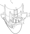
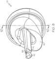
- the main body 12 comprises an outer flow surface 106 and an inner flow surface 108, for example as shown in FIGs. 6 and 13 .
- the dispensing port 20 forms an opening in the outer flow surface 106.
- the main body 12 comprises one or more finger holds 70, for example two finger holds 70, which can be oriented in any suitable orientation.
- the finger holds 70 are configured such that the user's index finger is placed between one of the finger holds 70, for example70a, and the flange 22 and the user's middle finger is placed between the other of the finger holds, for example 70b, and the flange 22. In this way, the user's thumb is used to depress the dome member 16 ( FIG. 13 ) to dispense fluid.
- the main body 12 has one or more detents 72 ( FIGs. 1 , 5 , 7 ).
- the detents 72 retain the cap 14 ( FIG. 12 ) until the cap 14 is removed, as discussed below.
- Some embodiments of the main body 12 have two opposing detents 72, which can take on any suitable configuration.
- the detents 72 are openings extending through a portion of the respective finger hold 70a, 70b.
- FIG. 10 is a cross-sectional view of the valve member 18.
- the stem 38 has a generally triangular cross-section, corresponding to the cross-section of the opening 62 of the main body 12 ( FIG. 7 ).
- the keeper 52 is located at a distal end of the stem 38. Just proximal of the keeper 52 is a narrowed portion 74 of the stem 38. The narrowed portion 74 fits into the catch 76 of the dome member 16 ( FIG. 4 ), thereby coupling the dome member 16 and the valve member 18 so that they move in tandem.
- the valve member 18 has a sealing surface 78 ( FIG. 10 ) which contacts the seal 32 ( FIG. 2 ) when the fluid dispenser 10 is in the sealed configuration 50. Due to the relatively large area of contact between the sealing surface 78 and the seal 32, the oxygen transmission rate into the fluid can be minimized. This is particularly important in certain industries, for example the wine industry.
- the valve member 18 has a face 80.
- the face 80 is angled relative to the longitudinal axis 81 of the stem 38. Further, the face 80 is configured to abut, or nearly abut, the dividing wall 66 ( FIG. 2 ) of the main body 12.
- the face 80 is angled relative to the longitudinal axis 81 of the stem 38 by an angle ⁇ , which is less than 90 degrees and, in some examples, is between 45 and 70 degrees. Angle ⁇ is measured between the longitudinal axis 81 and the face 80 from a location on the face 80 where the intermediate tubular portion 44 is at its longest (as measured parallel to the longitudinal axis 81 of the stem 38).
- the face 80 is angled relative to the valve seal plane 122 ( FIG. 10 ) by a non-zero angle ⁇ .
- the valve seal plane 122 is defined by a plane extending through the center of the sealing surface 78 along the periphery of the valve member 18. As illustrated in FIG. 10 , the valve seal plane 122 extends into and out of the page. In some embodiments, the angle ⁇ is between 20 and 45 degrees. In at least some embodiments, the longitudinal axis 81 is orthogonal to the valve seal plane 122.
- FIGs. 11 and 12 show an example of the cap 14.
- Some embodiments of the fluid dispenser 10 have the cap 14 affixed thereto until the fluid dispenser 10 is used to dispense fluid, at which time the cap 14, or at least a portion thereof, is removed to provide access to the dome member 16.
- the cap 14 is configured to show evidence of tampering and, in at least some examples, once it is removed from the main body 12, it cannot be easily reattached.
- the cap 14 has a tab 82, a body portion 84, and a bond strip 86. Extending from the body portion 84, the cap 14 comprises at least one ear 88. As illustrated in FIG. 12 , for example, the cap 14 has two ears 88. The ears 88 snap-fit into the detents 72 ( FIGs. 5 and 7 ) of the main body 12. Further, in some embodiments, the bond strip 86 is attached to a lip 92 ( FIG. 5 ) of the main body 12. The bond strip 86 can be attached to the lip 92 in any desirable way, for example with adhesive or via ultrasonic welding. In some embodiments, the bond strip 86 has a plurality of teeth 94 ( FIG. 12 ) which provide contact points to contact the lip 92. The teeth 94 are flattened during ultrasonic welding, for example, to yield a high strength bond between the bond strip 86 and the lip 92.
- the cap 14 has at least one tear strip 90. As shown in FIG. 1 , for example, the cap 14 has two tear strips 90. In some examples, the tear strip(s) 90 extend entirely through the material of the body portion 84 along portion of length of the tear strip(s) 90. A shown in FIG. 11 , for example, the tear strips 90 extend through the material near where the tab 82 adjoins the body portion 84. With regard to FIG. 12 , as the tear strips 90 extend inwardly into the body portion 84 from the periphery of the cap 14, the tear strips 90 are thicker than nearer the periphery. Stated differently, the material thickness of the tear strips 90 increases along the length of the tear strip 90.
- the material thickness of the tear strips 90 is thinnest nearer the outer periphery of the cap 14. The thickness increases from the periphery until the tear strips 90 end at 96, where the material thickness of the tear strip(s) 90 is the same as the material thickness of the adjacent portion of the cap 14. Therefore, along a portion of the length of the tear strips 90, the tear strips 90 are reductions in the material thickness of the body portion 84.
- Removal of the cap 14, for example by a user wishing to dispense fluid from the fluid dispenser 10, is carried out by pulling on the tab 82.
- the tab 82 As the tab 82 is pulled, the tear strips 90 begin to tear along their length and cracks propagate until the tear strips 90 end at 96. At this point, the ears 88 snap out of the detents 72 and the dome member 16 is partially exposed to the user.
- the user continues to pull on the tab 82, at which point the cap 14 fractures at the attachment columns 98 ( FIG. 12 ). In this way, the bond strip 86 remains attached to the main body 12, and the body portion 84 and tab 82 of the cap 14 are removed from the bond strip 86 and are discarded.
- the user can dispense fluid by depressing the dome member 16, as shown in FIG. 13 , wherein the fluid dispenser 10 is in a flow configuration 104.
- the dome member 16 elastically deforms to take on the second configuration 102 when it is depressed.
- the dome member 16 consequently moves the valve member 18 inwardly and sealing contact between the seal 32 and the sealing surface 78 of the valve member 18 is broken.
- fluid is permitted to flow between the valve member 18 and the dividing wall 66 and out through the dispensing port 20.
- the fluid is further permitted to flow interiorly within the outer flow surface 106 and exteriorly to the inner flow surface 108 before exiting the fluid dispenser 10 via the dispensing port 20.
- a flow passage 124 ( FIG.
- the flow passage 124 is a slanted passage, relative to the longitudinal axis 81 ( FIG. 10 ), and at least a portion of the flow passage 124 extends 360 degrees around the stem 38.
- fluid is also permitted to flow past the guide 34, between the stem 38 and the guide 34, and into the chamber 68. Nonetheless, because the dome member 16 is sealed against the main body along recess 60, fluid is not permitted to exit the fluid dispenser 10 by any way other than through the dispensing port 20.
- the fluid dispenser 10 In order for the fluid to flow out of the fluid dispenser 10, it has to flow around the valve member 18. Due to the shape of the valve member 18, along with the guide 34 extending into the cavity 30, fluid must navigate a circuitous path. And, upon release of the dome member 16, the dome member 16 returns to its first configuration 100 ( FIG. 2 ), the sealing surface 78 again comes into contact with the seal 32, and flow of fluid out of the dispensing port 20 ceases. Further, upon release of the dome member 16 and closure of the valve member 18, the fluid dispenser 10 can eliminate dripping.
- flow of fluid out of the dispensing port 20 is reduced, however, upon release of the dome member 16 but prior to the sealing surface 78 sealing against seal 32. This is due in-part to the guide 34 extending a relatively long distance into the cavity 30. Further, because the inner tubular portion 40 overlaps a greater portion of the guide 34 at the bottom of the valve member 18 than at the top of the valve member 18, the flow of fluid around the valve member 18 is slowed prior to contact between the sealing surface 78 and the seal 32. And, in some embodiments, the face 80 is disposed at a non-zero angle, ⁇ , relative to a sealing plane 110 ( FIGs. 6 , 14 ) such that fluid flow is reduced prior to contact between the sealing surface 78 and the seal 32.
- the sealing plane 110 is defined by a plane extending through the center of the contact surface 126 of the seal 32 such that at each location around the periphery of the seal 32, the center of the contact surface 126 lies on the sealing plane 110.
- the contact surface 126 is the surface of the seal 32 that mates with the sealing surface 78 when the fluid dispenser 10 is in the sealed configuration 50 ( FIG. 14 ).
- the non-zero angle ⁇ is between 20 and 45 degrees.
- the fluid dispenser 10 when the fluid dispenser 10 is in the sealed configuration 50, there is no head pressure from the fluid within the container pushing outwardly on the dome member 16 because the sealing surface 78 and seal 32 are disposed between the dome member 16 and the fluid in the container. Additionally, head pressure from the fluid tends to aid in closing the fluid dispenser 10 by pushing the valve member 18 into the seal 32 of the main body 12.
- FIG. 14 a detailed cross-sectional view of a portion of the valve member 18 is shown with a portion of the main body 12. As shown, the fluid dispenser 10 is in the sealed configuration 50.
- the outer tubular portion 48 has a lobe 112 ( FIGs. 10 and 14 ) that contacts the seal 32.
- the lobe 112 moves toward the seal 32, ultimately sliding along incline 114 of the seal 32. Subsequently, the lobe 112 moves past the incline 114 until the valve member 18 comes to rest against the main body 12 such that the sealing surface 78 contacts the contact surface 126.
- the outer tubular portion 48 pushes the seal 32 inwardly toward the intermediate tubular portion 44.
- the intermediate tubular portion 44 comprises a wedge 116.
- the wedge 116 comes into contact with the distal most end of the seal 32.
- the wedge 116 contacts on opposite side of the seal 32 than the lobe 112. This arrangement prevents creep and deformation of the seal 32 over time in order to ensure proper sealing of the fluid dispenser 10, even after a period of shelf time or use.
- the seal 32 is prevented from undergoing too much deformation because it is situated between the wedge 116 and lobe 112.
- the lobe 112 and shape of the seal 32 and valve member 18 provide a relatively large area of contact between the seal 32 and valve member 18, thereby reducing the oxygen transmission rate of the fluid dispenser 10.
- a capillary gap 118 is disposed between the valve member 18 and the guide 34. The presence of the capillary gap 118 eliminates post-closure dripping.
- the main body 12 is made of HDPE (high density polyethylene), although other materials are also suitable.
- the valve member 18 is made of HDPE, though other materials are also suitable.
- the cap 14 is made of HDPE, though other materials are also suitable.
- the main body 12, valve member 18, and cap 14 can all be made from the same HDPE or different HDPEs, for example having different hardnesses.
- the dome member 16 is made of a TPE (thermoplastic elastomer), although other materials can also be used.
- TPE thermoplastic elastomer
- the various components can be injection molded and assembled.
- At least some examples of the fluid dispenser 10 are assembled by inserting the valve member 18 into the main body 12 such that stem 38 extends through the guide 34 ( FIG. 2 ).
- the valve member 18 can be inserted into the main body 12 until it bottoms against the main body 12.
- the dome member 16 is added to the main body 12 by inserting the keeper 52 ( FIG. 10 ) into the retainer 54 ( FIG. 4 ).
- the dome member 16 is seated against the recess 60 ( FIG. 7 ).
- the cap 14 is added by placing the ears 88 ( FIG. 11 ) within the detents 72 ( FIG. 5 ); the bond strip 86 ( FIG. 12 ) is pressed against the lip 92 ( FIG. 5 ) and the two are ultrasonically welded together.
- the dome member 16 even when the dome member 16 is in the first configuration 100 ( FIG. 2 ), it continues to exert an outward (closing) force against the valve member 18. This helps to ensure sealing between the valve member 18 and the main body 12 as well as between the dome member 16 and the main body 12.
- the coupler 24 can have any desired length or configuration.
- the coupler 24 can be configured to attach to a bag-in-box container, bag container, box container, or any other container with standardized or non-standardized shape.
- some embodiments of the fluid dispenser 10 can utilize dome members 16 formed of a clear material, for example to allow the color of the fluid to be seen.
- the dome member 16 is made from a colored material which can also be used to signify the type or flavor of fluid.
- At least a portion of the valve member 18 extends over at least a portion of the dispensing port 20 prior to sealing of the valve member 20 against the seal 32. In this way, the flow of fluid can be throttled and/or reduced prior to closure of fluid dispenser 10.
- FIGs. 15-17 show another example of a fluid dispenser 10.
- the fluid dispenser 10 has a spout 134.
- fluid is dispensed from the fluid dispenser 10 via the spout 134.
- the spout 134 extends downwardly from the main body 12. Further, the spout 134 can extend away from the flange 22, permitting the user to position a rim of drinking vessel (e.g., glass or cup) between the flange 22 and the spout 134, thereby reducing the likelihood of spillage.
- a rim of drinking vessel e.g., glass or cup
- the body 12 comprises a barrel 136.
- the barrel 136 extends from the flange 22 and provides a greater distance between flange 22 and the dispensing port 20, for example when compared to the embodiment shown in FIG. 2 .
Description
- Heretofore, various types of fluid dispensers have been developed to dispense fluid from various types of containers. A dispenser is for instance known from
FR 2 832 702 A1 WO 2011/162788 A1 . Known types of fluid dispensers can suffer from a variety of problems: dripping after closure and oxygen transmission through the fluid dispenser and into the container are examples of the problems. Oxygen transmission into the fluid within the container can lead to reduced freshness or taste due to oxidation of the fluid. This phenomenon is particularly acute in the wine industry. - Consequently, there remains a need for a fluid dispenser that has a low oxygen transmission rate and does not drip after closure.
- Without limiting the scope of the invention a brief summary of some of the claimed embodiments of the invention is set forth below. Additional details of the summarized embodiments of the invention and/or additional embodiments of the invention may be found in the Detailed Description of the Invention, below.
- Object of the invention is a fluid dispenser according to claim 1.
- In some embodiments, the valve member is sildable within the main body.
- The valve member further has a channel therein; the channel has a first sidewall and a second sidewall opposite the first sidewall. When the valve member is in the closed position, the seal extends into the channel and contacts the first and second sidewalls. The main body and valve member define a second opening and flow passage therebetween. When the valve member is in the open position, the flow passage extends from the first opening to the second opening and when the valve portion is in the closed position, the flow passage is sealed by contact between the seal and at least the first sidewall.
- In some embodiments, the flow passage includes a section which extends 360 degrees about the stem and is bounded by the main body and the valve member. The flow passage is a slanted passage which slants relative to the longitudinal axis of the stem.
-
-
FIG. 1 shows a 3-dimensional view of an example of a fluid dispenser. -
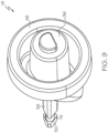
FIG. 2 shows a cutaway view of the fluid dispenser ofFIG. 1 . -
FIG. 3 shows a 3-dimensional view of an example of a dome member. -
FIG. 4 shows a cutaway view of the dome member ofFIG. 3 . -
FIG. 5 shows a cutaway view of an example of a main body of the fluid dispenser ofFIG. 2 . -
FIG. 6 shows another cutaway view of an example of a main body of the fluid dispenser ofFIG. 2 . -
FIG. 7 shows a 3-dimensional view of the front of a main body of the fluid dispenser ofFIG. 2 . -
FIG. 8 shows a 3-dimensional view of an example of the valve member. -
FIG. 9 shows a 3-dimensional view of an example of the valve member ofFIG. 8 . -
FIG. 10 shows a cutaway view of the valve member ofFIGs. 8 and9 . -
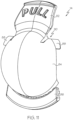
FIG. 11 shows a 3-dimensional view of an example of a cap. -
FIG. 12 shows 3-dimensional view of an example of the cap ofFIG. 11 . -
FIG. 13 shows a cutaway view of the fluid dispenser ofFIG. 2 in an open or flow configuration. -
FIG. 14 shows a detailed cutaway view of the valve member and body ofFIG. 13 . -
FIG. 15 shows a 3-dimensional view of an example of a fluid dispenser. -
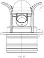
FIG. 16 shows a cutaway view of the fluid dispenser ofFIG. 15 . -
FIG. 17 shows a bottom view of the fluid dispenser ofFIGS. 15 and16 . - A fluid dispenser comprises a main body, a valve member and a dome member. The valve member is coupled to the dome member and is movable within the main body such that upon depression of the dome member, fluid can flow out of the fluid dispenser.
- With regard to
FIG. 1 , themain body 12 of thefluid dispenser 10 is shown with acap 14 attached thereto. In some embodiments, thecap 14 protects the dome member 16 (FIG. 2 ) and, prior to removal of thecap 14, shows evidence of tampering. As shown inFIG. 2 , which is a cross-sectional view, thedome member 16 is coupled to avalve member 18. Thevalve member 18 is slidable within themain body 12 such that when thedome member 16 is pressed, fluid can flow out of a dispensingport 20. - In some embodiments, the
main body 12 has aflange 22 and acoupler 24. Thecoupler 24 is configured to attach themain body 12 to a container (not shown) in order to dispense fluid from the container via thefluid dispenser 10. In some embodiments, thecoupler 24 has one or more ribs orbeads 26 extending radially outwardly in order to provide a seal between the outlet (e.g., spout) of the container and thecoupler 24. As shown, thebeads 26 are provided on the outside of thecoupler 24 such that thecoupler 24 can be inserted into a female connection on the container. Other configurations are also contemplated, however. For example, thebeads 26 can be disposed on the inside of thecoupler 24. Further, thecoupler 24 can have interior and/or exterior threads or any other suitable attachment or sealing mechanism. Thecoupler 24 can also be attached to a screw ring which can be attached to the container (not shown). In some embodiments, thecoupler 24 includes threebeads 26; however, any suitable number can be employed, for example 1, 2, 3, 4, 5, 6, 7 or more. Additionally, wheremultiple beads 26 are used, thebeads 26 can be spaced apart from one another and spaced from theflange 22 and coupler end 28 (FIG. 2 ) in any suitable arrangement. - As further shown in
FIG. 2 , themain body 12 defines acavity 30 which is partially bounded by thecoupler 24. Further, in some embodiments, themain body 12 comprises aseal 32 that extends into thecavity 30. In some embodiments, themain body 12 comprises aguide 34 through which a portion of thevalve member 18 extends. - The
valve member 18 comprises abase portion 36, astem 38 extending from thebase portion 36, an innertubular portion 40, an inner facingwall 42, and intermediatetubular portion 44, an outer facingwall 46, and an outertubular portion 48. In some embodiments, the length of the intermediatetubular portion 44 varies around the periphery of thevalve member 18. For example, in some embodiments, the intermediatetubular portion 44 is longer at the bottom of thevalve member 18 than at the top of thevalve member 18, as shown inFIGs. 2 and10 . In some embodiments, the length of the innertubular portion 40 varies around the periphery of thevalve member 18; for example, the length of the innertubular portion 40 may be longer at the bottom of thevalve member 18 than at the top of thevalve member 18, as further shown inFIGs. 2 and10 . In some embodiments, the length of the intermediatetubular portion 44 is longer closer to the dispensing port 20 (FIG. 2 ) than further away from thedispensing port 20. - As shown in
FIG. 2 , the outertubular portion 48 contacts theseal 32 of themain body 12 when thefluid dispenser 10 is in a sealedconfiguration 50, wherein fluid is prevented from flowing out of thefluid dispenser 10. - In some embodiments, a first channel 128 (
FIG. 10 ) is formed between at least a portion of thestem 38 and at least a portion of the innertubular portion 40. In some embodiments, asecond channel 130 is formed between at least a portion of the innertubular portion 40 and at least a portion of the intermediatetubular portion 44; the second channel may be further bounded by the inner facingwall 42. In some embodiments, athird channel 132 is formed between at least a portion of the intermediatetubular portion 44 and at least a portion of the outertubular portion 48; the third channel may be further bounded by the outer facingwall 46, as shown for example inFIG. 10 . In at least some embodiments, the first andthird channels second channel 130. - Although shown in
FIGs. 2 and10 with thevalve member 18 having a third channel into which theseal 32 extends, it will be appreciated that the relationship can be reversed such that themain body 12 comprises a channel into which a portion of thevalve member 18 extends. - The
valve member 18 further comprises akeeper 52 at the distal end portion of thestem 38. Thekeeper 52 interfaces with aretainer 54 of thedome member 16. Thekeeper 52 couples thevalve member 18 to thedome member 16 such that thevalve member 18 anddome member 16 move in tandem. - With regard to
FIGs. 3 and4 , thedome member 16 is shown therein in greater detail. InFIG. 4 , thedome member 16 is shown in cross-section. Thedome member 16 has abase 56. In some examples, as shown inFIGs. 3 and4 , thebase 56 is circular. Other shapes and configurations are also contemplated, however; for example, thebase 56 can also be square, rectangular, hexagonal, octagonal, or in the shape of any other suitable polygon. In some embodiments, the cross-section of material is thicker at thebase 56 of thedome member 16 than nearer the peak of thedome member 16. At least some examples of the base 56 have aseat 58, which is configured to be received by the recess 60 (FIGs. 5 and7 ). - In at least some examples, the
dome member 16 comprises an elastomeric material. Thedome member 16 is elastically deformable from a first configuration 100 (FIG. 2 ), wherein thefluid dispenser 10 is in a sealedconfiguration 50, to a second configuration 102 (FIG. 13 ), in which fluid is permitted to flow out of thefluid dispenser 10. Thedome member 16 is predisposed to remain in thefirst configuration 100 unless a force is applied to it to depress thedome member 16. Thus, thedome member 16 pulls thevalve member 18 closed, viakeeper 52, as long thedome member 16 is not depressed. - Turning to
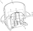
FIG. 5 , an example of themain body 12 is shown in the absence of thedome member 16,valve member 18, andcap 14. As shown, theguide 34 defines anopening 62 through which thestem 38 extends (FIG. 2 ). In some embodiments, theopening 62 is triangular in cross-section. Referring toFIGs. 8 and9 , in some embodiments, thestem 38 has a triangular cross-section to correspond with the triangular cross-section of theguide 34. Theguide 34 can have any other suitable cross-sectional shape, for example circular, square, pentagonal, notched. - In some embodiments, the
main body 12 comprises one or more stand-offmembers 64. As illustrated inFIG. 5 , for example, a plurality of stand-offmembers 64 are employed. In some embodiments, the one or more stand-offmembers 64 are arranged to locate thedome member 16 within therecess 60. In some embodiments, the one or more stand-off members 64 (FIG. 5 ) abut the seat 58 (FIG. 4 ) of thedome member 16. Some examples of themain body 12 have at least three stand-offmembers 64. Some examples of themain body 12 have between three and fifteen stand-offmembers 64 and some embodiments have seven stand-offmembers 64, though any suitable number can be employed. Further, in at least some embodiments, the at least one stand-off member 64 is configured as a single stand-off member 64 having an annular shape; a semi-annular shape, for example with a segment cut out of it, can also be used. - With further regard to
FIGs. 5 and6 , in some examples, themain body 12 has a dividingwall 66, separating thecavity 30 from thechamber 68. In some embodiments, the dividingwall 66 is oriented at a non-zero angle relative to a plane 120 (FIG. 5 ) defined by theflange 22. In some examples, themain body 12 comprises anouter flow surface 106 and aninner flow surface 108, for example as shown inFIGs. 6 and13 . In at least some examples, the dispensingport 20 forms an opening in theouter flow surface 106. - As shown in
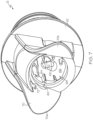
FIG. 7 , in some embodiments, themain body 12 comprises one or more finger holds 70, for example two finger holds 70, which can be oriented in any suitable orientation. As illustrated, the finger holds 70 are configured such that the user's index finger is placed between one of the finger holds 70, for example70a, and theflange 22 and the user's middle finger is placed between the other of the finger holds, for example 70b, and theflange 22. In this way, the user's thumb is used to depress the dome member 16 (FIG. 13 ) to dispense fluid. - In at least some examples, the
main body 12 has one or more detents 72 (FIGs. 1 ,5 ,7 ). In some embodiments, thedetents 72 retain the cap 14 (FIG. 12 ) until thecap 14 is removed, as discussed below. Some embodiments of themain body 12 have two opposingdetents 72, which can take on any suitable configuration. In some examples, thedetents 72 are openings extending through a portion of therespective finger hold - Turning to
FIGs. 8-10 , thevalve member 18 is shown in detail;FIG. 10 is a cross-sectional view of thevalve member 18. As illustrated, in some examples, thestem 38 has a generally triangular cross-section, corresponding to the cross-section of theopening 62 of the main body 12 (FIG. 7 ). Further, in some examples, thekeeper 52 is located at a distal end of thestem 38. Just proximal of thekeeper 52 is a narrowedportion 74 of thestem 38. The narrowedportion 74 fits into thecatch 76 of the dome member 16 (FIG. 4 ), thereby coupling thedome member 16 and thevalve member 18 so that they move in tandem. - The
valve member 18 has a sealing surface 78 (FIG. 10 ) which contacts the seal 32 (FIG. 2 ) when thefluid dispenser 10 is in the sealedconfiguration 50. Due to the relatively large area of contact between the sealingsurface 78 and theseal 32, the oxygen transmission rate into the fluid can be minimized. This is particularly important in certain industries, for example the wine industry. - With further regard to
FIGs. 8 and10 , thevalve member 18 has aface 80. In some examples, theface 80 is angled relative to thelongitudinal axis 81 of thestem 38. Further, theface 80 is configured to abut, or nearly abut, the dividing wall 66 (FIG. 2 ) of themain body 12. In some embodiments, theface 80 is angled relative to thelongitudinal axis 81 of thestem 38 by an angle α, which is less than 90 degrees and, in some examples, is between 45 and 70 degrees. Angle α is measured between thelongitudinal axis 81 and theface 80 from a location on theface 80 where the intermediatetubular portion 44 is at its longest (as measured parallel to thelongitudinal axis 81 of the stem 38). In some embodiments, theface 80 is angled relative to the valve seal plane 122 (FIG. 10 ) by a non-zero angle δ. Thevalve seal plane 122 is defined by a plane extending through the center of the sealingsurface 78 along the periphery of thevalve member 18. As illustrated inFIG. 10 , thevalve seal plane 122 extends into and out of the page. In some embodiments, the angle δ is between 20 and 45 degrees. In at least some embodiments, thelongitudinal axis 81 is orthogonal to thevalve seal plane 122. -
FIGs. 11 and12 show an example of thecap 14. Some embodiments of thefluid dispenser 10 have thecap 14 affixed thereto until thefluid dispenser 10 is used to dispense fluid, at which time thecap 14, or at least a portion thereof, is removed to provide access to thedome member 16. Thecap 14 is configured to show evidence of tampering and, in at least some examples, once it is removed from themain body 12, it cannot be easily reattached. - The
cap 14 has atab 82, abody portion 84, and abond strip 86. Extending from thebody portion 84, thecap 14 comprises at least oneear 88. As illustrated inFIG. 12 , for example, thecap 14 has twoears 88. Theears 88 snap-fit into the detents 72 (FIGs. 5 and7 ) of themain body 12. Further, in some embodiments, thebond strip 86 is attached to a lip 92 (FIG. 5 ) of themain body 12. Thebond strip 86 can be attached to thelip 92 in any desirable way, for example with adhesive or via ultrasonic welding. In some embodiments, thebond strip 86 has a plurality of teeth 94 (FIG. 12 ) which provide contact points to contact thelip 92. Theteeth 94 are flattened during ultrasonic welding, for example, to yield a high strength bond between thebond strip 86 and thelip 92. - In some embodiments, the
cap 14 has at least onetear strip 90. As shown inFIG. 1 , for example, thecap 14 has two tear strips 90. In some examples, the tear strip(s) 90 extend entirely through the material of thebody portion 84 along portion of length of the tear strip(s) 90. A shown inFIG. 11 , for example, the tear strips 90 extend through the material near where thetab 82 adjoins thebody portion 84. With regard toFIG. 12 , as the tear strips 90 extend inwardly into thebody portion 84 from the periphery of thecap 14, the tear strips 90 are thicker than nearer the periphery. Stated differently, the material thickness of the tear strips 90 increases along the length of thetear strip 90. The material thickness of the tear strips 90 is thinnest nearer the outer periphery of thecap 14. The thickness increases from the periphery until the tear strips 90 end at 96, where the material thickness of the tear strip(s) 90 is the same as the material thickness of the adjacent portion of thecap 14. Therefore, along a portion of the length of the tear strips 90, the tear strips 90 are reductions in the material thickness of thebody portion 84. - Removal of the
cap 14, for example by a user wishing to dispense fluid from thefluid dispenser 10, is carried out by pulling on thetab 82. As thetab 82 is pulled, the tear strips 90 begin to tear along their length and cracks propagate until the tear strips 90 end at 96. At this point, theears 88 snap out of thedetents 72 and thedome member 16 is partially exposed to the user. To remove thecap 14 entirely, such that thefluid dispenser 10 can be utilized, the user continues to pull on thetab 82, at which point thecap 14 fractures at the attachment columns 98 (FIG. 12 ). In this way, thebond strip 86 remains attached to themain body 12, and thebody portion 84 andtab 82 of thecap 14 are removed from thebond strip 86 and are discarded. - With the
cap 14 removed, the user can dispense fluid by depressing thedome member 16, as shown inFIG. 13 , wherein thefluid dispenser 10 is in aflow configuration 104. In some examples, thedome member 16 elastically deforms to take on thesecond configuration 102 when it is depressed. Thedome member 16 consequently moves thevalve member 18 inwardly and sealing contact between theseal 32 and the sealingsurface 78 of thevalve member 18 is broken. As such, fluid is permitted to flow between thevalve member 18 and the dividingwall 66 and out through the dispensingport 20. The fluid is further permitted to flow interiorly within theouter flow surface 106 and exteriorly to theinner flow surface 108 before exiting thefluid dispenser 10 via the dispensingport 20. A flow passage 124 (FIG. 13 ) extends from thecavity 30 and is at least partially bounded by thevalve member 18 and main body 12 (e.g.,outer flow surface 106, inner flow surface 108). In at least some embodiments, theflow passage 124 is a slanted passage, relative to the longitudinal axis 81 (FIG. 10 ), and at least a portion of theflow passage 124 extends 360 degrees around thestem 38. - Moreover, it will be appreciated that fluid is also permitted to flow past the
guide 34, between thestem 38 and theguide 34, and into thechamber 68. Nonetheless, because thedome member 16 is sealed against the main body alongrecess 60, fluid is not permitted to exit thefluid dispenser 10 by any way other than through the dispensingport 20. - In order for the fluid to flow out of the
fluid dispenser 10, it has to flow around thevalve member 18. Due to the shape of thevalve member 18, along with theguide 34 extending into thecavity 30, fluid must navigate a circuitous path. And, upon release of thedome member 16, thedome member 16 returns to its first configuration 100 (FIG. 2 ), the sealingsurface 78 again comes into contact with theseal 32, and flow of fluid out of the dispensingport 20 ceases. Further, upon release of thedome member 16 and closure of thevalve member 18, thefluid dispenser 10 can eliminate dripping. - In some examples, flow of fluid out of the dispensing
port 20 is reduced, however, upon release of thedome member 16 but prior to the sealingsurface 78 sealing againstseal 32. This is due in-part to theguide 34 extending a relatively long distance into thecavity 30. Further, because the innertubular portion 40 overlaps a greater portion of theguide 34 at the bottom of thevalve member 18 than at the top of thevalve member 18, the flow of fluid around thevalve member 18 is slowed prior to contact between the sealingsurface 78 and theseal 32. And, in some embodiments, theface 80 is disposed at a non-zero angle, θ, relative to a sealing plane 110 (FIGs. 6 ,14 ) such that fluid flow is reduced prior to contact between the sealingsurface 78 and theseal 32. The sealing plane 110 is defined by a plane extending through the center of thecontact surface 126 of theseal 32 such that at each location around the periphery of theseal 32, the center of thecontact surface 126 lies on the sealing plane 110. Thecontact surface 126 is the surface of theseal 32 that mates with the sealingsurface 78 when thefluid dispenser 10 is in the sealed configuration 50 (FIG. 14 ). In some embodiments, the non-zero angle θ is between 20 and 45 degrees. When thefluid dispenser 10 is in the sealedconfiguration 50, the sealing plane 110 and thevalve seal plane 122 are coincident. - In at least some examples, when the
fluid dispenser 10 is in the sealedconfiguration 50, there is no head pressure from the fluid within the container pushing outwardly on thedome member 16 because the sealingsurface 78 andseal 32 are disposed between thedome member 16 and the fluid in the container. Additionally, head pressure from the fluid tends to aid in closing thefluid dispenser 10 by pushing thevalve member 18 into theseal 32 of themain body 12. - With regard to
FIG. 14 , a detailed cross-sectional view of a portion of thevalve member 18 is shown with a portion of themain body 12. As shown, thefluid dispenser 10 is in the sealedconfiguration 50. - In some examples, the outer
tubular portion 48 has a lobe 112 (FIGs. 10 and14 ) that contacts theseal 32. As thevalve member 18 is closed, thelobe 112 moves toward theseal 32, ultimately sliding alongincline 114 of theseal 32. Subsequently, thelobe 112 moves past theincline 114 until thevalve member 18 comes to rest against themain body 12 such that the sealingsurface 78 contacts thecontact surface 126. - Additionally, in some examples, the outer
tubular portion 48 pushes theseal 32 inwardly toward the intermediatetubular portion 44. In some embodiments, the intermediatetubular portion 44 comprises awedge 116. As thelobe 112 pushes the seal inwardly toward the intermediatetubular portion 44, thewedge 116 comes into contact with the distal most end of theseal 32. Thewedge 116 contacts on opposite side of theseal 32 than thelobe 112. This arrangement prevents creep and deformation of theseal 32 over time in order to ensure proper sealing of thefluid dispenser 10, even after a period of shelf time or use. Theseal 32 is prevented from undergoing too much deformation because it is situated between thewedge 116 andlobe 112. Moreover, thelobe 112 and shape of theseal 32 andvalve member 18 provide a relatively large area of contact between theseal 32 andvalve member 18, thereby reducing the oxygen transmission rate of thefluid dispenser 10. - In some examples, when the
fluid dispenser 10 is in the sealedconfiguration 50, as shown inFIG. 14 , acapillary gap 118 is disposed between thevalve member 18 and theguide 34. The presence of thecapillary gap 118 eliminates post-closure dripping. - In some embodiments, the
main body 12 is made of HDPE (high density polyethylene), although other materials are also suitable. Further, in some embodiments, thevalve member 18 is made of HDPE, though other materials are also suitable. In some embodiments, thecap 14 is made of HDPE, though other materials are also suitable. Themain body 12,valve member 18, and cap 14 can all be made from the same HDPE or different HDPEs, for example having different hardnesses. - In some examples, the
dome member 16 is made of a TPE (thermoplastic elastomer), although other materials can also be used. - Where plastics are used, the various components (e.g.,
dome member 16,main body 12,valve member 18, cap 14) can be injection molded and assembled. At least some examples of thefluid dispenser 10 are assembled by inserting thevalve member 18 into themain body 12 such thatstem 38 extends through the guide 34 (FIG. 2 ). Thevalve member 18 can be inserted into themain body 12 until it bottoms against themain body 12. Then, thedome member 16 is added to themain body 12 by inserting the keeper 52 (FIG. 10 ) into the retainer 54 (FIG. 4 ). Also, thedome member 16 is seated against the recess 60 (FIG. 7 ). Subsequently, thecap 14 is added by placing the ears 88 (FIG. 11 ) within the detents 72 (FIG. 5 ); the bond strip 86 (FIG. 12 ) is pressed against the lip 92 (FIG. 5 ) and the two are ultrasonically welded together. - In at least some examples, even when the
dome member 16 is in the first configuration 100 (FIG. 2 ), it continues to exert an outward (closing) force against thevalve member 18. This helps to ensure sealing between thevalve member 18 and themain body 12 as well as between thedome member 16 and themain body 12. - As will be appreciated, the
coupler 24 can have any desired length or configuration. Thecoupler 24 can be configured to attach to a bag-in-box container, bag container, box container, or any other container with standardized or non-standardized shape. - Further, some embodiments of the
fluid dispenser 10 can utilizedome members 16 formed of a clear material, for example to allow the color of the fluid to be seen. In some examples, thedome member 16 is made from a colored material which can also be used to signify the type or flavor of fluid. - In at least some examples of the
fluid dispenser 10, at least a portion of the valve member 18 (e.g., intermediate tubular portion 44) extends over at least a portion of the dispensingport 20 prior to sealing of thevalve member 20 against theseal 32. In this way, the flow of fluid can be throttled and/or reduced prior to closure offluid dispenser 10. -
FIGs. 15-17 show another example of afluid dispenser 10. As shown, in some embodiments, thefluid dispenser 10 has aspout 134. In some embodiments, fluid is dispensed from thefluid dispenser 10 via thespout 134. In some embodiments, thespout 134 extends downwardly from themain body 12. Further, thespout 134 can extend away from theflange 22, permitting the user to position a rim of drinking vessel (e.g., glass or cup) between theflange 22 and thespout 134, thereby reducing the likelihood of spillage. - As further shown in
FIGs. 15-17 , in some embodiments, thebody 12 comprises abarrel 136. In some embodiments, thebarrel 136 extends from theflange 22 and provides a greater distance betweenflange 22 and the dispensingport 20, for example when compared to the embodiment shown inFIG. 2 . - A description of some embodiments of the stents and the delivery catheter are contained in one or more of the following numbered statements:
- Statement 1. A fluid dispenser having a flow configuration and a sealed configuration, the fluid dispenser comprising:
- a main body, the main body having an outer flow surface and an inner flow surface, the outer flow surface having an opening therethrough defining a dispensing port;
- a dome member; and
- a valve member, the valve member having a face and being coupled to the dome member;
- wherein, when the fluid dispenser is in the flow configuration, the outer flow surface, inner flow surface, and face define a fluid passageway for fluid to flow exteriorly to the inner flow surface, interiorly to the outer flow surface, and exit the fluid dispenser via the dispensing port.
- Statement 2. The fluid dispenser of statement 1, wherein the valve member further comprises a stem, the stem being coupled to the dome member.
- Statement 3. The fluid dispenser of statement 2, wherein the main body comprises a guide through which the stem extends.
-
Statement 4. The fluid dispenser of statement 3, wherein the guide comprises the inner flow surface. - Statement 5. The fluid dispenser of statement 1, wherein at least a portion of the outer flow surface is in opposing relationship with the inner flow surface.
- Statement 6. The fluid dispenser of statement 1, wherein the main body has a seal and the valve member has an outer tubular portion, the outer tubular portion contacting the seal when the fluid dispenser is in the sealed configuration.
- Statement 7. The fluid dispenser of statement 6, wherein the valve member has an intermediate tubular portion and the seal is disposed between the outer tubular portion and the intermediate tubular portion when the fluid dispenser is in the sealed configuration.
- Statement 8. The fluid dispenser of statement 7, wherein the valve member comprises a wedge extending from the intermediate tubular portion, the wedge configured to contact a side of the seal opposite the outer tubular portion.
- Statement 9. The fluid dispenser of statement 1, wherein the main body has a seal, the seal defining a sealing plane extending therethrough, the face angled with respect to the sealing plane at an angle between 20 and 45 degrees.
-
Statement 10. The fluid dispenser of statement 1, wherein the dome member is formed of an elastomeric material. - Statement 11. The fluid dispenser of statement 1, wherein the main body comprises a dividing wall, the face opposing the dividing wall.
-
Statement 12. The fluid dispenser of statement 1, wherein the main body has at least one stand-off member. - Statement 13. The fluid dispenser of
statement 12, wherein the at least one stand-off member defines a recess. -
Statement 14. The fluid dispenser of statement 13, wherein at least a portion of the dome member is seated against the recess. - Statement 15. The fluid dispenser of statement 1 further comprising a cap.
-
Statement 16. The fluid dispenser of statement 15, wherein the cap has at least one tear strip. - Statement 17. A fluid dispenser comprising:
- a main body having a sidewall with a first opening therein, and a seal;
- a valve member slidable within the main body, the valve member having an open position and a closed position, the valve member having a channel therein, the channel having a first sidewall and a second sidewall opposite the first sidewall, when the valve member is in the closed position, the seal extends into the channel and contacts the first and second sidewalls,
- the main body and valve member defining a second opening and flow passage therebetween, when the valve member is in the open position, the flow passage extending from the first opening to the second opening and when the valve portion is in the closed position, the flow passage being sealed by contact between the seal and at least the first sidewall.
-
Statement 18. The fluid dispenser of statement 17, wherein the second sidewall comprises a wedge extending into the channel. - Statement 19. The fluid dispenser of statement 17, wherein the first sidewall comprises a lobe.
-
Statement 20. A fluid dispenser comprising:- a main body having a sidewall with an opening therein through which fluid can be dispensed;
- an elastomeric dome member; and
- a movable valve member, the valve member movable between a sealed position and an open position, the valve member having a stem which is coupled to the elastomeric dome member, the stem having a longitudinal axis,
- in the open position the main body and valve member defining a flow passage which ends at the opening,
- wherein the flow passage includes a section which extends 360 degrees about the stem and is bounded by the main body and the valve member, the flow passage being a slanted passage which slants relative to the longitudinal axis of the stem.
- Statement 21. A fluid dispenser comprising:
- a main body having an opening therein through which fluid can be dispensed; and
- a movable valve member, the valve member movable between a sealed position and an open position,
- the valve member including:
- a base portion,
- a stem extending from the base portion,
- a first portion extending from the base and extending all the way around at least a portion of the stem,
- a first channel extending between the first portion and the stem,
- a second portion extending from the first portion, the second portion extending all the way around at least a portion of the stem,
- a third portion extending from the second portion, the third portion being annular and extending all the way around at least a portion of the stem,
- a second channel extending between the first, second, and third portions,
- a fourth portion extending outwardly from the third portion, the fourth portion being annular and extending all the way around at least a portion of the stem,
- a fifth portion extending from the fourth portion, the fifth portion being annular and extending all the way around at least a portion of the stem,
- a third channel extending between the third, fourth, and fifth portions,
- the main body including a first mating portion which, when the valve member is in the sealed position, extends into the third channel and contacts at least a portion of the fifth portion;
- a flow passage being formed between the main body and the valve member when the valve member is in the open position, the flow passage terminating at the opening;
- wherein the first and second channels are of decreasing depth as they extend about the stem away from the opening.
-
Statement 22. The fluid dispenser of statement 21, wherein the valve member is configured to mate with the main body such that in the open position, a fourth channel is defined between the second portion and the main body. - Statement 23. The fluid dispenser of statement 21, wherein the second channel faces an opposite direction than the first and third channels.
-
Statement 24. A fluid dispenser comprising:
a main body and a valve member, the main body having a seal, wherein one of the seal and valve member defines a channel and the other of the seal and valve member has a first surface and a second surface opposite the first surface, wherein when the fluid dispenser is in a closed configuration, the first and second surfaces contact opposing surfaces of the channel. - Statement 25. The fluid dispenser of
statement 24, wherein the contact between the seal and valve member extends 360 degrees around the longitudinal axis of the valve member. -
Statement 26. The fluid dispenser ofstatement 24 or statement 25, wherein the valve member can be any one of the valve members disclosed herein. - Statement 27. The fluid dispenser of any one of
statements -
Statement 28. The fluid dispenser of any one of statements 24-27, wherein one of the opposing surfaces of the channel forms a wedge, for example as shown inFIG. 14 viareference numeral 116. - The above disclosure is intended to be illustrative and not exhaustive. This description will suggest many variations and alternatives to one of ordinary skill in this field of art. All these alternatives and variations are intended to be included within the scope of the claims where the term "comprising" means "including, but not limited to." Those familiar with the art may recognize other equivalents to the specific embodiments described herein which equivalents are also intended to be encompassed by the claims.
- Further, the particular features presented in the dependent claims can be
- Those skilled in the art may recognize other equivalents to the specific embodiment described herein which equivalents are encompassed by the claims attached hereto.
Claims (17)
- A fluid dispenser (10) having a flow configuration and a sealed configuration, the fluid dispenser (10) comprising a main body (12), a dome member (16) such that, upon depression of the dome member (16), fluid can flow out of the fluid dispenser, and a valve member (18), characterized in that:the main body (12) has at least a portion of an outer flow surface (106) in opposing relationship with an inner flow surface (108), the outer flow surface (106) having an opening therethrough defining a dispensing port (20); andthe valve member (18) comprising a base portion (36), a stem (38) extending from the base portion (36), an inner tubular portion (40), an inner facing wall (42), an intermediate tubular portion (44), an outer facing wall (46), an outer tubular portion (48), a face (80) and a keeper (52) at a distal end portion of the stem (38) and interfacing with a retainer (54) of the dome member (16) to couple the valve member (18) to the dome member (16) such that the valve member (18) and dome member (16) move in tandem; andwhen the fluid dispenser (10) is in the flow configuration, the outer flow surface (106), inner flow surface (108), face (80) and base portion (36) define a fluid passageway for fluid to flow exteriorly to the inner flow surface (108), interiorly to the outer flow surface (106), and exit the fluid dispenser (10) via the dispensing port (20); andthe main body (12) has a seal (32), the seal (32) defining a sealing plane (122) extending therethrough, the face (80) of the valve member (18) being angled with respect to the sealing plane at an angle between 20 and 45 degrees.
- A fluid dispenser (10) according to claim 1, wherein the main body (12) comprises a guide (34) through which the stem (38) extends.
- A fluid dispenser (10) according to claim 2, wherein the guide (34) comprises the inner flow surface (108).
- A fluid dispenser (10) according to one of claims 1 to 3, wherein the main body (12) has a seal (32), the outer tubular portion (48) contacting the seal (32) when the fluid dispenser (10) is in the sealed configuration.
- A fluid dispenser (10) according to claim 4, wherein the seal (32) is disposed between the outer tubular portion (48) and the intermediate tubular portion (44) when the fluid dispenser (10) is in the sealed configuration.
- A fluid dispenser (10) according to claim 5, wherein the valve member (18) comprises a wedge (116) extending from the intermediate tubular portion (44), the wedge (116) configured to contact a side of the seal (32) opposite the outer tubular portion (48).
- A fluid dispenser (10) according to one of the claims 1 to 6, wherein the dome member (16) is formed of an elastomeric material.
- A fluid dispenser (10) according to one of the claims 1 to 7, wherein the main body (12) comprises a dividing wall (66), the face (80) opposing the dividing wall (66).
- A fluid dispenser (10) according to one of the claims 1 to 8, wherein the main body (12) has at least one stand-off member (64).
- A fluid dispenser (10) according to claim 9, wherein the at least one stand-off member (64) defines a recess (60).
- A fluid dispenser (10) according to claim 10, wherein at least a portion of the dome member (16) is seated against the recess (60).
- A fluid dispenser (10) according to one of the claims 1 to 11, further comprising a cap (14).
- A fluid dispenser (10) according to claim 12, wherein the cap (14) has at least one tear strip (90).
- A fluid dispenser (10) according to one of the claims 4 to 13, wherein the valve member (18) is slidable within the main body (12), the valve member having an open position and a closed position, the valve member (18) having a channel (132) therein, the channel (132) having a first sidewall (48) and a second sidewall (44) opposite the first sidewall, when the valve member (18) is in the closed position, the seal (32) extends into the channel (132) and contacts the first and second sidewalls; and
the main body (12) and valve member (18) defining a second opening and flow passage therebetween, when the valve member (18) is in the open position, the flow passage extending from the first opening to the second opening and when the valve member (18) is in the closed position, the flow passage being sealed by contact between the seal (32) and at least the first sidewall (48). - A fluid dispenser (10) according to claim 14, wherein the second sidewall (44) comprises a wedge (116) extending into the channel.
- A fluid dispenser (10) according to claim 15, wherein the first sidewall (48) comprises a lobe (112).
- A fluid dispenser (10) according one of the claims 7 to 16, wherein the valve member (18) is movable between a sealed position and an open position, the stem (38) having a longitudinal axis, in the open position the main body (12) and valve member (18) defining a flow passage which ends at the dispensing port (20), the flow passage includes a section which extends 360 degrees about the stem (38) and is bounded by the main body (12) and the valve member (18), the flow passage being a slanted passage which slants relative to the longitudinal axis of the stem (38)
Applications Claiming Priority (2)
| Application Number | Priority Date | Filing Date | Title |
|---|---|---|---|
| US201462002377P | 2014-05-23 | 2014-05-23 | |
| PCT/US2015/031926 WO2015179614A1 (en) | 2014-05-23 | 2015-05-21 | Liquid dispenser with valve |
Publications (3)
| Publication Number | Publication Date |
|---|---|
| EP3145856A1 EP3145856A1 (en) | 2017-03-29 |
| EP3145856B1 EP3145856B1 (en) | 2019-01-16 |
| EP3145856B2 true EP3145856B2 (en) | 2024-02-28 |
Family
ID=53488428
Family Applications (1)
| Application Number | Title | Priority Date | Filing Date |
|---|---|---|---|
| EP15731747.0A Active EP3145856B2 (en) | 2014-05-23 | 2015-05-21 | Liquid dispenser with valve |
Country Status (7)
| Country | Link |
|---|---|
| EP (1) | EP3145856B2 (en) |
| AU (1) | AU2015264101B2 (en) |
| CA (1) | CA2947623C (en) |
| ES (1) | ES2720248T3 (en) |
| MX (1) | MX2016014874A (en) |
| PT (1) | PT3145856T (en) |
| WO (1) | WO2015179614A1 (en) |
Families Citing this family (5)
| Publication number | Priority date | Publication date | Assignee | Title |
|---|---|---|---|---|
| WO2013142345A1 (en) | 2012-03-19 | 2013-09-26 | David S. Smith America, Inc., Dba, Worldwide Dispensers | Volume metering dispenser |
| USD766083S1 (en) | 2014-05-23 | 2016-09-13 | David S. Smith America, Inc. | Fluid dispenser |
| US20160304332A1 (en) | 2015-04-17 | 2016-10-20 | Ds Smith Plastics Limited | Multilayer film used with flexible packaging |
| WO2019023541A1 (en) * | 2017-07-28 | 2019-01-31 | David S. Smith America, Inc., Dba, Worldwide Dispensers | Front push tap |
| IT201900022887A1 (en) * | 2019-12-03 | 2020-03-03 | Vitop Moulding Srl | Automatic opening anti-tamper liquid dispenser tap |
Citations (6)
| Publication number | Priority date | Publication date | Assignee | Title |
|---|---|---|---|---|
| US4440316A (en) † | 1980-02-27 | 1984-04-03 | Trinity Associates | Combined piercer and valve for flexible bag |
| GB2169061A (en) † | 1983-02-07 | 1986-07-02 | Corrugated Prod Ltd | Bag and valve combination |
| WO1999036349A1 (en) † | 1998-01-16 | 1999-07-22 | Waddington & Duval Limited | Tap with incorporated air passageway |
| WO2006097704A1 (en) † | 2005-03-15 | 2006-09-21 | Ds Smith Plastics Ltd. | Tap with foil-piercing device for liquid containers |
| US20080105704A1 (en) † | 2006-11-06 | 2008-05-08 | Fres-Co System Usa, Inc. | Volumetric dispensing fitment and package including the same |
| WO2015142164A1 (en) † | 2014-03-18 | 2015-09-24 | Ipn Ip B.V. | Liquid dispensing tap and liquid container provided therewith |
Family Cites Families (9)
| Publication number | Priority date | Publication date | Assignee | Title |
|---|---|---|---|---|
| US855517A (en) * | 1906-05-16 | 1907-06-04 | Albert K Shauck | Valve. |
| ATE455076T1 (en) * | 2000-05-05 | 2010-01-15 | Procter & Gamble | MULTIPLE DIVIDED CONTAINER WITH TAP |
| FR2832702B1 (en) * | 2001-11-26 | 2004-04-09 | Flextainer | LIQUID DISPENSING TAP |
| US7455281B2 (en) * | 2006-10-03 | 2008-11-25 | Rubbermaid Incorporated | Spigot |
| ES2307448B1 (en) * | 2008-04-10 | 2009-10-13 | Shotave, S.A. | AUTOMATIC CLOSURE TAP FOR BAG TYPE CONTAINERS. |
| US20100296858A1 (en) | 2009-05-20 | 2010-11-25 | David S. Smith America, Inc. (D.B.A. Worldwide Dispensers) | Dispensing pen incorporating a dome spring element |
| EP2496514B1 (en) * | 2009-11-02 | 2013-09-11 | Illinois Tool Works Inc. | Tap assembly |
| US8459510B2 (en) | 2010-07-20 | 2013-06-11 | David S. Smith America, Inc. | Dispenser assembly |
| US8690026B2 (en) | 2011-10-25 | 2014-04-08 | David S. Smith America, Inc. | Fluid dispensing assembly |
-
2015
- 2015-05-21 ES ES15731747T patent/ES2720248T3/en active Active
- 2015-05-21 MX MX2016014874A patent/MX2016014874A/en unknown
- 2015-05-21 AU AU2015264101A patent/AU2015264101B2/en not_active Ceased
- 2015-05-21 PT PT15731747T patent/PT3145856T/en unknown
- 2015-05-21 WO PCT/US2015/031926 patent/WO2015179614A1/en active Application Filing
- 2015-05-21 CA CA2947623A patent/CA2947623C/en active Active
- 2015-05-21 EP EP15731747.0A patent/EP3145856B2/en active Active
Patent Citations (6)
| Publication number | Priority date | Publication date | Assignee | Title |
|---|---|---|---|---|
| US4440316A (en) † | 1980-02-27 | 1984-04-03 | Trinity Associates | Combined piercer and valve for flexible bag |
| GB2169061A (en) † | 1983-02-07 | 1986-07-02 | Corrugated Prod Ltd | Bag and valve combination |
| WO1999036349A1 (en) † | 1998-01-16 | 1999-07-22 | Waddington & Duval Limited | Tap with incorporated air passageway |
| WO2006097704A1 (en) † | 2005-03-15 | 2006-09-21 | Ds Smith Plastics Ltd. | Tap with foil-piercing device for liquid containers |
| US20080105704A1 (en) † | 2006-11-06 | 2008-05-08 | Fres-Co System Usa, Inc. | Volumetric dispensing fitment and package including the same |
| WO2015142164A1 (en) † | 2014-03-18 | 2015-09-24 | Ipn Ip B.V. | Liquid dispensing tap and liquid container provided therewith |
Non-Patent Citations (1)
| Title |
|---|
| Oxford Advanced Lerner’s Dictionary of Current English, Fifth edition. Editor Jonathan Crowther † |
Also Published As
| Publication number | Publication date |
|---|---|
| AU2015264101B2 (en) | 2019-09-19 |
| EP3145856A1 (en) | 2017-03-29 |
| CA2947623A1 (en) | 2015-11-26 |
| EP3145856B1 (en) | 2019-01-16 |
| AU2015264101A1 (en) | 2016-11-24 |
| WO2015179614A1 (en) | 2015-11-26 |
| ES2720248T3 (en) | 2019-07-19 |
| MX2016014874A (en) | 2017-04-06 |
| CA2947623C (en) | 2023-03-21 |
| PT3145856T (en) | 2019-05-09 |
Similar Documents
| Publication | Publication Date | Title |
|---|---|---|
| US10131530B2 (en) | Liquid dispenser with valve | |
| EP3145856B2 (en) | Liquid dispenser with valve | |
| KR101154716B1 (en) | Push-pull container closure | |
| AU2011379965B2 (en) | Fluid dispensing assembly | |
| US11014715B2 (en) | Safety cap spout | |
| EP2605980B1 (en) | High flow aerosol valve | |
| US20140263436A1 (en) | Container | |
| CN110225798B (en) | Product dispensing apparatus comprising a refill or assembly | |
| JP6065181B2 (en) | container | |
| JP2020516553A (en) | Packaging and dispensing assembly for fluid products with air return | |
| US10000316B2 (en) | One-way valve for a compressible container and container with such a valve | |
| US20200307886A1 (en) | Cap and cap-spout assembly | |
| WO2015002105A1 (en) | Container | |
| WO2015002101A1 (en) | Container | |
| JP3479521B2 (en) | Container and container spout and lid used for this container | |
| AU718270B2 (en) | Plastic stop-cock for liquid containers | |
| WO2021226325A1 (en) | High flow tap for dispensing fluids from a container | |
| US10266334B2 (en) | Barrier package aerosol container and piston for the same | |
| CN116495345A (en) | Lifting valve cover | |
| JP2019119453A (en) | Replacing container | |
| US20080023500A1 (en) | Connector for Bottle-Like Containers |
Legal Events
| Date | Code | Title | Description |
|---|---|---|---|
| STAA | Information on the status of an ep patent application or granted ep patent |
Free format text: STATUS: THE INTERNATIONAL PUBLICATION HAS BEEN MADE |
|
| PUAI | Public reference made under article 153(3) epc to a published international application that has entered the european phase |
Free format text: ORIGINAL CODE: 0009012 |
|
| STAA | Information on the status of an ep patent application or granted ep patent |
Free format text: STATUS: REQUEST FOR EXAMINATION WAS MADE |
|
| 17P | Request for examination filed |
Effective date: 20161221 |
|
| AK | Designated contracting states |
Kind code of ref document: A1 Designated state(s): AL AT BE BG CH CY CZ DE DK EE ES FI FR GB GR HR HU IE IS IT LI LT LU LV MC MK MT NL NO PL PT RO RS SE SI SK SM TR |
|
| AX | Request for extension of the european patent |
Extension state: BA ME |
|
| DAV | Request for validation of the european patent (deleted) | ||
| DAX | Request for extension of the european patent (deleted) | ||
| GRAP | Despatch of communication of intention to grant a patent |
Free format text: ORIGINAL CODE: EPIDOSNIGR1 |
|
| STAA | Information on the status of an ep patent application or granted ep patent |
Free format text: STATUS: GRANT OF PATENT IS INTENDED |
|
| INTG | Intention to grant announced |
Effective date: 20180806 |
|
| GRAS | Grant fee paid |
Free format text: ORIGINAL CODE: EPIDOSNIGR3 |
|
| GRAA | (expected) grant |
Free format text: ORIGINAL CODE: 0009210 |
|
| STAA | Information on the status of an ep patent application or granted ep patent |
Free format text: STATUS: THE PATENT HAS BEEN GRANTED |
|
| AK | Designated contracting states |
Kind code of ref document: B1 Designated state(s): AL AT BE BG CH CY CZ DE DK EE ES FI FR GB GR HR HU IE IS IT LI LT LU LV MC MK MT NL NO PL PT RO RS SE SI SK SM TR |
|
| REG | Reference to a national code |
Ref country code: GB Ref legal event code: FG4D |
|
| REG | Reference to a national code |
Ref country code: CH Ref legal event code: EP |
|
| REG | Reference to a national code |
Ref country code: IE Ref legal event code: FG4D |
|
| REG | Reference to a national code |
Ref country code: DE Ref legal event code: R096 Ref document number: 602015023629 Country of ref document: DE |
|
| REG | Reference to a national code |
Ref country code: AT Ref legal event code: REF Ref document number: 1089557 Country of ref document: AT Kind code of ref document: T Effective date: 20190215 |
|
| REG | Reference to a national code |
Ref country code: RO Ref legal event code: EPE |
|
| REG | Reference to a national code |
Ref country code: PT Ref legal event code: SC4A Ref document number: 3145856 Country of ref document: PT Date of ref document: 20190509 Kind code of ref document: T Free format text: AVAILABILITY OF NATIONAL TRANSLATION Effective date: 20190409 |
|
| REG | Reference to a national code |
Ref country code: NL Ref legal event code: MP Effective date: 20190116 |
|
| REG | Reference to a national code |
Ref country code: LT Ref legal event code: MG4D |
|
| PG25 | Lapsed in a contracting state [announced via postgrant information from national office to epo] |
Ref country code: NL Free format text: LAPSE BECAUSE OF FAILURE TO SUBMIT A TRANSLATION OF THE DESCRIPTION OR TO PAY THE FEE WITHIN THE PRESCRIBED TIME-LIMIT Effective date: 20190116 |
|
| REG | Reference to a national code |
Ref country code: AT Ref legal event code: MK05 Ref document number: 1089557 Country of ref document: AT Kind code of ref document: T Effective date: 20190116 |
|
| REG | Reference to a national code |
Ref country code: ES Ref legal event code: FG2A Ref document number: 2720248 Country of ref document: ES Kind code of ref document: T3 Effective date: 20190719 |
|
| PG25 | Lapsed in a contracting state [announced via postgrant information from national office to epo] |
Ref country code: PL Free format text: LAPSE BECAUSE OF FAILURE TO SUBMIT A TRANSLATION OF THE DESCRIPTION OR TO PAY THE FEE WITHIN THE PRESCRIBED TIME-LIMIT Effective date: 20190116 Ref country code: LT Free format text: LAPSE BECAUSE OF FAILURE TO SUBMIT A TRANSLATION OF THE DESCRIPTION OR TO PAY THE FEE WITHIN THE PRESCRIBED TIME-LIMIT Effective date: 20190116 Ref country code: SE Free format text: LAPSE BECAUSE OF FAILURE TO SUBMIT A TRANSLATION OF THE DESCRIPTION OR TO PAY THE FEE WITHIN THE PRESCRIBED TIME-LIMIT Effective date: 20190116 Ref country code: NO Free format text: LAPSE BECAUSE OF FAILURE TO SUBMIT A TRANSLATION OF THE DESCRIPTION OR TO PAY THE FEE WITHIN THE PRESCRIBED TIME-LIMIT Effective date: 20190416 Ref country code: FI Free format text: LAPSE BECAUSE OF FAILURE TO SUBMIT A TRANSLATION OF THE DESCRIPTION OR TO PAY THE FEE WITHIN THE PRESCRIBED TIME-LIMIT Effective date: 20190116 |
|
| PG25 | Lapsed in a contracting state [announced via postgrant information from national office to epo] |
Ref country code: IS Free format text: LAPSE BECAUSE OF FAILURE TO SUBMIT A TRANSLATION OF THE DESCRIPTION OR TO PAY THE FEE WITHIN THE PRESCRIBED TIME-LIMIT Effective date: 20190516 Ref country code: BG Free format text: LAPSE BECAUSE OF FAILURE TO SUBMIT A TRANSLATION OF THE DESCRIPTION OR TO PAY THE FEE WITHIN THE PRESCRIBED TIME-LIMIT Effective date: 20190416 Ref country code: RS Free format text: LAPSE BECAUSE OF FAILURE TO SUBMIT A TRANSLATION OF THE DESCRIPTION OR TO PAY THE FEE WITHIN THE PRESCRIBED TIME-LIMIT Effective date: 20190116 Ref country code: LV Free format text: LAPSE BECAUSE OF FAILURE TO SUBMIT A TRANSLATION OF THE DESCRIPTION OR TO PAY THE FEE WITHIN THE PRESCRIBED TIME-LIMIT Effective date: 20190116 Ref country code: GR Free format text: LAPSE BECAUSE OF FAILURE TO SUBMIT A TRANSLATION OF THE DESCRIPTION OR TO PAY THE FEE WITHIN THE PRESCRIBED TIME-LIMIT Effective date: 20190417 Ref country code: HR Free format text: LAPSE BECAUSE OF FAILURE TO SUBMIT A TRANSLATION OF THE DESCRIPTION OR TO PAY THE FEE WITHIN THE PRESCRIBED TIME-LIMIT Effective date: 20190116 |
|
| REG | Reference to a national code |
Ref country code: DE Ref legal event code: R026 Ref document number: 602015023629 Country of ref document: DE |
|
| PLBI | Opposition filed |
Free format text: ORIGINAL CODE: 0009260 |
|
| PLAX | Notice of opposition and request to file observation + time limit sent |
Free format text: ORIGINAL CODE: EPIDOSNOBS2 |
|
| PG25 | Lapsed in a contracting state [announced via postgrant information from national office to epo] |
Ref country code: DK Free format text: LAPSE BECAUSE OF FAILURE TO SUBMIT A TRANSLATION OF THE DESCRIPTION OR TO PAY THE FEE WITHIN THE PRESCRIBED TIME-LIMIT Effective date: 20190116 Ref country code: SK Free format text: LAPSE BECAUSE OF FAILURE TO SUBMIT A TRANSLATION OF THE DESCRIPTION OR TO PAY THE FEE WITHIN THE PRESCRIBED TIME-LIMIT Effective date: 20190116 Ref country code: AL Free format text: LAPSE BECAUSE OF FAILURE TO SUBMIT A TRANSLATION OF THE DESCRIPTION OR TO PAY THE FEE WITHIN THE PRESCRIBED TIME-LIMIT Effective date: 20190116 Ref country code: EE Free format text: LAPSE BECAUSE OF FAILURE TO SUBMIT A TRANSLATION OF THE DESCRIPTION OR TO PAY THE FEE WITHIN THE PRESCRIBED TIME-LIMIT Effective date: 20190116 Ref country code: CZ Free format text: LAPSE BECAUSE OF FAILURE TO SUBMIT A TRANSLATION OF THE DESCRIPTION OR TO PAY THE FEE WITHIN THE PRESCRIBED TIME-LIMIT Effective date: 20190116 Ref country code: AT Free format text: LAPSE BECAUSE OF FAILURE TO SUBMIT A TRANSLATION OF THE DESCRIPTION OR TO PAY THE FEE WITHIN THE PRESCRIBED TIME-LIMIT Effective date: 20190116 |
|
| 26 | Opposition filed |
Opponent name: SCHOLLE IPN IP B.V. Effective date: 20191015 |
|
| PG25 | Lapsed in a contracting state [announced via postgrant information from national office to epo] |
Ref country code: SM Free format text: LAPSE BECAUSE OF FAILURE TO SUBMIT A TRANSLATION OF THE DESCRIPTION OR TO PAY THE FEE WITHIN THE PRESCRIBED TIME-LIMIT Effective date: 20190116 |
|
| REG | Reference to a national code |
Ref country code: CH Ref legal event code: PL |
|
| GBPC | Gb: european patent ceased through non-payment of renewal fee |
Effective date: 20190521 |
|
| PG25 | Lapsed in a contracting state [announced via postgrant information from national office to epo] |
Ref country code: MC Free format text: LAPSE BECAUSE OF FAILURE TO SUBMIT A TRANSLATION OF THE DESCRIPTION OR TO PAY THE FEE WITHIN THE PRESCRIBED TIME-LIMIT Effective date: 20190116 Ref country code: CH Free format text: LAPSE BECAUSE OF NON-PAYMENT OF DUE FEES Effective date: 20190531 Ref country code: LI Free format text: LAPSE BECAUSE OF NON-PAYMENT OF DUE FEES Effective date: 20190531 |
|
| REG | Reference to a national code |
Ref country code: BE Ref legal event code: MM Effective date: 20190531 |
|
| PG25 | Lapsed in a contracting state [announced via postgrant information from national office to epo] |
Ref country code: LU Free format text: LAPSE BECAUSE OF NON-PAYMENT OF DUE FEES Effective date: 20190521 Ref country code: SI Free format text: LAPSE BECAUSE OF FAILURE TO SUBMIT A TRANSLATION OF THE DESCRIPTION OR TO PAY THE FEE WITHIN THE PRESCRIBED TIME-LIMIT Effective date: 20190116 |
|
| PLBB | Reply of patent proprietor to notice(s) of opposition received |
Free format text: ORIGINAL CODE: EPIDOSNOBS3 |
|
| PG25 | Lapsed in a contracting state [announced via postgrant information from national office to epo] |
Ref country code: TR Free format text: LAPSE BECAUSE OF FAILURE TO SUBMIT A TRANSLATION OF THE DESCRIPTION OR TO PAY THE FEE WITHIN THE PRESCRIBED TIME-LIMIT Effective date: 20190116 |
|
| PG25 | Lapsed in a contracting state [announced via postgrant information from national office to epo] |
Ref country code: GB Free format text: LAPSE BECAUSE OF NON-PAYMENT OF DUE FEES Effective date: 20190521 Ref country code: IE Free format text: LAPSE BECAUSE OF NON-PAYMENT OF DUE FEES Effective date: 20190521 |
|
| PG25 | Lapsed in a contracting state [announced via postgrant information from national office to epo] |
Ref country code: BE Free format text: LAPSE BECAUSE OF NON-PAYMENT OF DUE FEES Effective date: 20190531 |
|
| PG25 | Lapsed in a contracting state [announced via postgrant information from national office to epo] |
Ref country code: CY Free format text: LAPSE BECAUSE OF FAILURE TO SUBMIT A TRANSLATION OF THE DESCRIPTION OR TO PAY THE FEE WITHIN THE PRESCRIBED TIME-LIMIT Effective date: 20190116 |
|
| PG25 | Lapsed in a contracting state [announced via postgrant information from national office to epo] |
Ref country code: MT Free format text: LAPSE BECAUSE OF FAILURE TO SUBMIT A TRANSLATION OF THE DESCRIPTION OR TO PAY THE FEE WITHIN THE PRESCRIBED TIME-LIMIT Effective date: 20190116 Ref country code: HU Free format text: LAPSE BECAUSE OF FAILURE TO SUBMIT A TRANSLATION OF THE DESCRIPTION OR TO PAY THE FEE WITHIN THE PRESCRIBED TIME-LIMIT; INVALID AB INITIO Effective date: 20150521 |
|
| PLAY | Examination report in opposition despatched + time limit |
Free format text: ORIGINAL CODE: EPIDOSNORE2 |
|
| PG25 | Lapsed in a contracting state [announced via postgrant information from national office to epo] |
Ref country code: MK Free format text: LAPSE BECAUSE OF FAILURE TO SUBMIT A TRANSLATION OF THE DESCRIPTION OR TO PAY THE FEE WITHIN THE PRESCRIBED TIME-LIMIT Effective date: 20190116 |
|
| PLBC | Reply to examination report in opposition received |
Free format text: ORIGINAL CODE: EPIDOSNORE3 |
|
| PGFP | Annual fee paid to national office [announced via postgrant information from national office to epo] |
Ref country code: RO Payment date: 20230508 Year of fee payment: 9 Ref country code: PT Payment date: 20230503 Year of fee payment: 9 Ref country code: IT Payment date: 20230519 Year of fee payment: 9 Ref country code: FR Payment date: 20230525 Year of fee payment: 9 Ref country code: ES Payment date: 20230601 Year of fee payment: 9 Ref country code: DE Payment date: 20230530 Year of fee payment: 9 |
|
| PUAH | Patent maintained in amended form |
Free format text: ORIGINAL CODE: 0009272 |
|
| STAA | Information on the status of an ep patent application or granted ep patent |
Free format text: STATUS: PATENT MAINTAINED AS AMENDED |
|
| 27A | Patent maintained in amended form |
Effective date: 20240228 |
|
| AK | Designated contracting states |
Kind code of ref document: B2 Designated state(s): AL AT BE BG CH CY CZ DE DK EE ES FI FR GB GR HR HU IE IS IT LI LT LU LV MC MK MT NL NO PL PT RO RS SE SI SK SM TR |
|
| REG | Reference to a national code |
Ref country code: DE Ref legal event code: R102 Ref document number: 602015023629 Country of ref document: DE |