EP3145826B1 - Phase-change accommodating rigid fluid container with manipulating assisting recesses - Google Patents
Phase-change accommodating rigid fluid container with manipulating assisting recesses Download PDFInfo
- Publication number
- EP3145826B1 EP3145826B1 EP15807304.9A EP15807304A EP3145826B1 EP 3145826 B1 EP3145826 B1 EP 3145826B1 EP 15807304 A EP15807304 A EP 15807304A EP 3145826 B1 EP3145826 B1 EP 3145826B1
- Authority
- EP
- European Patent Office
- Prior art keywords
- container
- fluid
- input
- recesses
- recess
- Prior art date
- Legal status (The legal status is an assumption and is not a legal conclusion. Google has not performed a legal analysis and makes no representation as to the accuracy of the status listed.)
- Active
Links
Images





Classifications
-
- B—PERFORMING OPERATIONS; TRANSPORTING
- B65—CONVEYING; PACKING; STORING; HANDLING THIN OR FILAMENTARY MATERIAL
- B65D—CONTAINERS FOR STORAGE OR TRANSPORT OF ARTICLES OR MATERIALS, e.g. BAGS, BARRELS, BOTTLES, BOXES, CANS, CARTONS, CRATES, DRUMS, JARS, TANKS, HOPPERS, FORWARDING CONTAINERS; ACCESSORIES, CLOSURES, OR FITTINGS THEREFOR; PACKAGING ELEMENTS; PACKAGES
- B65D21/00—Nestable, stackable or joinable containers; Containers of variable capacity
- B65D21/02—Containers specially shaped, or provided with fittings or attachments, to facilitate nesting, stacking, or joining together
- B65D21/0201—Containers specially shaped, or provided with fittings or attachments, to facilitate nesting, stacking, or joining together stackable or joined together side-by-side
- B65D21/0202—Containers specially shaped, or provided with fittings or attachments, to facilitate nesting, stacking, or joining together stackable or joined together side-by-side and loosely interengaged by integral complementary shapes
-
- B—PERFORMING OPERATIONS; TRANSPORTING
- B65—CONVEYING; PACKING; STORING; HANDLING THIN OR FILAMENTARY MATERIAL
- B65D—CONTAINERS FOR STORAGE OR TRANSPORT OF ARTICLES OR MATERIALS, e.g. BAGS, BARRELS, BOTTLES, BOXES, CANS, CARTONS, CRATES, DRUMS, JARS, TANKS, HOPPERS, FORWARDING CONTAINERS; ACCESSORIES, CLOSURES, OR FITTINGS THEREFOR; PACKAGING ELEMENTS; PACKAGES
- B65D25/00—Details of other kinds or types of rigid or semi-rigid containers
- B65D25/02—Internal fittings
-
- A—HUMAN NECESSITIES
- A61—MEDICAL OR VETERINARY SCIENCE; HYGIENE
- A61J—CONTAINERS SPECIALLY ADAPTED FOR MEDICAL OR PHARMACEUTICAL PURPOSES; DEVICES OR METHODS SPECIALLY ADAPTED FOR BRINGING PHARMACEUTICAL PRODUCTS INTO PARTICULAR PHYSICAL OR ADMINISTERING FORMS; DEVICES FOR ADMINISTERING FOOD OR MEDICINES ORALLY; BABY COMFORTERS; DEVICES FOR RECEIVING SPITTLE
- A61J1/00—Containers specially adapted for medical or pharmaceutical purposes
- A61J1/05—Containers specially adapted for medical or pharmaceutical purposes for collecting, storing or administering blood, plasma or medical fluids ; Infusion or perfusion containers
-
- B—PERFORMING OPERATIONS; TRANSPORTING
- B65—CONVEYING; PACKING; STORING; HANDLING THIN OR FILAMENTARY MATERIAL
- B65B—MACHINES, APPARATUS OR DEVICES FOR, OR METHODS OF, PACKAGING ARTICLES OR MATERIALS; UNPACKING
- B65B63/00—Auxiliary devices, not otherwise provided for, for operating on articles or materials to be packaged
- B65B63/08—Auxiliary devices, not otherwise provided for, for operating on articles or materials to be packaged for heating or cooling articles or materials to facilitate packaging
-
- B—PERFORMING OPERATIONS; TRANSPORTING
- B65—CONVEYING; PACKING; STORING; HANDLING THIN OR FILAMENTARY MATERIAL
- B65D—CONTAINERS FOR STORAGE OR TRANSPORT OF ARTICLES OR MATERIALS, e.g. BAGS, BARRELS, BOTTLES, BOXES, CANS, CARTONS, CRATES, DRUMS, JARS, TANKS, HOPPERS, FORWARDING CONTAINERS; ACCESSORIES, CLOSURES, OR FITTINGS THEREFOR; PACKAGING ELEMENTS; PACKAGES
- B65D25/00—Details of other kinds or types of rigid or semi-rigid containers
- B65D25/34—Coverings or external coatings
-
- B—PERFORMING OPERATIONS; TRANSPORTING
- B65—CONVEYING; PACKING; STORING; HANDLING THIN OR FILAMENTARY MATERIAL
- B65D—CONTAINERS FOR STORAGE OR TRANSPORT OF ARTICLES OR MATERIALS, e.g. BAGS, BARRELS, BOTTLES, BOXES, CANS, CARTONS, CRATES, DRUMS, JARS, TANKS, HOPPERS, FORWARDING CONTAINERS; ACCESSORIES, CLOSURES, OR FITTINGS THEREFOR; PACKAGING ELEMENTS; PACKAGES
- B65D25/00—Details of other kinds or types of rigid or semi-rigid containers
- B65D25/38—Devices for discharging contents
- B65D25/40—Nozzles or spouts
- B65D25/42—Integral or attached nozzles or spouts
-
- A—HUMAN NECESSITIES
- A61—MEDICAL OR VETERINARY SCIENCE; HYGIENE
- A61J—CONTAINERS SPECIALLY ADAPTED FOR MEDICAL OR PHARMACEUTICAL PURPOSES; DEVICES OR METHODS SPECIALLY ADAPTED FOR BRINGING PHARMACEUTICAL PRODUCTS INTO PARTICULAR PHYSICAL OR ADMINISTERING FORMS; DEVICES FOR ADMINISTERING FOOD OR MEDICINES ORALLY; BABY COMFORTERS; DEVICES FOR RECEIVING SPITTLE
- A61J2200/00—General characteristics or adaptations
- A61J2200/40—Heating or cooling means; Combinations thereof
- A61J2200/44—Cooling means
-
- B—PERFORMING OPERATIONS; TRANSPORTING
- B65—CONVEYING; PACKING; STORING; HANDLING THIN OR FILAMENTARY MATERIAL
- B65D—CONTAINERS FOR STORAGE OR TRANSPORT OF ARTICLES OR MATERIALS, e.g. BAGS, BARRELS, BOTTLES, BOXES, CANS, CARTONS, CRATES, DRUMS, JARS, TANKS, HOPPERS, FORWARDING CONTAINERS; ACCESSORIES, CLOSURES, OR FITTINGS THEREFOR; PACKAGING ELEMENTS; PACKAGES
- B65D2213/00—Safety means
-
- B—PERFORMING OPERATIONS; TRANSPORTING
- B65—CONVEYING; PACKING; STORING; HANDLING THIN OR FILAMENTARY MATERIAL
- B65D—CONTAINERS FOR STORAGE OR TRANSPORT OF ARTICLES OR MATERIALS, e.g. BAGS, BARRELS, BOTTLES, BOXES, CANS, CARTONS, CRATES, DRUMS, JARS, TANKS, HOPPERS, FORWARDING CONTAINERS; ACCESSORIES, CLOSURES, OR FITTINGS THEREFOR; PACKAGING ELEMENTS; PACKAGES
- B65D25/00—Details of other kinds or types of rigid or semi-rigid containers
-
- B—PERFORMING OPERATIONS; TRANSPORTING
- B65—CONVEYING; PACKING; STORING; HANDLING THIN OR FILAMENTARY MATERIAL
- B65D—CONTAINERS FOR STORAGE OR TRANSPORT OF ARTICLES OR MATERIALS, e.g. BAGS, BARRELS, BOTTLES, BOXES, CANS, CARTONS, CRATES, DRUMS, JARS, TANKS, HOPPERS, FORWARDING CONTAINERS; ACCESSORIES, CLOSURES, OR FITTINGS THEREFOR; PACKAGING ELEMENTS; PACKAGES
- B65D85/00—Containers, packaging elements or packages, specially adapted for particular articles or materials
- B65D85/70—Containers, packaging elements or packages, specially adapted for particular articles or materials for materials not otherwise provided for
-
- Y—GENERAL TAGGING OF NEW TECHNOLOGICAL DEVELOPMENTS; GENERAL TAGGING OF CROSS-SECTIONAL TECHNOLOGIES SPANNING OVER SEVERAL SECTIONS OF THE IPC; TECHNICAL SUBJECTS COVERED BY FORMER USPC CROSS-REFERENCE ART COLLECTIONS [XRACs] AND DIGESTS
- Y10—TECHNICAL SUBJECTS COVERED BY FORMER USPC
- Y10T—TECHNICAL SUBJECTS COVERED BY FORMER US CLASSIFICATION
- Y10T29/00—Metal working
- Y10T29/49—Method of mechanical manufacture
- Y10T29/49826—Assembling or joining
- Y10T29/49828—Progressively advancing of work assembly station or assembled portion of work
Definitions
- the invention relates generally to rigid fluid containers and methods of using the same.
- fluid containers including both rigid and compliant containers, come in a variety of shapes and sizes with a variety of features, some of which accommodate a fluid phase change within the container.
- some fluids e.g., medical fluids
- compliant bags which offer flexibility in the event the fluid freezes, but poor protection from physical puncture of the bag, which may contaminate the fluid.
- Other fluids are stored and transported in rigid containers, which may provide better protection from physical puncture, but may fracture due to expansion and contraction of the fluid as it freezes and thaws.
- Still other fluids are stored in a combination container (e.g., a flexible bag inside a rigid container), which may offer some of the benefits of each type of container, but with the added expense of redundant storage containers for a defined volume of fluid.
- GB2473256A discloses a water container according to the preamble of appended claim 1, comprising a container housing having four sidewalls, a base and a top.
- the container housing includes at least one internal brace member consisting of a hollow tube integral with the sidewalls.
- the hollow tube may function as a wheel axle.
- the container sidewalls may be provided with a pattern of indentations to provide enhanced structural rigidity at selected locations, and resist deformation of the sidewalls when under load.
- the indentations may be in the form of channels.
- Implementations described and claimed herein address the foregoing problems by providing a fluid container comprising: two or more matched pairs of recesses in a body of the container, each recess in a matched pair oriented on opposing sides of the container, the recesses configured to interface with hardware to physically manipulate the container; and two or more stiffening ribs, each stiffening rib extending between two of the recesses in the body of the container and two input/output assemblies recessed into the body of the container, each configured to act as an input for fluid into the container, an output of fluid from the container, and a vent for pressure equalization within the container to atmospheric pressure.
- Implementations described and claimed herein address the foregoing problems by further providing a method of using a fluid container comprising: interfacing each of two or more matched pairs of recesses in a body of the container with manipulation hardware, each recess in a matched pair oriented on opposing sides of the container; suspending the container from the recesses, wherein each of two or more stiffening ribs extend between two of the recesses in the body of the container, and filling the container with a quantity of fluid using one of two or more input/output assemblies while the container is oriented at a fill orientation and while venting the container to atmosphere for pressure equalization using the other of the input/output assemblies, the input/output assemblies recessed into the body of the container and each being configured to act as an input for fluid into the container, an output of fluid from the container, and a vent for pressure equalization within the container to atmospheric pressure.
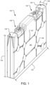
- FIG. 1 is a perspective view of an example phase-change accommodating rigid fluid container (alternatively, a "phase change fluid container” or a “container”) 100.
- the container 100 includes a variety of features discussed in detail herein that protect the container 100 from phase changes of a fluid (not shown) stored therein. As a result, the container 100 may be in direct contact with the fluid without any flexible membrane or bag there between.
- the container 100 includes a body 101 that is depicted as generally a rectangular box, but may be another volume-enclosing shape or combination of shapes with one or more of the features described in detail below. Further, the container 100 may be any size (e.g., 2 liters to 200 liters) and used for storing any fluid (e.g., medical or pharmaceutical fluids). Still further, the container 100 may be made of any suitable material (e.g., various plastics (polyethylene), metals, or composite materials) using any suitable manufacturing process (e.g., molding (rotational molding, injection molding, extrusion molding, blow molding), welding, etc.). Further still, the container 100 is rigid in that it holds a defined shape when not under stress imposed by the fluid stored therein.
- any suitable material e.g., various plastics (polyethylene), metals, or composite materials
- any suitable manufacturing process e.g., molding (rotational molding, injection molding, extrusion molding, blow molding), welding, etc.
- the rigid container 100 may deform to accommodate a phase change of the fluid (e.g., the container may bow outward when the fluid freezes). Further yet, the container 100 may be configured for a single use (i.e., fill and discharge once), multiple uses (i.e., repeated fills and discharges), short-term storage, and/or long term storage of the fluid.
- the container 100 is generally defined as having an exterior length 122, exterior height 124, and exterior width 126 and a relatively constant wall thickness (not shown). In other implementations, the wall thickness may vary such that higher stress areas of the container 100 have thicker walls for more strength and lower stress areas of the container 100 have thinner walls for more flexibility and cost/weight savings.
- the container 100 has length/width and height/width aspect ratios that vary from 4 to 10. The relatively high aspect ratio dimensional characteristics of the container 100 allows the fluid therein to freeze relatively quickly on outside surfaces mostly defined by the width of the container 100. Within the interior of the container 100, the last part of the fluid to freeze pushes upward, displacing some headspace without damaging or significantly deforming the container 100.
- the container 100 is designed with sufficient strength to withstand some stress induced by the fluid freezing (see e.g., stiffening ribs, discussed in detail below) and may allow some flexure to also accommodate the stress induced by the fluid freezing within the container 100.
- the container 100 further includes a pair of input/output assemblies 102, 104 that are used for filling and discharging the container 100 as described in detail below with reference to FIG. 4 .
- the input/output assemblies 102, 104 are also used as vents, which provide fluidic communication with the atmosphere and allow fluid to be added and removed from the container 100 and the fluid within the container 100 to freeze and thaw without building pressure within the container 100.
- the input/output assemblies 102, 104 incorporate filters and/or screens that prevent contaminants from entering the container 100 or leaving the container 100, either via a filling or discharging fluid stream or an entering or exiting venting gas stream.
- the input/output assemblies 102, 104 are recessed into the body 101 (see recesses 216, 218 of FIG. 2 ) to help protect against impact damage during manipulation of the container 100 or manipulation of equipment or other objects in close proximity to the container 100. Recessing the input/output assemblies 102, 104 increases the likelihood that an impact sustained by the container 100 is absorbed by the body 101 rather than the input/output assemblies 102, 104 themselves.
- the container 100 also includes a pair of troughs 136, 138 that are used in conjunction with the input/output assemblies 102, 104, respectively.
- the container 100 may be rotated such that the trough 138 is oriented at the bottom of the container 100 (see e.g., FIG. 11 ).
- Gravity forces the fluid toward the trough 138 and the trough 138 serves to funnel the fluid to a point located at the very bottom of the container 100 where a straw (not shown, see e.g., FIG. 4 ) is utilized by the input/output assembly 104 to withdraw the maximum amount of fluid from the container 100 with a minimum amount of waste fluid that remains unobtainable.
- the remaining unobtainable waste fluid is less than 0.1% of the total volume of the container 100. In other implementations, the remaining unobtainable waste fluid is about than 0.06% of the total volume of the container 100.
- the container 100 also includes an array of manipulation recesses (e.g., recess 106) in the body 101.
- the interior of each of the recesses is fully closed such that the container 100 is sealed from the atmosphere aside from the input/output assemblies 102, 104.
- the container 100 may be physically secured and manipulated via the recesses.
- pins or rods may extend into two or more of the recesses and the container 100 may be moved or manipulated by moving the pins or rods in unison or with reference to one another.
- straps may extend into one or more of the recesses that permit the container 100 to be moved or manipulated by moving the straps in unison or with reference to one another. While eight cylindrical recesses are depicted extending into the container 100, the recesses may be any size, shape, or number appropriate for the intended movement or manipulation of the container 100. Further, the recesses may taper through the width of the container 100 for ease of manufacturing. The recesses may also each include a countersink or counterbore surrounding the individual recesses (see e.g., FIG. 2 ).
- the countersink or counterbore may increase localized stiffness and/or rigidity at the recesses and may also serve to guide the pins, rods, or straps to the recesses when the pins, rods, or straps are interfaced with the container 100, and may serve to recess corresponding pin, rod, or strap fastening hardware within the surrounding body 101.
- the recesses do not extend completely through the container body 101.
- the recesses are utilized by pressing corresponding pins from each side of the container body 101 into a recess to manipulate the recess.
- the recesses that may or may not extend entirely through the container body 101 are collectively referred to herein as lifting points.
- the container 100 also includes stiffening ribs (e.g., rib 107) that provide additional stiffness to the sidewalls of the container 100.
- the stiffening ribs are formed channels in the body 101 of the container 100 that may protrude inward relative to the surrounding body 101 (as shown herein), or protrude outward relative to the surrounding body 101. Further, the stiffening ribs approach the recesses, but stop short of connecting the recesses to preserve the structural integrity of the recesses and avoid introducing any rapid transitions that may lead to reduced thickness of material in some manufacturing processes.
- the stiffening ribs connect the recesses, which may provide additional strength to the recesses when they are used as lifting points. Use of the stiffening ribs to increase strength at the recesses may also increase localized stiffness and/or rigidity at the recesses.
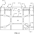
- FIG. 2 is an elevation view of an example phase-change accommodating rigid fluid container 200 in a freeze/thaw (or phase-change) orientation.
- the container 200 includes a variety of features discussed in detail herein that protect the container 200 from phase changes of a fluid 214 existing below fluid line 210. Headspace 212 exists above the fluid line 210. By orienting the container 200 in the freeze/thaw orientation as shown, each of a pair of input/output assemblies 202, 204 are in the headspace 212 and thus not susceptible to damage due to freeze expansion and thaw contraction of the fluid 214.
- the container 200 includes a body 201 that is depicted as generally a rectangular box, but may be another volume-enclosing shape or combination of shapes with one or more of the features described herein.
- the pair of input/output assemblies 202, 204 are used for filling and discharging the container 200 as described in detail below with reference to FIG. 4 .
- the input/output assemblies 202, 204 are also used as vents, which provide fluidic communication with the atmosphere and allow fluid to be added and removed from the container 200 and the fluid 214 within the container 200 to freeze and thaw without building pressure within the container 200.
- the container 200 still further includes input/output recesses 216, 218 that recess the input/output assemblies 202, 204 into the body 201 to help protect against impact damage during manipulation of the container 200 or manipulation of equipment or other objects in close proximity to the container 200. Recessing the input/output assemblies 202, 204 increases the likelihood that an impact sustained by the container 200 is absorbed by the body 201 rather than the input/output assemblies 202, 204 themselves.
- the container 200 also includes a pair of troughs 236, 238 that are used in conjunction with the input/output assemblies 202, 204, respectively.
- the container 200 may be rotated such that the trough 238 is oriented at the bottom of the container 200 (see e.g., FIG. 11 ).
- Gravity forces the fluid toward the trough 238 and the trough 238 serves to funnel the fluid to a point located at the very bottom of the container 200 where a straw (not shown, see e.g., FIG. 4 ) is utilized by the input/output assembly 204 to withdraw the maximum amount of fluid from the container 200 with a minimum amount of waste fluid that remains unobtainable.
- the container 200 also includes an array of manipulation recesses (e.g., recess 206) in the body 201.
- the interior of each of the recesses is fully closed such that the container 200 is sealed from the atmosphere aside from the input/output assemblies 202, 204.
- the container 200 may be physically secured and manipulated via the recesses.
- the recesses may be any size, shape, or number appropriate for the intended movement or manipulation of the container 200.
- the recesses may also each include a countersink or counterbore (e.g., countersink or counterbore 208) surrounding the individual recesses.
- the countersink or counterbore may increase localized stiffness and/or rigidity at the recesses and may also serve to guide manipulation hardware to the recesses when the manipulation hardware is interfaced with the container 200.
- the countersink or counterbore may also serve to recess a portion of the manipulation hardware within the surrounding body 201. In implementations that utilize countersinks at each recess, the countersinks may serve to aid alignment with the manipulation hardware that may be imprecisely directed at the recesses (i.e., a self-centering feature).
- each recess may have a draft angle that narrows the recess toward a center of the container 200.
- recess 206 has a countersink 208. At a base of the countersink 208, the recess 206 has recess diameter 232.
- the recess 206 has a further draft angle that concentrically narrows the recess 206 to recess diameter 234, which is less than recess diameter 232 by virtue of the draft angle.
- the draft angle may vary from 1-10 degrees.
- the recess diameter 234 may exist at a center of the overall width of the container 200, with the draft angle narrowing the recess diameter from recess diameter 232 to recess diameter 234 from each side of the container 200 in a mirror image (only one side of the container 200 is shown in FIG. 2 ).
- the draft angle may extend through the entire width of the container 200 and thus the recess diameters 232, 234 exist at opposing surfaces of the container body 201.
- the draft angle aids in manufacturing the container 200.
- the recesses do not incorporate a draft angle.
- the recesses do not extend completely through the container body 201 and are entirely counterbores or countersinks in the container body 201.
- the container 200 also includes stiffening ribs (e.g., rib 207) that provide additional stiffness to the sidewalls of the container 200.
- the stiffening ribs are formed channels in the body 201 of the container 200 that may protrude inward relative to the surrounding body 201 (as shown herein), or protrude outward relative to the surrounding body 201. Further, the stiffening ribs approach the recesses, but stop short of connecting the recesses to preserve the structural integrity of the recesses and avoid introducing any rapid transitions that may lead to reduced thickness of material in some manufacturing processes. Further, the stiffening ribs may be used to further reinforce the input/output recesses 216, 218 as shown.
- the stiffening ribs connect the recesses, which may provide additional strength to the recesses when they are used as lifting points. Use of the stiffening ribs to increase strength at the recesses may also increase localized stiffness and/or rigidity at the recesses.
- the stiffening ribs include flared ends (e.g., flared end 228) that provide smoother transitions to the surrounding body 201.
- the flared ends may reduce the occurrence of stress concentrations in the body 201 and reduce localized thinning of material that would otherwise occur when manufacturing the container 200 with more abrupt transitions.
- the stiffening ribs do not include flared ends.
- the container 200 is depicted mostly full with the fluid 214 existing below the fluid level 210 and the small headspace 212 existing above the fluid level 210.
- the container 200 is capable of storing any fluid, however, the container 200 is particularly adapted to store fluids under pressure and temperature conditions where a phase change between a solid phase and a liquid phase is possible or expected.
- the fluid 214 may fill any percentage of the container 200 up to a 100% fill state by volume. In some implementations, the fluid 214 is not permitted to fill the container 200 up to the 100% fill state in a liquid phase to provide sufficient room for expansion as the liquid phase fluid turns into a solid phase (i.e., the fluid 214 freezes).
- the fluid 214 may also not be permitted to fill the container 200 to a level that partially or fully occupies the input/output recesses 216, 218 to avoid potentially damaging the input/output assemblies 202, 204 during a phase change.
- the remaining percentage of the container 200 that is not filled with the fluid 214 is referred to as the headspace 212.
- the container 200 may store 90% liquid water or an aqueous solution (i.e., a solution with water as the primary solvent) and 10% atmospheric or other gases. Some portion of the headspace 212 is allowed to adjust during filling and discharging operations as well as during freezing and thawing of the fluid 214 within the container 200.
- FIG. 3 is a cross-sectional elevation view of the example phase-change accommodating rigid fluid container 200 of FIG. 2 (here, container 300) taken at section A-A.
- the container 300 includes a variety of features discussed in detail herein that protect the container 300 from phase changes of a fluid stored therein.
- the container 300 includes a body 301 that is depicted as generally a rectangular box, but may be another volume-enclosing shape or combination of shapes with one or more of the features described herein.
- the container 300 includes an array of recesses 303, 305, 306, 309 in the body 301.
- the recesses are arranged in matched pairs.
- recesses 303, 305 are a matched pair of recesses in opposing sides of the container 300.
- recesses 306, 309 are a matched pair of recesses in opposing sides of the container 300.
- the interior of each of the recesses is fully closed such that the container 300 is sealed from the atmosphere aside from input/output ports (e.g., input/outlet port 320).
- the container 300 may be physically secured and manipulated via the recesses.
- Section A-A illustrates four example cylindrical recesses in the container 300
- the recesses may be any size, shape, or number appropriate for the intended movement or manipulation of the container 300.
- the recesses may also each have a countersink (e.g., countersink 308) surrounding the individual recesses.
- the countersink 308 may be straight or rounded in either a convex (as shown) or concave orientation. In other implementations, counterbores may be included in place of the depicted rounded countersinks.
- the countersinks may increase localized stiffness and/or rigidity at the recesses and may also serve to guide manipulation hardware to the recesses when the manipulation hardware is interfaced with the container 300, and may serve to recess a portion of the manipulation hardware within the surrounding body 301.
- the countersinks may also serve to aid alignment with the manipulation hardware that may be imprecisely directed at the recesses (i.e., a self-centering feature).
- each recess may have a draft angle that narrows the recess toward a center of the container.
- recess 306 has a countersink 308.
- the recess 306 has recess diameter 332.
- the recess 306 has a further draft angle that concentrically narrows the recess 306 to recess diameter 334, which is less than recess diameter 332 by virtue of the draft angle.
- the recess diameter 334 exists at a center of the overall width of the container 300, with the draft angle narrowing the recess diameter from recess diameter 332 to recess diameter 334 from each side of the container 300 in a mirror image, as shown.
- the draft angle may extend through the entire width of the container 300 and thus the recess diameters 332, 334 exist at opposing surfaces of the container body 301.
- the draft angle aids in manufacturing of the container 300.
- the recesses may not extend completely through the container body 301, and thus have a corresponding base structure (e.g., base structure 333).
- the base structure is shared between matched pairs of recesses.
- each recess has its own base structure distinct from the base structure of an opposing recess.
- the recesses extend entirely through the container body 301, thus linking matched pairs of recesses through the container body 301.
- FIG. 4 is a detail perspective view of an example input/output assembly 402 for a phase-change accommodating rigid fluid container 400.
- the container 400 includes a variety of features discussed in detail herein that protect the container 400 from phase changes of a fluid stored therein.
- the container 400 includes a body 401 that may be any volume-enclosing shape or combination of shapes with one or more of the features described herein.
- the input/output assembly 402 is used for filling and discharging the container 400.
- a second similar input/output assembly (not shown) may also be included in the container 400 as shown in FIGs. 1 and 2 .
- the input/output assembly 402 is also used as a vent, which provides fluidic communication with the atmosphere and allows fluid to be added and removed from the container 400 and the fluid within the container 400 to freeze and thaw without building pressure within the container 400 (i.e., pressure equalization between the container 400 and atmospheric pressure).
- the input/output assembly 402 includes an input/output port 420, through which a straw 440 extends to a point in close proximity to a bottom of a trough 436.
- a second similar trough may also be included in the container 400 as shown in FIGs. 1 and 2 .
- the container 400 may be rotated such that the trough 436 is oriented at the bottom of the container 400 (see e.g., FIG. 11 ).
- Gravity forces the fluid toward the trough 436 and the trough 436 serves to funnel the fluid to a point located at the very bottom of the container 400 where the straw 440 is utilized by the input/output assembly 402 to withdraw the maximum amount of fluid from the container 400 with a minimum amount of waste fluid that remains unobtainable.
- the straw 440 extends out of the input/output port 420 and terminates with a barb (not shown, see e.g., barb 552 of FIG. 5 ).
- a cap 442 secures the straw 440 to the container 400 and seals the straw 440 against the input/output port 420.
- the cap 442 may be screwed or pressed on depending on the desired implementation. Further, the cap 442 may be removably attached or permanently affixed to the input/output port 420 and/or the straw 440.
- a tube 444 is attached to the barb and extends away from the input/output port 420.
- the tube 444 is depicted with a y-configuration that splits access to the input/output port 420 into two separate tube sections that each terminate distal to the input/output port 420.
- the tube 444 may be silicone, rubber, or plastic in construction, depending on the intended use of the container 400.
- the tube 444 lacks the depicted y-configuration and merely terminates with a single end distal from the input/output port 420.
- the distal ends of the tube 444 are each capped with a connector (e.g., an aseptic connector 446) that interfaces with equipment intended to withdraw the fluid from the container 400.
- a connector e.g., an aseptic connector 446
- the connectors are merely removable caps on the tube 444 that prevent the fluid from inadvertently leaking from the container 400.
- the connectors may not be airtight so that atmospheric air and/or fluid vapor is permitted to enter and exit the container 400 as the fluid changes phase (and thus volume) within the container 400.
- the container 400 still further includes an input/output recess 416 that recesses the input/output assembly 402 into the body 401 to help protect against impact damage during manipulation of the container 400 or manipulation of equipment or other objects in close proximity to the container 400.
- a second similar input/output recess may also be included in the container 400 as shown in FIGs. 1 and 2 . Recessing the input/output assembly 402 increases the likelihood that an impact sustained by the container 400 is absorbed by the body 401 rather than the input/output assembly 402 itself.
- the container 400 also includes stiffening ribs (e.g., rib 407) that provide additional stiffness to the sidewalls of the container 400.
- the stiffening ribs are formed channels in the body 401 of the container 400 that may protrude inward relative to the surrounding body 401 (as shown herein), or protrude outward relative to the surrounding body 401. Further, the stiffening ribs approach the recesses, but stop short of connecting the recesses. Still further, the stiffening ribs may be used to further reinforce the input/output recess 416 as shown. In other implementations, the stiffening ribs connect the recesses.
- the input/output assembly 402 further includes a retainer bracket 448 that includes clips (e.g., clip 450) that secure the tube 444 and connectors within the input/output recess 416. More specifically, the retainer bracket 448 clips onto stiffening ribs that run on opposing sides of the container 400 and adjacent the input /output recess 416, as shown. In other implementations, the retainer bracket 448 may be otherwise mechanically or adhesively fastened to the body 401 of the container 400. The clips are secured to the retainer bracket 448 and clip onto the tube 444 to hold the tube 444 in place while the input/output assembly 402 is not in use. A user may remove the tube 444 from the clips as needed to utilize the connectors to withdraw fluid from the container 400 or add fluid to the container 400. In various implementations, the retainer bracket 448 and associated clips are of a metal or plastic construction.
- the clips may also be used to secure a sample (e.g., a tailgate sample 441) of the fluid stored within the container 400 for testing and/or overall container 400 content validation purposes.
- a sample e.g., a tailgate sample 441
- the tailgate sample 441 is a closed container separate from the container 400 that stores a sample of the fluid stored within the container 400.
- the tailgate sample 441 may also include a sample port 443 that may be secured to one of the caps that facilitates access to the tailgate sample 441.
- FIG. 5 is a cross-sectional elevation view of the example input/output assembly 402 of FIG. 4 (here, input/output assembly 502) taken at section B-B.
- the input/output assembly 502 may be used to fill, discharge, and/or vent an associated container (see e.g., container 400 of FIG. 4 ), while permitting the container to freeze and thaw without building pressure within the container.
- the input/output assembly 502 includes an input/output port 520, through which a straw 540 extends to a point in close proximity to a bottom of a trough 536.
- the straw 540 turns approximately 90 degrees at the bottom of the trough 536 so that the end of the straw 540 runs generally parallel to the trough 536. This may reduce turbulence within the trough 536 when fluid is added or removed from the container via the straw 540.
- the straw 540 extends out of the input/output port 520 and terminates with a barb 552.
- a cap 542 secures the straw 540 to the container and seals the straw 540 against the input/output port 520.
- a tube 544 is attached to the barb 552 and extends away from the input/output port 520. A distal end of the tube 544 is capped with connector 546 that interfaces with equipment intended to withdraw the fluid from the container.
- the input/output assembly 502 further includes a retainer bracket 548 that includes clips (e.g., clip 550) that secure the tube 544 and connector 546. More specifically, the clips are secured to the retainer bracket 548 and clip onto the tube 544 to hold the tube 544 in place while the input/output assembly 502 is not in use. Some of the clips may also be used to secure a sample (e.g., a tailgate sample 541) of the fluid stored within the container for testing and/or verification purposes.
- a sample e.g., a tailgate sample 541
- FIG. 6 is a perspective view of an example locking mechanism 654 for an input/output assembly (not shown, see e.g., input/output assembly 702 of FIG. 7 ) of a phase-change accommodating rigid fluid container (not shown, see e.g., container 700 of FIG. 7 ).
- the locking mechanism 654 is used in conjunction with a cap (not shown, see e.g., cap 742 of FIG. 7 ) to secure the cap and prevent it from inadvertently loosening. Inadvertent loosening may occur with pressure and temperature changes, fluid phase changes, or mechanical force, for example.
- the locking mechanism 654 may be used to show evidence of unauthorized tampering with a corresponding container.
- the locking mechanism 654 includes two halves 656, 658 in a clamshell arrangement, with pass-throughs 660, 661, 662 acting to selectively connect the halves 656, 658 together.
- a hinge e.g., a live hinge, not shown
- clasps may pass through the pass-throughs 660, 661, 662 to selectively secure the two halves 656, 658 together.
- the clasps extending through the pass-throughs 660, 661, 662 creates a tamper-proof connection that would reveal any unauthorized access to the cap secured by the locking mechanism 654.
- the halves 656, 658 surround and partially enclose the cap.
- protrusions (not shown) from the cap interface with a scalloped or otherwise contoured inner pattern (not shown) of the locking mechanism 654 to prevent the cap from rotating with respect to the locking mechanism 654 when the locking mechanism 654 is installed on the cap.
- the locking mechanism 654 includes a rear flange 668 that prevents the locking mechanism 654 from sliding off the cap.
- the locking mechanism 654 includes mechanical stops 670, 672 that engage with an adjacent fluid container surface (see e.g., fluid container 700 of FIG. 7 ) and prevent rotation of the locking mechanism 654 (and the cap) with respect to the fluid container.
- FIG. 7 is a detail perspective view of an example locking mechanism 754 installed on an input/output assembly 702 for a phase-change accommodating rigid fluid container 700.
- the container 700 includes a variety of features discussed in detail herein that protect the container 700 from phase changes of a fluid stored therein.
- the container 700 includes a body 701 that may be any volume-enclosing shape or combination of shapes with one or more of the features described herein.
- the input/output assembly 702 is used for filling and discharging the container 700.
- a second similar input/output assembly (not shown) may also be included in the container 700 as shown in FIGs. 1 and 2 .
- the input/output assembly 702 may also be used as a vent, which provides fluidic communication with atmosphere and allows fluid to be added and removed from the container 700 and the fluid within the container 700 to freeze and thaw without building pressure within the container 700.
- the input/output assembly 702 includes an input/output port (not shown), through which fluid is added and/or removed from the container 700.
- a pair of tubes 744 extend from the input/output port and are secured to the input/output port via a cap 742.
- the cap 742 screws onto the input/output port to secure the tubes 744 to the container 700 and seal the tubes 744 to the input/output port.
- the cap 742 includes protrusions (not shown) that match and selectively interface with the locking mechanism 754 preventing the cap 742 from rotating with reference to the locking mechanism 754.
- the locking mechanism 754 is clasped around the cap 742 to secure the cap 742 in place.
- the locking mechanism 754 includes a rear flange (not shown, see e.g., rear flange 668 of FIG. 6 ) that prevents the locking mechanism 754 from sliding off the cap 742.
- the locking mechanism 754 includes mechanical stops 770, 772 that engage with the adjacent body 701 and prevent rotation of the locking mechanism 754 and the cap with respect to the fluid container 700.
- the distal ends of the tubes 744 are each capped with a connector (e.g., an aseptic connector 746) that interfaces with equipment intended to withdraw the fluid from the container 700.
- a connector e.g., an aseptic connector 746
- the connectors are merely removable caps on the tubes 744 that prevent the fluid from inadvertently leaking from the container 700.
- the connectors may not be airtight so that atmospheric air and/or fluid vapor is permitted to enter and exit the container 700 as the fluid changes phase (and thus volume) within the container 700.
- the container 700 still further includes an input/output recess 716 that recesses the input/output assembly 702 into the body 701 to help protect against impact damage during manipulation of the container 700 or manipulation of equipment or other objects in close proximity to the container 700.
- a second similar input/output recess may also be included in the container 700 as shown in FIGs. 1 and 2 .
- the container 700 also includes stiffening ribs (e.g., rib 707) that provide additional stiffness to the sidewalls of the container 700.
- the stiffening ribs are formed channels in the body 701 of the container 700 that may protrude inward relative to the surrounding body 701 (as shown herein), or protrude outward relative to the surrounding body 701. Further, the stiffening ribs may be used to further reinforce the input/output recess 716.
- FIG. 8 is a perspective view of an example shroud 874 for a phase-change accommodating rigid fluid container (not shown, see e.g., container 900 of FIG. 9 ).
- the shroud 874 matches a portion of the container to be protected and is configured to slip onto and protect one or more features of the container.
- the shroud 874 may have a similar shape, with an interior profile that closely matches an exterior profile of the container to permit a slip fit between the shroud 874 and the container.
- the shroud 874 has an opening that permits the shroud 874 to be slipped onto the container (e.g., a bottom plan of the depicted shroud 874).
- the shroud 874 includes an array of pass-through apertures (e.g., aperture 806) that correspond in size and location to recesses in the container when the shroud 874 is in place on the container. As a result, the recesses in the container are still accessible whether or not the shroud 874 is in place on the container.
- the shroud 874 includes one or more access panels (e.g., panel 876) that permit access to protected features of the container (e.g., input/output assemblies) without removing the shroud 874.
- the access panels may be open apertures, hinged doors, slip-fit panels, etc.
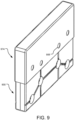
- FIG. 9 is a perspective view of an example shroud 974 utilized on a phase-change accommodating rigid fluid container 900.
- the shroud 974 matches a top portion of the container 900 and is configured to slip over the top of the container 900 and protect one or more features of the container (e.g., input/output assemblies 102, 104 of FIG. 1 ).
- the shroud 974 may have a similar shape, with an interior profile that closely matches an exterior profile of the container 900 to permit a slip fit between the shroud 974 and the container 900.
- the shroud 974 has an opening that permits the shroud 974 to be slipped onto the top of the container 900 (e.g., a bottom plan of the depicted shroud 974).
- the shroud 974 includes an array of pass-through apertures (e.g., aperture 906) that correspond in size and location to recesses in the container 900 when the shroud 974 is in place on the container 900.
- the recesses in the container 900 are still accessible whether or not the shroud 974 is in place on the container 900.
- matching apertures in the shroud 974 and the container 900 may be used to lock the shroud 974 and the container 900 by passing a security cable loop there through.
- FIG. 10 is an elevation view of an example phase-change accommodating rigid fluid container 1000 in a fill orientation.
- the container 1000 includes a variety of features discussed in detail herein that protect the container 1000 from phase changes of a fluid 1014 existing below fluid line 1010. Headspace 1012 exists above the fluid line 1010.
- the container 1000 in the fill orientation is rotated 10 degrees clockwise as compared to the freeze/thaw orientation of container 200 of FIG. 2 .
- Input/output assembly 1002 is utilized as a fluid inlet and input/output assembly 1004 is utilized as a vent.
- the degree of rotation to achieve the fill orientation may vary so long as the venting input/output assembly (here, input/output assembly 1004) remains above the fluid line 1010.
- the fill orientation is rotated counter-clockwise as compared to the freeze/thaw orientation of container 200 of FIG. 2 and the input/output assembly 1002 is utilized as the vent and remains above the fluid line 1010, while the input/output assembly 1004 is utilized as the fluid inlet.
- the fluid 1014 fills the container 1000 via the input/output assembly 1002 as illustrated by arrow 1078. This causes the fluid line 1010 to rise, as illustrated by arrow 1080 and fluid vapor to exit the container 1010 via the input/output assembly 1004, as illustrated by arrow 1082. More generally, as the container 1000 is filled with the fluid 1014 via the input/output assembly 1002, the fluid level 1010 rises and the headspace 1012 shrinks. Headspace gas that the fluid 1014 displaces as it fills the container 1000 is discharged from the container 1000 via the input/output assembly 1004. In some implementations, the fluid 1014 is not allowed to completely fill the container 1000, thus always leaving some headspace 1012 to accommodate freeze expansion within the container 1000.
- FIG. 11 is an elevation view of an example phase-change accommodating rigid fluid container 1100 in a discharge orientation.
- the container 1100 includes a variety of features discussed in detail herein that protect the container 1100 from phase changes of a fluid 1114 existing below fluid line 1110. Headspace 1112 exists above the fluid line 1110.
- the container 1100 in the discharge orientation is rotated 100 degrees clockwise as compared to the freeze/thaw orientation of container 200 of FIG. 2 .
- Input/output assembly 1102 is utilized as a fluid exit and input/output assembly 1104 is utilized as a vent.
- the degree of rotation to achieve the discharge orientation may vary so long as the fluid exit input/output assembly (here, input/output assembly 1102) is oriented near the bottom of the container 1100. Further, a maximum amount of the fluid may be discharged from the container 1100 when the container 1100 is oriented with a fluid exit trough 1136 at or near the bottom of the container 1100, as shown.
- the discharge orientation is rotated counter-clockwise as compared to the freeze/thaw orientation of container 200 of FIG. 2 and the input/output assembly 1102 is utilized as the vent, while the input/output assembly 1104 is utilized as the fluid exit.
- the fluid 1114 exits the container 1100 via the input/output assembly 1102 as illustrated by arrow 1178. This causes the fluid line 1110 to drop, as illustrated by arrow 1180, and atmospheric air or other gases to enter the container 1110 via the input/output assembly 1104, as illustrated by arrow 1182. More generally, as the fluid 1114 is drained from the container 1100 via the input/output assembly 1102, the fluid level 1110 drops and the headspace 1112 shrinks. Atmospheric air or other gases enter the container 1100 via the input/output assembly 1104 replace the fluid 1114 as it is discharged from the container 1100.
- FIG. 12 is an elevation view of another example phase-change accommodating rigid fluid container 1200 in a freeze/thaw (or phase-change) orientation.
- the container 1200 includes a body 1201 that is depicted as generally a rectangular box, but may be another volume-enclosing shape or combination of shapes with one or more of the features described herein.
- the container 1200 includes input/output recesses 1216, 1218 that recess the input/output assemblies (not shown) into the body 1201 to help protect against impact damage during manipulation of the container 1200 or manipulation of equipment or other objects in close proximity to the container 1200.
- the container 1200 also includes an array of manipulation recesses (e.g., recess 1206) in the body 1201. The interior of each of the recesses is fully closed such that the container 1200 is sealed from the atmosphere aside from the input/output assemblies.
- the container 1200 may be physically secured and manipulated via the recesses.
- the recesses may be any size, shape, or number appropriate for the intended movement or manipulation of the container 1200.
- the recesses may also each include a countersink or counterbore (e.g., counterbore 1208) surrounding the individual recesses.
- the countersink or counterbore may increase localized stiffness and/or rigidity at the recesses and may also serve to guide manipulation hardware to the recesses when the manipulation hardware is interfaced with the container 1200.
- the countersink or counterbore may also serve to recess a portion of the manipulation hardware within the surrounding body 1201. In implementations that utilize countersinks at each recess, the countersinks may serve to aid alignment with the manipulation hardware that may be imprecisely directed at the recesses (i.e., a self-centering feature).
- each recess may have one or more draft angles that narrow the recess toward a center of the container 1200.
- recess 1206 has a counterbore 1208. At a base of the counterbore 1208, the recess 1206 has recess diameter 1232.
- the recess 1206 has a further draft angle that concentrically narrows the recess 1206 to recess diameter 1234, which is less than recess diameter 1232 by virtue of the draft angle.
- the draft angle may vary from 1-10 degrees.
- the recess diameter 1234 may exist at a center of the overall width of the container 1200, with the draft angle narrowing the recess diameter from recess diameter 1232 to recess diameter 1234 from each side of the container 1200 in a mirror image (only one side of the container 1200 is shown in FIG. 12 ).
- the draft angle may extend through the entire width of the container 1200 and thus the recess diameters 1232, 1234 exist at opposing surfaces of the container body 1201.
- the draft angle aids in manufacturing the container 1200.
- the recesses do not incorporate a draft angle.
- the recesses do not extend completely through the container body 1201 and are entirely counterbores or countersinks in the container body 1201.
- the container 1200 also includes stiffening ribs (e.g., rib 1207) that provide additional stiffness to the sidewalls of the container 1200.
- the stiffening ribs are formed channels in the body 1201 of the container 1200 that may protrude inward relative to the surrounding body 1201 (as shown herein), or protrude outward relative to the surrounding body 1201.
- the stiffening ribs connect the recesses, which may provide additional strength to the recesses when they are used as lifting points. Use of the stiffening ribs to increase strength at the recesses may also increase localized stiffness and/or rigidity at the recesses. Further, the stiffening ribs may be used to further reinforce the input/output recesses 1216, 1218 as shown. In other implementations, the stiffening ribs approach the recesses, but stop short of connecting the recesses to preserve the structural integrity of the recesses and avoid introducing any rapid transitions that may lead to reduced thickness of material in some manufacturing processes.
- the stiffening ribs include flared ends (not shown) that provide smoother transitions to the surrounding body 1201 and connected recesses.
- the flared ends may reduce the occurrence of stress concentrations in the body 1201 and reduce localized thinning of material that would otherwise occur when manufacturing the container 1200 with more abrupt transitions.
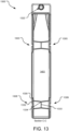
- FIG. 13 is a cross-sectional elevation view of the example phase-change accommodating rigid fluid container 1200 of FIG. 12 (here, container 1300) taken at section C-C.
- the container 1300 includes a variety of features discussed in detail herein that protect the container 1300 from phase changes of a fluid stored therein.
- the container 1300 includes a body 1301 that is depicted as generally a rectangular box, but may be another volume-enclosing shape or combination of shapes with one or more of the features described herein.
- the container 1300 includes an array of recesses 1303, 1305, 1306, 1309 in the body 1301.
- the recesses are arranged in matched pairs.
- recesses 1303, 1305 are a matched pair of recesses in opposing sides of the container 1300.
- recesses 1306, 1309 are a matched pair of recesses in opposing sides of the container 1300.
- the interior of each of the recesses is fully closed such that the container 1300 is sealed from the atmosphere aside from input/output ports (e.g., input/outlet port 1320).
- the container 1300 may be physically secured and manipulated via the recesses.
- Section C-C illustrates four example cylindrical recesses in the container 1300
- the recesses may be any size, shape, or number appropriate for the intended movement or manipulation of the container 1300.
- the recesses may also each have a counterbore (e.g., counterbore 1308) surrounding the individual recesses.
- countersinks may be included in place of the depicted counterbores.
- the counterbores may increase localized stiffness and/or rigidity at the recesses and may also serve to guide manipulation hardware to the recesses when the manipulation hardware is interfaced with the container 1300, and may serve to recess a portion of the manipulation hardware within the surrounding body 1301.
- the counterbores may also serve to aid alignment with the manipulation hardware that may be imprecisely directed at the recesses (i.e., a self-centering feature).
- each recess may have a draft angle that narrows the recess toward a center of the container.
- recess 1306 has a counterbore 1308.
- the recess 1306 has recess diameter 1332.
- the recess 1306 has a further draft angle that concentrically narrows the recess 1306 to recess diameter 1334, which is less than recess diameter 1332 by virtue of the draft angle.
- the recess diameter 1334 exists at a center of the overall width of the container 1300, with the draft angle narrowing the recess diameter from recess diameter 1332 to recess diameter 1334 from each side of the container 1300 in a mirror image, as shown.
- the draft angle may extend through the entire width of the container 1300 and thus the recess diameters 1332, 1334 exist at opposing surfaces of the container body 1301.
- the draft angle aids in manufacturing of the container 1300.
- the recesses may not extend completely through the container body 1301, and thus have a corresponding base structure (e.g., base structure 1333).
- the base structure is shared between matched pairs of recesses.
- each recess has its own base structure distinct from the base structure of an opposing recess.
- the recesses extend entirely through the container body 1301, thus linking matched pairs of recesses through the container body 1301.
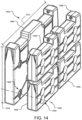
- FIG. 14 is a perspective view of a stackable array 1400 of phase-change accommodating rigid fluid containers of varying size.
- a larger container 1480 e.g., a 100 liter container
- the larger container 1480 has an exterior length 1422 and an exterior height 1424 that defines its profile dimension.
- the smaller containers 1482, 1484, 1486, 1488 each have smaller profile dimensions, but in combination have a profile dimension that substantially matches the profile dimension of the larger container 1480.
- multiple sizes of containers are able to be stacked adjacent to one another in similar space constraints.
- matched pairs of recesses in the large container align with matched pairs of recesses in the smaller containers (e.g., matched pair 1494), as illustrated by dashed line 1492.
- manipulation hardware may engage the large container and smaller containers via the aligned matched pairs of recesses to physically manipulate the array of containers as a unit.
- FIG. 15 illustrates example operations 1500 for using a phase-change accommodating rigid fluid container.
- a filling operation 1505 fills the container with a fluid via a pair of input/output assemblies.
- the container is oriented in a fill orientation, which places one of the input/output assemblies in a headspace of the container above another of the input/output assemblies. This allows the input/output assembly in the headspace to serve as a vent to atmosphere, thereby maintaining pressure equalization within the container to atmospheric pressure. More specifically, the vent provides an exit to atmosphere for gases that are displaced by the fluid introduced into the container.
- the other input/output assembly is used to introduce the fluid into the container.
- the container is filled at any desired fill state that maintains a minimum headspace volume to accommodate expected freeze expansion and thaw contraction.
- a locking operation 1510 locks a cap of one or both of the input/output assemblies in place.
- the locking operation 1510 may utilize locking mechanisms that partially enclose the caps and prevents rotation of the caps with respect to the locking mechanisms and rotation of the locking mechanisms with respect to the container.
- the locking mechanisms prevent the caps from inadvertently unscrewing from the input/output assemblies.
- the locking mechanisms prevent unauthorized tampering or alerts to unauthorized tampering with the input/output assemblies.
- the locking operation 710 may be omitted where inadvertent or unauthorized unscrewing of the caps from the input/output assemblies is not of concern.
- a freezing operation 1515 freezes the fluid stored within the container.
- the container is placed in a phase-change orientation during the freezing operation, which orients both of the input/output assemblies in a headspace of the container.
- any phase-change of the fluid does not impact the input/output assemblies, which may be susceptible to damage from the phase change.
- the aspect ratio (height/width and/or length/width) and other disclosed features of the container prevent the freezing operation 1515 from damaging the container.
- An interfacing operation 1520 interfaces two or more matched pairs of recesses in a body of the container with manipulation hardware.
- the container includes the matched recesses to enable easy physical manipulation of the container.
- the matched pairs of recesses are oriented on opposing sides of the container and the manipulation hardware either extends through the recesses (in the event the pairs of recesses connect through the container) or pinches the container at the recesses to attach to the container.
- a suspending operation 1525 suspends the container via the recesses.
- the manipulation hardware lifts the container via the recesses and the container is structurally configured such that it may be fully supported via the recesses.
- a moving operation 1530 moves the container to a new location and/or orientation.
- the manipulation hardware may be moved in concert to physically relocate the container. Further, the manipulation hardware may be moved with respect to itself to physically re-orient the container (e.g., to move from fill, phase-change, and discharge orientations).
- a thawing operation 1535 thaws the frozen fluid stored within the container.
- the fluid within the container is not entirely frozen in operation 1515 and/or entirely thawed in operation 1535.
- the container is merely able to withstand full phase changes, should they occur.
- freezing operation 1515 and thawing operation 1535 may be repeated during performance of the operations 1500, for example, during transit of the container.
- An unlocking operation 1540 unlocks the caps of the input/output assemblies.
- the unlocking operation 1540 is achieved by removing the locking mechanisms from the caps of the input/output assemblies.
- the unlocking operation 1540 may be omitted when the locking operation 1510 is omitted.
- a discharging operation 1545 discharges the fluid from the container via the input/output assemblies.
- the container is oriented in a discharge orientation, which places a straw of one of the input/output assemblies at a low-point of the container.
- the other of the input/output assemblies is utilized as a vent, permitting pressure equalization gases (atmospheric air or other gases) into the container as the fluid is drained from the container, thereby maintaining pressure equalization within the container to atmospheric pressure. More specifically, the vent provides an entrance for gases to displace the fluid that is discharged from the container.
Landscapes
- Engineering & Computer Science (AREA)
- Mechanical Engineering (AREA)
- Health & Medical Sciences (AREA)
- Hematology (AREA)
- Pharmacology & Pharmacy (AREA)
- Life Sciences & Earth Sciences (AREA)
- Animal Behavior & Ethology (AREA)
- General Health & Medical Sciences (AREA)
- Public Health (AREA)
- Veterinary Medicine (AREA)
- Packages (AREA)
- Details Of Rigid Or Semi-Rigid Containers (AREA)
Description
- The invention relates generally to rigid fluid containers and methods of using the same.
- Conventional fluid containers, including both rigid and compliant containers, come in a variety of shapes and sizes with a variety of features, some of which accommodate a fluid phase change within the container. For example, some fluids (e.g., medical fluids) are stored and transported in compliant bags, which offer flexibility in the event the fluid freezes, but poor protection from physical puncture of the bag, which may contaminate the fluid. Other fluids are stored and transported in rigid containers, which may provide better protection from physical puncture, but may fracture due to expansion and contraction of the fluid as it freezes and thaws. Still other fluids are stored in a combination container (e.g., a flexible bag inside a rigid container), which may offer some of the benefits of each type of container, but with the added expense of redundant storage containers for a defined volume of fluid.
- Each of the conventional rigid, compliant, and combined fluid containers lack a combination of features that comprehensively protects the container from fluid phase changes and external threats to the container while permitting easy physical manipulation of the container, including freeze/thaw resistance, puncture resistance, and input/output assemblies that are both protected and easy to use, for example.
-
GB2473256A - Implementations described and claimed herein address the foregoing problems by providing a fluid container comprising: two or more matched pairs of recesses in a body of the container, each recess in a matched pair oriented on opposing sides of the container, the recesses configured to interface with hardware to physically manipulate the container; and two or more stiffening ribs, each stiffening rib extending between two of the recesses in the body of the container and two input/output assemblies recessed into the body of the container, each configured to act as an input for fluid into the container, an output of fluid from the container, and a vent for pressure equalization within the container to atmospheric pressure.
- Implementations described and claimed herein address the foregoing problems by further providing a method of using a fluid container comprising: interfacing each of two or more matched pairs of recesses in a body of the container with manipulation hardware, each recess in a matched pair oriented on opposing sides of the container; suspending the container from the recesses, wherein each of two or more stiffening ribs extend between two of the recesses in the body of the container, and filling the container with a quantity of fluid using one of two or more input/output assemblies while the container is oriented at a fill orientation and while venting the container to atmosphere for pressure equalization using the other of the input/output assemblies, the input/output assemblies recessed into the body of the container and each being configured to act as an input for fluid into the container, an output of fluid from the container, and a vent for pressure equalization within the container to atmospheric pressure.
- Other implementations are also described and recited herein.
-
-
FIG. 1 is a perspective view of an example phase-change accommodating rigid fluid container. -
FIG. 2 is an elevation view of an example phase-change accommodating rigid fluid container. -
FIG. 3 is a cross-sectional elevation view of the example phase-change accommodating rigid fluid container ofFIG. 2 taken at section A-A. -
FIG. 4 is a detail perspective view of an example input/output assembly for a phase-change accommodating rigid fluid container. -
FIG. 5 is a cross-sectional elevation view of the example input/output assembly ofFIG. 4 taken at section B-B. -
FIG. 6 is a perspective view of an example locking mechanism for an input/output assembly of a phase-change accommodating rigid fluid container. -
FIG. 7 is a detail perspective view of an example locking mechanism installed on an input/output assembly for a phase-change accommodating rigid fluid container. -
FIG. 8 is a perspective view of an example shroud for a phase-change accommodating rigid fluid container. -
FIG. 9 is a perspective view of an example shroud utilized on a phase-change accommodating rigid fluid container. -
FIG. 10 is an elevation view of an example phase-change accommodating rigid fluid container in a fill orientation. -
FIG. 11 is an elevation view of an example phase-change accommodating rigid fluid container in a discharge orientation. -
FIG. 12 is an elevation view of another example phase-change accommodating rigid fluid container. -
FIG. 13 is a cross-sectional elevation view of the example phase-change accommodating rigid fluid container ofFIG. 12 taken at section C-C. -
FIG. 14 is a perspective view of a stackable array of phase-change accommodating rigid fluid containers of varying size. -
FIG. 15 illustrates example operations for using a phase-change accommodating rigid fluid container. -
FIG. 1 is a perspective view of an example phase-change accommodating rigid fluid container (alternatively, a "phase change fluid container" or a "container") 100. Thecontainer 100 includes a variety of features discussed in detail herein that protect thecontainer 100 from phase changes of a fluid (not shown) stored therein. As a result, thecontainer 100 may be in direct contact with the fluid without any flexible membrane or bag there between. - The
container 100 includes abody 101 that is depicted as generally a rectangular box, but may be another volume-enclosing shape or combination of shapes with one or more of the features described in detail below. Further, thecontainer 100 may be any size (e.g., 2 liters to 200 liters) and used for storing any fluid (e.g., medical or pharmaceutical fluids). Still further, thecontainer 100 may be made of any suitable material (e.g., various plastics (polyethylene), metals, or composite materials) using any suitable manufacturing process (e.g., molding (rotational molding, injection molding, extrusion molding, blow molding), welding, etc.). Further still, thecontainer 100 is rigid in that it holds a defined shape when not under stress imposed by the fluid stored therein. Therigid container 100 may deform to accommodate a phase change of the fluid (e.g., the container may bow outward when the fluid freezes). Further yet, thecontainer 100 may be configured for a single use (i.e., fill and discharge once), multiple uses (i.e., repeated fills and discharges), short-term storage, and/or long term storage of the fluid. - The
container 100 is generally defined as having anexterior length 122,exterior height 124, andexterior width 126 and a relatively constant wall thickness (not shown). In other implementations, the wall thickness may vary such that higher stress areas of thecontainer 100 have thicker walls for more strength and lower stress areas of thecontainer 100 have thinner walls for more flexibility and cost/weight savings. In order to achieve the desired freeze/thaw performance, thecontainer 100 has length/width and height/width aspect ratios that vary from 4 to 10. The relatively high aspect ratio dimensional characteristics of thecontainer 100 allows the fluid therein to freeze relatively quickly on outside surfaces mostly defined by the width of thecontainer 100. Within the interior of thecontainer 100, the last part of the fluid to freeze pushes upward, displacing some headspace without damaging or significantly deforming thecontainer 100. In some implementations, thecontainer 100 is designed with sufficient strength to withstand some stress induced by the fluid freezing (see e.g., stiffening ribs, discussed in detail below) and may allow some flexure to also accommodate the stress induced by the fluid freezing within thecontainer 100. - The
container 100 further includes a pair of input/output assemblies container 100 as described in detail below with reference toFIG. 4 . The input/output assemblies container 100 and the fluid within thecontainer 100 to freeze and thaw without building pressure within thecontainer 100. In some implementations, the input/output assemblies container 100 or leaving thecontainer 100, either via a filling or discharging fluid stream or an entering or exiting venting gas stream. - Further, the input/
output assemblies recesses FIG. 2 ) to help protect against impact damage during manipulation of thecontainer 100 or manipulation of equipment or other objects in close proximity to thecontainer 100. Recessing the input/output assemblies container 100 is absorbed by thebody 101 rather than the input/output assemblies - The
container 100 also includes a pair oftroughs output assemblies output assembly 104 is used to drain the fluid from thecontainer 100, thecontainer 100 may be rotated such that thetrough 138 is oriented at the bottom of the container 100 (see e.g.,FIG. 11 ). Gravity forces the fluid toward thetrough 138 and thetrough 138 serves to funnel the fluid to a point located at the very bottom of thecontainer 100 where a straw (not shown, see e.g.,FIG. 4 ) is utilized by the input/output assembly 104 to withdraw the maximum amount of fluid from thecontainer 100 with a minimum amount of waste fluid that remains unobtainable. In various implementations, the remaining unobtainable waste fluid is less than 0.1% of the total volume of thecontainer 100. In other implementations, the remaining unobtainable waste fluid is about than 0.06% of the total volume of thecontainer 100. - The
container 100 also includes an array of manipulation recesses (e.g., recess 106) in thebody 101. The interior of each of the recesses is fully closed such that thecontainer 100 is sealed from the atmosphere aside from the input/output assemblies container 100 may be physically secured and manipulated via the recesses. For example, pins or rods (not shown) may extend into two or more of the recesses and thecontainer 100 may be moved or manipulated by moving the pins or rods in unison or with reference to one another. - In another example, straps (not shown) may extend into one or more of the recesses that permit the
container 100 to be moved or manipulated by moving the straps in unison or with reference to one another. While eight cylindrical recesses are depicted extending into thecontainer 100, the recesses may be any size, shape, or number appropriate for the intended movement or manipulation of thecontainer 100. Further, the recesses may taper through the width of thecontainer 100 for ease of manufacturing. The recesses may also each include a countersink or counterbore surrounding the individual recesses (see e.g.,FIG. 2 ). The countersink or counterbore may increase localized stiffness and/or rigidity at the recesses and may also serve to guide the pins, rods, or straps to the recesses when the pins, rods, or straps are interfaced with thecontainer 100, and may serve to recess corresponding pin, rod, or strap fastening hardware within the surroundingbody 101. - In some implementations, the recesses do not extend completely through the
container body 101. As a result, the recesses are utilized by pressing corresponding pins from each side of thecontainer body 101 into a recess to manipulate the recess. The recesses that may or may not extend entirely through thecontainer body 101 are collectively referred to herein as lifting points. - The
container 100 also includes stiffening ribs (e.g., rib 107) that provide additional stiffness to the sidewalls of thecontainer 100. The stiffening ribs are formed channels in thebody 101 of thecontainer 100 that may protrude inward relative to the surrounding body 101 (as shown herein), or protrude outward relative to the surroundingbody 101. Further, the stiffening ribs approach the recesses, but stop short of connecting the recesses to preserve the structural integrity of the recesses and avoid introducing any rapid transitions that may lead to reduced thickness of material in some manufacturing processes. In other implementations, the stiffening ribs connect the recesses, which may provide additional strength to the recesses when they are used as lifting points. Use of the stiffening ribs to increase strength at the recesses may also increase localized stiffness and/or rigidity at the recesses. -
FIG. 2 is an elevation view of an example phase-change accommodating rigidfluid container 200 in a freeze/thaw (or phase-change) orientation. Thecontainer 200 includes a variety of features discussed in detail herein that protect thecontainer 200 from phase changes of a fluid 214 existing belowfluid line 210.Headspace 212 exists above thefluid line 210. By orienting thecontainer 200 in the freeze/thaw orientation as shown, each of a pair of input/output assemblies headspace 212 and thus not susceptible to damage due to freeze expansion and thaw contraction of thefluid 214. Thecontainer 200 includes abody 201 that is depicted as generally a rectangular box, but may be another volume-enclosing shape or combination of shapes with one or more of the features described herein. - The pair of input/
output assemblies container 200 as described in detail below with reference toFIG. 4 . The input/output assemblies container 200 and the fluid 214 within thecontainer 200 to freeze and thaw without building pressure within thecontainer 200. - The
container 200 still further includes input/output recesses output assemblies body 201 to help protect against impact damage during manipulation of thecontainer 200 or manipulation of equipment or other objects in close proximity to thecontainer 200. Recessing the input/output assemblies container 200 is absorbed by thebody 201 rather than the input/output assemblies - The
container 200 also includes a pair oftroughs output assemblies output assembly 204 is used to drain the fluid from thecontainer 200, thecontainer 200 may be rotated such that thetrough 238 is oriented at the bottom of the container 200 (see e.g.,FIG. 11 ). Gravity forces the fluid toward thetrough 238 and thetrough 238 serves to funnel the fluid to a point located at the very bottom of thecontainer 200 where a straw (not shown, see e.g.,FIG. 4 ) is utilized by the input/output assembly 204 to withdraw the maximum amount of fluid from thecontainer 200 with a minimum amount of waste fluid that remains unobtainable. - The
container 200 also includes an array of manipulation recesses (e.g., recess 206) in thebody 201. The interior of each of the recesses is fully closed such that thecontainer 200 is sealed from the atmosphere aside from the input/output assemblies container 200 may be physically secured and manipulated via the recesses. - While eight cylindrical recesses are depicted in the
container 200, the recesses may be any size, shape, or number appropriate for the intended movement or manipulation of thecontainer 200. The recesses may also each include a countersink or counterbore (e.g., countersink or counterbore 208) surrounding the individual recesses. The countersink or counterbore may increase localized stiffness and/or rigidity at the recesses and may also serve to guide manipulation hardware to the recesses when the manipulation hardware is interfaced with thecontainer 200. The countersink or counterbore may also serve to recess a portion of the manipulation hardware within the surroundingbody 201. In implementations that utilize countersinks at each recess, the countersinks may serve to aid alignment with the manipulation hardware that may be imprecisely directed at the recesses (i.e., a self-centering feature). - Further, each recess may have a draft angle that narrows the recess toward a center of the
container 200. For example,recess 206 has acountersink 208. At a base of thecountersink 208, therecess 206 hasrecess diameter 232. Therecess 206 has a further draft angle that concentrically narrows therecess 206 to recessdiameter 234, which is less thanrecess diameter 232 by virtue of the draft angle. In various implementations, the draft angle may vary from 1-10 degrees. In addition, therecess diameter 234 may exist at a center of the overall width of thecontainer 200, with the draft angle narrowing the recess diameter fromrecess diameter 232 to recessdiameter 234 from each side of thecontainer 200 in a mirror image (only one side of thecontainer 200 is shown inFIG. 2 ). In other implementations, the draft angle may extend through the entire width of thecontainer 200 and thus therecess diameters container body 201. In various implementations, the draft angle aids in manufacturing thecontainer 200. In other implementations, the recesses do not incorporate a draft angle. In addition, in some implementations, the recesses do not extend completely through thecontainer body 201 and are entirely counterbores or countersinks in thecontainer body 201. - The
container 200 also includes stiffening ribs (e.g., rib 207) that provide additional stiffness to the sidewalls of thecontainer 200. The stiffening ribs are formed channels in thebody 201 of thecontainer 200 that may protrude inward relative to the surrounding body 201 (as shown herein), or protrude outward relative to the surroundingbody 201. Further, the stiffening ribs approach the recesses, but stop short of connecting the recesses to preserve the structural integrity of the recesses and avoid introducing any rapid transitions that may lead to reduced thickness of material in some manufacturing processes. Further, the stiffening ribs may be used to further reinforce the input/output recesses - In some implementations, the stiffening ribs include flared ends (e.g., flared end 228) that provide smoother transitions to the surrounding
body 201. As a result, the flared ends may reduce the occurrence of stress concentrations in thebody 201 and reduce localized thinning of material that would otherwise occur when manufacturing thecontainer 200 with more abrupt transitions. In other implementations, the stiffening ribs do not include flared ends. - The
container 200 is depicted mostly full with the fluid 214 existing below thefluid level 210 and thesmall headspace 212 existing above thefluid level 210. Thecontainer 200 is capable of storing any fluid, however, thecontainer 200 is particularly adapted to store fluids under pressure and temperature conditions where a phase change between a solid phase and a liquid phase is possible or expected. The fluid 214 may fill any percentage of thecontainer 200 up to a 100% fill state by volume. In some implementations, the fluid 214 is not permitted to fill thecontainer 200 up to the 100% fill state in a liquid phase to provide sufficient room for expansion as the liquid phase fluid turns into a solid phase (i.e., the fluid 214 freezes). The fluid 214 may also not be permitted to fill thecontainer 200 to a level that partially or fully occupies the input/output recesses output assemblies - The remaining percentage of the
container 200 that is not filled with the fluid 214 is referred to as theheadspace 212. For example, thecontainer 200 may store 90% liquid water or an aqueous solution (i.e., a solution with water as the primary solvent) and 10% atmospheric or other gases. Some portion of theheadspace 212 is allowed to adjust during filling and discharging operations as well as during freezing and thawing of the fluid 214 within thecontainer 200. -
FIG. 3 is a cross-sectional elevation view of the example phase-change accommodating rigidfluid container 200 ofFIG. 2 (here, container 300) taken at section A-A. Thecontainer 300 includes a variety of features discussed in detail herein that protect thecontainer 300 from phase changes of a fluid stored therein. Thecontainer 300 includes abody 301 that is depicted as generally a rectangular box, but may be another volume-enclosing shape or combination of shapes with one or more of the features described herein. - The
container 300 includes an array ofrecesses body 301. In various implementations, the recesses are arranged in matched pairs. For example, recesses 303, 305 are a matched pair of recesses in opposing sides of thecontainer 300. Similarly, recesses 306, 309 are a matched pair of recesses in opposing sides of thecontainer 300. The interior of each of the recesses is fully closed such that thecontainer 300 is sealed from the atmosphere aside from input/output ports (e.g., input/outlet port 320). Thecontainer 300 may be physically secured and manipulated via the recesses. - While Section A-A illustrates four example cylindrical recesses in the
container 300, the recesses may be any size, shape, or number appropriate for the intended movement or manipulation of thecontainer 300. The recesses may also each have a countersink (e.g., countersink 308) surrounding the individual recesses. Thecountersink 308 may be straight or rounded in either a convex (as shown) or concave orientation. In other implementations, counterbores may be included in place of the depicted rounded countersinks. - The countersinks may increase localized stiffness and/or rigidity at the recesses and may also serve to guide manipulation hardware to the recesses when the manipulation hardware is interfaced with the
container 300, and may serve to recess a portion of the manipulation hardware within the surroundingbody 301. The countersinks may also serve to aid alignment with the manipulation hardware that may be imprecisely directed at the recesses (i.e., a self-centering feature). - Further, each recess may have a draft angle that narrows the recess toward a center of the container. For example,
recess 306 has acountersink 308. At a base of thecountersink 308, therecess 306 hasrecess diameter 332. Therecess 306 has a further draft angle that concentrically narrows therecess 306 to recessdiameter 334, which is less thanrecess diameter 332 by virtue of the draft angle. Therecess diameter 334 exists at a center of the overall width of thecontainer 300, with the draft angle narrowing the recess diameter fromrecess diameter 332 to recessdiameter 334 from each side of thecontainer 300 in a mirror image, as shown. In other implementations, the draft angle may extend through the entire width of thecontainer 300 and thus therecess diameters container body 301. In various implementations, the draft angle aids in manufacturing of thecontainer 300. - The recesses may not extend completely through the
container body 301, and thus have a corresponding base structure (e.g., base structure 333). In some implementations, the base structure is shared between matched pairs of recesses. In other implementations, each recess has its own base structure distinct from the base structure of an opposing recess. In still other implementations, the recesses extend entirely through thecontainer body 301, thus linking matched pairs of recesses through thecontainer body 301. -
FIG. 4 is a detail perspective view of an example input/output assembly 402 for a phase-change accommodating rigidfluid container 400. Thecontainer 400 includes a variety of features discussed in detail herein that protect thecontainer 400 from phase changes of a fluid stored therein. Thecontainer 400 includes abody 401 that may be any volume-enclosing shape or combination of shapes with one or more of the features described herein. - The input/
output assembly 402 is used for filling and discharging thecontainer 400. A second similar input/output assembly (not shown) may also be included in thecontainer 400 as shown inFIGs. 1 and2 . The input/output assembly 402 is also used as a vent, which provides fluidic communication with the atmosphere and allows fluid to be added and removed from thecontainer 400 and the fluid within thecontainer 400 to freeze and thaw without building pressure within the container 400 (i.e., pressure equalization between thecontainer 400 and atmospheric pressure). - The input/
output assembly 402 includes an input/output port 420, through which astraw 440 extends to a point in close proximity to a bottom of atrough 436. A second similar trough (not shown) may also be included in thecontainer 400 as shown inFIGs. 1 and2 . For example, when the input/output assembly 402 is used to drain the fluid from thecontainer 400, thecontainer 400 may be rotated such that thetrough 436 is oriented at the bottom of the container 400 (see e.g.,FIG. 11 ). Gravity forces the fluid toward thetrough 436 and thetrough 436 serves to funnel the fluid to a point located at the very bottom of thecontainer 400 where thestraw 440 is utilized by the input/output assembly 402 to withdraw the maximum amount of fluid from thecontainer 400 with a minimum amount of waste fluid that remains unobtainable. - The
straw 440 extends out of the input/output port 420 and terminates with a barb (not shown, see e.g.,barb 552 ofFIG. 5 ). Acap 442 secures thestraw 440 to thecontainer 400 and seals thestraw 440 against the input/output port 420. Thecap 442 may be screwed or pressed on depending on the desired implementation. Further, thecap 442 may be removably attached or permanently affixed to the input/output port 420 and/or thestraw 440. - A
tube 444 is attached to the barb and extends away from the input/output port 420. Thetube 444 is depicted with a y-configuration that splits access to the input/output port 420 into two separate tube sections that each terminate distal to the input/output port 420. In various implementations, thetube 444 may be silicone, rubber, or plastic in construction, depending on the intended use of thecontainer 400. In other implementations, thetube 444 lacks the depicted y-configuration and merely terminates with a single end distal from the input/output port 420. - The distal ends of the
tube 444 are each capped with a connector (e.g., an aseptic connector 446) that interfaces with equipment intended to withdraw the fluid from thecontainer 400. In some implementations, the connectors are merely removable caps on thetube 444 that prevent the fluid from inadvertently leaking from thecontainer 400. Still further, the connectors may not be airtight so that atmospheric air and/or fluid vapor is permitted to enter and exit thecontainer 400 as the fluid changes phase (and thus volume) within thecontainer 400. - The
container 400 still further includes an input/output recess 416 that recesses the input/output assembly 402 into thebody 401 to help protect against impact damage during manipulation of thecontainer 400 or manipulation of equipment or other objects in close proximity to thecontainer 400. A second similar input/output recess (not shown) may also be included in thecontainer 400 as shown inFIGs. 1 and2 . Recessing the input/output assembly 402 increases the likelihood that an impact sustained by thecontainer 400 is absorbed by thebody 401 rather than the input/output assembly 402 itself. - The
container 400 also includes stiffening ribs (e.g., rib 407) that provide additional stiffness to the sidewalls of thecontainer 400. The stiffening ribs are formed channels in thebody 401 of thecontainer 400 that may protrude inward relative to the surrounding body 401 (as shown herein), or protrude outward relative to the surroundingbody 401. Further, the stiffening ribs approach the recesses, but stop short of connecting the recesses. Still further, the stiffening ribs may be used to further reinforce the input/output recess 416 as shown. In other implementations, the stiffening ribs connect the recesses. - The input/
output assembly 402 further includes aretainer bracket 448 that includes clips (e.g., clip 450) that secure thetube 444 and connectors within the input/output recess 416. More specifically, theretainer bracket 448 clips onto stiffening ribs that run on opposing sides of thecontainer 400 and adjacent the input /output recess 416, as shown. In other implementations, theretainer bracket 448 may be otherwise mechanically or adhesively fastened to thebody 401 of thecontainer 400. The clips are secured to theretainer bracket 448 and clip onto thetube 444 to hold thetube 444 in place while the input/output assembly 402 is not in use. A user may remove thetube 444 from the clips as needed to utilize the connectors to withdraw fluid from thecontainer 400 or add fluid to thecontainer 400. In various implementations, theretainer bracket 448 and associated clips are of a metal or plastic construction. - Some of the clips may also be used to secure a sample (e.g., a tailgate sample 441) of the fluid stored within the
container 400 for testing and/oroverall container 400 content validation purposes. More specifically, thetailgate sample 441 is a closed container separate from thecontainer 400 that stores a sample of the fluid stored within thecontainer 400. Thetailgate sample 441 may also include asample port 443 that may be secured to one of the caps that facilitates access to thetailgate sample 441. -
FIG. 5 is a cross-sectional elevation view of the example input/output assembly 402 ofFIG. 4 (here, input/output assembly 502) taken at section B-B. The input/output assembly 502 may be used to fill, discharge, and/or vent an associated container (see e.g.,container 400 ofFIG. 4 ), while permitting the container to freeze and thaw without building pressure within the container. - The input/
output assembly 502 includes an input/output port 520, through which astraw 540 extends to a point in close proximity to a bottom of atrough 536. In other implementations, thestraw 540 turns approximately 90 degrees at the bottom of thetrough 536 so that the end of thestraw 540 runs generally parallel to thetrough 536. This may reduce turbulence within thetrough 536 when fluid is added or removed from the container via thestraw 540. Thestraw 540 extends out of the input/output port 520 and terminates with abarb 552. Acap 542 secures thestraw 540 to the container and seals thestraw 540 against the input/output port 520. Atube 544 is attached to thebarb 552 and extends away from the input/output port 520. A distal end of thetube 544 is capped withconnector 546 that interfaces with equipment intended to withdraw the fluid from the container. - The input/
output assembly 502 further includes aretainer bracket 548 that includes clips (e.g., clip 550) that secure thetube 544 andconnector 546. More specifically, the clips are secured to theretainer bracket 548 and clip onto thetube 544 to hold thetube 544 in place while the input/output assembly 502 is not in use. Some of the clips may also be used to secure a sample (e.g., a tailgate sample 541) of the fluid stored within the container for testing and/or verification purposes. -
FIG. 6 is a perspective view of anexample locking mechanism 654 for an input/output assembly (not shown, see e.g., input/output assembly 702 ofFIG. 7 ) of a phase-change accommodating rigid fluid container (not shown, see e.g.,container 700 ofFIG. 7 ). Thelocking mechanism 654 is used in conjunction with a cap (not shown, see e.g., cap 742 ofFIG. 7 ) to secure the cap and prevent it from inadvertently loosening. Inadvertent loosening may occur with pressure and temperature changes, fluid phase changes, or mechanical force, for example. In some implementations, thelocking mechanism 654 may be used to show evidence of unauthorized tampering with a corresponding container. - The
locking mechanism 654 includes twohalves throughs halves halves throughs halves throughs halves throughs locking mechanism 654. - The
halves locking mechanism 654 to prevent the cap from rotating with respect to thelocking mechanism 654 when thelocking mechanism 654 is installed on the cap. Further, thelocking mechanism 654 includes arear flange 668 that prevents thelocking mechanism 654 from sliding off the cap. Still further, thelocking mechanism 654 includesmechanical stops fluid container 700 ofFIG. 7 ) and prevent rotation of the locking mechanism 654 (and the cap) with respect to the fluid container. -
FIG. 7 is a detail perspective view of anexample locking mechanism 754 installed on an input/output assembly 702 for a phase-change accommodating rigidfluid container 700. Thecontainer 700 includes a variety of features discussed in detail herein that protect thecontainer 700 from phase changes of a fluid stored therein. Thecontainer 700 includes abody 701 that may be any volume-enclosing shape or combination of shapes with one or more of the features described herein. - The input/
output assembly 702 is used for filling and discharging thecontainer 700. A second similar input/output assembly (not shown) may also be included in thecontainer 700 as shown inFIGs. 1 and2 . The input/output assembly 702 may also be used as a vent, which provides fluidic communication with atmosphere and allows fluid to be added and removed from thecontainer 700 and the fluid within thecontainer 700 to freeze and thaw without building pressure within thecontainer 700. - The input/
output assembly 702 includes an input/output port (not shown), through which fluid is added and/or removed from thecontainer 700. A pair oftubes 744 extend from the input/output port and are secured to the input/output port via acap 742. In various implementations, there may be greater or fewer tubes than the depicted two tubes extending from the input/output port. Thecap 742 screws onto the input/output port to secure thetubes 744 to thecontainer 700 and seal thetubes 744 to the input/output port. In some implementations, thecap 742 includes protrusions (not shown) that match and selectively interface with thelocking mechanism 754 preventing thecap 742 from rotating with reference to thelocking mechanism 754. - As described above with regard to
FIG. 6 , thelocking mechanism 754 is clasped around thecap 742 to secure thecap 742 in place. Thelocking mechanism 754 includes a rear flange (not shown, see e.g.,rear flange 668 ofFIG. 6 ) that prevents thelocking mechanism 754 from sliding off thecap 742. Still further, thelocking mechanism 754 includesmechanical stops adjacent body 701 and prevent rotation of thelocking mechanism 754 and the cap with respect to thefluid container 700. - The distal ends of the
tubes 744 are each capped with a connector (e.g., an aseptic connector 746) that interfaces with equipment intended to withdraw the fluid from thecontainer 700. In some implementations, the connectors are merely removable caps on thetubes 744 that prevent the fluid from inadvertently leaking from thecontainer 700. Still further, the connectors may not be airtight so that atmospheric air and/or fluid vapor is permitted to enter and exit thecontainer 700 as the fluid changes phase (and thus volume) within thecontainer 700. - The
container 700 still further includes an input/output recess 716 that recesses the input/output assembly 702 into thebody 701 to help protect against impact damage during manipulation of thecontainer 700 or manipulation of equipment or other objects in close proximity to thecontainer 700. A second similar input/output recess (not shown) may also be included in thecontainer 700 as shown inFIGs. 1 and2 . - The
container 700 also includes stiffening ribs (e.g., rib 707) that provide additional stiffness to the sidewalls of thecontainer 700. The stiffening ribs are formed channels in thebody 701 of thecontainer 700 that may protrude inward relative to the surrounding body 701 (as shown herein), or protrude outward relative to the surroundingbody 701. Further, the stiffening ribs may be used to further reinforce the input/output recess 716. -
FIG. 8 is a perspective view of anexample shroud 874 for a phase-change accommodating rigid fluid container (not shown, see e.g.,container 900 ofFIG. 9 ). Theshroud 874 matches a portion of the container to be protected and is configured to slip onto and protect one or more features of the container. As a result, theshroud 874 may have a similar shape, with an interior profile that closely matches an exterior profile of the container to permit a slip fit between theshroud 874 and the container. - Further, the
shroud 874 has an opening that permits theshroud 874 to be slipped onto the container (e.g., a bottom plan of the depicted shroud 874). Theshroud 874 includes an array of pass-through apertures (e.g., aperture 806) that correspond in size and location to recesses in the container when theshroud 874 is in place on the container. As a result, the recesses in the container are still accessible whether or not theshroud 874 is in place on the container. In some implementations, theshroud 874 includes one or more access panels (e.g., panel 876) that permit access to protected features of the container (e.g., input/output assemblies) without removing theshroud 874. In various implementations, the access panels may be open apertures, hinged doors, slip-fit panels, etc. -
FIG. 9 is a perspective view of anexample shroud 974 utilized on a phase-change accommodating rigidfluid container 900. Theshroud 974 matches a top portion of thecontainer 900 and is configured to slip over the top of thecontainer 900 and protect one or more features of the container (e.g., input/output assemblies FIG. 1 ). As a result, theshroud 974 may have a similar shape, with an interior profile that closely matches an exterior profile of thecontainer 900 to permit a slip fit between theshroud 974 and thecontainer 900. - Further, the
shroud 974 has an opening that permits theshroud 974 to be slipped onto the top of the container 900 (e.g., a bottom plan of the depicted shroud 974). Theshroud 974 includes an array of pass-through apertures (e.g., aperture 906) that correspond in size and location to recesses in thecontainer 900 when theshroud 974 is in place on thecontainer 900. As a result, the recesses in thecontainer 900 are still accessible whether or not theshroud 974 is in place on thecontainer 900. In various implementations, matching apertures in theshroud 974 and thecontainer 900 may be used to lock theshroud 974 and thecontainer 900 by passing a security cable loop there through. -
FIG. 10 is an elevation view of an example phase-change accommodating rigidfluid container 1000 in a fill orientation. Thecontainer 1000 includes a variety of features discussed in detail herein that protect thecontainer 1000 from phase changes of a fluid 1014 existing belowfluid line 1010.Headspace 1012 exists above thefluid line 1010. - The
container 1000 in the fill orientation is rotated 10 degrees clockwise as compared to the freeze/thaw orientation ofcontainer 200 ofFIG. 2 . Input/output assembly 1002 is utilized as a fluid inlet and input/output assembly 1004 is utilized as a vent. In various implementations, the degree of rotation to achieve the fill orientation may vary so long as the venting input/output assembly (here, input/output assembly 1004) remains above thefluid line 1010. In other implementations, the fill orientation is rotated counter-clockwise as compared to the freeze/thaw orientation ofcontainer 200 ofFIG. 2 and the input/output assembly 1002 is utilized as the vent and remains above thefluid line 1010, while the input/output assembly 1004 is utilized as the fluid inlet. - The fluid 1014 fills the
container 1000 via the input/output assembly 1002 as illustrated byarrow 1078. This causes thefluid line 1010 to rise, as illustrated byarrow 1080 and fluid vapor to exit thecontainer 1010 via the input/output assembly 1004, as illustrated byarrow 1082. More generally, as thecontainer 1000 is filled with the fluid 1014 via the input/output assembly 1002, thefluid level 1010 rises and theheadspace 1012 shrinks. Headspace gas that the fluid 1014 displaces as it fills thecontainer 1000 is discharged from thecontainer 1000 via the input/output assembly 1004. In some implementations, thefluid 1014 is not allowed to completely fill thecontainer 1000, thus always leaving someheadspace 1012 to accommodate freeze expansion within thecontainer 1000. -
FIG. 11 is an elevation view of an example phase-change accommodating rigidfluid container 1100 in a discharge orientation. Thecontainer 1100 includes a variety of features discussed in detail herein that protect thecontainer 1100 from phase changes of a fluid 1114 existing belowfluid line 1110.Headspace 1112 exists above thefluid line 1110. - The
container 1100 in the discharge orientation is rotated 100 degrees clockwise as compared to the freeze/thaw orientation ofcontainer 200 ofFIG. 2 . Input/output assembly 1102 is utilized as a fluid exit and input/output assembly 1104 is utilized as a vent. In various implementations, the degree of rotation to achieve the discharge orientation may vary so long as the fluid exit input/output assembly (here, input/output assembly 1102) is oriented near the bottom of thecontainer 1100. Further, a maximum amount of the fluid may be discharged from thecontainer 1100 when thecontainer 1100 is oriented with afluid exit trough 1136 at or near the bottom of thecontainer 1100, as shown. In other implementations, the discharge orientation is rotated counter-clockwise as compared to the freeze/thaw orientation ofcontainer 200 ofFIG. 2 and the input/output assembly 1102 is utilized as the vent, while the input/output assembly 1104 is utilized as the fluid exit. - The fluid 1114 exits the
container 1100 via the input/output assembly 1102 as illustrated byarrow 1178. This causes thefluid line 1110 to drop, as illustrated byarrow 1180, and atmospheric air or other gases to enter thecontainer 1110 via the input/output assembly 1104, as illustrated byarrow 1182. More generally, as thefluid 1114 is drained from thecontainer 1100 via the input/output assembly 1102, thefluid level 1110 drops and theheadspace 1112 shrinks. Atmospheric air or other gases enter thecontainer 1100 via the input/output assembly 1104 replace the fluid 1114 as it is discharged from thecontainer 1100. -
FIG. 12 is an elevation view of another example phase-change accommodating rigidfluid container 1200 in a freeze/thaw (or phase-change) orientation. Thecontainer 1200 includes abody 1201 that is depicted as generally a rectangular box, but may be another volume-enclosing shape or combination of shapes with one or more of the features described herein. Thecontainer 1200 includes input/output recesses body 1201 to help protect against impact damage during manipulation of thecontainer 1200 or manipulation of equipment or other objects in close proximity to thecontainer 1200. - The
container 1200 also includes an array of manipulation recesses (e.g., recess 1206) in thebody 1201. The interior of each of the recesses is fully closed such that thecontainer 1200 is sealed from the atmosphere aside from the input/output assemblies. Thecontainer 1200 may be physically secured and manipulated via the recesses. - While eight cylindrical recesses are depicted in the
container 1200, the recesses may be any size, shape, or number appropriate for the intended movement or manipulation of thecontainer 1200. The recesses may also each include a countersink or counterbore (e.g., counterbore 1208) surrounding the individual recesses. The countersink or counterbore may increase localized stiffness and/or rigidity at the recesses and may also serve to guide manipulation hardware to the recesses when the manipulation hardware is interfaced with thecontainer 1200. The countersink or counterbore may also serve to recess a portion of the manipulation hardware within the surroundingbody 1201. In implementations that utilize countersinks at each recess, the countersinks may serve to aid alignment with the manipulation hardware that may be imprecisely directed at the recesses (i.e., a self-centering feature). - Further, each recess may have one or more draft angles that narrow the recess toward a center of the
container 1200. For example,recess 1206 has acounterbore 1208. At a base of thecounterbore 1208, therecess 1206 hasrecess diameter 1232. Therecess 1206 has a further draft angle that concentrically narrows therecess 1206 to recessdiameter 1234, which is less thanrecess diameter 1232 by virtue of the draft angle. In various implementations, the draft angle may vary from 1-10 degrees. In addition, therecess diameter 1234 may exist at a center of the overall width of thecontainer 1200, with the draft angle narrowing the recess diameter fromrecess diameter 1232 to recessdiameter 1234 from each side of thecontainer 1200 in a mirror image (only one side of thecontainer 1200 is shown inFIG. 12 ). In other implementations, the draft angle may extend through the entire width of thecontainer 1200 and thus therecess diameters container body 1201. In various implementations, the draft angle aids in manufacturing thecontainer 1200. In other implementations, the recesses do not incorporate a draft angle. In addition, in some implementations, the recesses do not extend completely through thecontainer body 1201 and are entirely counterbores or countersinks in thecontainer body 1201. - The
container 1200 also includes stiffening ribs (e.g., rib 1207) that provide additional stiffness to the sidewalls of thecontainer 1200. The stiffening ribs are formed channels in thebody 1201 of thecontainer 1200 that may protrude inward relative to the surrounding body 1201 (as shown herein), or protrude outward relative to the surroundingbody 1201. The stiffening ribs connect the recesses, which may provide additional strength to the recesses when they are used as lifting points. Use of the stiffening ribs to increase strength at the recesses may also increase localized stiffness and/or rigidity at the recesses. Further, the stiffening ribs may be used to further reinforce the input/output recesses - In still other implementations, the stiffening ribs include flared ends (not shown) that provide smoother transitions to the surrounding
body 1201 and connected recesses. As a result, the flared ends may reduce the occurrence of stress concentrations in thebody 1201 and reduce localized thinning of material that would otherwise occur when manufacturing thecontainer 1200 with more abrupt transitions. -
FIG. 13 is a cross-sectional elevation view of the example phase-change accommodating rigidfluid container 1200 ofFIG. 12 (here, container 1300) taken at section C-C. Thecontainer 1300 includes a variety of features discussed in detail herein that protect thecontainer 1300 from phase changes of a fluid stored therein. Thecontainer 1300 includes a body 1301 that is depicted as generally a rectangular box, but may be another volume-enclosing shape or combination of shapes with one or more of the features described herein. - The
container 1300 includes an array ofrecesses container 1300. Similarly, recesses 1306, 1309 are a matched pair of recesses in opposing sides of thecontainer 1300. The interior of each of the recesses is fully closed such that thecontainer 1300 is sealed from the atmosphere aside from input/output ports (e.g., input/outlet port 1320). Thecontainer 1300 may be physically secured and manipulated via the recesses. - While Section C-C illustrates four example cylindrical recesses in the
container 1300, the recesses may be any size, shape, or number appropriate for the intended movement or manipulation of thecontainer 1300. The recesses may also each have a counterbore (e.g., counterbore 1308) surrounding the individual recesses. In other implementations, countersinks may be included in place of the depicted counterbores. - The counterbores may increase localized stiffness and/or rigidity at the recesses and may also serve to guide manipulation hardware to the recesses when the manipulation hardware is interfaced with the
container 1300, and may serve to recess a portion of the manipulation hardware within the surrounding body 1301. The counterbores may also serve to aid alignment with the manipulation hardware that may be imprecisely directed at the recesses (i.e., a self-centering feature). - Further, each recess may have a draft angle that narrows the recess toward a center of the container. For example,
recess 1306 has acounterbore 1308. At a base of thecounterbore 1308, therecess 1306 hasrecess diameter 1332. Therecess 1306 has a further draft angle that concentrically narrows therecess 1306 to recessdiameter 1334, which is less thanrecess diameter 1332 by virtue of the draft angle. Therecess diameter 1334 exists at a center of the overall width of thecontainer 1300, with the draft angle narrowing the recess diameter fromrecess diameter 1332 to recessdiameter 1334 from each side of thecontainer 1300 in a mirror image, as shown. In other implementations, the draft angle may extend through the entire width of thecontainer 1300 and thus therecess diameters container 1300. - The recesses may not extend completely through the container body 1301, and thus have a corresponding base structure (e.g., base structure 1333). In some implementations, the base structure is shared between matched pairs of recesses. In other implementations, each recess has its own base structure distinct from the base structure of an opposing recess. In still other implementations, the recesses extend entirely through the container body 1301, thus linking matched pairs of recesses through the container body 1301.
-
FIG. 14 is a perspective view of astackable array 1400 of phase-change accommodating rigid fluid containers of varying size. A larger container 1480 (e.g., a 100 liter container) has a profile dimension that substantially matches an overall profile dimension of foursmaller containers larger container 1480 has an exterior length 1422 and an exterior height 1424 that defines its profile dimension. Thesmaller containers larger container 1480. As a result, multiple sizes of containers are able to be stacked adjacent to one another in similar space constraints. - Further, matched pairs of recesses in the large container (e.g., matched pair 1490) align with matched pairs of recesses in the smaller containers (e.g., matched pair 1494), as illustrated by dashed
line 1492. As a result, manipulation hardware may engage the large container and smaller containers via the aligned matched pairs of recesses to physically manipulate the array of containers as a unit. -
FIG. 15 illustratesexample operations 1500 for using a phase-change accommodating rigid fluid container. A fillingoperation 1505 fills the container with a fluid via a pair of input/output assemblies. The container is oriented in a fill orientation, which places one of the input/output assemblies in a headspace of the container above another of the input/output assemblies. This allows the input/output assembly in the headspace to serve as a vent to atmosphere, thereby maintaining pressure equalization within the container to atmospheric pressure. More specifically, the vent provides an exit to atmosphere for gases that are displaced by the fluid introduced into the container. The other input/output assembly is used to introduce the fluid into the container. The container is filled at any desired fill state that maintains a minimum headspace volume to accommodate expected freeze expansion and thaw contraction. - A
locking operation 1510 locks a cap of one or both of the input/output assemblies in place. Thelocking operation 1510 may utilize locking mechanisms that partially enclose the caps and prevents rotation of the caps with respect to the locking mechanisms and rotation of the locking mechanisms with respect to the container. In some implementations, the locking mechanisms prevent the caps from inadvertently unscrewing from the input/output assemblies. In other implementations, the locking mechanisms prevent unauthorized tampering or alerts to unauthorized tampering with the input/output assemblies. Still further, the locking operation 710 may be omitted where inadvertent or unauthorized unscrewing of the caps from the input/output assemblies is not of concern. - A freezing
operation 1515 freezes the fluid stored within the container. The container is placed in a phase-change orientation during the freezing operation, which orients both of the input/output assemblies in a headspace of the container. Thus, any phase-change of the fluid does not impact the input/output assemblies, which may be susceptible to damage from the phase change. The aspect ratio (height/width and/or length/width) and other disclosed features of the container prevent the freezingoperation 1515 from damaging the container. - An
interfacing operation 1520 interfaces two or more matched pairs of recesses in a body of the container with manipulation hardware. The container includes the matched recesses to enable easy physical manipulation of the container. The matched pairs of recesses are oriented on opposing sides of the container and the manipulation hardware either extends through the recesses (in the event the pairs of recesses connect through the container) or pinches the container at the recesses to attach to the container. - A suspending
operation 1525 suspends the container via the recesses. The manipulation hardware lifts the container via the recesses and the container is structurally configured such that it may be fully supported via the recesses. A movingoperation 1530 moves the container to a new location and/or orientation. The manipulation hardware may be moved in concert to physically relocate the container. Further, the manipulation hardware may be moved with respect to itself to physically re-orient the container (e.g., to move from fill, phase-change, and discharge orientations). - A
thawing operation 1535 thaws the frozen fluid stored within the container. In various implementations, the fluid within the container is not entirely frozen inoperation 1515 and/or entirely thawed inoperation 1535. The container is merely able to withstand full phase changes, should they occur. Still further, freezingoperation 1515 andthawing operation 1535 may be repeated during performance of theoperations 1500, for example, during transit of the container. - An unlocking
operation 1540 unlocks the caps of the input/output assemblies. The unlockingoperation 1540 is achieved by removing the locking mechanisms from the caps of the input/output assemblies. The unlockingoperation 1540 may be omitted when thelocking operation 1510 is omitted. - A discharging
operation 1545 discharges the fluid from the container via the input/output assemblies. The container is oriented in a discharge orientation, which places a straw of one of the input/output assemblies at a low-point of the container. The other of the input/output assemblies is utilized as a vent, permitting pressure equalization gases (atmospheric air or other gases) into the container as the fluid is drained from the container, thereby maintaining pressure equalization within the container to atmospheric pressure. More specifically, the vent provides an entrance for gases to displace the fluid that is discharged from the container. - The logical operations making up the embodiments of the invention described herein are referred to variously as operations, steps, objects, or modules. Furthermore, it should be understood that logical operations may be performed in any order, adding or omitting operations as desired, unless explicitly claimed otherwise or the claim language inherently necessitates a specific order.
- The above specification, examples, and data provide a complete description of the structure and use of exemplary embodiments of the invention. Since many embodiments of the invention can be made without departing from the scope of the invention, the invention resides in the claims hereinafter appended.
Claims (15)
- A rigid fluid container (100, 200) comprising:two or more matched pairs of recesses (106, 206) in a body (101, 201) of the container (100, 200), each recess in a matched pair oriented on opposing sides of the container (100, 200), the recesses configured to interface with hardware to physically manipulate the container (100, 200);two or more stiffening ribs (107, 207), each stiffening rib extending between two of the recesses (106, 206) in the body (101, 201) of the container (100, 200); andcharacterised by comprising two input/output assemblies (102, 104, 202, 204) recessed into the body of the container, each configured to selectively act as an input for fluid into the container (100, 200), an output of fluid from the container (100, 200), and a vent for pressure equalization within the container (100, 200) to atmospheric pressure.
- The rigid fluid container (100, 200) of claim 1, wherein each recess (106, 206) in a matched pair has a base structure distinct from a base structure of an opposing recess in the matched pair, each recess (106, 206) in a matched pair meets an opposing recess at a common base structure within the container, or each recess (106, 206) in a matched pair extends entirely through the container (100, 200) and is contiguous with an opposing recess in the matched pair.
- The rigid fluid container (100, 200) of any preceding claim, wherein each recess (106, 206) includes one of a countersink and a counterbore (208) in the container body (101, 201) and/or a draft angle between 1 and 10 degrees.
- The rigid fluid container of any preceding claim, wherein each stiffening rib (107, 207) either terminates with flared ends (228) and is discontinuous with the two recesses it extends there between, or is continuous with and connects the two recesses it extends there between.
- The rigid fluid container (100, 200) of any preceding claim, wherein each stiffening rib is a formed channel in the container body protruding one of inward and outward from the container body.
- The rigid fluid container (100, 200) of any preceding claim, wherein the two input/output assemblies (102, 104, 202, 204) each include a filter configured to filter contaminants from one or both of the fluid and a pressure equalization gas passing through the input/output assemblies (102, 104, 202, 204).
- The rigid fluid container (100, 200) of any preceding claim, wherein one or both of a height to width aspect ratio and a length to width aspect ratio of the container body (101, 201) exceeds 4.
- The rigid fluid container (100, 200) of any preceding claim, further comprising: a pair of troughs (136, 138, 236, 238), each associated with one of the input/output assemblies (102, 104, 202, 204) to funnel fluid to its associated input/output assembly during output of fluid from the container (100, 200).
- A method of using a rigid fluid container (1500), the method comprising:interfacing each of two or more matched pairs of recesses in a body of the container with manipulation hardware, each recess in a matched pair oriented on opposing sides of the container (1520);suspending the container from the recesses, wherein each of two or more stiffening ribs extend between two of the recesses in the body of the container (1525); andcharacterised by filling the container with a quantity of fluid using one of two or more input/output assemblies while the container is oriented at a fill orientation and while venting the container to atmosphere for pressure equalization using the other of the input/output assemblies, the input/output assemblies recessed into the body of the container and each being configured to selectively act as an input for fluid into the container, an output of fluid from the container, and a vent for pressure equalization within the container to atmospheric pressure (1505).
- The method of claim 9, further comprising:freezing the quantity of fluid within the container, with the container re-oriented to a phase-change orientation;thawing the quantity of fluid within the container, with the container oriented at the phase-change orientation; anddischarging the quantity of fluid from the container, with the container re-oriented to a discharge orientation.
- The method of claim 9, wherein the fill orientation positions one of the input/output assemblies in a headspace of the container above the other of the input/output assemblies..
- The method of claim 9, wherein the phase-change orientation places both of the input/output assemblies in the headspace of the container.
- The method of claim 9, wherein the discharge orientation places a straw of one of the input/output assemblies at a low-point of the container.
- An array of fluid containers comprising:
a larger container having the features recited in claim 1 with a profile matching two or more smaller containers having the features recited in claim 1. - The array of fluid containers of claim 14, wherein each of two or more matched pairs of recesses in the larger container align with one of the matched pairs of recesses in each smaller container.
Applications Claiming Priority (2)
| Application Number | Priority Date | Filing Date | Title |
|---|---|---|---|
| US201462010681P | 2014-06-11 | 2014-06-11 | |
| PCT/US2015/035377 WO2015191885A1 (en) | 2014-06-11 | 2015-06-11 | Phase-change accommodating rigid fluid container with manipulating assisting recesses |
Publications (4)
| Publication Number | Publication Date |
|---|---|
| EP3145826A1 EP3145826A1 (en) | 2017-03-29 |
| EP3145826A4 EP3145826A4 (en) | 2017-12-27 |
| EP3145826B1 true EP3145826B1 (en) | 2023-09-06 |
| EP3145826C0 EP3145826C0 (en) | 2023-09-06 |
Family
ID=54834334
Family Applications (1)
| Application Number | Title | Priority Date | Filing Date |
|---|---|---|---|
| EP15807304.9A Active EP3145826B1 (en) | 2014-06-11 | 2015-06-11 | Phase-change accommodating rigid fluid container with manipulating assisting recesses |
Country Status (9)
| Country | Link |
|---|---|
| US (2) | US10077136B2 (en) |
| EP (1) | EP3145826B1 (en) |
| JP (1) | JP6660381B2 (en) |
| KR (1) | KR102339986B1 (en) |
| CN (1) | CN106573701B (en) |
| CA (2) | CA3110586C (en) |
| ES (1) | ES2960772T3 (en) |
| IL (1) | IL248857A0 (en) |
| WO (1) | WO2015191885A1 (en) |
Families Citing this family (3)
| Publication number | Priority date | Publication date | Assignee | Title |
|---|---|---|---|---|
| US20190191693A1 (en) * | 2016-08-24 | 2019-06-27 | Merck Sharp & Dohme Corp. | Container System and Method for Freezing and Thawing a Liquid Product |
| CN109990472B (en) * | 2018-01-02 | 2024-03-15 | 芜湖美的厨卫电器制造有限公司 | Inner tank for phase change water heater and phase change water heater having the same |
| CN111572980B (en) * | 2020-05-19 | 2021-07-13 | 西安交通大学 | An environmentally friendly deep ultraviolet sterilization intelligent distribution box |
Family Cites Families (11)
| Publication number | Priority date | Publication date | Assignee | Title |
|---|---|---|---|---|
| US6113003A (en) * | 1999-09-21 | 2000-09-05 | Chapin Manufacturing, Inc. | Compressed air duster with rotatable agitator |
| US6270488B1 (en) * | 2000-01-24 | 2001-08-07 | Allegiance Corporation | Large volume medical fluid vacuum collection canister |
| KR20030011113A (en) * | 2003-01-02 | 2003-02-06 | 김명원 | a side part handling style of a tank |
| US20050051575A1 (en) * | 2003-09-05 | 2005-03-10 | Durivage Gary A. | Fluid container |
| WO2005066559A2 (en) * | 2004-01-08 | 2005-07-21 | Bernhard Sixt | Transport container for keeping frozen material chilled |
| EP1954994A4 (en) * | 2005-12-02 | 2012-03-21 | Glaxosmithkline Llc | Freezing and storage container for biopharmaceutical drug products |
| US8028532B2 (en) | 2006-03-06 | 2011-10-04 | Sartorius Stedim North America Inc. | Systems and methods for freezing, storing and thawing biopharmaceutical materials |
| US8177123B2 (en) * | 2008-09-24 | 2012-05-15 | Sartorius Stedim North America Inc. | Systems and methods for freezing, storing and thawing biopharmaceutical materials |
| GB2473256B (en) | 2009-09-07 | 2012-04-04 | Michael Pritchard | A water container |
| JP5564989B2 (en) * | 2010-02-26 | 2014-08-06 | いすゞ自動車株式会社 | Breather pipe structure of liquid reductant storage tank |
| KR20110009627U (en) * | 2010-04-05 | 2011-10-12 | 김정수 | a |
-
2015
- 2015-06-11 WO PCT/US2015/035377 patent/WO2015191885A1/en not_active Ceased
- 2015-06-11 KR KR1020167034114A patent/KR102339986B1/en active Active
- 2015-06-11 ES ES15807304T patent/ES2960772T3/en active Active
- 2015-06-11 JP JP2017517212A patent/JP6660381B2/en active Active
- 2015-06-11 EP EP15807304.9A patent/EP3145826B1/en active Active
- 2015-06-11 CA CA3110586A patent/CA3110586C/en active Active
- 2015-06-11 US US14/736,633 patent/US10077136B2/en active Active
- 2015-06-11 CA CA2949247A patent/CA2949247C/en active Active
- 2015-06-11 CN CN201580031168.1A patent/CN106573701B/en not_active Expired - Fee Related
-
2016
- 2016-11-09 IL IL248857A patent/IL248857A0/en unknown
-
2018
- 2018-08-30 US US16/117,354 patent/US10913575B2/en active Active
Also Published As
| Publication number | Publication date |
|---|---|
| WO2015191885A1 (en) | 2015-12-17 |
| JP6660381B2 (en) | 2020-03-11 |
| CA3110586A1 (en) | 2015-12-17 |
| EP3145826A4 (en) | 2017-12-27 |
| US10077136B2 (en) | 2018-09-18 |
| US20150360815A1 (en) | 2015-12-17 |
| CA3110586C (en) | 2022-11-08 |
| US10913575B2 (en) | 2021-02-09 |
| CA2949247C (en) | 2021-08-24 |
| IL248857A0 (en) | 2017-01-31 |
| JP2017518937A (en) | 2017-07-13 |
| CA2949247A1 (en) | 2015-12-17 |
| ES2960772T3 (en) | 2024-03-06 |
| KR102339986B1 (en) | 2021-12-16 |
| KR20170017905A (en) | 2017-02-15 |
| EP3145826C0 (en) | 2023-09-06 |
| CN106573701B (en) | 2019-02-01 |
| US20180370686A1 (en) | 2018-12-27 |
| EP3145826A1 (en) | 2017-03-29 |
| CN106573701A (en) | 2017-04-19 |
Similar Documents
| Publication | Publication Date | Title |
|---|---|---|
| US10913575B2 (en) | Fluid container with input/output shroud | |
| CN102379278B (en) | Cryogenic vial | |
| CN112368509B (en) | Segmented steam plug | |
| TWI639423B (en) | Medicine liquid storage container and dry air replacement method | |
| EP2389063A1 (en) | Cryogenic container | |
| US20160236476A1 (en) | Ink tank parts | |
| US20180228694A1 (en) | Bag assembly and bag system for use with a fluid | |
| US20120241334A1 (en) | Shipping of liquids | |
| US20170015494A1 (en) | Bunded tank system | |
| CN104803127B (en) | Thermal-insulating body | |
| US12419806B2 (en) | Multi-purpose single-use transporter for biopharmaceutical solutions | |
| EP3347284B1 (en) | Liquid reservoir for microgravity system | |
| WO2022032216A1 (en) | Pressure relief assemblies and methods | |
| CN211495322U (en) | Biological sample transfer box | |
| CN211309605U (en) | Square chemical raw material storage tank | |
| KR20180013902A (en) | A combination of an external container and a liquid containment vessel and a method of using the same, a combination of a main outlet and a retainer, | |
| EP2803596B1 (en) | Hermetic closure system for a container and container including such a closure system | |
| JP2000025768A (en) | Stack structure of liquid containers | |
| CN206634519U (en) | a chemical tank | |
| CN117397674A (en) | Straw sleeve, straw sleeve box and storage device | |
| RU2381783C2 (en) | Container for freezing and storage of bioproducts |
Legal Events
| Date | Code | Title | Description |
|---|---|---|---|
| STAA | Information on the status of an ep patent application or granted ep patent |
Free format text: STATUS: THE INTERNATIONAL PUBLICATION HAS BEEN MADE |
|
| PUAI | Public reference made under article 153(3) epc to a published international application that has entered the european phase |
Free format text: ORIGINAL CODE: 0009012 |
|
| STAA | Information on the status of an ep patent application or granted ep patent |
Free format text: STATUS: REQUEST FOR EXAMINATION WAS MADE |
|
| 17P | Request for examination filed |
Effective date: 20161221 |
|
| AK | Designated contracting states |
Kind code of ref document: A1 Designated state(s): AL AT BE BG CH CY CZ DE DK EE ES FI FR GB GR HR HU IE IS IT LI LT LU LV MC MK MT NL NO PL PT RO RS SE SI SK SM TR |
|
| AX | Request for extension of the european patent |
Extension state: BA ME |
|
| RIN1 | Information on inventor provided before grant (corrected) |
Inventor name: DAVIDSON, JASON Inventor name: ELLIOT, DAN Inventor name: LLAMAS, ALEJANDRO Inventor name: MCFEATERS, SCOTT Inventor name: EICKHOFF, SCOTT Inventor name: JOHNSON, JEFF Inventor name: CARTER, BART Inventor name: JACK, CRAIG Inventor name: FLAMMINO, ANTHONY Inventor name: PETRICH, MARK A. Inventor name: TRESSO, RICCARDO J. |
|
| DAV | Request for validation of the european patent (deleted) | ||
| DAX | Request for extension of the european patent (deleted) | ||
| A4 | Supplementary search report drawn up and despatched |
Effective date: 20171124 |
|
| RIC1 | Information provided on ipc code assigned before grant |
Ipc: B65D 25/42 20060101ALI20171120BHEP Ipc: B65D 25/00 20060101ALI20171120BHEP Ipc: B65D 25/02 20060101ALI20171120BHEP Ipc: B65D 21/02 20060101AFI20171120BHEP Ipc: A61J 1/00 20060101ALI20171120BHEP Ipc: A61J 1/14 20060101ALI20171120BHEP Ipc: B65D 25/38 20060101ALI20171120BHEP |
|
| STAA | Information on the status of an ep patent application or granted ep patent |
Free format text: STATUS: EXAMINATION IS IN PROGRESS |
|
| 17Q | First examination report despatched |
Effective date: 20211111 |
|
| GRAP | Despatch of communication of intention to grant a patent |
Free format text: ORIGINAL CODE: EPIDOSNIGR1 |
|
| STAA | Information on the status of an ep patent application or granted ep patent |
Free format text: STATUS: GRANT OF PATENT IS INTENDED |
|
| INTG | Intention to grant announced |
Effective date: 20230328 |
|
| GRAS | Grant fee paid |
Free format text: ORIGINAL CODE: EPIDOSNIGR3 |
|
| GRAA | (expected) grant |
Free format text: ORIGINAL CODE: 0009210 |
|
| STAA | Information on the status of an ep patent application or granted ep patent |
Free format text: STATUS: THE PATENT HAS BEEN GRANTED |
|
| AK | Designated contracting states |
Kind code of ref document: B1 Designated state(s): AL AT BE BG CH CY CZ DE DK EE ES FI FR GB GR HR HU IE IS IT LI LT LU LV MC MK MT NL NO PL PT RO RS SE SI SK SM TR |
|
| REG | Reference to a national code |
Ref country code: GB Ref legal event code: FG4D |
|
| REG | Reference to a national code |
Ref country code: CH Ref legal event code: EP |
|
| REG | Reference to a national code |
Ref country code: IE Ref legal event code: FG4D |
|
| REG | Reference to a national code |
Ref country code: DE Ref legal event code: R096 Ref document number: 602015085586 Country of ref document: DE |
|
| U01 | Request for unitary effect filed |
Effective date: 20230922 |
|
| U07 | Unitary effect registered |
Designated state(s): AT BE BG DE DK EE FI FR IT LT LU LV MT NL PT SE SI Effective date: 20230927 |
|
| PG25 | Lapsed in a contracting state [announced via postgrant information from national office to epo] |
Ref country code: GR Free format text: LAPSE BECAUSE OF FAILURE TO SUBMIT A TRANSLATION OF THE DESCRIPTION OR TO PAY THE FEE WITHIN THE PRESCRIBED TIME-LIMIT Effective date: 20231207 |
|
| PG25 | Lapsed in a contracting state [announced via postgrant information from national office to epo] |
Ref country code: RS Free format text: LAPSE BECAUSE OF FAILURE TO SUBMIT A TRANSLATION OF THE DESCRIPTION OR TO PAY THE FEE WITHIN THE PRESCRIBED TIME-LIMIT Effective date: 20230906 Ref country code: NO Free format text: LAPSE BECAUSE OF FAILURE TO SUBMIT A TRANSLATION OF THE DESCRIPTION OR TO PAY THE FEE WITHIN THE PRESCRIBED TIME-LIMIT Effective date: 20231206 Ref country code: HR Free format text: LAPSE BECAUSE OF FAILURE TO SUBMIT A TRANSLATION OF THE DESCRIPTION OR TO PAY THE FEE WITHIN THE PRESCRIBED TIME-LIMIT Effective date: 20230906 Ref country code: GR Free format text: LAPSE BECAUSE OF FAILURE TO SUBMIT A TRANSLATION OF THE DESCRIPTION OR TO PAY THE FEE WITHIN THE PRESCRIBED TIME-LIMIT Effective date: 20231207 |
|
| REG | Reference to a national code |
Ref country code: ES Ref legal event code: FG2A Ref document number: 2960772 Country of ref document: ES Kind code of ref document: T3 Effective date: 20240306 |
|
| PG25 | Lapsed in a contracting state [announced via postgrant information from national office to epo] |
Ref country code: IS Free format text: LAPSE BECAUSE OF FAILURE TO SUBMIT A TRANSLATION OF THE DESCRIPTION OR TO PAY THE FEE WITHIN THE PRESCRIBED TIME-LIMIT Effective date: 20240106 |
|
| PG25 | Lapsed in a contracting state [announced via postgrant information from national office to epo] |
Ref country code: SM Free format text: LAPSE BECAUSE OF FAILURE TO SUBMIT A TRANSLATION OF THE DESCRIPTION OR TO PAY THE FEE WITHIN THE PRESCRIBED TIME-LIMIT Effective date: 20230906 Ref country code: RO Free format text: LAPSE BECAUSE OF FAILURE TO SUBMIT A TRANSLATION OF THE DESCRIPTION OR TO PAY THE FEE WITHIN THE PRESCRIBED TIME-LIMIT Effective date: 20230906 Ref country code: IS Free format text: LAPSE BECAUSE OF FAILURE TO SUBMIT A TRANSLATION OF THE DESCRIPTION OR TO PAY THE FEE WITHIN THE PRESCRIBED TIME-LIMIT Effective date: 20240106 Ref country code: CZ Free format text: LAPSE BECAUSE OF FAILURE TO SUBMIT A TRANSLATION OF THE DESCRIPTION OR TO PAY THE FEE WITHIN THE PRESCRIBED TIME-LIMIT Effective date: 20230906 Ref country code: SK Free format text: LAPSE BECAUSE OF FAILURE TO SUBMIT A TRANSLATION OF THE DESCRIPTION OR TO PAY THE FEE WITHIN THE PRESCRIBED TIME-LIMIT Effective date: 20230906 |
|
| PG25 | Lapsed in a contracting state [announced via postgrant information from national office to epo] |
Ref country code: PL Free format text: LAPSE BECAUSE OF FAILURE TO SUBMIT A TRANSLATION OF THE DESCRIPTION OR TO PAY THE FEE WITHIN THE PRESCRIBED TIME-LIMIT Effective date: 20230906 |
|
| REG | Reference to a national code |
Ref country code: DE Ref legal event code: R097 Ref document number: 602015085586 Country of ref document: DE |
|
| U20 | Renewal fee for the european patent with unitary effect paid |
Year of fee payment: 10 Effective date: 20240523 |
|
| PLBE | No opposition filed within time limit |
Free format text: ORIGINAL CODE: 0009261 |
|
| STAA | Information on the status of an ep patent application or granted ep patent |
Free format text: STATUS: NO OPPOSITION FILED WITHIN TIME LIMIT |
|
| 26N | No opposition filed |
Effective date: 20240607 |
|
| PG25 | Lapsed in a contracting state [announced via postgrant information from national office to epo] |
Ref country code: MC Free format text: LAPSE BECAUSE OF FAILURE TO SUBMIT A TRANSLATION OF THE DESCRIPTION OR TO PAY THE FEE WITHIN THE PRESCRIBED TIME-LIMIT Effective date: 20230906 |
|
| REG | Reference to a national code |
Ref country code: CH Ref legal event code: PL |
|
| PG25 | Lapsed in a contracting state [announced via postgrant information from national office to epo] |
Ref country code: IE Free format text: LAPSE BECAUSE OF NON-PAYMENT OF DUE FEES Effective date: 20240611 |
|
| PG25 | Lapsed in a contracting state [announced via postgrant information from national office to epo] |
Ref country code: CH Free format text: LAPSE BECAUSE OF NON-PAYMENT OF DUE FEES Effective date: 20240630 |
|
| PGFP | Annual fee paid to national office [announced via postgrant information from national office to epo] |
Ref country code: GB Payment date: 20250611 Year of fee payment: 11 |
|
| U20 | Renewal fee for the european patent with unitary effect paid |
Year of fee payment: 11 Effective date: 20250612 |
|
| PGFP | Annual fee paid to national office [announced via postgrant information from national office to epo] |
Ref country code: ES Payment date: 20250701 Year of fee payment: 11 |
|
| PG25 | Lapsed in a contracting state [announced via postgrant information from national office to epo] |
Ref country code: CY Free format text: LAPSE BECAUSE OF FAILURE TO SUBMIT A TRANSLATION OF THE DESCRIPTION OR TO PAY THE FEE WITHIN THE PRESCRIBED TIME-LIMIT; INVALID AB INITIO Effective date: 20150611 |
|
| PG25 | Lapsed in a contracting state [announced via postgrant information from national office to epo] |
Ref country code: HU Free format text: LAPSE BECAUSE OF FAILURE TO SUBMIT A TRANSLATION OF THE DESCRIPTION OR TO PAY THE FEE WITHIN THE PRESCRIBED TIME-LIMIT; INVALID AB INITIO Effective date: 20150611 |