EP3145586B1 - Optische stimulationseinrichtung und verfahren zur programmierung - Google Patents
Optische stimulationseinrichtung und verfahren zur programmierung Download PDFInfo
- Publication number
- EP3145586B1 EP3145586B1 EP15726073.8A EP15726073A EP3145586B1 EP 3145586 B1 EP3145586 B1 EP 3145586B1 EP 15726073 A EP15726073 A EP 15726073A EP 3145586 B1 EP3145586 B1 EP 3145586B1
- Authority
- EP
- European Patent Office
- Prior art keywords
- light sources
- stimulation device
- support structure
- implant component
- light
- Prior art date
- Legal status (The legal status is an assumption and is not a legal conclusion. Google has not performed a legal analysis and makes no representation as to the accuracy of the status listed.)
- Active
Links
Images



Classifications
-
- A—HUMAN NECESSITIES
- A61—MEDICAL OR VETERINARY SCIENCE; HYGIENE
- A61N—ELECTROTHERAPY; MAGNETOTHERAPY; RADIATION THERAPY; ULTRASOUND THERAPY
- A61N5/00—Radiation therapy
- A61N5/06—Radiation therapy using light
- A61N5/0613—Apparatus adapted for a specific treatment
- A61N5/0622—Optical stimulation for exciting neural tissue
-
- A—HUMAN NECESSITIES
- A61—MEDICAL OR VETERINARY SCIENCE; HYGIENE
- A61N—ELECTROTHERAPY; MAGNETOTHERAPY; RADIATION THERAPY; ULTRASOUND THERAPY
- A61N5/00—Radiation therapy
- A61N5/06—Radiation therapy using light
- A61N5/0601—Apparatus for use inside the body
-
- A—HUMAN NECESSITIES
- A61—MEDICAL OR VETERINARY SCIENCE; HYGIENE
- A61B—DIAGNOSIS; SURGERY; IDENTIFICATION
- A61B18/00—Surgical instruments, devices or methods for transferring non-mechanical forms of energy to or from the body
- A61B2018/00636—Sensing and controlling the application of energy
- A61B2018/00773—Sensed parameters
- A61B2018/00839—Bioelectrical parameters, e.g. ECG, EEG
-
- A—HUMAN NECESSITIES
- A61—MEDICAL OR VETERINARY SCIENCE; HYGIENE
- A61N—ELECTROTHERAPY; MAGNETOTHERAPY; RADIATION THERAPY; ULTRASOUND THERAPY
- A61N5/00—Radiation therapy
- A61N5/06—Radiation therapy using light
- A61N5/0601—Apparatus for use inside the body
- A61N2005/0612—Apparatus for use inside the body using probes penetrating tissue; interstitial probes
-
- A—HUMAN NECESSITIES
- A61—MEDICAL OR VETERINARY SCIENCE; HYGIENE
- A61N—ELECTROTHERAPY; MAGNETOTHERAPY; RADIATION THERAPY; ULTRASOUND THERAPY
- A61N5/00—Radiation therapy
- A61N5/06—Radiation therapy using light
- A61N2005/0626—Monitoring, verifying, controlling systems and methods
-
- A—HUMAN NECESSITIES
- A61—MEDICAL OR VETERINARY SCIENCE; HYGIENE
- A61N—ELECTROTHERAPY; MAGNETOTHERAPY; RADIATION THERAPY; ULTRASOUND THERAPY
- A61N5/00—Radiation therapy
- A61N5/06—Radiation therapy using light
- A61N2005/0626—Monitoring, verifying, controlling systems and methods
- A61N2005/0629—Sequential activation of light sources
-
- A—HUMAN NECESSITIES
- A61—MEDICAL OR VETERINARY SCIENCE; HYGIENE
- A61N—ELECTROTHERAPY; MAGNETOTHERAPY; RADIATION THERAPY; ULTRASOUND THERAPY
- A61N5/00—Radiation therapy
- A61N5/06—Radiation therapy using light
- A61N2005/065—Light sources therefor
- A61N2005/0651—Diodes
-
- A—HUMAN NECESSITIES
- A61—MEDICAL OR VETERINARY SCIENCE; HYGIENE
- A61N—ELECTROTHERAPY; MAGNETOTHERAPY; RADIATION THERAPY; ULTRASOUND THERAPY
- A61N5/00—Radiation therapy
- A61N5/06—Radiation therapy using light
- A61N2005/065—Light sources therefor
- A61N2005/0651—Diodes
- A61N2005/0652—Arrays of diodes
-
- A—HUMAN NECESSITIES
- A61—MEDICAL OR VETERINARY SCIENCE; HYGIENE
- A61N—ELECTROTHERAPY; MAGNETOTHERAPY; RADIATION THERAPY; ULTRASOUND THERAPY
- A61N5/00—Radiation therapy
- A61N5/06—Radiation therapy using light
- A61N5/067—Radiation therapy using light using laser light
Definitions
- the invention relates to an optical stimulation device for stimulating nerve cells according to claim 1.
- the invention also relates to a method for programming the parameter memory of a stimulation device according to claim 11.
- the invention relates to the field of optical stimulation of nerve cells, i. the stimulation by light.
- the invention thus relates to the field of optogenetics.
- optogenetics the sensitization of normal nerve cells to light by genetic methods, approaches the hope of being able to treat a range of diseases by temporally and spatially selective activation or inhibition of neuronal structures with light.
- Previous systems rely on the stereotactic placement of electrodes and light sources directly in the brain tissue or on the surface of the brain. This goes hand in hand with extensive surgical interventions and corresponding risks. The necessary stereotactic planning also complicates the broad applicability.
- the implantation of the light-generating structures leads to a not insignificant heat input in the brain.
- the possible achievable power density of the light signals is severely limited.
- the invention is therefore based on the object of specifying an optical stimulation device for stimulating nerve cells, which at the same time has a higher efficiency with simplified applicability and thereby opens the way to a broader applicability of optogenetic treatment methods.
- the invention has the advantage that for the first time an optical stimulation device for stimulating nerve cells, in particular nerve cells of the brain, can be specified, which can be used by noninvasive or minimally invasive surgical methods.
- the implant component can be endoscopically placed in the desired internal cavity of the body and anchored there by fixing in the natural internal cavity by expansion of the support structure in the radial direction. The fixation can be done, for example, by balloon expansion, as known from stents.
- a flexible guide rod can be used, for example in the form of a catheter.
- a ventricular space can be used for placement of the implant component.
- the introduction of the implant component into the ventricular space is non-invasively feasible by not breaking the wall of the ventricle but the placement of the implant component via the openings of the ventricular system takes place. It is also a minimally invasive placement possible when piercing a brain structure takes place, which leads to the least possible side effects.
- the minimally invasive or non-invasive nature of the stimulation device according to the invention also allows its replacement in the event of a defect or further development of the stimulation device. Also a repositioning is possible without additional damage occurs in the brain tissue.
- the open structure of the support structure i.
- the openings and / or channels allow a flow through the support structure and thus the implant component after implantation in the body by means of the body fluid, so that can be done naturally cooling of the light sources.
- the heat problem mentioned above can be solved by the light sources.
- the cerebrospinal fluid can be used to cool the light sources.
- a particularly efficient cooling is possible, which allows significantly higher radiant light output.
- damage to the brain tissue can be avoided by inadmissible heating.
- the light emission in the radial direction with respect to the support structure the light is emitted directly into the surrounding tissue.
- the light emission does not have to be exclusively exactly in the radial direction.
- the optical stimulation device according to the invention can be advantageously used. This is made possible by the presence of endogenous light-sensitive nerve cells in the vertebrate brain.
- thermal effects of infrared light for focal heating of certain brain structures can be used to modulate their activity.
- the implant component has control electronics or is connected via lines to a control electronics arranged away from the implant component, the control electronics for signal conditioning and / or signal processing of the signals received via the electrodes and / or for activation the light sources is set up.
- the control electronics may be formed in one or more parts, e.g. in the form of a directly on or on the implant component arranged headstage electronics and a remotely located main electronics, which is connected via lines to the implant component and in particular its headstage electronics.
- the required electronics can be placed as far as necessary directly on the implant component, e.g. to allow for immediate signal conditioning of the signals of the electrodes.
- the headstage electronics can be kept structurally small. Other required components can then be accommodated in the main electronics.
- the light sources can be electric light sources, for example in the form of semiconductor light sources, in particular in the form of light-emitting diodes (LEDs) or laser diodes.
- the light sources can also be passive light sources, for example in the form of light exit surfaces of light guides or prisms, micromirrors or other optics arranged on light guides.
- the lines leading to the light sources can in particular be light guides, for example in the form of glass fibers.
- the optical stimulation device is MRI-compatible, ie does not interfere with the images by means of a magnetic resonance tomograph (MRI). If electrical light sources, which are arranged on or in the implant component, are used as light sources, electrical conductors (cables) are used as lines.
- Light sources can also be a combination of electric light sources and passive light sources.
- the light sources are fixed in a predefined position relative to the electrodes on the support structure.
- the control electronics has a parameter memory in which information is stored for each light source as to whether the light source can be activated for stimulation purposes or not.
- This has the advantage that the placement of the implant component in the internal cavity of the body is simplified because no particularly high positioning accuracy is required. Instead, the implant component with the light sources may, so to speak, be "over-populated", i. have more light sources than is necessary for the actual nerve stimulation. Due to the known position of the light sources with respect to the electrodes on the support structure can be tested by probewise driving individual light sources and receiving the electrode signals, which light source are most favorably aligned with respect to the nerve cells. For this information can then be stored in the parameter memory, that the light source can be activated for stimulation purposes.
- the information can be stored that it can not be activated for stimulation purposes and accordingly remains switched off in later operation of the optical stimulation device.
- the electrical activation and thus the heat input associated therewith are limited to the necessary extent. There is no unnecessary activation of light sources that have no or no significant effect on the nerve cells.
- the identification of the activatable light sources may be by measurement via the electrodes themselves or by an otherwise measured response be performed, eg by EEG, behavioral response, functional magnetic resonance imaging, PET, SPECT, pharmacological methods. If the identification of the activatable light sources is not carried out by measurement across the electrodes, it is not absolutely necessary to arrange the light sources in a predefined position relative to the electrodes on the carrier structure.
- the support structure in the unexpanded state has a circumference of less than 10 mm, in particular less than 6 mm. This has the advantage that a minimally invasive or noninvasive placement of the implant component is possible in almost every body of a living being.
- the support structure comprises a material with high thermal conductivity.
- the thermal conductivity is greater than 10 W / m • K.
- one, several or all light sources have thermally conductive heat sinks.
- the heat dissipation from the light sources is further improved.
- the implant component has a coupling element, by means of which the implant component can be coupled to a flexible guide rod to be coupled to the implant component for carrying out the implantation procedure, the coupling of the coupling element to the flexible guide rod being actuated an unlocking mechanism is releasable.
- the flexible guide rod can be designed, for example, like an endoscope or a catheter.
- the unlocking mechanism which may be remotely controllable eg by a handle of the flexible guide rod, after correct placement of the implant component in the internal cavity of the body, the guide rod can be detached therefrom and removed again from the body.
- the support structure for fixing the implant component can be expanded in the inner cavity of the body via an expansion mechanism, which is also triggered via the flexible guide rod.
- some or all light sources can be activated individually. This has the advantage that special treatment methods can be realized by targeted control of certain light sources, which would not be possible with simultaneous control of all light sources. As a result, the range of use of the optical stimulation device is further improved.
- the light sources and / or the electrodes are mounted on a flexible carrier material which is fastened to the carrier structure.
- the flexible substrate may e.g. a silicone tube or a MEMS structure.
- the flexible carrier material is at least as far as formed with openings and / or channels that the desired flow of body fluid is ensured. This improves the manufacturability of the optical stimulation device.
- the light sources e.g. in the form of light-emitting diodes or laser diodes, are pressed onto a film or a silicone material and / or thread-like, like a string, are threaded onto the support structure.
- the invention further relates to a method for programming the parameter memory of a stimulation device according to claim 11 previously mentioned type, wherein all light sources are first actuated to emit light, which are then evaluated by means of the electrodes detected signals or evaluated by other nerve signal acquisition methods signals are evaluated from this future activatable light sources from the total amount of existing light sources and for these light sources in Parameter memory, the identifier "activatable” is stored and for all other light sources, the identifier "non-activated” is stored.
- This procedure simplifies the precise placement and adjustment of the implant component in the internal cavity of the body, since initially only coarse placement with respect to the stimulating nerve cells is required.
- the described programming of the parameter memory then detects the light sources of the implant component, which have a functional effect on the stimulation of the nerve cells.
- the other light sources are then not needed and can be marked as "non-activatable”.
- a further mechanical fine placement of the implant component is then not required.
- a method for implanting an optical stimulation device in a body of a human or animal wherein an implant component of the optical stimulation device is placed endoscopically in a ventricular space of the body and fixed there.
- an implant component of an optical stimulation device of the type described above can be used.
- the fixing of the implant component in the ventricular space takes place by expanding a support structure of the implant component.
- the following procedure based on the example aqueduct-related target structures proposed: It is like the endoscopic stenting of an aqueduct stenosis first a small trepanation (1.5 to 2 cm in diameter) about 2 to 4 cm anterior of the coronary suture and 2 cm to the right of the midline. Subsequently, the front horn of the right lateral ventricle is reached via a rigid or flexible neuroendoscope and finally a French Fogarty balloon catheter over the foramen Monroe and the III. Ventricle introduced into the aqueduct.
- the exact placement of the light-emitting tip of the catheter, with respect to the target structure, is carried out according to a previously determined tomographically precisely determined distance to a fixed point in the aqueduct.
- the catheter is fixed by the expansion of the balloon in the aqueduct.
- target structures in the vicinity of the IV ventricle, in particular the locus coeruleus can be achieved.
- the navigation can be trained beforehand by software.
- ventricle Another possible route to the IV ventricle is from occipital via the natural openings to the external CSF space.
- the ventricle is connected to the cerebral cerebollomedullaris through the aperture of the mediana ventriculi quarti and to the pontis cistern through the lateral aperture. Positioning and anchoring are analogous to the previously described manner.
- the FIG. 1 shows an example of a general system configuration of the optical stimulation device.
- a support structure 2, for example designed as a stent or catheter, can be seen, to which light sources 3 and surface electrodes 4 are fastened.
- an implant component 1 is provided.
- the implant component 1 has a direct associated headstage electronics 5, which performs a signal conditioning and processing for incoming and outgoing signals, eg impedance conversion, amplification, digitization, control of the light sources.
- light sources 3, for example in the form of LEDs can be arranged directly on the support structure 2, or in the form of laser diodes in the headstage electronics 5. Their light is then led out via light guides to the positions shown in the figure with the light sources 3.
- the headstage electronics 5 is connected via lines 6 to a main electronics 7 of the system.
- the main electronics 7 take over the data communication with external devices 9 through the skin 8 and provide power for the operation of the light sources and the headstage electronics 5.
- the main electronics 7 can also perform the interpretation of the signals and a possible feedback to the light sources, as well as data internally save and evaluate. If laser diodes are used, they can also be arranged in the main electronics and connected to the implant component 1 via optical fibers.
- the headstage electronics 5 and the main electronics 7 together form an electronic control unit of the stimulation device.
- This has a parameter memory in which for each light source 3 a memory location, e.g. in the form of a bit or byte. In this memory space, information can be stored individually for each light source, as to whether the light source can be activated for stimulation purposes or not.
- the light sources 3 and their laser diodes can be connected in series, which has the advantage that the wiring is easier and fewer lines are required.
- the light sources 3 or their laser diodes can also be controlled individually by the headstage electronics 5 and / or the main electronics 7. This has the advantage of stimulation can be limited to a certain range by activating only some of the existing light sources.
- the FIG. 4 shows the system structure when using fiber optics.
- an optical component 13 is provided, which is arranged at the end of a light guide 10.
- the optical component 13 can be, for example, a micromirror, a prism or a similar optical component that changes the emission direction.
- the optical component 13 reflects the light at an angle into the body tissue, which is provided by the optical waveguide 10 and possibly an optics 11 arranged on the input side of the light guide 10 by a laser emitter 12.
- a driver electronics 17 is provided, which may be part of the main electronics 7, for example.
- the use of optical fibers improves the optical stimulation device, in particular with regard to the MRI capability.
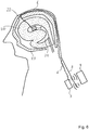
- the FIG. 5 shows the construction and anchoring of the optical stimulation device in the head of a human.
- the implant component 1 with the light sources 3 and the electrodes 4 is placed in a ventricular space 21 and can be washed around by the cerebrospinal fluid present there for cooling the light sources.
- the implant component, and in particular its support structure, are sufficiently permeable to liquids so as not to cause stagnation.
- the implant component is connected via lines 6 to the main electronics 7.
- the main electronics 7 may be implanted under the skin at a suitable location on the body, particularly at a location other than the head.
- the implantation of the implant component 1 in the brain 20 can be minimally invasive.
- the implant component 1 can be introduced, for example, via a path 22 through healthy tissue at a location where hardly any side effects are to be expected. Also possible is an implantation over one of the natural openings of the ventricular system without damaging the brain 20, ie over the illustrated Way 28.
- the FIG. 6 shows the placement of the implant component 1 in the head.
- the implant component 1 is located in a ventricular space 21 of the brain 20.
- a connection for the lines 6 is ensured by a bore 22 in the skull 23 or a natural cranial opening to the outside.
- the main electronics 7 are located under the skin 8, not necessarily below that of the skull 23.
- the main electronics 7 can communicate transdermally with external devices 9.
- FIG. 7 shows, with further details, an embodiment of the implant component 1.
- a support structure 2 constructed in the manner of a grid structure, which supports the light sources 3 and the electrodes 4, is placed in the ventricular space next to the brain 20.
- the support structure 2 is sufficiently permeable to cerebrospinal fluid by being formed with openings and / or channels.
- On and / or in the support structure 2 are organic or crystalline semiconductor light sources 3 and surface electrodes 4, which are contacted by lines 6.
- the arrows indicate the light emission of the light sources 3 in the radial direction with respect to the carrier structure.
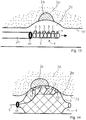
- FIGS. 8 to 10 show possible attachments of the light sources 3 and the electrodes 4 to the support structure 2.
- the light sources 3 and electrodes 4 on the surface of a flexible substrate 18, which is also thermally sufficiently conductive are applied, for example on a silicone material, for example in the form of a silicone tube, or on a MEMS structure.
- the support structure 2 may be formed, for example in the form of a stent, which allows an expansion for anchoring the implant components in the inner cavity of the body.
- the lines 6 can run in the interior of the support structure 2.
- the flexible carrier material 18 may also be on the inside of the carrier structure 2 be arranged.
- the light sources 3 and the electrodes 4 and the lines 6 are incorporated in thin-film or thick-film technology in the thermally conductive flexible substrate 18.
- FIG. 10 shows that the electrodes 4 and the light sources 3 can be fixed directly to the support structure 2 and, accordingly, participate in the change of shape (expansion).
- the FIG. 11 shows a possibility for additional cooling of the light sources via the cerebrospinal fluid.
- the light sources 3 can be equipped with small thermally conductive cooling structures (heat sinks) 19, which deliver the resulting heat to the cerebrospinal fluid.
- the material of the support structure 2 can have a supporting effect, as long as it is sufficiently thermally conductive.
- the support structure 2 can be advantageously used e.g. be formed of a metallic material, similar to conventional stents. As a result, the heat dissipation can be further improved.
- FIG. 12 shows the use of optical fibers (optical fibers 10) in conjunction with optical elements 13 as light sources.
- optical fibers optical fibers
- glass fibers can be used as optical fibers 10.
- such light guides 10 are provided at the end with optical elements 13 such as micro mirrors or prisms, which cause a deflection in the radial light emission direction. The light can then be emitted through the open support structure 2 to the outside, ie in the radial direction with respect to the support structure.
- FIG. 13 shows the introduction of the implant component 1 by means a flexible guide rod 31, for example an endoscope or a catheter.
- the guide rod 31 is mechanically coupled to a coupling element 30 of the implant component.
- an unlocking mechanism which can be arranged on the flexible guide rod and / or on the implant component, this coupling can be canceled in order to remove the guide rod 31 after placing the implant component 1 again. This is done after expansion and corresponding anchoring of the implant component in the inner cavity, here in the ventricular space 21, as in the FIG. 14 shown.
- a stimulation of nerve cells 24 is first roughly positioned in the right place. Subsequently, the support structure 2 is expanded, for example by balloon expansion. As a result, the light sources 3 and the electrodes 4 are pressed against the wall 25 of the ventricular space 21 without damaging them. The guide rod 31 is removed. There remains the line 6 for connecting the implant component 1 with the main electronics 7. It then takes place a programming of the parameter memory of the stimulation device such that, for example, the light source 32 is stored as "activated” and the light source 33 as "not activated”. The nerve cells 24 can then be stimulated by the activatable light sources 32.
- the more remote, non-activatable light sources 33 can remain switched off for energy saving.
- the identification of the activatable light sources can be done by probing individual light sources and by measuring the reaction of the nerve cells 24. The measurement can be carried out via the electrodes 4 themselves or by an otherwise measured response, eg by EEG, behavioral response, functional magnetic resonance imaging, PET, SPECT, pharmacological methods.
Landscapes
- Health & Medical Sciences (AREA)
- Engineering & Computer Science (AREA)
- Biomedical Technology (AREA)
- Life Sciences & Earth Sciences (AREA)
- Pathology (AREA)
- Nuclear Medicine, Radiotherapy & Molecular Imaging (AREA)
- Radiology & Medical Imaging (AREA)
- Animal Behavior & Ethology (AREA)
- General Health & Medical Sciences (AREA)
- Public Health (AREA)
- Veterinary Medicine (AREA)
- Neurosurgery (AREA)
- Biophysics (AREA)
- Electrotherapy Devices (AREA)
- Prostheses (AREA)
Description
- Die Erfindung betrifft eine optische Stimulationseinrichtung zur Stimulation von Nervenzellen gemäß dem Anspruch 1. Die Erfindung betrifft außerdem ein Verfahren zur Programmierung des Parameterspeichers einer Stimulationseinrichtung gemäß dem Anspruch 11.
- Allgemein betrifft die Erfindung das Gebiet der optischen Stimulation von Nervenzellen, d.h. der Stimulation durch Licht. Die Erfindung betrifft damit das Gebiet der Optogenetik. Die Entwicklung der Optogenetik, der Sensibilisierung normaler Nervenzellen für Licht durch genetische Methoden, nähert die Hoffnung, eine Reihe von Erkrankungen durch zeitlich und räumlich selektive Aktivierung oder Inhibition von neuronalen Strukturen mit Licht behandeln zu können. Bisherige Systeme beruhen auf der stereotaktischen Platzierung von Elektroden und Lichtquellen direkt im Hirngewebe bzw. auf der Oberfläche des Gehirns. Dies geht mit aufwändigen chirurgischen Eingriffen und entsprechenden Risiken einher. Die notwendige stereotaktische Planung kompliziert darüber hinaus die breite Anwendbarkeit.
- Außerdem führt die Implantation der lichterzeugenden Strukturen zu einem nicht zu vernachlässigenden Wärmeeintrag im Gehirn. Um eine Gewebeschädigung zu vermeiden, ist die mögliche erreichbare Leistungsdichte der Lichtsignale stark eingeschränkt.
- Aus den Veröffentlichungen
US 2012/0253261 A1 , JIAYI ZHANG ET AL: "Integrated device for optical stimulation and spatiotemporal electrical recording of neural activity in light-sensitized brain tissue", Journal of neural engineering, Institute of physics publishing, Bristol, GB, Bd. 6, Nr. 5, 1, September 2009, Seite 55007,US 2013/046148 A1 undUS 2013/030353 A1 gehen jeweils optische Stimulationseinrichtungen zur Stimulation von Nervenzellen hervor. DieUS 2011/0295331 A1 betrifft ein Cochlea-Implantat. - Der Erfindung liegt daher die Aufgabe zugrunde, eine optische Stimulationseinrichtung zur Stimulation von Nervenzellen anzugeben, die bei vereinfachter Anwendbarkeit zugleich eine höhere Effizienz hat und dadurch den Weg zu einer breiteren Anwendbarkeit optogenetischer Behandlungsmethoden eröffnet.
- Diese Aufgabe wird durch eine optische Stimulationseinrichtung gemäß Anspruch 1 gelöst.
- Die Erfindung hat den Vorteil, dass erstmalig eine optische Stimulationseinrichtung zur Stimulation von Nervenzellen, insbesondere Nervenzellen des Gehirns, angegeben werden kann, die durch nichtinvasive oder minimalinvasive Operationsmethoden zum Einsatz gebracht werden kann. Insbesondere kann die Implantat-Komponente endoskopisch in dem gewünschten inneren Hohlraum des Körpers platziert werden und dort verankert werden, indem eine Fixierung in dem natürlichen inneren Hohlraum durch Expansion der Trägerstruktur in radialer Richtung erfolgt. Die Fixierung kann z.B. durch Ballonexpansion erfolgen, wie von Stents her bekannt. Zur Anbringung und Platzierung der Implantat-Komponente in dem inneren Hohlraum kann z.B. ein flexibler Führungsstab verwendet werden, z.B. in Form eines Katheters. Vorteilhaft kann z.B. ein Ventrikelraum zur Platzierung der Implantat-Komponente genutzt werden. In diesem Fall ist die Einbringung der Implantat-Komponente in den Ventrikelraum nichtinvasiv durchführbar, indem die Wand des Ventrikels nicht durchbrochen
wird, sondern die Platzierung der Implantat-Komponente über die Öffnungen des Ventrikelsystems erfolgt. Es ist auch eine minimalinvasive Platzierung möglich, wenn ein Durchstechen einer Hirnstruktur erfolgt, welche zu möglichst wenigen Nebenwirkungen führt. Die minimalinvasive oder nichtinvasive Natur der erfindungsgemäßen Stimulationseinrichtung erlaubt zudem ihren Austausch bei einem Defekt oder einer Weiterentwicklung der Stimulationseinrichtung. Auch eine Repositionierung ist möglich, ohne dass eine zusätzliche Schädigung im Hirngewebe auftritt. - Die offene Struktur der Trägerstruktur, d.h. die Öffnungen und/oder Kanäle, erlauben ein Durchströmen der Trägerstruktur und damit der Implantat-Komponente nach Implantation im Körper mittels der Körperflüssigkeit, so dass auf natürliche Weise eine Kühlung der Lichtquellen erfolgen kann. Auf diese Weise kann das eingangs genannte Wärmeproblem durch die Lichtquellen gelöst werden. Bei Platzierung der Implantat-Komponente im Ventrikelraum, wie erwähnt, kann direkt die Cerebrospinalflüssigkeit zur Kühlung der Lichtquellen genutzt werden. Hierdurch ist eine besonders effiziente Kühlung möglich, was erheblich höhere abstrahlbare Lichtleistungen ermöglicht. Zugleich können Schädigungen des Hirngewebes durch unzulässige Erwärmung vermieden werden.
- Durch die Lichtabstrahlung in radialer Richtung bezüglich der Trägerstruktur wird das Licht direkt in das umgebende Gewebe abgegeben. Die Lichtabstrahlung muss dabei nicht ausschließlich exakt in radialer Richtung erfolgen. Um einen hohen optischen Wirkungsrad zu erzielen, ist es vorteilhaft, wenn die radiale Komponente der Lichtabstrahlrichtung die überwiegende Komponente ist.
- Mittels der erfindungsgemäßen optischen Stimulationseinrichtung ist eine Behandlung der folgenden Erkrankungen möglich:
- Stimulation des Locus coeruleus:
- Neurodegenerative Erkrankungen wie die Parkinson- und Alzheimererkrankung, welche durch eine frühe Degeneration des LC gekennzeichnet sind,
- schwere psychiatrische Erkrankungsbilder, wie Major Depression, Korsakow Syndrom, Angststörungen, PTSD, die durch veränderte Entladungen des LC gekennzeichnet sind,
- Störungen der Wachheit/Locked-In-Syndroms durch Stimulation des Locus coeruleus bzw. des ARAS,
- bei Narkolepsis oder nach unilateralen cerebralen Infarkten oder Blutungen im Hinstammbereich,
- Störungen autonomer Regelkreise durch Stimulation/Inhibition des Hypothalamus,
- Essstörungen, Überaktivierung der HPA-Achse im Rahmen vieler Erkrankungen, therapieresistente Hypertonie,
- Suchterkrankungen und Psychosen durch indirekte Stimulation frontaler Cortexareale via Aktivierung monoaminerger aszendierender Bahnen (z.B. des medialen Vorderhirnbündels, das von der VTA und dem LC zum Nucleus accumbens zieht),
- Neurodegenerative Erkrankungen/Gedächtnisstörungen durch Beeinflussung des Hippocampus (Platzierung der Implantat-Komponente im Unterhorn des Seitenventrikels)
- Auch ohne genetische Beeinflussung kann die erfindungsgemäße optische Stimulationseinrichtung vorteilhaft eingesetzt werden. Dies wird möglich durch das Vorhandensein endogener lichtsensitiver Nervenzellen im Gehirn von Wirbeltieren. Zusätzlich können thermische Effekte von Infrarotlicht zur fokalen Erwärmung von bestimmten Hirnstrukturen genutzt werden, um deren Aktivität zu modulieren. Ebenfalls möglich ist eine Nutzung der Suppression neuronaler Aktivität durch die bleichenden Eigenschaften von blauem und grünem Licht auf die Flavoproteine der Atmungskette.
- Durch eine direkte Lichtstimulation ohne hinzugefügte optogenetische Proteine erscheint z.B. eine Behandlung von therapieresistenten schweren Depressionen möglich.
- Gemäß einer vorteilhaften Weiterbildung der Erfindung weist die Implantat-Komponente eine Steuerelektronik auf oder ist über Leitungen mit einer entfernt von der Implantat-Komponente angeordneten Steuerelektronik verbunden, wobei die Steuerelektronik zur Signalkonditionierung und/oder Signalverarbeitung der über die Elektroden aufgenommenen Signale und/oder zur Ansteuerung der Lichtquellen eingerichtet ist. Die Steuerelektronik kann einteilig oder mehrteilig ausgebildet sein, z.B. in Form einer direkt auf oder an der Implantat-Komponente angeordneten Headstage-Elektronik und einer entfernt angeordneten Hauptelektronik, die über Leitungen mit der Implantat-Komponente und insbesondere dessen Headstage-Elektronik verbunden ist. Auf diese Weise kann die erforderliche Elektronik soweit wie notwendig direkt an der Implantat-Komponente angeordnet werden, z.B. um eine unmittelbare Signalkonditionierung der Signale der Elektroden zu ermöglichen. Hierdurch kann die Headstage-Elektronik baulich klein gehalten werden. Weitere erforderliche Bauteile können dann in der Hauptelektronik untergebracht werden.
- Die Lichtquellen können elektrische Lichtquellen sein, z.B. in Form von Halbleiterlichtquellen, insbesondere in Form von Leuchtdioden (LED) oder Laserdioden. Die Lichtquellen können auch passive Lichtquellen sein, z.B. in Form von Lichtaustrittsflächen von Lichtleitern oder an Lichtleitern angeordneten Prismen, Mikrospiegeln oder sonstige Optiken. Im Falle passiver Lichtquellen können die zu den Lichtquellen führenden Leitungen insbesondere Lichtleiter sein, z.B. in Form von Glasfasern. Dies hat den Vorteil, dass die optische Stimulationseinrichtung MRT-tauglich ist, d.h. die Aufnahmen mittels eines Magnetresonanztomographen (MRT) nicht stört. Sofern als Lichtquellen elektrische Lichtquellen, die an oder in der Implantat-Komponente angeordnet sind, eingesetzt werden, werden als Leitungen elektrische Leiter (Kabel) eingesetzt. Die an der Trägerstruktur befestigten Lichtquellen können auch eine Kombination aus elektrischen Lichtquellen und passiven Lichtquellen sein.
- Gemäß einer vorteilhaften Weiterbildung der Erfindung sind die Lichtquellen in vordefinierter Lage bezüglich der Elektroden an der Trägerstruktur befestigt.
- Gemäß einer vorteilhaften Weiterbildung der Erfindung weist die Steuerelektronik einen Parameterspeicher auf, in dem für jede Lichtquelle eine Information gespeichert ist, ob die Lichtquelle zu Stimulationszwecken aktivierbar ist oder nicht. Dies hat den Vorteil, dass die Platzierung der Implantat-Komponente in dem inneren Hohlraums des Körpers vereinfacht wird, da keine besonders hohe Positioniergenauigkeit erforderlich ist. Stattdessen kann die Implantat-Komponente mit den Lichtquellen sozusagen "überbestückt" sein, d.h. mehr Lichtquellen aufweisen als für die eigentliche Nervenstimulation erforderlich ist. Durch die bekannte Lage der Lichtquellen bezüglich der Elektroden an der Trägerstruktur kann durch probeweises Ansteuern einzelner Lichtquellen und Empfang der Elektrodensignale getestet werden, welche Lichtquelle am Günstigsten bezüglich der Nervenzellen ausgerichtet sind. Für diese kann dann in dem Parameterspeicher die Information gespeichert werden, dass die Lichtquelle zur Stimulationszwecken aktivierbar ist. Für die übrigen Lichtquellen kann die Information gespeichert werden, dass sie zu Stimulationszwecken nicht aktivierbar ist und dementsprechend im späteren Betrieb der optischen Stimulationseinrichtung ausgeschaltet bleibt. Hierdurch werden die elektrische Aktivierung und damit der hiermit verbundene Wärmeeintrag auf das notwendige Maß begrenzt. Es erfolgt keine unnötige Aktivierung von Lichtquellen, die keinen oder keinen wesentlichen Einfluss auf die Nervenzellen haben.
- Die Identifikation der aktivierbaren Lichtquellen kann durch Messung über die Elektroden selbst oder durch eine anderweitig gemessene Antwort durchgeführt werden, z.B. durch EEG, Verhaltensantwort, funktionelle Kernspintomographie, PET, SPECT, pharmakologische Methoden. Wird die Identifikation der aktivierbaren Lichtquellen nicht durch Messung über die Elektroden durchgeführt, ist es nicht unbedingt erforderlich, die Lichtquellen in vordefinierter Lage bezüglich der Elektroden an der Trägerstruktur anzuordnen.
- Gemäß einer vorteilhaften Weiterbildung der Erfindung weist die Trägerstruktur im nichtexpandierten Zustand einen Umfang von weniger als 10 mm auf, insbesondere weniger als 6 mm. Dies hat den Vorteil, dass eine minimalinvasive oder nichtinvasive Platzierung der Implantat-Komponente bei nahezu jedem Körper eines Lebewesens möglich ist.
- Gemäß einer vorteilhaften Weiterbildung der Erfindung weist die Trägerstruktur ein Material mit hoher Wärmeleitfähigkeit auf. Insbesondere ist die Wärmeleitfähigkeit größer als 10 W/m•K. Dies hat den Vorteil, dass die Trägerstruktur zusätzlich zur Kühlung beiträgt, indem sie die an den Lichtquellen entstehende Wärme besser auf die als Kühlflüssigkeit dienende Körperflüssigkeit überträgt, die sich im inneren Hohlraum zusammen mit der Implantat-Komponente befindet.
- Gemäß einer vorteilhaften Weiterbildung der Erfindung weisen eine, mehrere oder alle Lichtquellen thermisch leitfähige Kühlkörper auf. Hierdurch wird die Wärmeableitung von den Lichtquellen weiter verbessert.
- Gemäß einer vorteilhaften Weiterbildung der Erfindung weist die Implantat-Komponente ein Kupplungselement auf, über das die Implantat-Komponente mit einem zur Durchführung des Implantationsvorgangs mit der Implantat-Komponente zu koppelnden flexiblen Führungsstab koppelbar ist, wobei die Kopplung des Kupplungselements mit dem flexiblen Führungsstab durch Betätigung eines Entriegelungsmechanismus lösbar ist. Dies ist zusätzlich förderlich für eine minimalinvasive oder nichtinvasive Platzierung der Implantat-Komponente im inneren Hohlraum des Körpers. Der flexible Führungsstab kann z.B. wie ein Endoskop oder ein Katheter ausgebildet sein. Durch den Entriegelungsmechanismus, der z.B. von einem Handgriff des flexiblen Führungsstabs fernbedienbar sein kann, kann nach korrekter Platzierung der Implantat-Komponente in dem inneren Hohlraum des Körpers der Führungsstab davon gelöst werden und wieder aus dem Körper entfernt werden. Zuvor kann über einen Expansionsmechanismus, der ebenfalls über den flexiblen Führungsstab auslösbar ist, die Trägerstruktur zur Fixierung der Implantat-Komponente in dem inneren Hohlraum des Körpers expandiert werden.
- Gemäß einer vorteilhaften Weiterbildung der Erfindung sind einige oder alle Lichtquellen individuell aktivierbar. Dies hat den Vorteil, dass durch gezielte Ansteuerung bestimmter Lichtquellen besondere Behandlungsverfahren realisiert werden können, die bei simultaner Ansteuerung aller Lichtquellen nicht möglich wären. Hierdurch wird die Einsatzbreite der optischen Stimulationseinrichtung weiter verbessert.
- Gemäß einer vorteilhaften Weiterbildung der Erfindung sind die Lichtquellen und/oder die Elektroden auf einem flexiblen Trägermaterial befestigt, das an der Trägerstruktur befestigt ist. Das flexible Trägermaterial kann z.B. ein Silikonschlauch oder eine MEMS-Struktur sein. Das flexible Trägermaterial ist dabei zumindest soweit mit Öffnungen und/oder Kanälen ausgebildet, dass der gewünschte Durchfluss der Körperflüssigkeit gewährleistet ist. Hierdurch wird die Herstellbarkeit der optischen Stimulationseinrichtung verbessert. So können die Lichtquellen, z.B. in Form von Leuchtdioden oder Laserdioden, auf eine Folie oder ein Silikonmaterial aufgedrückt werden und/oder fadenartig, ähnlich einer Schnur, auf die Trägerstruktur aufgefädelt werden.
- Die Erfindung betrifft gemäß Anspruch 11 ferner ein Verfahren zur Programmierung des Parameterspeichers einer Stimulationseinrichtung der zuvor genannten Art, wobei zunächst alle Lichtquellen zur Lichtabgabe betätigt werden, die daraufhin mittels der Elektroden erfassten Signale ausgewertet werden oder durch andere Nervensignal-Erfassungsmethoden erfasste Signale ausgewertet werden, hieraus zukünftig aktivierbare Lichtquellen aus der Gesamtmenge der vorhandenen Lichtquellen bestimmt werden und für diese Lichtquellen im Parameterspeicher die Kennung "aktivierbar" gespeichert wird und für alle übrigen Lichtquellen die Kennung "nicht-aktivierbar" gespeichert wird. Mit diesem Verfahren vereinfacht sich die genaue Platzierung und Justierung der Implantat-Komponente in dem inneren Hohlraum des Körpers, da zunächst nur eine Grobplatzierung in Bezug auf die stimulierenden Nervenzellen erforderlich ist. Durch die beschriebene Programmierung des Parameterspeichers werden dann die Lichtquellen der Implantat-Komponente detektiert, die eine funktionelle Wirkung auf die Stimulation der Nervenzellen haben. Die übrigen Lichtquellen werden dann fortan nicht benötigt und können als "nicht-aktivierbar" gekennzeichnet werden. Eine weitere mechanische Feinplatzierung der Implantat-Komponente ist dann nicht erforderlich. Ebenfalls beschrieben wird ein Verfahren zum Implantieren einer optischen Stimulationseinrichtung in einem Körper eines Menschen oder Tieres, wobei eine Implantat-Komponente der optischen Stimulationseinrichtung endoskopisch in einem Ventrikelraum des Körpers platziert und dort fixiert wird. Hierbei kann insbesondere eine Implantat-Komponente einer optischen Stimulationseinrichtung der zuvor beschriebenen Art eingesetzt werden. Hierdurch können die zuvor erwähnten Vorteile realisiert werden.
- Gemäß einer vorteilhaften Weiterbildung der Erfindung erfolgt das Fixieren der Implantat-Komponente im Ventrikelraum durch Expandieren einer Trägerstruktur der Implantat-Komponente.
- Zur endoskopischen Platzierung des Katheters wird folgendes Verfahren, ausgeführt am Beispiel aquäduktnaher Zielstrukturen, vorgeschlagen: Es wird wie beim endoskopischen Stenting einer Aquäduktstenose zunächst eine kleine Trepanation (1,5 bis 2 cm im Durchmesser) ca. 2 bis 4 cm anterior der koronaren Sutur und 2 cm rechts der Mittellinie vorgenommen. Anschließend wird über ein rigides oder flexibles Neuroendoskop das Vorderhorn des rechten lateralen Ventrikels erreicht und schließlich ein French Fogarty-Ballon-Katheter über das Foramen Monroe und den III. Ventrikel in das Aquädukt eingebracht. Die exakte Platzierung der lichtemittierenden Spitze des Katheters, in Bezug auf die Zielstruktur, erfolgt entsprechend einer vorher tomographisch genau bestimmten Distanz zu einem Fixpunkt im Aquädukt. Fixiert wird der Katheter über die Expansion des Ballons im Aquädukt. So können Zielstrukturen in der Umgebung des IV. Ventrikels, insbesondere der Locus coeruleus erreicht werden. Die Navigation kann vorher mittels Software trainiert werden.
- Ein anderer möglicher Weg zum IV. Ventrikel ist von occipital via der natürlichen Öffnungen zum äußeren Liquorraum. Durch die Apertura mediana ventriculi quarti ist der IV: Ventrikel mit der Cisterna cerebollomedullaris verbunden und durch die Apertura lateralis beidseits mit der Cisterna pontis. Positionierung und Verankerung erfolgen analog der vorher beschriebenen Weise.
- Die Erfindung wird nachfolgend anhand von Ausführungsbeispielen unter Verwendung von Zeichnungen näher erläutert.
- Die
Figur 1 zeigt ein Beispiel eines allgemeinen Systemaufbaus der optischen Stimulationseinrichtung. Erkennbar ist eine z.B. als Stent oder Katheter ausgebildete Trägerstruktur 2, an der Lichtquellen 3 und Oberflächenelektroden 4 befestigt sind. Hierdurch wird eine Implantat-Komponente 1 bereitgestellt. Die Implantat-Komponente 1 weist eine direkt damit verbundene Headstage-Elektronik 5 auf, die eine Signalkonditionierung und Verarbeitung für ein- und ausgehende Signale vornimmt, z.B. Impedanzwandlung, Verstärkung, Digitalisierung, Ansteuerung der Lichtquellen. Hierbei können Lichtquellen 3 z.B. in Form von LEDs direkt auf der Trägerstruktur 2 angeordnet sein, oder in Form von Laserdioden in der Headstage-Elektronik 5. Deren Licht wird dann über Lichtleiter zu den in der Figur mit den Lichtquellen 3 dargestellten Positionen herausgeführt. - Die Headstage-Elektronik 5 ist über Leitungen 6 mit einer Hauptelektronik 7 des Systems verbunden. Die Hauptelektronik 7 übernimmt die Datenkommunikation mit externen Geräten 9 durch die Haut 8 und liefert Strom für den Betrieb der Lichtquellen und der Headstage-Elektronik 5. Die Hauptelektronik 7 kann ebenfalls die Interpretation der Signale und eine mögliche Rückkopplung an die Lichtquellen durchführen, sowie Daten intern speichern und auswerten. Sofern Laserdioden eingesetzt werden, können diese auch in der Hauptelektronik angeordnet sein und über Lichtleiter mit der Implantat-Komponente 1 verbunden sein.
- Die Headstage-Elektronik 5 sowie die Hauptelektronik 7 bilden zusammen eine Steuerelektronik der Stimulationseinrichtung. Diese weist einen Parameterspeicher auf, in dem für jede Lichtquelle 3 ein Speicherplatz, z.B. in Form eines Bits oder Bytes, vorgesehen ist. In diesem Speicherplatz kann für jede Lichtquelle individuell eine Information gespeichert werden, ob die Lichtquelle zu Stimulationszwecken aktivierbar ist oder nicht.
- Wie in
Figur 2 erkennbar ist, können die Lichtquellen 3 bzw. deren Laserdioden in Serie geschaltet sein, was den Vorteil hat, dass die Verkabelung einfacher wird und weniger Leitungen erforderlich sind. - Wie in
Figur 3 erkennbar ist, können die Lichtquellen 3 bzw. deren Laserdioden auch einzeln durch die Headstage-Elektronik 5 und/oder die Hauptelektronik 7 gesteuert werden. Dies hat den Vorteil, dass die Stimulation auf einen bestimmten Bereich beschränkt werden kann, indem nur einige der vorhandenen Lichtquellen aktiviert werden. - Die
Figur 4 zeigt den Systemaufbau bei Verwendung von Lichtleitern. Als Lichtquelle ist ein optisches Bauteil 13 vorgesehen, das am Ende eines Lichtleiters 10 angeordnet ist. Das optische Bauteil 13 kann z.B. ein Mikrospiegel, ein Prisma oder ein ähnliches die Abstrahlrichtung änderndes optisches Bauteil sein. Das optische Bauteil 13 reflektiert das Licht in einem Winkel in das Körpergewebe, welches durch den Lichtleiter 10 und ggf. eine eingangsseitig an dem Lichtleiter 10 angeordnete Optik 11 durch einen Laseremitter 12 bereitgestellt wird. Für die Ansteuerung des Laseremitters 12 ist eine Treiberelektronik 17 vorgesehen, die z.B. Teil der Hauptelektronik 7 sein kann. Durch die Verwendung von Lichtleitern wird die optische Stimulationseinrichtung insbesondere im Hinblick auf die MRT-Tauglichkeit verbessert. - Die
Figur 5 zeigt den Aufbau und die Verankerung der optischen Stimulationseinrichtung im Kopf eines Menschen. Die Implantat-Komponente 1 mit den Lichtquellen 3 und den Elektroden 4 wird in einem Ventrikelraum 21 platziert und kann von der dort vorhandenen Cerebrospinalflüssigkeit zur Kühlung der Lichtquellen umspült werden. Die Implantat-Komponente und insbesondere dessen Trägerstruktur sind hinreichend permeabel für Flüssigkeiten, um keine Stauung hervorzurufen. Die Implantat-Komponente ist über die Leitungen 6 mit der Hauptelektronik 7 verbunden. Die Hauptelektronik 7 kann unter der Haut an einer geeigneten Stelle des Körpers implantiert werden, insbesondere an einer anderen Stelle als im Kopf. Die Implantation der Implantat-Komponente 1 im Gehirn 20 kann minimalinvasiv erfolgen. Die Implantat-Komponente 1 kann z.B. über einen Weg 22 durch gesundes Gewebe an einer Stelle eingebracht werden, an der kaum Nebenwirkungen zu erwarten sind. Ebenfalls möglich ist eine Implantation über eine der natürlichen Öffnungen des Ventrikelsystems ohne Beschädigung des Gehirns 20, d.h. über den dargestellten Weg 28. - Die
Figur 6 zeigt die Platzierung der Implantat-Komponente 1 im Kopf. Die Implantat-Komponente 1 befindet sich in einem Ventrikelraum 21 des Gehirns 20. Eine Verbindung für die Leitungen 6 ist durch eine Bohrung 22 im Schädel 23 oder eine natürliche Schädelöffnung nach außen gewährleistet. Die Hauptelektronik 7 befindet sich unter der Haut 8, nicht notwendigerweise unter der des Schädels 23. Die Hauptelektronik 7 kann mit externen Geräten 9 transdermal kommunizieren. - Die
Figur 7 zeigt mit weiteren Details eine Ausführungsform der Implantat-Komponente 1. Eine gitterstrukturartig aufgebaute Trägerstruktur 2, die die Lichtquellen 3 und die Elektroden 4 trägt, ist im Ventrikelraum neben dem Gehirn 20 platziert. Die Trägerstruktur 2 ist hinreichend durchlässig für Cerebrospinalflüssigkeit, indem sie mit Öffnungen und/oder Kanälen ausgebildet ist. Auf und/oder in der Trägerstruktur 2 befinden sich organische oder kristalline Halbleiterlichtquellen 3 und Oberflächenelektroden 4, die durch Leitungen 6 kontaktiert werden. Durch die Pfeile ist die Lichtabstrahlung der Lichtquellen 3 in radialer Richtung bezüglich der Trägerstruktur gekennzeichnet. - Die
Figur 8 bis 10 zeigen mögliche Anbringungen der Lichtquellen 3 und der Elektroden 4 an der Trägerstruktur 2. In derFigur 8 ist wiedergegeben, dass die Lichtquellen 3 und Elektroden 4 auf der Oberfläche eines flexiblen Trägermaterials 18, das zudem thermisch hinreichend leitfähig ist, aufgebracht sind, z.B. auf einem Silikonmaterial, z.B. in Form eines Silikonschlauchs, oder auf einer MEMS-Struktur. Innerhalb des Trägermaterials 18 befindet sich die Trägerstruktur 2. Die Trägerstruktur 2 kann z.B. in Form eines Stents ausgebildet sein, die eine Expansion zur Verankerung der Implantat-Komponenten im inneren Hohlraum des Körpers erlaubt. Die Leitungen 6 können im Inneren der Trägerstruktur 2 verlaufen. Alternativ kann das flexible Trägermaterial 18 auch an der Innenseite der Trägerstruktur 2 angeordnet sein. - In der
Figur 9 ist erkennbar, dass die Lichtquellen 3 und die Elektroden 4 sowie die Leitungen 6 in Dünnschicht- oder Dickschichttechnik in das thermisch leitfähige flexible Trägermaterial 18 eingearbeitet sind. - Der
Figur 10 zeigt, dass die Elektroden 4 und die Lichtquellen 3 direkt an der Trägerstruktur 2 befestigt sein können und dementsprechend die Formänderung (Expansion) mitmachen. - Die
Figur 11 zeigt eine Möglichkeit zur zusätzlichen Kühlung der Lichtquellen über die Cerebrospinalflüssigkeit. Die Lichtquellen 3 können mit kleinen thermisch leitfähigen Kühlstrukturen (Kühlkörper) 19 ausgestattet sein, welche die entstehende Wärme an die Cerebrospinalflüssigkeit abgeben. Hierbei kann zusätzlich das Material der Trägerstruktur 2 unterstützend wirken, sofern es hinreichen wärmeleitfähig ist. - Die Trägerstruktur 2 kann vorteilhaft z.B. aus einem metallischen Material gebildet sein, ähnlich wie übliche Stents. Hierdurch kann die Wärmeableitung weiter verbessert werden.
- Die
Figur 12 zeigt den Einsatz von optischen Fasern (Lichtleitern 10) in Verbindung mit optischen Elementen 13 als Lichtquellen. Um eine MRT-Tauglichkeit und zusätzlich um höhere optische Leistungen zu erreichen, können Glasfasern als Lichtleiter 10 eingesetzt werden. Um das Licht in das umgebende Gewebe zu leiten, sind solche Lichtleiter 10 am Ende mit optischen Elementen 13 wie Mikrospiegeln bzw. Prismen ausgestattet, welche eine Umlenkung in die radiale Lichtabstrahlrichtung bewirken. Das Licht kann dann durch die offene Trägerstruktur 2 nach außen abgestrahlt werden, d.h. in radialer Richtung bezüglich der Trägerstruktur. - Die
Figur 13 zeigt die Einbringung der Implantat-Komponente 1 mittels eines flexiblen Führungsstabs 31, z.B. eines Endoskops oder eines Katheters. Der Führungsstab 31 ist mit einem Kupplungselement 30 der Implantat-Komponente mechanisch gekoppelt. Über einen Entriegelungsmechanismus, der an dem flexiblen Führungsstab und/oder an der Implantat-Komponente angeordnet sein kann, kann diese Kopplung aufgehoben werden, um den Führungsstab 31 nach Platzierung der Implantat-Komponente 1 wieder zu entfernen. Dies erfolgt nach Expansion und dementsprechender Verankerung der Implantat-Komponente in dem inneren Hohlraum, hier im Ventrikelraum 21, wie in derFigur 14 dargestellt. - Wie aus der
Figur 14 zusätzlich erkennbar ist, soll mittels der Implantat-Komponente eine Stimulation von Nervenzellen 24 erfolgen. Hierfür wird die Implantat-Komponente 1 innerhalb des Gehirns 20 mittels des Führungsstabs 31 zunächst grob an der richtigen Stelle positioniert. Anschließend wird die Trägerstruktur 2 expandiert, z.B. durch Ballonexpansion. Hierdurch werden die Lichtquellen 3 und die Elektroden 4 gegen die Wand 25 des Ventrikelraums 21 gedrückt, ohne diese zu beschädigen. Der Führungsstab 31 wird entfernt. Es verbleibt die Leitung 6 zur Verbindung der Implantat-Komponente 1 mit der Hauptelektronik 7. Es erfolgt dann eine Programmierung des Parameterspeichers der Stimulationseinrichtung derart, dass z.B. die Lichtquelle 32 als "aktivierbar" gespeichert wird und die Lichtquelle 33 als "nicht aktivierbar". Die Nervenzellen 24 können dann durch die aktivierbaren Lichtquellen 32 stimuliert werden. Die weiter entfernt liegenden, nicht aktivierbaren Lichtquellen 33 können zur Energieeinsparung ausgeschaltet bleiben. Die Identifikation der aktivierbaren Lichtquellen kann durch probeweises Aktivieren einzelner Lichtquellen und durch Messung der Reaktion der Nervenzellen 24 erfolgen. Die Messung kann über die Elektroden 4 selbst oder durch eine anderweitig gemessene Antwort durchgeführt werden, z.B. durch EEG, Verhaltensantwort, funktionelle Kernspintomographie, PET, SPECT, pharmakologische Methoden.
Claims (11)
- Optische Stimulationseinrichtung zur Stimulation von Nervenzellen, wobei die Stimulationseinrichtung wenigstens eine Implantat-Komponente (1) aufweist, die zum Implantieren in einem von einer Körperflüssigkeit durchflossenen natürlichen inneren Hohlraum (21) des Körpers eines Lebewesens eingerichtet ist, mit folgenden Merkmalen:a) die Implantat-Komponente (1) weist wenigstens eine Trägerstruktur (2) auf, die zur Fixierung in dem natürlichen inneren Hohlraum (21) in radialer Richtung expandierbar ist,b) an der Trägerstruktur (2) ist eine Vielzahl von Lichtquellen (3, 13) befestigt, die zur Lichtabstrahlung in radialer Richtung bezüglich der Trägerstruktur (2) eingerichtet sind,c) an der Trägerstruktur (2) sind eine Vielzahl von Elektroden (4) befestigt, die zur Erfassung elektrischer Körpersignale eingerichtet sind,d) die Trägerstruktur (2) weist mehrere Öffnungen und/oder Kanäle auf, die nach Implantation im Körper von Körperflüssigkeit durchströmbar sind, sodass die Lichtquellen kühlbar sind, indem sie von der Körperflüssigkeit umspült werden.
- Stimulationseinrichtung nach Anspruch 1, dadurch gekennzeichnet, dass die Implantat-Komponente (1) eine Steuerelektronik (5, 7) aufweist und/oder eine entfernt von der Implantat-Komponente (1) anordenbare und mit dieser über Leitungen (6) verbindbare Steuerelektronik (5, 7) aufweist, wobei die Steuerelektronik (5, 7) zur Signalkonditionierung und/oder Signalverarbeitung der über die Elektroden (4) aufgenommenen Signale und/oder zur Ansteuerung der Lichtquellen (3) eingerichtet ist.
- Stimulationseinrichtung nach dem vorhergehenden Anspruch, dadurch gekennzeichnet, dass die Steuerelektronik (5, 7) einen Parameterspeicher aufweist, in dem für jede Lichtquelle (3) eine Information gespeichert ist, ob die Lichtquelle (3) zu Stimulationszwecken aktivierbar ist oder nicht.
- Stimulationseinrichtung nach dem vorhergehenden Anspruch, dadurch gekennzeichnet, dass die Lichtquellen (3) in vordefinierter Lage bezüglich der Elektroden (4) an der Trägerstruktur (2) befestigt sind.
- Stimulationseinrichtung nach einem der vorhergehenden Ansprüche, dadurch gekennzeichnet, dass die Trägerstruktur (2) im nichtexpandierten Zustand einen Umfang von weniger als 10 mm aufweist, insbesondere weniger als 6 mm.
- Stimulationseinrichtung nach einem der vorhergehenden Ansprüche, dadurch gekennzeichnet, dass die Trägerstruktur (2) ein Material mit hoher Wärmeleitfähigkeit aufweist, insbesondere mit einer Wärmeleitfähigkeit größer als 10 W/m·K.
- Stimulationseinrichtung nach einem der vorhergehenden Ansprüche, dadurch gekennzeichnet, dass eine, mehrere oder alle Lichtquellen (3) thermisch leitfähige Kühlkörper (19) aufweisen.
- Stimulationseinrichtung nach einem der vorhergehenden Ansprüche, dadurch gekennzeichnet, das die Implantat-Komponente (1) ein Kupplungselement (30) aufweist, über das die Implantat-Komponente (1) mit einem zur Durchführung des Implantationsvorgangs mit der Implantat-Komponente (1) zu koppelnden flexiblen Führungsstab (31) koppelbar ist, wobei die Kopplung des Kupplungselements (30) mit dem flexiblen Führungsstab (31) durch Betätigung eines Entriegelungsmechanismus lösbar ist.
- Stimulationseinrichtung nach einem der vorhergehenden Ansprüche, dadurch gekennzeichnet, dass einige oder alle Lichtquellen (3) individuell aktivierbar sind.
- Stimulationseinrichtung nach einem der vorhergehenden Ansprüche, dadurch gekennzeichnet, dass die Lichtquellen (3) und/oder die Elektroden (4) auf einem flexiblen Trägermaterial (18) befestigt sind, das an der Trägerstruktur (2) befestigt ist.
- Verfahren zur Programmierung des Parameterspeichers einer Stimulationseinrichtung nach Anspruch 3, dadurch gekennzeichnet, dass zunächst alle Lichtquellen (3) zur Lichtabgabe betätigt werden, die daraufhin mittels der Elektroden (4) erfassten Signale ausgewertet werden oder durch andere Nervensignal-Erfassungsmethoden erfasste Signale ausgewertet werden, hieraus zukünftig aktivierbare Lichtquellen (3) aus der Gesamtmenge der vorhandenen Lichtquellen (3) bestimmt werden und für diese Lichtquellen (3) im Parameterspeicher die Kennung "aktivierbar" gespeichert wird und für alle übrigen Lichtquellen (3) die Kennung "nicht-aktivierbar" gespeichert wird.
Applications Claiming Priority (2)
| Application Number | Priority Date | Filing Date | Title |
|---|---|---|---|
| DE102014107298.7A DE102014107298A1 (de) | 2014-05-23 | 2014-05-23 | Optische Stimulationseinrichtung und Verfahren zur Programmierung |
| PCT/EP2015/061400 WO2015177345A1 (de) | 2014-05-23 | 2015-05-22 | Optische stimulationseinrichtung und verfahren zur programmierung |
Publications (2)
| Publication Number | Publication Date |
|---|---|
| EP3145586A1 EP3145586A1 (de) | 2017-03-29 |
| EP3145586B1 true EP3145586B1 (de) | 2018-07-04 |
Family
ID=53276101
Family Applications (1)
| Application Number | Title | Priority Date | Filing Date |
|---|---|---|---|
| EP15726073.8A Active EP3145586B1 (de) | 2014-05-23 | 2015-05-22 | Optische stimulationseinrichtung und verfahren zur programmierung |
Country Status (4)
| Country | Link |
|---|---|
| US (1) | US10751544B2 (de) |
| EP (1) | EP3145586B1 (de) |
| DE (1) | DE102014107298A1 (de) |
| WO (1) | WO2015177345A1 (de) |
Families Citing this family (5)
| Publication number | Priority date | Publication date | Assignee | Title |
|---|---|---|---|---|
| US9950188B2 (en) * | 2012-05-31 | 2018-04-24 | Color Seven Co., Ltd. | Apparatus for relaxing smooth muscles of human body |
| KR102089634B1 (ko) * | 2014-11-07 | 2020-03-16 | 주식회사 칼라세븐 | 광선치료용 스마트폰 인터페이스 장치 |
| DE102017120949A1 (de) * | 2017-09-11 | 2019-03-14 | Marc-Eric Halatsch | Implantatsystem |
| EP3717066A1 (de) * | 2017-11-30 | 2020-10-07 | Case Western Reserve University | Modulation der neuronalen aktivität in einer hirnstammschaltung mit licht |
| FR3104449B1 (fr) * | 2019-12-12 | 2021-12-24 | Commissariat Energie Atomique | Dispositif d'illumination implantable dans un être vivant |
Family Cites Families (16)
| Publication number | Priority date | Publication date | Assignee | Title |
|---|---|---|---|---|
| US9216239B2 (en) * | 2001-06-08 | 2015-12-22 | Leo Rubin | Medical device for intra-lumenal delivery of pharmaceutical agents |
| WO2006041738A2 (en) * | 2004-10-04 | 2006-04-20 | Cyberkinetics Neurotechnology Systems, Inc. | Biological interface system |
| US8792978B2 (en) * | 2010-05-28 | 2014-07-29 | Lockheed Martin Corporation | Laser-based nerve stimulators for, E.G., hearing restoration in cochlear prostheses and method |
| KR20080093453A (ko) * | 2006-02-07 | 2008-10-21 | 미쓰비시 타나베 파마 코퍼레이션 | 4-아실아미노피리딘 유도체 매개된 신경조직발생 |
| MX2009003931A (es) * | 2006-10-11 | 2009-04-24 | Light Sciences Oncology Inc | Sistema de suministro de luz. |
| US20080281305A1 (en) * | 2007-05-10 | 2008-11-13 | Cardiac Pacemakers, Inc. | Method and apparatus for relieving angina symptoms using light |
| US20090112278A1 (en) * | 2007-10-30 | 2009-04-30 | Neuropace, Inc. | Systems, Methods and Devices for a Skull/Brain Interface |
| WO2011057276A2 (en) | 2009-11-09 | 2011-05-12 | University Of Utah Research Foundation | Three-dimensional penetrating optical-electrical neural interface for selective stimulation and recording |
| US9936574B2 (en) * | 2009-12-16 | 2018-04-03 | The Board Of Trustees Of The University Of Illinois | Waterproof stretchable optoelectronics |
| US20120253261A1 (en) * | 2011-03-29 | 2012-10-04 | Medtronic, Inc. | Systems and methods for optogenetic modulation of cells within a patient |
| WO2013016392A1 (en) * | 2011-07-25 | 2013-01-31 | Neuronexus Technologies, Inc. | Neuromodulation transfection system with passive fluid delivery |
| DE102012002663A1 (de) * | 2012-02-10 | 2013-08-14 | Albert-Ludwigs-Universität Freiburg | Gewebesonde und Verfahren zu ihrer Herstellung und Verwendung |
| WO2013136337A1 (en) * | 2012-03-15 | 2013-09-19 | Gema Medical Ltd | A sensing system, device and methods for gastroparesis monitoring |
| DE102012110358B4 (de) * | 2012-10-30 | 2016-04-07 | Leibniz-Institut für Neurobiologie Magdeburg | Mikroelektrodenarray |
| US20160073887A1 (en) * | 2013-04-11 | 2016-03-17 | Brown University | Optoelectronic device to write-in and read-out activity in brain circuits |
| US10220092B2 (en) * | 2013-04-29 | 2019-03-05 | The Board Of Trustees Of The Leland Stanford Junior University | Devices, systems and methods for optogenetic modulation of action potentials in target cells |
-
2014
- 2014-05-23 DE DE102014107298.7A patent/DE102014107298A1/de not_active Withdrawn
-
2015
- 2015-05-22 EP EP15726073.8A patent/EP3145586B1/de active Active
- 2015-05-22 US US15/313,334 patent/US10751544B2/en active Active
- 2015-05-22 WO PCT/EP2015/061400 patent/WO2015177345A1/de not_active Ceased
Non-Patent Citations (1)
| Title |
|---|
| None * |
Also Published As
| Publication number | Publication date |
|---|---|
| WO2015177345A1 (de) | 2015-11-26 |
| US20170189712A1 (en) | 2017-07-06 |
| DE102014107298A1 (de) | 2015-11-26 |
| US10751544B2 (en) | 2020-08-25 |
| EP3145586A1 (de) | 2017-03-29 |
Similar Documents
| Publication | Publication Date | Title |
|---|---|---|
| Hanson et al. | The “sewing machine” for minimally invasive neural recording | |
| EP3145586A1 (de) | Optische stimulationseinrichtung und verfahren zur programmierung | |
| US7283856B2 (en) | Implantable lead system with seed electrodes | |
| EP3184146B1 (de) | Effiziente bereitstellung von phototherapie mit optischer lichtfaser | |
| JP6908328B2 (ja) | 脳プローブ自動誘導システム | |
| DE102012110358B4 (de) | Mikroelektrodenarray | |
| DE102005032989A1 (de) | Extraokulares Epiretinal-Implantat | |
| US5928143A (en) | Implantable multi-electrode microdrive array | |
| Lowery et al. | Restoration of vision using wireless cortical implants: The Monash Vision Group project | |
| KR20120088501A (ko) | 액정폴리머 기반의 전광극 신경 인터페이스 및 그 제조 방법 | |
| EP2537463A1 (de) | Medizinisches Sensorsystem | |
| WO2008043439A1 (de) | Vorrichtung mit einem grundkörper | |
| EP3917435B1 (de) | Bahnführung mit doppel-x-y-schiebetischen | |
| WO2014126927A1 (en) | Injectable and implantable cellular-scale electronic devices | |
| DE102009015389A1 (de) | Aktives Retina-Implantat | |
| DE19938549A1 (de) | Mikrosondensystem | |
| WO2021067905A1 (en) | Multilayer and bouquet fiber-based neural probes and methods of making and uses thereof | |
| Chen et al. | Pulse-width modulation of optogenetic photo-stimulation intensity for application to full-implantable light sources | |
| DE102016211969B4 (de) | Medizinische Vorrichtung zum Durchführen einer Biopsie und Verfahren zum Herstellen der medizinischen Vorrichtung | |
| Schröder et al. | The DREAM implant: A lightweight, modular, and cost-effective implant system for chronic electrophysiology in head-fixed and freely behaving mice | |
| EP1209946A2 (de) | Gerät und Verfahren zur präoperativen Demostration implantierbarer Hörsysteme | |
| CH702877A2 (de) | Einrichtung zur lichteinwirkung auf den körper eines lebewesens. | |
| Chen et al. | Custom skull cap with precision guides for deep insertion of cellular-scale microwire into rat brain | |
| WO1997047240A1 (de) | System zur positionserfassung mit einem marker und marker zur anwendung in einem solchen system | |
| WO2014142741A1 (en) | Combination probe for localizing, recording and stimulating a target tissue |
Legal Events
| Date | Code | Title | Description |
|---|---|---|---|
| STAA | Information on the status of an ep patent application or granted ep patent |
Free format text: STATUS: THE INTERNATIONAL PUBLICATION HAS BEEN MADE |
|
| PUAI | Public reference made under article 153(3) epc to a published international application that has entered the european phase |
Free format text: ORIGINAL CODE: 0009012 |
|
| STAA | Information on the status of an ep patent application or granted ep patent |
Free format text: STATUS: REQUEST FOR EXAMINATION WAS MADE |
|
| 17P | Request for examination filed |
Effective date: 20161128 |
|
| AK | Designated contracting states |
Kind code of ref document: A1 Designated state(s): AL AT BE BG CH CY CZ DE DK EE ES FI FR GB GR HR HU IE IS IT LI LT LU LV MC MK MT NL NO PL PT RO RS SE SI SK SM TR |
|
| AX | Request for extension of the european patent |
Extension state: BA ME |
|
| DAV | Request for validation of the european patent (deleted) | ||
| DAX | Request for extension of the european patent (deleted) | ||
| GRAP | Despatch of communication of intention to grant a patent |
Free format text: ORIGINAL CODE: EPIDOSNIGR1 |
|
| STAA | Information on the status of an ep patent application or granted ep patent |
Free format text: STATUS: GRANT OF PATENT IS INTENDED |
|
| INTG | Intention to grant announced |
Effective date: 20180124 |
|
| GRAS | Grant fee paid |
Free format text: ORIGINAL CODE: EPIDOSNIGR3 |
|
| GRAA | (expected) grant |
Free format text: ORIGINAL CODE: 0009210 |
|
| STAA | Information on the status of an ep patent application or granted ep patent |
Free format text: STATUS: THE PATENT HAS BEEN GRANTED |
|
| AK | Designated contracting states |
Kind code of ref document: B1 Designated state(s): AL AT BE BG CH CY CZ DE DK EE ES FI FR GB GR HR HU IE IS IT LI LT LU LV MC MK MT NL NO PL PT RO RS SE SI SK SM TR |
|
| REG | Reference to a national code |
Ref country code: GB Ref legal event code: FG4D Free format text: NOT ENGLISH |
|
| REG | Reference to a national code |
Ref country code: CH Ref legal event code: EP |
|
| REG | Reference to a national code |
Ref country code: AT Ref legal event code: REF Ref document number: 1013847 Country of ref document: AT Kind code of ref document: T Effective date: 20180715 |
|
| REG | Reference to a national code |
Ref country code: IE Ref legal event code: FG4D Free format text: LANGUAGE OF EP DOCUMENT: GERMAN |
|
| REG | Reference to a national code |
Ref country code: DE Ref legal event code: R096 Ref document number: 502015004945 Country of ref document: DE |
|
| REG | Reference to a national code |
Ref country code: NL Ref legal event code: MP Effective date: 20180704 |
|
| REG | Reference to a national code |
Ref country code: LT Ref legal event code: MG4D |
|
| PG25 | Lapsed in a contracting state [announced via postgrant information from national office to epo] |
Ref country code: NL Free format text: LAPSE BECAUSE OF FAILURE TO SUBMIT A TRANSLATION OF THE DESCRIPTION OR TO PAY THE FEE WITHIN THE PRESCRIBED TIME-LIMIT Effective date: 20180704 |
|
| PG25 | Lapsed in a contracting state [announced via postgrant information from national office to epo] |
Ref country code: LT Free format text: LAPSE BECAUSE OF FAILURE TO SUBMIT A TRANSLATION OF THE DESCRIPTION OR TO PAY THE FEE WITHIN THE PRESCRIBED TIME-LIMIT Effective date: 20180704 Ref country code: CZ Free format text: LAPSE BECAUSE OF FAILURE TO SUBMIT A TRANSLATION OF THE DESCRIPTION OR TO PAY THE FEE WITHIN THE PRESCRIBED TIME-LIMIT Effective date: 20180704 Ref country code: SE Free format text: LAPSE BECAUSE OF FAILURE TO SUBMIT A TRANSLATION OF THE DESCRIPTION OR TO PAY THE FEE WITHIN THE PRESCRIBED TIME-LIMIT Effective date: 20180704 Ref country code: BG Free format text: LAPSE BECAUSE OF FAILURE TO SUBMIT A TRANSLATION OF THE DESCRIPTION OR TO PAY THE FEE WITHIN THE PRESCRIBED TIME-LIMIT Effective date: 20181004 Ref country code: PL Free format text: LAPSE BECAUSE OF FAILURE TO SUBMIT A TRANSLATION OF THE DESCRIPTION OR TO PAY THE FEE WITHIN THE PRESCRIBED TIME-LIMIT Effective date: 20180704 Ref country code: GR Free format text: LAPSE BECAUSE OF FAILURE TO SUBMIT A TRANSLATION OF THE DESCRIPTION OR TO PAY THE FEE WITHIN THE PRESCRIBED TIME-LIMIT Effective date: 20181005 Ref country code: IS Free format text: LAPSE BECAUSE OF FAILURE TO SUBMIT A TRANSLATION OF THE DESCRIPTION OR TO PAY THE FEE WITHIN THE PRESCRIBED TIME-LIMIT Effective date: 20181104 Ref country code: RS Free format text: LAPSE BECAUSE OF FAILURE TO SUBMIT A TRANSLATION OF THE DESCRIPTION OR TO PAY THE FEE WITHIN THE PRESCRIBED TIME-LIMIT Effective date: 20180704 Ref country code: NO Free format text: LAPSE BECAUSE OF FAILURE TO SUBMIT A TRANSLATION OF THE DESCRIPTION OR TO PAY THE FEE WITHIN THE PRESCRIBED TIME-LIMIT Effective date: 20181004 Ref country code: FI Free format text: LAPSE BECAUSE OF FAILURE TO SUBMIT A TRANSLATION OF THE DESCRIPTION OR TO PAY THE FEE WITHIN THE PRESCRIBED TIME-LIMIT Effective date: 20180704 |
|
| PG25 | Lapsed in a contracting state [announced via postgrant information from national office to epo] |
Ref country code: LV Free format text: LAPSE BECAUSE OF FAILURE TO SUBMIT A TRANSLATION OF THE DESCRIPTION OR TO PAY THE FEE WITHIN THE PRESCRIBED TIME-LIMIT Effective date: 20180704 Ref country code: ES Free format text: LAPSE BECAUSE OF FAILURE TO SUBMIT A TRANSLATION OF THE DESCRIPTION OR TO PAY THE FEE WITHIN THE PRESCRIBED TIME-LIMIT Effective date: 20180704 Ref country code: AL Free format text: LAPSE BECAUSE OF FAILURE TO SUBMIT A TRANSLATION OF THE DESCRIPTION OR TO PAY THE FEE WITHIN THE PRESCRIBED TIME-LIMIT Effective date: 20180704 Ref country code: HR Free format text: LAPSE BECAUSE OF FAILURE TO SUBMIT A TRANSLATION OF THE DESCRIPTION OR TO PAY THE FEE WITHIN THE PRESCRIBED TIME-LIMIT Effective date: 20180704 |
|
| REG | Reference to a national code |
Ref country code: DE Ref legal event code: R097 Ref document number: 502015004945 Country of ref document: DE |
|
| PG25 | Lapsed in a contracting state [announced via postgrant information from national office to epo] |
Ref country code: IT Free format text: LAPSE BECAUSE OF FAILURE TO SUBMIT A TRANSLATION OF THE DESCRIPTION OR TO PAY THE FEE WITHIN THE PRESCRIBED TIME-LIMIT Effective date: 20180704 Ref country code: EE Free format text: LAPSE BECAUSE OF FAILURE TO SUBMIT A TRANSLATION OF THE DESCRIPTION OR TO PAY THE FEE WITHIN THE PRESCRIBED TIME-LIMIT Effective date: 20180704 Ref country code: RO Free format text: LAPSE BECAUSE OF FAILURE TO SUBMIT A TRANSLATION OF THE DESCRIPTION OR TO PAY THE FEE WITHIN THE PRESCRIBED TIME-LIMIT Effective date: 20180704 |
|
| PLBE | No opposition filed within time limit |
Free format text: ORIGINAL CODE: 0009261 |
|
| STAA | Information on the status of an ep patent application or granted ep patent |
Free format text: STATUS: NO OPPOSITION FILED WITHIN TIME LIMIT |
|
| PG25 | Lapsed in a contracting state [announced via postgrant information from national office to epo] |
Ref country code: DK Free format text: LAPSE BECAUSE OF FAILURE TO SUBMIT A TRANSLATION OF THE DESCRIPTION OR TO PAY THE FEE WITHIN THE PRESCRIBED TIME-LIMIT Effective date: 20180704 Ref country code: SM Free format text: LAPSE BECAUSE OF FAILURE TO SUBMIT A TRANSLATION OF THE DESCRIPTION OR TO PAY THE FEE WITHIN THE PRESCRIBED TIME-LIMIT Effective date: 20180704 Ref country code: SK Free format text: LAPSE BECAUSE OF FAILURE TO SUBMIT A TRANSLATION OF THE DESCRIPTION OR TO PAY THE FEE WITHIN THE PRESCRIBED TIME-LIMIT Effective date: 20180704 |
|
| 26N | No opposition filed |
Effective date: 20190405 |
|
| PG25 | Lapsed in a contracting state [announced via postgrant information from national office to epo] |
Ref country code: SI Free format text: LAPSE BECAUSE OF FAILURE TO SUBMIT A TRANSLATION OF THE DESCRIPTION OR TO PAY THE FEE WITHIN THE PRESCRIBED TIME-LIMIT Effective date: 20180704 |
|
| REG | Reference to a national code |
Ref country code: CH Ref legal event code: PL |
|
| PG25 | Lapsed in a contracting state [announced via postgrant information from national office to epo] |
Ref country code: MC Free format text: LAPSE BECAUSE OF FAILURE TO SUBMIT A TRANSLATION OF THE DESCRIPTION OR TO PAY THE FEE WITHIN THE PRESCRIBED TIME-LIMIT Effective date: 20180704 Ref country code: LI Free format text: LAPSE BECAUSE OF NON-PAYMENT OF DUE FEES Effective date: 20190531 Ref country code: CH Free format text: LAPSE BECAUSE OF NON-PAYMENT OF DUE FEES Effective date: 20190531 |
|
| REG | Reference to a national code |
Ref country code: BE Ref legal event code: MM Effective date: 20190531 |
|
| PG25 | Lapsed in a contracting state [announced via postgrant information from national office to epo] |
Ref country code: LU Free format text: LAPSE BECAUSE OF NON-PAYMENT OF DUE FEES Effective date: 20190522 |
|
| PG25 | Lapsed in a contracting state [announced via postgrant information from national office to epo] |
Ref country code: TR Free format text: LAPSE BECAUSE OF FAILURE TO SUBMIT A TRANSLATION OF THE DESCRIPTION OR TO PAY THE FEE WITHIN THE PRESCRIBED TIME-LIMIT Effective date: 20180704 |
|
| PG25 | Lapsed in a contracting state [announced via postgrant information from national office to epo] |
Ref country code: IE Free format text: LAPSE BECAUSE OF NON-PAYMENT OF DUE FEES Effective date: 20190522 |
|
| PG25 | Lapsed in a contracting state [announced via postgrant information from national office to epo] |
Ref country code: BE Free format text: LAPSE BECAUSE OF NON-PAYMENT OF DUE FEES Effective date: 20190531 |
|
| PG25 | Lapsed in a contracting state [announced via postgrant information from national office to epo] |
Ref country code: PT Free format text: LAPSE BECAUSE OF FAILURE TO SUBMIT A TRANSLATION OF THE DESCRIPTION OR TO PAY THE FEE WITHIN THE PRESCRIBED TIME-LIMIT Effective date: 20181104 |
|
| PG25 | Lapsed in a contracting state [announced via postgrant information from national office to epo] |
Ref country code: CY Free format text: LAPSE BECAUSE OF FAILURE TO SUBMIT A TRANSLATION OF THE DESCRIPTION OR TO PAY THE FEE WITHIN THE PRESCRIBED TIME-LIMIT Effective date: 20180704 |
|
| REG | Reference to a national code |
Ref country code: AT Ref legal event code: MM01 Ref document number: 1013847 Country of ref document: AT Kind code of ref document: T Effective date: 20200522 |
|
| PG25 | Lapsed in a contracting state [announced via postgrant information from national office to epo] |
Ref country code: HU Free format text: LAPSE BECAUSE OF FAILURE TO SUBMIT A TRANSLATION OF THE DESCRIPTION OR TO PAY THE FEE WITHIN THE PRESCRIBED TIME-LIMIT; INVALID AB INITIO Effective date: 20150522 Ref country code: MT Free format text: LAPSE BECAUSE OF FAILURE TO SUBMIT A TRANSLATION OF THE DESCRIPTION OR TO PAY THE FEE WITHIN THE PRESCRIBED TIME-LIMIT Effective date: 20180704 |
|
| PG25 | Lapsed in a contracting state [announced via postgrant information from national office to epo] |
Ref country code: AT Free format text: LAPSE BECAUSE OF NON-PAYMENT OF DUE FEES Effective date: 20200522 |
|
| PG25 | Lapsed in a contracting state [announced via postgrant information from national office to epo] |
Ref country code: MK Free format text: LAPSE BECAUSE OF FAILURE TO SUBMIT A TRANSLATION OF THE DESCRIPTION OR TO PAY THE FEE WITHIN THE PRESCRIBED TIME-LIMIT Effective date: 20180704 |
|
| REG | Reference to a national code |
Ref country code: DE Ref legal event code: R082 Ref document number: 502015004945 Country of ref document: DE Representative=s name: MEISSNER BOLTE PATENTANWAELTE RECHTSANWAELTE P, DE |
|
| P01 | Opt-out of the competence of the unified patent court (upc) registered |
Effective date: 20230528 |
|
| PGFP | Annual fee paid to national office [announced via postgrant information from national office to epo] |
Ref country code: GB Payment date: 20260521 Year of fee payment: 12 |
|
| PGFP | Annual fee paid to national office [announced via postgrant information from national office to epo] |
Ref country code: DE Payment date: 20260526 Year of fee payment: 12 |
|
| PGFP | Annual fee paid to national office [announced via postgrant information from national office to epo] |
Ref country code: FR Payment date: 20260522 Year of fee payment: 12 |