EP3145283A1 - Stretchable electrically-conductive circuit and manufacturing method therefor - Google Patents
Stretchable electrically-conductive circuit and manufacturing method therefor Download PDFInfo
- Publication number
- EP3145283A1 EP3145283A1 EP15793610.5A EP15793610A EP3145283A1 EP 3145283 A1 EP3145283 A1 EP 3145283A1 EP 15793610 A EP15793610 A EP 15793610A EP 3145283 A1 EP3145283 A1 EP 3145283A1
- Authority
- EP
- European Patent Office
- Prior art keywords
- electrically
- conductive
- conductive fiber
- fiber materials
- stretchable
- Prior art date
- Legal status (The legal status is an assumption and is not a legal conclusion. Google has not performed a legal analysis and makes no representation as to the accuracy of the status listed.)
- Granted
Links
Images







Classifications
-
- H—ELECTRICITY
- H05—ELECTRIC TECHNIQUES NOT OTHERWISE PROVIDED FOR
- H05K—PRINTED CIRCUITS; CASINGS OR CONSTRUCTIONAL DETAILS OF ELECTRIC APPARATUS; MANUFACTURE OF ASSEMBLAGES OF ELECTRICAL COMPONENTS
- H05K1/00—Printed circuits
- H05K1/02—Details
- H05K1/09—Use of materials for the conductive, e.g. metallic pattern
-
- G—PHYSICS
- G01—MEASURING; TESTING
- G01L—MEASURING FORCE, STRESS, TORQUE, WORK, MECHANICAL POWER, MECHANICAL EFFICIENCY, OR FLUID PRESSURE
- G01L1/00—Measuring force or stress, in general
- G01L1/14—Measuring force or stress, in general by measuring variations in capacitance or inductance of electrical elements, e.g. by measuring variations of frequency of electrical oscillators
- G01L1/142—Measuring force or stress, in general by measuring variations in capacitance or inductance of electrical elements, e.g. by measuring variations of frequency of electrical oscillators using capacitors
- G01L1/144—Measuring force or stress, in general by measuring variations in capacitance or inductance of electrical elements, e.g. by measuring variations of frequency of electrical oscillators using capacitors with associated circuitry
-
- B—PERFORMING OPERATIONS; TRANSPORTING
- B32—LAYERED PRODUCTS
- B32B—LAYERED PRODUCTS, i.e. PRODUCTS BUILT-UP OF STRATA OF FLAT OR NON-FLAT, e.g. CELLULAR OR HONEYCOMB, FORM
- B32B25/00—Layered products comprising a layer of natural or synthetic rubber
- B32B25/10—Layered products comprising a layer of natural or synthetic rubber next to a fibrous or filamentary layer
-
- H—ELECTRICITY
- H01—ELECTRIC ELEMENTS
- H01B—CABLES; CONDUCTORS; INSULATORS; SELECTION OF MATERIALS FOR THEIR CONDUCTIVE, INSULATING OR DIELECTRIC PROPERTIES
- H01B13/00—Apparatus or processes specially adapted for manufacturing conductors or cables
-
- H—ELECTRICITY
- H01—ELECTRIC ELEMENTS
- H01B—CABLES; CONDUCTORS; INSULATORS; SELECTION OF MATERIALS FOR THEIR CONDUCTIVE, INSULATING OR DIELECTRIC PROPERTIES
- H01B5/00—Non-insulated conductors or conductive bodies characterised by their form
-
- H—ELECTRICITY
- H01—ELECTRIC ELEMENTS
- H01B—CABLES; CONDUCTORS; INSULATORS; SELECTION OF MATERIALS FOR THEIR CONDUCTIVE, INSULATING OR DIELECTRIC PROPERTIES
- H01B5/00—Non-insulated conductors or conductive bodies characterised by their form
- H01B5/02—Single bars, rods, wires, or strips
-
- H—ELECTRICITY
- H01—ELECTRIC ELEMENTS
- H01B—CABLES; CONDUCTORS; INSULATORS; SELECTION OF MATERIALS FOR THEIR CONDUCTIVE, INSULATING OR DIELECTRIC PROPERTIES
- H01B5/00—Non-insulated conductors or conductive bodies characterised by their form
- H01B5/14—Non-insulated conductors or conductive bodies characterised by their form comprising conductive layers or films on insulating-supports
-
- H—ELECTRICITY
- H01—ELECTRIC ELEMENTS
- H01B—CABLES; CONDUCTORS; INSULATORS; SELECTION OF MATERIALS FOR THEIR CONDUCTIVE, INSULATING OR DIELECTRIC PROPERTIES
- H01B7/00—Insulated conductors or cables characterised by their form
- H01B7/06—Extensible conductors or cables, e.g. self-coiling cords
-
- H—ELECTRICITY
- H01—ELECTRIC ELEMENTS
- H01R—ELECTRICALLY-CONDUCTIVE CONNECTIONS; STRUCTURAL ASSOCIATIONS OF A PLURALITY OF MUTUALLY-INSULATED ELECTRICAL CONNECTING ELEMENTS; COUPLING DEVICES; CURRENT COLLECTORS
- H01R11/00—Individual connecting elements providing two or more spaced connecting locations for conductive members which are, or may be, thereby interconnected, e.g. end pieces for wires or cables supported by the wire or cable and having means for facilitating electrical connection to some other wire, terminal, or conductive member, blocks of binding posts
- H01R11/01—Individual connecting elements providing two or more spaced connecting locations for conductive members which are, or may be, thereby interconnected, e.g. end pieces for wires or cables supported by the wire or cable and having means for facilitating electrical connection to some other wire, terminal, or conductive member, blocks of binding posts characterised by the form or arrangement of the conductive interconnection between the connecting locations
-
- H—ELECTRICITY
- H05—ELECTRIC TECHNIQUES NOT OTHERWISE PROVIDED FOR
- H05K—PRINTED CIRCUITS; CASINGS OR CONSTRUCTIONAL DETAILS OF ELECTRIC APPARATUS; MANUFACTURE OF ASSEMBLAGES OF ELECTRICAL COMPONENTS
- H05K1/00—Printed circuits
- H05K1/02—Details
-
- H—ELECTRICITY
- H05—ELECTRIC TECHNIQUES NOT OTHERWISE PROVIDED FOR
- H05K—PRINTED CIRCUITS; CASINGS OR CONSTRUCTIONAL DETAILS OF ELECTRIC APPARATUS; MANUFACTURE OF ASSEMBLAGES OF ELECTRICAL COMPONENTS
- H05K1/00—Printed circuits
- H05K1/02—Details
- H05K1/0277—Bendability or stretchability details
- H05K1/0283—Stretchable printed circuits
-
- H—ELECTRICITY
- H05—ELECTRIC TECHNIQUES NOT OTHERWISE PROVIDED FOR
- H05K—PRINTED CIRCUITS; CASINGS OR CONSTRUCTIONAL DETAILS OF ELECTRIC APPARATUS; MANUFACTURE OF ASSEMBLAGES OF ELECTRICAL COMPONENTS
- H05K1/00—Printed circuits
- H05K1/02—Details
- H05K1/03—Use of materials for the substrate
-
- H—ELECTRICITY
- H05—ELECTRIC TECHNIQUES NOT OTHERWISE PROVIDED FOR
- H05K—PRINTED CIRCUITS; CASINGS OR CONSTRUCTIONAL DETAILS OF ELECTRIC APPARATUS; MANUFACTURE OF ASSEMBLAGES OF ELECTRICAL COMPONENTS
- H05K3/00—Apparatus or processes for manufacturing printed circuits
- H05K3/10—Apparatus or processes for manufacturing printed circuits in which conductive material is applied to the insulating support in such a manner as to form the desired conductive pattern
-
- H—ELECTRICITY
- H05—ELECTRIC TECHNIQUES NOT OTHERWISE PROVIDED FOR
- H05K—PRINTED CIRCUITS; CASINGS OR CONSTRUCTIONAL DETAILS OF ELECTRIC APPARATUS; MANUFACTURE OF ASSEMBLAGES OF ELECTRICAL COMPONENTS
- H05K3/00—Apparatus or processes for manufacturing printed circuits
- H05K3/10—Apparatus or processes for manufacturing printed circuits in which conductive material is applied to the insulating support in such a manner as to form the desired conductive pattern
- H05K3/103—Apparatus or processes for manufacturing printed circuits in which conductive material is applied to the insulating support in such a manner as to form the desired conductive pattern by bonding or embedding conductive wires or strips
-
- H—ELECTRICITY
- H05—ELECTRIC TECHNIQUES NOT OTHERWISE PROVIDED FOR
- H05K—PRINTED CIRCUITS; CASINGS OR CONSTRUCTIONAL DETAILS OF ELECTRIC APPARATUS; MANUFACTURE OF ASSEMBLAGES OF ELECTRICAL COMPONENTS
- H05K3/00—Apparatus or processes for manufacturing printed circuits
- H05K3/10—Apparatus or processes for manufacturing printed circuits in which conductive material is applied to the insulating support in such a manner as to form the desired conductive pattern
- H05K3/14—Apparatus or processes for manufacturing printed circuits in which conductive material is applied to the insulating support in such a manner as to form the desired conductive pattern using spraying techniques to apply the conductive material, e.g. vapour evaporation
- H05K3/143—Masks therefor
-
- H—ELECTRICITY
- H01—ELECTRIC ELEMENTS
- H01G—CAPACITORS; CAPACITORS, RECTIFIERS, DETECTORS, SWITCHING DEVICES, LIGHT-SENSITIVE OR TEMPERATURE-SENSITIVE DEVICES OF THE ELECTROLYTIC TYPE
- H01G5/00—Capacitors in which the capacitance is varied by mechanical means, e.g. by turning a shaft; Processes of their manufacture
- H01G5/16—Capacitors in which the capacitance is varied by mechanical means, e.g. by turning a shaft; Processes of their manufacture using variation of distance between electrodes
- H01G5/18—Capacitors in which the capacitance is varied by mechanical means, e.g. by turning a shaft; Processes of their manufacture using variation of distance between electrodes due to change in inclination, e.g. by flexing, by spiral wrapping
-
- H—ELECTRICITY
- H05—ELECTRIC TECHNIQUES NOT OTHERWISE PROVIDED FOR
- H05K—PRINTED CIRCUITS; CASINGS OR CONSTRUCTIONAL DETAILS OF ELECTRIC APPARATUS; MANUFACTURE OF ASSEMBLAGES OF ELECTRICAL COMPONENTS
- H05K1/00—Printed circuits
- H05K1/02—Details
- H05K1/03—Use of materials for the substrate
- H05K1/0393—Flexible materials
-
- H—ELECTRICITY
- H05—ELECTRIC TECHNIQUES NOT OTHERWISE PROVIDED FOR
- H05K—PRINTED CIRCUITS; CASINGS OR CONSTRUCTIONAL DETAILS OF ELECTRIC APPARATUS; MANUFACTURE OF ASSEMBLAGES OF ELECTRICAL COMPONENTS
- H05K2201/00—Indexing scheme relating to printed circuits covered by H05K1/00
- H05K2201/01—Dielectrics
- H05K2201/0104—Properties and characteristics in general
- H05K2201/0133—Elastomeric or compliant polymer
-
- H—ELECTRICITY
- H05—ELECTRIC TECHNIQUES NOT OTHERWISE PROVIDED FOR
- H05K—PRINTED CIRCUITS; CASINGS OR CONSTRUCTIONAL DETAILS OF ELECTRIC APPARATUS; MANUFACTURE OF ASSEMBLAGES OF ELECTRICAL COMPONENTS
- H05K2201/00—Indexing scheme relating to printed circuits covered by H05K1/00
- H05K2201/03—Conductive materials
- H05K2201/0302—Properties and characteristics in general
- H05K2201/0314—Elastomeric connector or conductor, e.g. rubber with metallic filler
Definitions
- the present invention relates to a stretchable electrically-conductive circuit having excellent stretchability and bendability and a method for manufacturing the same.
- stretchable electrically-conductive circuit has been increased in various fields, for example, an antenna or a wire for RFID devices requiring flexibility, a wire for a motion analysis sensor in sports science, a wearable heartbeat/electrocardiogram monitor, a wire in a robot movable portion, and a wire for a finger sensor in order to transmit commands to a computer.
- the stretchable electrically-conductive circuit has been demanded as a wire for a bendable sensor attached to a finger, an elbow joint, and a knee joint in order to remotely control a robot.
- Patent Document 1 discloses a method for manufacturing an electrically-conductive rubber having stretchability by dispersing ionic liquids and carbon nanotubes in rubber.
- Patent Document 2 discloses a method for manufacturing a stretchable circuit substrate by sticking a copper wire having a wavelike structure on an elastomer.
- Patent Document 3 discloses a method of providing a wire including urethane rubber and silver powder to a lower surface of an elastomer sheet made from ester urethane rubber.
- Patent Document 4 discloses a method of providing an antenna for a booster including electrically-conductive fibers to an antenna of an IC chip such that the antenna for a booster is disposed to face each other in a state in which the antenna of the IC chip does not adhere to the antenna for the booster.
- Patent Document 1 discloses a method for forming a stretchable electrical conductor by dispersing carbon nanotubes, metallic nanowires, and the like so as to achieve electrical conductivity. Although these materials are expensive, it is necessary to extremely enhance contents of these materials in order to obtain sufficient electrical conductivity. Accordingly, a final product becomes expensive, which prevents popularization of the stretchable electrical conductor in fields of sports science and medicine.
- Patent Document 2 discloses that stretchability is realized by a structure of a metallic pattern itself such as a wavelike wire, and there are problems that a manufacturing process is complicated and a stretch rate is poor.
- Patent Document 3 discloses that silver powder is enclosed inside urethane rubber so as to manufacture a stretchable conducting wire individually, and there are problems that cost is high and flexibility is impaired. Also, a function as the conducting wire is impaired when an electrical contact among the silver powder is cut off in any positions.
- an object of the present invention is to provide a low-cost stretchable electrically-conductive circuit having excellent stretchability, bendability, durability, as well as used as a stretch sensor and capacitive pressure sensor, by adsorbing electrically-conductive fiber materials such as stretchable fibers, for example, nylon, whose surfaces are attached with silver by a vacuum evaporation to a front surface of a base material having both viscosity and stretchability, and to provide a manufacturing method therefor.
- a stretchable electrically-conductive circuit includes: an elastomer sheet having an adhesive layer corresponding to a wiring region with a predetermined pattern formed on a front surface of the elastomer sheet; and electrically-conductive fiber materials each having a predetermined diameter and a predetermined length and attached to the adhesive layer and coming in contact with each other along the wiring region so as to have mutual electrical continuity, and the electrically-conductive fiber materials relatively move maintaining the mutual electrical continuity so as to maintain the mutual electrical continuity in the wiring region when the elastomer sheet is stretched or bended.
- a method for manufacturing a stretchable electrically-conductive circuit includes the steps of: forming an adhesive layer on a front surface of an elastomer sheet using a mask corresponding to a wiring region with a predetermined pattern; attaching electrically-conductive fiber materials on the adhesive layer; removing, among the electrically-conductive fiber materials, an electrically-conductive fiber material unable to be applied to the adhesive layer; and removing the mask after hardening the adhesive layer.
- electrically-conductive fiber materials each having a predetermined diameter and a predetermined length are attached to a front surface of an elastomer sheet adhesive layer corresponding to a wiring region with a predetermined pattern, and electrically-conductive fiber materials relatively move maintaining mutual electrical continuity so as to maintain the electrical continuity in the wiring region when the elastomer sheet is stretched or bended. Therefore, it is possible to achieve a low-cost stretchable electrically-conductive circuit having excellent stretchability, bendability, and durability without impairing flexibility of the elastomer sheet.
- the stretchable electrically-conductive circuit can be used as a stretch amount sensor by making use of such an advantage that electrical continuity with respect to a stretch rate, that is, a characteristic of a change in resistance value can be variously adjusted by selecting fiber lengths and the like of the electrically-conductive fiber materials.
- an elastomer sheet is interposed between attached layers of the electrically-conductive fiber materials in such a way that the attached layers of the electrically-conductive fiber materials are opposed to each other, and accordingly, capacitance between opposing electrodes is changed in accordance with pressure and load applied on a front surface of the elastomer sheet, so that the stretchable electrically-conductive circuit can be used as a pressure sensor.
- FIG. 1(a) is a schematic view illustrating an initial state of electrically-conductive fiber materials
- FIG. 1(b) and FIG. 1(c) are schematic views illustrating a bending state of electrically-conductive fiber materials.
- an adhesive layer is formed on an elastomer sheet 1 including urethane elastomer and the like along a desired circuit wire.
- Electrically-conductive fiber materials 2 each having a predetermined length and a predetermined diameter are attached to the adhesive layer.
- closed circles indicate connecting points of the electrically-conductive fiber materials 2 and arrows indicate flows of electric currents in which an upper left electrically-conductive fiber material 2 is regarded as a starting point.
- the respective electrically-conductive fiber materials 2 When the elastomer sheet 1 is stretched or bended, the respective electrically-conductive fiber materials 2 relatively move maintaining intersection with the other electrically-conductive fiber materials 2 on the front surface of the adhesive layer as a state 1 illustrated in FIG. 1(b) , so that electrical continuity securely can be maintained without affecting flexibility of the elastomer sheet 1.
- FIG. 2 A relation between the stretch of the elastomer sheet and the increase in resistance value is illustrated in FIG. 2 .
- a lower straight line represents an ideal state in which all the electrical connections of the respective electrically-conductive fiber materials are maintained regardless of a stretch amount of the elastomer sheet.
- a resistance value increases in proportion to a distance between both ends of the electrically-conductive fiber materials accompanying the stretch of the elastomer sheet.
- the electrically-conductive fiber materials since the electrically-conductive fiber materials relatively move maintaining intersection with the other electrically-conductive fiber materials on the front surface of the adhesive layer, it is preferable that a quality of the electrically-conductive fiber material has high flexibility in order to maintain electrical connection between the electrically-conductive fiber materials even when the elastomer sheet is largely stretched or bended.
- a silver-coated fiber in which a front surface of a nylon fiber is coated with silver can be considered as a preferable example.
- a fiber material obtained by polymerizing an electrically-conductive polypyrrole polymer to a front surface of a fiber and by integrating with a fiber of a base material also has a thin electrically-conductive polymer layer having a thickness of 0.01 to 0.05 ⁇ m on its front surface, which is therefore preferable as the electrically-conductive fiber material which does not impair characteristics of the fiber material.
- a metal staple fiber obtained by cutting a fine wire of copper or aluminum to a predetermined length can be applied as the electrically-conductive fiber material.
- the longer the electrically-conductive fiber material the longer the length from an intersection portion between adjacent electrically-conductive fiber materials can be secured. Therefore, even when the stretch amount of the elastomer sheet increases, the electrical connection between the adjacent electrically-conductive fiber materials is hardly cut off, so that increase in resistance value can be reduced.
- an optimum length is selected taking into consideration a bending rate of the elastomer sheet and the like.
- each electrically-conductive fiber material When the diameter of each electrically-conductive fiber material is enlarged, electric resistance per one material can be decreased, but rigidity increases, and accordingly, electrical contact between other adjacent electrically-conductive fiber materials cannot be conducted smoothly.
- a brush roller method or a spray method is applicable.
- a mask 4 corresponding to a circuit wire 3 is disposed, and after an adhesive is applied to form the adhesive layer, the electrically-conductive fiber materials 2 are then buried into the adhesive layer by a rotation brush 5.
- the electrically-conductive fiber materials 2 can be oriented to some extent. Even when the elastomer sheet 1 is largely stretched in the longitudinal direction, it is possible to maintain electrical contact between the electrically-conductive fiber materials 2.
- a mask 4 composed of a material having high detachability may be disposed, the electrically-conductive fiber materials 2 may be buried in the adhesive layer with the rotation brush 5, and then, the mask 4 may be detached from the adhesive layer.
- the electrically-conductive fiber materials 2 are sprayed to the adhesive layer from above the mask 4 corresponding to the circuit wire 3 by a spray 6 with high pressure as illustrated in FIG. 4 .
- a spray 6 with high pressure as illustrated in FIG. 4 .
- the electrically-conductive fiber materials 2 are supplied and excessively attached to the adhesive layer until exceeding a saturated state where the electrically-conductive fiber materials 2 can be attached to the adhesive layer. Then, excess electrically-conductive fiber materials 2 are removed by compressed air to form a circuit wire.
- each length of the silver-coated fibers and actual measured values of a change in resistance value accompanying the stretch are illustrated in FIG. 5 .
- sealing in the drawing represents an aspect in which the silver-coated fibers attached to the adhesive layer are sealed with a similar elastomer sheet or a coated layer formed of a thin film and the like having flexibility equivalent to or more than the elastomer sheet and front surfaces of the silver-coated fibers attached to the adhesive layer is pressed.
- each graph represents [silver-coated fiber of 3.0 mm with sealing], [silver-coated fiber of 0.5 mm with sealing], [3.0 mm, no sealing], [mixture of silver-coated fibers of 0.5 mm and of 3.0 mm, no sealing], and [silver-coated fiber 0.5 mm, no sealing] in the order from one having smaller increase in resistance value.
- the resistance value is hardly increased even at the maximum stretch amount of 30 mm.
- the silver-coated fibers have a sufficient length in the upper surface of the adhesive layer even when stretched to the maximum stretch amount.
- this represents that the electrical connection between the silver-coated fibers is mostly maintained since the upper surface is pressed by the elastomer sheet or thin film.
- Coating the upper surface with use of the elastomer sheet or thin film causes a cost increase or deterioration of flexibility.
- a length and a combination of the silver-coated fibers, and presence or absence of the upper surface coated layer may be selected in accordance with uses, for example, a degree of stretch generated when the elastomer sheet or thin film is used.
- An adhesive layer was applied to the whole surface of an elastomer sheet (for example, a urethane elastomer sheet having a size of 3 cm x 8 cm and a thickness of 1 mm) having predetermined flexibility.
- an elastomer sheet for example, a urethane elastomer sheet having a size of 3 cm x 8 cm and a thickness of 1 mm
- silver-plated nylon fibers each having a length of 0.5 mm to 3 mm and a diameter of 17.6 ⁇ m were attached to the adhesive layer as the electrically-conductive fiber materials by the brush roller method.
- Sheet resistance of the stretchable electrically-conductive sheet was measured by a resistance meter. Actual measured results are indicated in FIG. 6 .
- Silver-plated nylon fibers (a fiber length of 0.3 mm to 3 mm, a fiber diameter of 17.6 ⁇ m) were adsorbed to an adhesive layer of an elastomer adhesive sheet (a size of 3 cm x 8 cm, a thickness of 1 mm) by the brush roller spray method.
- the electrically-conductive sheet was brought into contact with an LED lighting circuit wire, and luminance of the LED was visually observed when a stretch rate was approximately 100%. Comparing to a case when the stretch rate was 0%, change in luminance was not observed.
- An antenna pattern for UHF-RFID was formed by forming a mask in which PET was cut on an adhesive layer of an elastomer adhesive sheet (a size of 3 cm x 9 cm, a thickness of 1 mm) and by adsorbing silver-plated nylon fibers (a fiber length of 0.3 mm to 3 mm, a fiber diameter of 17.6 ⁇ m) to the mask by the brush roller method.
- the antenna pattern was mounted with an IC chip for RFID conforming to EPC global gen2 to form a stretchable RFID tag. Attaching the stretchable RFID tag to clothing, a readout experiment was carried out by an RFID readout device (BHT-604QUWB made by DENSO WAVE Inc., at an output of 10 mW).
- the ID could be read out within a communication distance of approximately 3 cm. Even when a stretch rate reached approximately 100%, the communication distance could be maintained within approximately 2.5 cm.
- an elastomer sheet for example, a urethane elastomer sheet having a size of 20 cm x 10 cm, a thickness of 40 ⁇ m
- an adhesive layer applied to one surface thereof, with viscosity to some extent appearing on the adhesive layer of one surface of the elastomer sheet
- silver-plated nylon fibers each having a length of 0.5 mm to 3 mm and a diameter of 17.6 ⁇ m were attached in a width of 5 cm and a length of 15 cm in a length direction of the elastomer sheet to the elastomer sheet by the brush roller method.
- a width of the elastomer sheet was made larger than a width of a layer to which the silver-plated nylon fibers were stuck (hereinafter, referred to as a "wire width W"), and after being stuck, the elastomer sheet was rolled so as to make a cable-like stretchable wire of which a cross-section was in a circular shape.
- FIG. 8 indicates results obtained by measuring a change in resistance with respect to the stretch of the stretchable wire by the resistance meter. It was possible to obtain an excellent cable-like stretchable wire in which a resistance value was hardly changed even with respect to a 100% stretch rate (double stretch).
- Examples 1 to 4 relate to a stretchable electrically-conductive sheet or a cable-like stretchable wire in which change in resistance value is restrained as much as possible with respect to stretch
- Example 5 relates to a stretch amount detection sensor in which a resistance value with respect to a stretch amount is used positively.
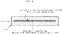
- FIG. 9 similarly to the above-described Example, a urethane elastomer with an adhesive and having a thickness of 40 ⁇ m was used as a base material, and silver-plated nylon fibers each having a length of 0.5 mm to 3 mm and a diameter of 17.6 ⁇ m were stuck in a saturated state to a wire width W to which the electrically-conductive fiber materials were attached.
- FIG. 10 indicates measured results in regard to change in resistance value with respect to stretch rate when changing W.
- the stretchable electrically-conductive circuits according to the present invention intersect with each other, in an intersection portion, opposing, attached electrically-conductive fiber materials function as opposing electrodes, and elastomer sheets present between the opposing electrodes function as electricity storage units (capacitors), so that the stretchable electrically-conductive circuits can be used as a stretchable capacitive pressure sensor.
- an elastomer sheet 1a in which an electrically-conductive fiber material attached layer 2a extends in a horizontal direction and an elastomer sheet 1b in which an electrically-conductive fiber material attached layer 2b extends in a perpendicular direction are overlapped and attached to each other, so that the elastomer sheets 1a and 1b present in an intersection portion 7 of the electrically-conductive fiber material attached layers 2a and 2b function as the capacitors which stores electrons.
- FIG. 12 illustrates measured results in regard to a change in capacitance with respect to an increase in pressure when the wire widths W of the electrically-conductive fiber material attached layers 2a and 2b intersecting with each other in the perpendicular direction were set to be from 2 mm to 20 mm. It is found that, the larger the wire widths W are set to be, the larger the capacitance increases till reaching high pressure.
- FIG. 13 illustrates measured results in regard to a change in capacitance with respect to an overlapping area when pressure was set to be 1 N (square) and 200 N (circle), the overlapping area of the electrically-conductive fiber material attached layers 2a and 2b is taken along an axis of the abscissas, and the capacitance is taken along an axis of the ordinate.
- the capacitance and the overlapping area are in a substantially direct proportional relation.
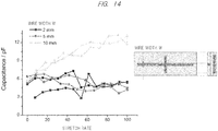
- FIG. 14 illustrates measured results in regard to a change in capacitance when the wire widths W were set to be 2 mm, 5 mm, and 10 mm and when stress in the horizontal direction was applied to the front surfaces of the elastomer sheets 1a and 1b, so that the elastomer sheets 1a and 1b were stretched.
- the capacitance with respect to a stretch rate is hardly changed.
- the elastomer sheets 1a and 1b contract and the capacitance increases due to the stretch, but the area of the overlapping portion also decreases along with the contraction, so that it can be considered that they offset each other.
- the stretchable capacitive pressure sensor of the present Example can accurately detect the pressure or load applied in the perpendicular direction by selecting the wire width W regardless of the stretch in the horizontal direction.
- FIG. 15 illustrates an example of widening an interelectrode gap by interposing, between the elastomer sheets 1a and 1b, elastomer sheets 1c and 1d without electrically-conductive fiber material attached layer and having a predetermined thickness.
- FIG. 16 illustrates a change in capacitance with respect to the elastomer sheets to be interposed when applying a pressure of 500 N to the stretchable electrically-conductive circuits.
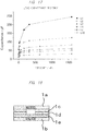
- FIG. 17 illustrates a change in capacitance with respect to a change in pressure and a change in load in a case of increasing the electrode gap due to the interposed elastomer sheets in order from L1 (first layer) to L10 (tenth layer).
- a small number of layers of the elastomer sheet can enhance sensitivity with respect to a small change in pressure and a small change in load.
- the layers of the elastomer sheet are increased, in a case where pressure and load are small, capacitance decreases in accordance with increase of the electrode gap, but an amount of contraction with respect to change in pressure of the interposed elastomer sheet increases, and accordingly, change in capacitance can be measured in a wide range.
- FIG. 18 illustrates an example in which the elastomer sheets 1c to 1e to be interposed are provided with an opening corresponding to a portion where the electrically-conductive fiber material attached layers 2a and 2b overlap.
- FIG. 19 illustrates measured results of a change in capacitance with respect to the pressure in a case of laminating the elastomer sheets from one layer with no opening (L1) to four layers with the opening (L5) sequentially.
- a second stretchable electrically-conductive circuit intersecting with the first stretchable electrically-conductive circuit is used as a stretchable capacitive pressure sensor, so that it is possible to measure pressure, load, and stretch simultaneously.
- an elastomer sheet 1a constituting the first stretchable electrically-conductive circuit has one electrically-conductive fiber material attached layer 2a formed therein in a horizontal direction
- the elastomer sheet 1b constituting the second stretchable electrically-conductive circuit 1b has five electrically-conductive fiber material attached layers 2b formed therein in a perpendicular direction.
- a resistance value of each of the electrically-conductive fiber material attached layer 2a disposed between both ends is measured at each of portions where the electrically-conductive fiber material attached layer 2a and the electrically-conductive fiber material attached layers 2b overlap, and accordingly, stretch can be measured similarly to Example 5.
- pressure and load can be measured.
- stretch, pressure, and load in the five portions can be measured independently and simultaneously.
- the elastomer sheet 1a constituting the first stretchable electrically-conductive circuit and the elastomer sheet 1b constituting the second stretchable electrically-conductive circuit are both rectangular having a size of 100 mm x 45 mm.
- the elastomer sheet 1a has one electrically-conductive fiber material attached layer 2a formed therein in the horizontal direction
- the elastomer sheet 1b has eight electrically-conductive fiber material attached layers 2b formed therein in the perpendicular direction
- overlapping portions are formed at eight points from C1 to C8.
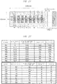
- FIG. 22 illustrates measured results of resistance values R1 to R8 among the eight electrically-conductive fiber material attached layers 2b when stretch is applied to a portion between C1 and C4 among the eight overlapping portions where capacitance elements are formed and when load is applied to the portions C3 and C7.
- FIG. 22 further illustrates measured results of capacitance in each of the eight overlapping portions C1 to C8 where the capacitance elements are formed.
- the measured results are indicated in an upper row, while the actual measured results of stretch rate and load are indicated in a lower row. Based on FIG. 23 , it is found that they are highly correlated.
- the stretchable electrically-conductive circuit can be expected to be widely used, for example, as an antenna or wire for RFID devices, a wire for a motion analysis sensor in sports science, a wearable heartbeat/electrocardiogram monitor, a wire in a robot movable portion, a wire for a finger sensor, and a wire for a bendable sensor attached to a finger, an elbow joint, and a knee joint.
- the stretchable electrically-conductive circuit can be used as a stretch amount sensor.
- the elastomer sheet is interposed between the electrically-conductive fiber material attached layers in such a way that the electrically-conductive fiber material attached layers are opposed to each other, and accordingly, the stretchable electrically-conductive circuit can also be used as a pressure sensor.
Landscapes
- Engineering & Computer Science (AREA)
- Microelectronics & Electronic Packaging (AREA)
- Manufacturing & Machinery (AREA)
- Power Engineering (AREA)
- Physics & Mathematics (AREA)
- General Physics & Mathematics (AREA)
- Laminated Bodies (AREA)
- Structure Of Printed Boards (AREA)
Abstract
Description
- The present invention relates to a stretchable electrically-conductive circuit having excellent stretchability and bendability and a method for manufacturing the same.
- Recently, demand for such a stretchable electrically-conductive circuit has been increased in various fields, for example, an antenna or a wire for RFID devices requiring flexibility, a wire for a motion analysis sensor in sports science, a wearable heartbeat/electrocardiogram monitor, a wire in a robot movable portion, and a wire for a finger sensor in order to transmit commands to a computer. Furthermore, the stretchable electrically-conductive circuit has been demanded as a wire for a bendable sensor attached to a finger, an elbow joint, and a knee joint in order to remotely control a robot.
-
Patent Document 1 discloses a method for manufacturing an electrically-conductive rubber having stretchability by dispersing ionic liquids and carbon nanotubes in rubber. -
Patent Document 2 discloses a method for manufacturing a stretchable circuit substrate by sticking a copper wire having a wavelike structure on an elastomer. -
Patent Document 3 discloses a method of providing a wire including urethane rubber and silver powder to a lower surface of an elastomer sheet made from ester urethane rubber. -
Patent Document 4 discloses a method of providing an antenna for a booster including electrically-conductive fibers to an antenna of an IC chip such that the antenna for a booster is disposed to face each other in a state in which the antenna of the IC chip does not adhere to the antenna for the booster. -
- Patent Document 1:
WO 2009-102077 A (Japanese Patent Application No. 2009-553493 - Patent Document 2:
Japanese Patent Application Laid-Open Publication No. 2013-187380 - Patent Document 3:
Japanese Patent Application Laid-Open Publication No. 2011-34822 - Patent Document 4:
Japanese Patent Application Laid-Open Publication No. 2013-206080 -
Patent Document 1 discloses a method for forming a stretchable electrical conductor by dispersing carbon nanotubes, metallic nanowires, and the like so as to achieve electrical conductivity. Although these materials are expensive, it is necessary to extremely enhance contents of these materials in order to obtain sufficient electrical conductivity. Accordingly, a final product becomes expensive, which prevents popularization of the stretchable electrical conductor in fields of sports science and medicine. - Meanwhile,
Patent Document 2 discloses that stretchability is realized by a structure of a metallic pattern itself such as a wavelike wire, and there are problems that a manufacturing process is complicated and a stretch rate is poor. -
Patent Document 3 discloses that silver powder is enclosed inside urethane rubber so as to manufacture a stretchable conducting wire individually, and there are problems that cost is high and flexibility is impaired. Also, a function as the conducting wire is impaired when an electrical contact among the silver powder is cut off in any positions. - As disclosed in
Patent Document 4, in a case of using electrically-conductive fibers, the electrically-conductive fibers themselves are expensive, and furthermore, it is necessary to cut out electrically-conductive fiber sheets when forming an antenna of various forms. Consequently, a large number of the electrically-conductive fiber sheets are wasted, which leads to a further cost increase and restriction on degree of freedom in bendable antenna forms. - Therefore, an object of the present invention is to provide a low-cost stretchable electrically-conductive circuit having excellent stretchability, bendability, durability, as well as used as a stretch sensor and capacitive pressure sensor, by adsorbing electrically-conductive fiber materials such as stretchable fibers, for example, nylon, whose surfaces are attached with silver by a vacuum evaporation to a front surface of a base material having both viscosity and stretchability, and to provide a manufacturing method therefor.
- In order to solve the above-described problems, a stretchable electrically-conductive circuit according to the present invention includes: an elastomer sheet having an adhesive layer corresponding to a wiring region with a predetermined pattern formed on a front surface of the elastomer sheet; and electrically-conductive fiber materials each having a predetermined diameter and a predetermined length and attached to the adhesive layer and coming in contact with each other along the wiring region so as to have mutual electrical continuity, and the electrically-conductive fiber materials relatively move maintaining the mutual electrical continuity so as to maintain the mutual electrical continuity in the wiring region when the elastomer sheet is stretched or bended.
- Also, a method for manufacturing a stretchable electrically-conductive circuit according to the present invention includes the steps of: forming an adhesive layer on a front surface of an elastomer sheet using a mask corresponding to a wiring region with a predetermined pattern; attaching electrically-conductive fiber materials on the adhesive layer; removing, among the electrically-conductive fiber materials, an electrically-conductive fiber material unable to be applied to the adhesive layer; and removing the mask after hardening the adhesive layer.
- According to the present invention, electrically-conductive fiber materials each having a predetermined diameter and a predetermined length are attached to a front surface of an elastomer sheet adhesive layer corresponding to a wiring region with a predetermined pattern, and electrically-conductive fiber materials relatively move maintaining mutual electrical continuity so as to maintain the electrical continuity in the wiring region when the elastomer sheet is stretched or bended. Therefore, it is possible to achieve a low-cost stretchable electrically-conductive circuit having excellent stretchability, bendability, and durability without impairing flexibility of the elastomer sheet.
- Furthermore, the stretchable electrically-conductive circuit can be used as a stretch amount sensor by making use of such an advantage that electrical continuity with respect to a stretch rate, that is, a characteristic of a change in resistance value can be variously adjusted by selecting fiber lengths and the like of the electrically-conductive fiber materials.
- Furthermore, an elastomer sheet is interposed between attached layers of the electrically-conductive fiber materials in such a way that the attached layers of the electrically-conductive fiber materials are opposed to each other, and accordingly, capacitance between opposing electrodes is changed in accordance with pressure and load applied on a front surface of the elastomer sheet, so that the stretchable electrically-conductive circuit can be used as a pressure sensor.
-
-
FIG. 1(a) is a schematic view illustrating an initial state of electrically-conductive fiber materials according to the present invention; -
FIG. 1(b) is a schematic view illustrating a bending state of electrically-conductive fiber materials according to the present invention; -
FIG. 1(c) is a schematic view illustrating a bending state of electrically-conductive fiber materials according to the present invention; -
FIG. 2 is a view illustrating a relation between a stretch of an elastomer sheet and an increase in resistance value; -
FIG. 3 is a view illustrating how to attach electrically-conductive fiber materials by a brush roller method; -
FIG. 4 is a view illustrating how to attach the electrically-conductive fiber materials by a spray method; -
FIG. 5 is a view illustrating a relation between a length of silver-coated fibers, a stretch of a stretchable elastomer sheet, and an increase in resistance; -
FIG. 6 is a view illustrating actual measured values of a stretch rate and a sheet resistance of Example 1; -
FIG. 7 is a view illustrating a stretchable electrically-conductive circuit of Example 4 to which a cable-like stretchable electrically-conductive circuit is applied; -
FIG. 8 is a view illustrating measured values of a change in resistance value with respect to a stretch rate of the cable-like stretchable electrically-conductive circuit according to Example 4; -
FIG. 9 is a view illustrating a stretchable electrically-conductive circuit of Example 5 used as a stretch amount detection sensor; -
FIG. 10 is a view illustrating measured values of a change in resistance value with respect to a stretch rate when changing a wire width W in Example 5; -
FIG. 11 is a view illustrating stretchable electrically-conductive circuits of Example 6 used as a capacitive pressure sensor; -
FIG. 12 is a view illustrating a change in capacitance with respect to pressure when changing the wire width W; -
FIG. 13 is a view illustrating a relation between capacitance and an area of an element formed in an intersection portion in Example 6; -
FIG. 14 is a view illustrating measured values of a change in capacitance with respect to a stretch in a horizontal direction; -
FIG. 15 is a view illustrating an example in which elastomer sheets are interposed as intermediate layers; -
FIG. 16 is a view illustrating a change in capacitance and a change in number of the elastomer sheets serving as the intermediate layers; -
FIG. 17 is a view illustrating a change in capacitance with respect to pressure when the number of the elastomer sheets serving as the intermediate layers is increased; -
FIG. 18 is a view illustrating a modification example in which an opening is provided in the elastomer sheets serving as the intermediate layers; -
FIG. 19 is a view illustrating a change in capacitance with respect to pressure when the number of the intermediate layers in which the opening is formed is increased; -
FIG. 20 illustrates Example 7 in which one electrically-conductive fiber attached layer formed on one elastomer sheet and five electrically-conductive fiber attached layers formed on the other elastomer sheet intersect at five points, where one elastomer sheet serves as a stretch detection sensor and the other serves as a pressure sensor; -
FIG. 21 is a view illustrating an example of measurement according to Example 7; -
FIG. 22 is a view illustrating actual measured values of resistance values and capacitance when a load is applied to the example of measurement; and -
FIG. 23 is a view illustrating a relation between measured values of resistance values and capacitance and actual values of stretch amount and pressure. - First, a fundamental principle of the present invention will be described.
-
FIG. 1(a) is a schematic view illustrating an initial state of electrically-conductive fiber materials, andFIG. 1(b) and FIG. 1(c) are schematic views illustrating a bending state of electrically-conductive fiber materials. - In the present invention, an adhesive layer is formed on an
elastomer sheet 1 including urethane elastomer and the like along a desired circuit wire. Electrically-conductive fiber materials 2 each having a predetermined length and a predetermined diameter are attached to the adhesive layer. - When the electrically-
conductive fiber materials 2 reach the adhesive layer, at least a part of a tip portion or a middle portion of the electrically-conductive fiber materials 2 is buried in the adhesive layer. When a front surface of the adhesive layer is slightly pressed with a roller or when the front surface is coated with a film and the like, exposed part falls over the front surface of the adhesive layer and intersects with each other to be electrically connected. Accordingly, as the initial state illustrated inFIG. 1(a) , electrical continuity is secured through the whole area between both ends of the circuit wire in a longitudinal direction. - Note that, in the drawings, closed circles indicate connecting points of the electrically-
conductive fiber materials 2 and arrows indicate flows of electric currents in which an upper left electrically-conductive fiber material 2 is regarded as a starting point. - When the
elastomer sheet 1 is stretched or bended, the respective electrically-conductive fiber materials 2 relatively move maintaining intersection with the other electrically-conductive fiber materials 2 on the front surface of the adhesive layer as astate 1 illustrated inFIG. 1(b) , so that electrical continuity securely can be maintained without affecting flexibility of theelastomer sheet 1. - However, when the
elastomer sheet 1 is extremely stretched as astate 2 illustrated inFIG. 1(c) , the electrical connection is cut off between partial electrically-conductive fiber materials 2. Furthermore, a length of the electrically-conductive fiber materials 2 electrically connecting to each other is increased, which leads to an increase in resistance value. - A relation between the stretch of the elastomer sheet and the increase in resistance value is illustrated in
FIG. 2 . - A lower straight line represents an ideal state in which all the electrical connections of the respective electrically-conductive fiber materials are maintained regardless of a stretch amount of the elastomer sheet. Basically, a resistance value increases in proportion to a distance between both ends of the electrically-conductive fiber materials accompanying the stretch of the elastomer sheet.
- In contrast, when the a stretch mount of the elastomer sheet reaches a degree of value, detachment between the electrically-conductive fiber materials occurs, an amount of the detachment drastically increases in accordance with the stretch, the elastomer sheet transits from the
state 1 to thestate 2, and along with this transition, the resistance value drastically increases. - Hereinafter, consideration is given to a quality, a length, a diameter of each electrically-conductive fiber material and a relation between an arrangement of the electrically-conductive fiber materials in the adhesive layer and a characteristic of increase in resistance as illustrated in
FIG. 2 . - As described above, since the electrically-conductive fiber materials relatively move maintaining intersection with the other electrically-conductive fiber materials on the front surface of the adhesive layer, it is preferable that a quality of the electrically-conductive fiber material has high flexibility in order to maintain electrical connection between the electrically-conductive fiber materials even when the elastomer sheet is largely stretched or bended.
- In a case where the elastomer sheet is expected to be bended largely, a silver-coated fiber in which a front surface of a nylon fiber is coated with silver can be considered as a preferable example.
- Furthermore, a fiber material obtained by polymerizing an electrically-conductive polypyrrole polymer to a front surface of a fiber and by integrating with a fiber of a base material also has a thin electrically-conductive polymer layer having a thickness of 0.01 to 0.05 µm on its front surface, which is therefore preferable as the electrically-conductive fiber material which does not impair characteristics of the fiber material.
- Conversely, in a case of mounting the elastomer sheet to a portion stretched or bended not so largely, a metal staple fiber obtained by cutting a fine wire of copper or aluminum to a predetermined length can be applied as the electrically-conductive fiber material.
- The longer the electrically-conductive fiber material, the longer the length from an intersection portion between adjacent electrically-conductive fiber materials can be secured. Therefore, even when the stretch amount of the elastomer sheet increases, the electrical connection between the adjacent electrically-conductive fiber materials is hardly cut off, so that increase in resistance value can be reduced.
- However, when the electrically-conductive fiber material is too long, a portion not coming in contact with the adhesive layer increases, which causes the electrically-conductive fiber material to be easily detached from the adhesive layer. Therefore, an optimum length is selected taking into consideration a bending rate of the elastomer sheet and the like.
- When the diameter of each electrically-conductive fiber material is enlarged, electric resistance per one material can be decreased, but rigidity increases, and accordingly, electrical contact between other adjacent electrically-conductive fiber materials cannot be conducted smoothly.
- As described later, in a case where a material in which fibers such as nylon are coated with a metal having excellent electrical conductivity such as silver is used as the electrically-conductive fiber material, electric resistance is determined based on a front surface area of the electrically-conductive fiber material. Therefore, it is not always possible to obtain a desired electric resistance with respect to a total amount of the attached electrically-conductive fiber material. Therefore, an optimum diameter is selected taking into consideration characteristics of the electrically-conductive fiber material to be used, a rate of change in electric resistance accompanying bending of the elastomer sheet.
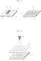
- When attaching the electrically-conductive fiber materials on the adhesive layer, a brush roller method or a spray method is applicable.
- In regard to the brush roller method, as illustrated in
FIG. 3 , on theelastomer sheet 1 having the adhesive layer on the front surface thereof, amask 4 corresponding to acircuit wire 3 is disposed, and after an adhesive is applied to form the adhesive layer, the electrically-conductive fiber materials 2 are then buried into the adhesive layer by arotation brush 5. As a result, the electrically-conductive fiber materials 2 can be oriented to some extent. Even when theelastomer sheet 1 is largely stretched in the longitudinal direction, it is possible to maintain electrical contact between the electrically-conductive fiber materials 2. - However, with respect to stretch of the
elastomer sheet 1 in a width direction, there is a possibility that electrically-conductive resistance is deteriorated due to a shortage of the electrically-conductive fiber materials 2 intersecting in the width direction on the front surface of the adhesive layer. - Note that, on the
elastomer sheet 1 in which a hardened adhesive layer is formed on the whole surface thereof, amask 4 composed of a material having high detachability may be disposed, the electrically-conductive fiber materials 2 may be buried in the adhesive layer with therotation brush 5, and then, themask 4 may be detached from the adhesive layer. - Meanwhile, in regard to the spray method, the electrically-
conductive fiber materials 2 are sprayed to the adhesive layer from above themask 4 corresponding to thecircuit wire 3 by aspray 6 with high pressure as illustrated inFIG. 4 . In this method, random arrangement can be obtained. - In either case, the electrically-
conductive fiber materials 2 are supplied and excessively attached to the adhesive layer until exceeding a saturated state where the electrically-conductive fiber materials 2 can be attached to the adhesive layer. Then, excess electrically-conductive fiber materials 2 are removed by compressed air to form a circuit wire. - Herein, in a case where silver-coated fibers (diameter of 17.6 µm) having nylon coated with silver are used as the electrically-conductive fiber materials and where the electrically-conductive circuit wire of the present invention is formed on an elastomer sheet having a sample size of 48 mm x 2 mm, each length of the silver-coated fibers and actual measured values of a change in resistance value accompanying the stretch are illustrated in
FIG. 5 . - Note that "sealing" in the drawing represents an aspect in which the silver-coated fibers attached to the adhesive layer are sealed with a similar elastomer sheet or a coated layer formed of a thin film and the like having flexibility equivalent to or more than the elastomer sheet and front surfaces of the silver-coated fibers attached to the adhesive layer is pressed.
- As for maximum stretch amounts, each graph represents [silver-coated fiber of 3.0 mm with sealing], [silver-coated fiber of 0.5 mm with sealing], [3.0 mm, no sealing], [mixture of silver-coated fibers of 0.5 mm and of 3.0 mm, no sealing], and [silver-coated fiber 0.5 mm, no sealing] in the order from one having smaller increase in resistance value.
- As seen from the actual measured results, in a case of sealing an upper surface with the silver-coated fibers each having a diameter of 17.6 µm and a length of 3 mm as the electrically-conductive fiber materials, the resistance value is hardly increased even at the maximum stretch amount of 30 mm. This represents that the silver-coated fibers have a sufficient length in the upper surface of the adhesive layer even when stretched to the maximum stretch amount. In addition, this represents that the electrical connection between the silver-coated fibers is mostly maintained since the upper surface is pressed by the elastomer sheet or thin film.
- In contrast, even in a case of using short silver-coated fibers each having a diameter of 17.6 µm and a length of 0.6 mm, when the upper surface is pressed by the elastomer sheet or thin film, it is possible to suppress increase in resistance value to a minimum as long as the stretch amount is up to 25 mm.
- Coating the upper surface with use of the elastomer sheet or thin film causes a cost increase or deterioration of flexibility. However, a length and a combination of the silver-coated fibers, and presence or absence of the upper surface coated layer may be selected in accordance with uses, for example, a degree of stretch generated when the elastomer sheet or thin film is used.
- Meanwhile, for example, it is found that, in a case of using [silver-coated fiber of 0.5 mm, no sealing], increase in resistance with respect to the stretch is large, and except for a case of using [silver-coated fiber of 3.0 mm, with sealing], increase in resistance becomes large with respect to the stretch on a one-to-one relation.
- By taking advantage of this characteristic, it is possible to measure the stretch amount based on change in resistance value by using a stretchable electrically-conductive sheet using the electrically-
conductive fiber materials 2 according to the present invention. - Furthermore, by laminating stretchable electrically-conductive sheets, it is possible to allow an elastomer sheet located between the electrically-conductive fiber materials to function as a capacitor, and it is also possible to use as a pressure sensor by measuring capacitance accompanying a change in gap between the electrically-conductive fiber materials in accordance with a front surface pressure of the stretchable electrically-conductive sheet.
- Hereinafter, specific examples will be described with reference to the drawings.
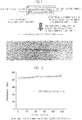
- An adhesive layer was applied to the whole surface of an elastomer sheet (for example, a urethane elastomer sheet having a size of 3 cm x 8 cm and a thickness of 1 mm) having predetermined flexibility. With viscosity appearing on the adhesive layer to some extent, silver-plated nylon fibers each having a length of 0.5 mm to 3 mm and a diameter of 17.6 µm were attached to the adhesive layer as the electrically-conductive fiber materials by the brush roller method. Sheet resistance of the stretchable electrically-conductive sheet was measured by a resistance meter. Actual measured results are indicated in
FIG. 6 . - There was a small change in sheet resistance up to a 250% stretch rate, which indicated a preferable characteristic.
- Silver-plated nylon fibers (a fiber length of 0.3 mm to 3 mm, a fiber diameter of 17.6 µm) were adsorbed to an adhesive layer of an elastomer adhesive sheet (a size of 3 cm x 8 cm, a thickness of 1 mm) by the brush roller spray method. The electrically-conductive sheet was brought into contact with an LED lighting circuit wire, and luminance of the LED was visually observed when a stretch rate was approximately 100%. Comparing to a case when the stretch rate was 0%, change in luminance was not observed.
- An antenna pattern for UHF-RFID was formed by forming a mask in which PET was cut on an adhesive layer of an elastomer adhesive sheet (a size of 3 cm x 9 cm, a thickness of 1 mm) and by adsorbing silver-plated nylon fibers (a fiber length of 0.3 mm to 3 mm, a fiber diameter of 17.6 µm) to the mask by the brush roller method.
- The antenna pattern was mounted with an IC chip for RFID conforming to EPC global gen2 to form a stretchable RFID tag. Attaching the stretchable RFID tag to clothing, a readout experiment was carried out by an RFID readout device (BHT-604QUWB made by DENSO WAVE Inc., at an output of 10 mW).
- The ID could be read out within a communication distance of approximately 3 cm. Even when a stretch rate reached approximately 100%, the communication distance could be maintained within approximately 2.5 cm.
- Note that, in Examples 1 to 3, there were no big differences among the experimental results even in a case of sticking the silver-plated nylon fibers by the spray method.
- As illustrated in
FIG. 7 , in regard to an elastomer sheet (for example, a urethane elastomer sheet having a size of 20 cm x 10 cm, a thickness of 40 µm) having predetermined flexibility and including an adhesive layer applied to one surface thereof, with viscosity to some extent appearing on the adhesive layer of one surface of the elastomer sheet, silver-plated nylon fibers each having a length of 0.5 mm to 3 mm and a diameter of 17.6 µm were attached in a width of 5 cm and a length of 15 cm in a length direction of the elastomer sheet to the elastomer sheet by the brush roller method. - In the present Example, a width of the elastomer sheet was made larger than a width of a layer to which the silver-plated nylon fibers were stuck (hereinafter, referred to as a "wire width W"), and after being stuck, the elastomer sheet was rolled so as to make a cable-like stretchable wire of which a cross-section was in a circular shape.
-
FIG. 8 indicates results obtained by measuring a change in resistance with respect to the stretch of the stretchable wire by the resistance meter. It was possible to obtain an excellent cable-like stretchable wire in which a resistance value was hardly changed even with respect to a 100% stretch rate (double stretch). - Examples 1 to 4 relate to a stretchable electrically-conductive sheet or a cable-like stretchable wire in which change in resistance value is restrained as much as possible with respect to stretch, and Example 5 relates to a stretch amount detection sensor in which a resistance value with respect to a stretch amount is used positively.
- In
FIG. 9 , similarly to the above-described Example, a urethane elastomer with an adhesive and having a thickness of 40 µm was used as a base material, and silver-plated nylon fibers each having a length of 0.5 mm to 3 mm and a diameter of 17.6 µm were stuck in a saturated state to a wire width W to which the electrically-conductive fiber materials were attached. -
FIG. 10 indicates measured results in regard to change in resistance value with respect to stretch rate when changing W. - In regard to a wire width of 5 mm to 20 mm, there was a small change in resistance value with respect to the stretch rate, which indicated an excellent characteristic as the stretchable electrically-conductive circuit. However, when the wire width was 2 mm, it can be confirmed that the resistance value with respect to the stretch rate increased substantially linearly. This phenomenon is also similar in a case where fiber lengths of the respective silver-plated nylon fibers were shortened.
- Taking advantage of such a characteristic, by variably selecting a length, a diameter, and a wire width W of each silver-plated nylon fiber, it is possible to use as the stretch amount sensor if a resistance value and a stretch amount are mapped in advance.
- In the present Example, the stretchable electrically-conductive circuits according to the present invention intersect with each other, in an intersection portion, opposing, attached electrically-conductive fiber materials function as opposing electrodes, and elastomer sheets present between the opposing electrodes function as electricity storage units (capacitors), so that the stretchable electrically-conductive circuits can be used as a stretchable capacitive pressure sensor.
- Specifically, as illustrated in
FIG. 11 , anelastomer sheet 1a in which an electrically-conductive fiber material attachedlayer 2a extends in a horizontal direction and anelastomer sheet 1b in which an electrically-conductive fiber material attachedlayer 2b extends in a perpendicular direction are overlapped and attached to each other, so that theelastomer sheets intersection portion 7 of the electrically-conductive fiber material attachedlayers - When pressure or load in the perpendicular direction is applied to front surfaces of the
elastomer sheets elastomer sheets intersection portion 7, and a distance between the electrically-conductive fiber material attachedlayers -
FIG. 12 illustrates measured results in regard to a change in capacitance with respect to an increase in pressure when the wire widths W of the electrically-conductive fiber material attachedlayers -
FIG. 13 illustrates measured results in regard to a change in capacitance with respect to an overlapping area when pressure was set to be 1 N (square) and 200 N (circle), the overlapping area of the electrically-conductive fiber material attachedlayers layers - Meanwhile,
FIG. 14 illustrates measured results in regard to a change in capacitance when the wire widths W were set to be 2 mm, 5 mm, and 10 mm and when stress in the horizontal direction was applied to the front surfaces of theelastomer sheets elastomer sheets - Specifically, when the wire widths W were set to be 2 mm and 5 mm, the capacitance with respect to a stretch rate is hardly changed. The
elastomer sheets - Therefore, the stretchable capacitive pressure sensor of the present Example can accurately detect the pressure or load applied in the perpendicular direction by selecting the wire width W regardless of the stretch in the horizontal direction.
- In the present Example, various modifications are applicable.
-
FIG. 15 illustrates an example of widening an interelectrode gap by interposing, between theelastomer sheets elastomer sheets 1c and 1d without electrically-conductive fiber material attached layer and having a predetermined thickness. -
FIG. 16 illustrates a change in capacitance with respect to the elastomer sheets to be interposed when applying a pressure of 500 N to the stretchable electrically-conductive circuits. -
FIG. 17 illustrates a change in capacitance with respect to a change in pressure and a change in load in a case of increasing the electrode gap due to the interposed elastomer sheets in order from L1 (first layer) to L10 (tenth layer). - In such manners, a small number of layers of the elastomer sheet can enhance sensitivity with respect to a small change in pressure and a small change in load. In contrast, when the layers of the elastomer sheet are increased, in a case where pressure and load are small, capacitance decreases in accordance with increase of the electrode gap, but an amount of contraction with respect to change in pressure of the interposed elastomer sheet increases, and accordingly, change in capacitance can be measured in a wide range.
-
FIG. 18 illustrates an example in which the elastomer sheets 1c to 1e to be interposed are provided with an opening corresponding to a portion where the electrically-conductive fiber material attachedlayers FIG. 19 illustrates measured results of a change in capacitance with respect to the pressure in a case of laminating the elastomer sheets from one layer with no opening (L1) to four layers with the opening (L5) sequentially. - Although L2 to which one layer of the elastomer sheet with the opening was added indicates the highest sensitivity, by increasing the number of the elastomer sheets with the opening sequentially, a linear characteristic becomes favorable, and accordingly, it is found that it is possible to enhance accuracy and also to measure in ranges of much higher pressure and load.
- In the present Example, with respect to a first stretchable electrically-conductive circuit in which the stretchable electrically-conductive circuit according to the present invention is used as the stretch detection sensor, a second stretchable electrically-conductive circuit intersecting with the first stretchable electrically-conductive circuit is used as a stretchable capacitive pressure sensor, so that it is possible to measure pressure, load, and stretch simultaneously.
- As illustrated in
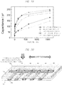
FIG. 20 , anelastomer sheet 1a constituting the first stretchable electrically-conductive circuit has one electrically-conductive fiber material attachedlayer 2a formed therein in a horizontal direction, and theelastomer sheet 1b constituting the second stretchable electrically-conductive circuit 1b has five electrically-conductive fiber material attachedlayers 2b formed therein in a perpendicular direction. Herein, a resistance value of each of the electrically-conductive fiber material attachedlayer 2a disposed between both ends is measured at each of portions where the electrically-conductive fiber material attachedlayer 2a and the electrically-conductive fiber material attachedlayers 2b overlap, and accordingly, stretch can be measured similarly to Example 5. Furthermore, by measuring capacitance between the electrically-conductive fiber material attachedlayer 2a and the electrically-conductive fiber material attachedlayers 2b at those portions, pressure and load can be measured. - As described above, since stretch has little influence on a measured value of pressure, in an example in
FIG. 20 , stretch, pressure, and load in the five portions can be measured independently and simultaneously. - The actual measured results are illustrated in
FIG. 21 and FIG. 22 . - In the present Example, as illustrated in
FIG. 21 , theelastomer sheet 1a constituting the first stretchable electrically-conductive circuit and theelastomer sheet 1b constituting the second stretchable electrically-conductive circuit are both rectangular having a size of 100 mm x 45 mm. Theelastomer sheet 1a has one electrically-conductive fiber material attachedlayer 2a formed therein in the horizontal direction, theelastomer sheet 1b has eight electrically-conductive fiber material attachedlayers 2b formed therein in the perpendicular direction, and overlapping portions are formed at eight points from C1 to C8. -
FIG. 22 illustrates measured results of resistance values R1 to R8 among the eight electrically-conductive fiber material attachedlayers 2b when stretch is applied to a portion between C1 and C4 among the eight overlapping portions where capacitance elements are formed and when load is applied to the portions C3 and C7.FIG. 22 further illustrates measured results of capacitance in each of the eight overlapping portions C1 to C8 where the capacitance elements are formed. - In
FIG. 23 , the measured results are indicated in an upper row, while the actual measured results of stretch rate and load are indicated in a lower row. Based onFIG. 23 , it is found that they are highly correlated. - Consequently, by mapping a relation among resistance value, stretch, capacitance, pressure, and load per combination of the first and the second stretchable electrically-conductive circuits, it is possible to accurately measure the relation among stretch, pressure, and load per overlapping portion. Accordingly, for example, when developing sports wears, a relation between a degree of stretch in a specific part and a load applied to a skin is measured, so that an optimum design can be achieved.
- As described above, according to the present invention, by simply attaching electrically-conductive fiber materials each having a predetermined diameter and a predetermined length to an adhesive layer of an elastomer sheet, it is possible to produce a low-cost stretchable electrically-conductive circuit having excellent stretchability, bendability, and durability without impairing flexibility of the elastomer sheet, and further, mass production of such a stretchable electrically-conductive circuit can be achieved. Therefore, the stretchable electrically-conductive circuit can be expected to be widely used, for example, as an antenna or wire for RFID devices, a wire for a motion analysis sensor in sports science, a wearable heartbeat/electrocardiogram monitor, a wire in a robot movable portion, a wire for a finger sensor, and a wire for a bendable sensor attached to a finger, an elbow joint, and a knee joint.
- Further, by selecting the fiber length and the like of the electrically-conductive fiber material, the stretchable electrically-conductive circuit can be used as a stretch amount sensor. Alternatively, the elastomer sheet is interposed between the electrically-conductive fiber material attached layers in such a way that the electrically-conductive fiber material attached layers are opposed to each other, and accordingly, the stretchable electrically-conductive circuit can also be used as a pressure sensor.
-
- 1:
- Elastomer sheet
- 2:
- Electrically-conductive fiber material
- 3:
- Circuit wire
- 4:
- Mask
- 5:
- Brush roller
- 6:
- Spray
Claims (12)
- A stretchable electrically-conductive circuit, comprising:an elastomer sheet having an adhesive layer corresponding to a wiring region with a predetermined pattern formed on a front surface of the elastomer sheet; andelectrically-conductive fiber materials each having a predetermined diameter and a predetermined length and attached to the adhesive layer and coming in contact with each other along the wiring region so as to have mutual electrical continuity,wherein the electrically-conductive fiber materials relatively move maintaining the mutual electrical continuity so as to maintain the mutual electrical continuity in the wiring region when the elastomer sheet is stretched or bended.
- The stretchable electrically-conductive circuit according to claim 1, wherein a front surface of each of the electrically-conductive fiber materials attached to the adhesive layer is sealed with the elastomer sheet or a coated layer formed of a thin film having higher flexibility than the elastomer sheet.
- The stretchable electrically-conductive circuit according to claim 1, wherein both surfaces of the elastomer sheet are configured to be adhesive layers and the elastomer sheet is rolled such that the electrically-conductive fiber material attached to one of the adhesive layers comes inside so as to form a conductive wire-like shape.
- The stretchable electrically-conductive circuit according to claim 2, wherein a fiber length of each fiber of the electrically-conductive fiber materials or a wire width of the electrically-conductive fiber materials to be attached is selected to increase the electrically-conductive fiber materials to be detached electrically in accordance with a stretch rate and to increase electric resistance when the elastomer sheet is stretched or bended, so that the stretchable electrically-conductive circuit functions as a stretch amount detection sensor detecting stretch amount.
- The stretchable electrically-conductive circuit according to claims 1 or 4, wherein the electrically-conductive fiber materials attached to two elastomer sheets intersect with each other, and attached layers of the electrically-conductive fiber materials in an intersection portion function as opposing electrodes and an elastomer sheet disposed between the opposing electrodes functions as a capacitor, and capacitance between the opposing electrodes is changed in accordance with a stretch of the elastomer sheet between the electrodes due to pressure and load applied in a perpendicular direction, so that the stretchable electrically-conductive circuit functions as a pressure sensor.
- The stretchable electrically-conductive circuit according to claim 5, wherein elastomer sheets in which the electrically-conductive fiber materials are not attached are laminated in the intersection portion.
- The stretchable electrically-conductive circuit according to claim 6, wherein an opening is provided in a lower portion of the intersection portion of at least one layer of the elastomer sheets in which the electrically-conductive fiber materials are not attached.
- The stretchable electrically-conductive circuit according to claim 5, wherein a plurality of rows of the attached layers of the electrically-conductive fiber materials are formed on one of the two elastomer sheets, and the intersection portions are formed at a plurality of portions in a longitudinal direction with respect to the attached layer of the electrically-conductive fiber materials formed in the other elastomer sheet.
- The stretchable electrically-conductive circuit according to claim 5, wherein one of the two elastomer sheets functions as a stretch amount detection sensor and the intersection portion functions as a pressure sensor.
- A method for manufacturing a stretchable electrically-conductive circuit, comprising the steps of:forming an adhesive layer on a front surface of an elastomer sheet using a mask corresponding to a wiring region with a predetermined pattern;attaching electrically-conductive fiber materials on the adhesive layer;removing, among the electrically-conductive fiber materials, an electrically-conductive fiber material unable to be applied to the adhesive layer; andremoving the mask after hardening the adhesive layer.
- The method for manufacturing a stretchable electrically-conductive circuit according to claim 10, wherein the electrically-conductive fiber materials are attached to the adhesive layer by a brush roller method.
- The method for manufacturing a stretchable electrically-conductive circuit according to claim 11, wherein the electrically-conductive fiber materials are attached to the adhesive layer by a spray method.
Applications Claiming Priority (3)
| Application Number | Priority Date | Filing Date | Title |
|---|---|---|---|
| JP2014102087 | 2014-05-16 | ||
| JP2014252330 | 2014-12-12 | ||
| PCT/JP2015/063943 WO2015174505A1 (en) | 2014-05-16 | 2015-05-14 | Stretchable electrically-conductive circuit and manufacturing method therefor |
Publications (4)
| Publication Number | Publication Date |
|---|---|
| EP3145283A1 true EP3145283A1 (en) | 2017-03-22 |
| EP3145283A4 EP3145283A4 (en) | 2018-02-28 |
| EP3145283C0 EP3145283C0 (en) | 2024-10-30 |
| EP3145283B1 EP3145283B1 (en) | 2024-10-30 |
Family
ID=54480041
Family Applications (1)
| Application Number | Title | Priority Date | Filing Date |
|---|---|---|---|
| EP15793610.5A Active EP3145283B1 (en) | 2014-05-16 | 2015-05-14 | Stretchable electrically-conductive circuit and manufacturing method therefor |
Country Status (5)
| Country | Link |
|---|---|
| US (1) | US10386248B2 (en) |
| EP (1) | EP3145283B1 (en) |
| JP (1) | JP6377147B2 (en) |
| KR (1) | KR101985065B1 (en) |
| WO (1) | WO2015174505A1 (en) |
Cited By (3)
| Publication number | Priority date | Publication date | Assignee | Title |
|---|---|---|---|---|
| WO2018085258A1 (en) * | 2016-11-07 | 2018-05-11 | E. I. Du Pont De Nemours And Company | Articles and substrates providing improved performance of printable electronics |
| RU2719733C1 (en) * | 2018-12-26 | 2020-04-22 | Автономная некоммерческая образовательная организация высшего образования «Сколковский институт науки и технологий» (Сколковский институт науки и технологий) | Elastic electric circuit and method of its manufacturing |
| CN115916527A (en) * | 2020-10-07 | 2023-04-04 | Nok株式会社 | Conductive rubber cloth |
Families Citing this family (14)
| Publication number | Priority date | Publication date | Assignee | Title |
|---|---|---|---|---|
| JP6829365B2 (en) * | 2017-01-12 | 2021-02-10 | 国立研究開発法人産業技術総合研究所 | Pressure sensors, pressure sensor manufacturing methods, bed devices and automotive seats |
| WO2018161099A1 (en) * | 2017-02-28 | 2018-09-07 | Detnet South Africa (Pty) Ltd | Stretchable detonator connection cable |
| JP2019032733A (en) * | 2017-08-09 | 2019-02-28 | 日本メクトロン株式会社 | Affixed tag, tag system |
| JP7147767B2 (en) * | 2017-08-24 | 2022-10-05 | 東洋紡株式会社 | Conductive pastes, stretchable conductors and electronic components using them, clothing-type electronic devices |
| JP7161738B2 (en) * | 2018-02-08 | 2022-10-27 | ナミックス株式会社 | Conductive paste, cured product, conductive pattern, clothes and stretchable paste |
| CN110403592B (en) * | 2018-04-28 | 2022-03-29 | 五邑大学 | Wrist strap type heart rate meter |
| CN110403589B (en) * | 2018-04-28 | 2022-04-01 | 五邑大学 | Disposable heart rate plaster |
| KR102678182B1 (en) * | 2018-11-16 | 2024-06-26 | 다이니폰 인사츠 가부시키가이샤 | Wiring board and manufacturing method of wiring board |
| JP7249512B2 (en) * | 2018-11-30 | 2023-03-31 | 大日本印刷株式会社 | Wiring board and method for manufacturing wiring board |
| KR102172366B1 (en) * | 2019-01-31 | 2020-10-30 | 포항공과대학교 산학협력단 | Microfibril network composite flexible substrate, composite flexible electrode comprising same and method of preparing same |
| JP7323613B2 (en) * | 2019-06-27 | 2023-08-08 | 株式会社巴川製紙所 | flexible wire |
| JP7386445B2 (en) * | 2019-08-27 | 2023-11-27 | パナソニックIpマネジメント株式会社 | load sensor |
| KR102256074B1 (en) | 2020-05-21 | 2021-05-26 | (주)케이디엔에이 | Stretchable near infrared ray light emitting diode band for smart healthcare |
| CN113995404B (en) * | 2021-10-29 | 2023-05-05 | 华中科技大学 | Amphibious capacitive flexible sensing unit and system for muscle deformation measurement |
Family Cites Families (31)
| Publication number | Priority date | Publication date | Assignee | Title |
|---|---|---|---|---|
| JPS53133151U (en) * | 1977-03-29 | 1978-10-21 | ||
| JPS60139845A (en) * | 1983-12-28 | 1985-07-24 | ジェイエスアール株式会社 | Pressure sensitive conductive fabric |
| JPS61201045A (en) * | 1985-03-04 | 1986-09-05 | 旭化成株式会社 | Deformed conductive knitted cloth |
| JPS6276602A (en) * | 1985-09-30 | 1987-04-08 | 旭化成株式会社 | Elongated conductive cloth piece |
| JPS62163903A (en) * | 1986-01-16 | 1987-07-20 | Asahi Chem Ind Co Ltd | Extending conductive element of insulating object to be inspected |
| JPS62200701A (en) * | 1986-02-28 | 1987-09-04 | 旭化成株式会社 | Deformed conductive knitting |
| JPS62200204A (en) * | 1986-02-28 | 1987-09-03 | Asahi Chem Ind Co Ltd | Elongating conductive element with fixing means having adjusting mechanism |
| JPS62200203A (en) * | 1986-02-28 | 1987-09-03 | Asahi Chem Ind Co Ltd | Extensible conductive element with fixing means |
| JPH03179794A (en) | 1989-10-30 | 1991-08-05 | Tokuyama Soda Co Ltd | Manufacture of conductive printed board |
| EP1105705B1 (en) * | 1998-08-20 | 2004-10-13 | IEE INTERNATIONAL ELECTRONICS & ENGINEERING S.A. | Flat electrode for capacitive recognition systems |
| JP2000071418A (en) | 1998-08-28 | 2000-03-07 | Canon Inc | Screen printing method and apparatus |
| JP2001047728A (en) | 1999-08-05 | 2001-02-20 | Ricoh Microelectronics Co Ltd | Method and apparatus for forming pattern, method for forming bump electrode, method for forming wiring pattern, method for forming spacer for liquid crystal display unit, method for forming spacer for touch panel and method for forming barrier for plasma display panel |
| JP2003266599A (en) * | 2002-03-19 | 2003-09-24 | Teijin Ltd | Surface conductive cloth with bending resistance |
| JP2006153471A (en) | 2004-11-25 | 2006-06-15 | Hitachi Cable Ltd | Pressure sensor |
| EP1742013A1 (en) * | 2005-07-06 | 2007-01-10 | Nederlandse Organisatie voor Toegepast-Natuuurwetenschappelijk Onderzoek TNO | System for measuring length and/or shape variations of an object |
| JP2008108583A (en) | 2006-10-25 | 2008-05-08 | Sumitomo Precision Prod Co Ltd | Conductive wire, conductive coil and conductive wire manufacturing method |
| JP2009141129A (en) | 2007-12-06 | 2009-06-25 | Sumitomo Electric Printed Circuit Inc | Flexible printed wiring board and method of manufacturing the same |
| JPWO2009102077A1 (en) | 2008-02-11 | 2011-06-16 | 国立大学法人 東京大学 | Carbon nanotube rubber composition, wiring, conductive paste, electronic circuit and method for producing the same |
| US8191433B2 (en) * | 2008-05-19 | 2012-06-05 | The Hong Kong Polytechnic University | Method for manufacturing fabric strain sensors |
| JP5256143B2 (en) | 2009-08-03 | 2013-08-07 | 東海ゴム工業株式会社 | Wiring body connection structure and manufacturing method thereof |
| US8880358B2 (en) * | 2010-04-16 | 2014-11-04 | Thomas J. Cunningham | Sensing device |
| JP2012168064A (en) | 2011-02-15 | 2012-09-06 | Tokai Rubber Ind Ltd | External force measurement apparatus and cushion body with the same |
| JP2012220315A (en) * | 2011-04-07 | 2012-11-12 | Seiko Epson Corp | Pressure detection device |
| US20140035603A1 (en) * | 2012-08-03 | 2014-02-06 | Xerox Corporation | Printed Stretch Sensor |
| DE102012103856B4 (en) * | 2012-02-16 | 2016-09-29 | Peter Seitz | Textile pressure sensor |
| JP2013187380A (en) | 2012-03-08 | 2013-09-19 | Nippon Mektron Ltd | Elastic flexible circuit board and manufacturing method of the same |
| JP5952609B2 (en) | 2012-03-28 | 2016-07-13 | トッパン・フォームズ株式会社 | Non-contact data transmitter / receiver |
| JP2014077952A (en) | 2012-10-12 | 2014-05-01 | Brother Ind Ltd | Brush roller for image forming apparatus and manufacturing method of the same, brush roller for development, and developing device |
| US9322121B2 (en) * | 2013-02-28 | 2016-04-26 | Regents Of The University Of Minnesota | Stitched stretch sensor |
| JP6377241B2 (en) * | 2015-02-20 | 2018-08-22 | 国立研究開発法人産業技術総合研究所 | Highly stretchable wiring, manufacturing method thereof, manufacturing apparatus |
| JP6666806B2 (en) * | 2016-07-14 | 2020-03-18 | トクセン工業株式会社 | Stretchable wiring sheet, manufacturing method thereof, and stretchable touch sensor sheet |
-
2015
- 2015-05-14 US US15/311,659 patent/US10386248B2/en active Active
- 2015-05-14 EP EP15793610.5A patent/EP3145283B1/en active Active
- 2015-05-14 JP JP2016519306A patent/JP6377147B2/en not_active Expired - Fee Related
- 2015-05-14 WO PCT/JP2015/063943 patent/WO2015174505A1/en not_active Ceased
- 2015-05-14 KR KR1020167032895A patent/KR101985065B1/en not_active Expired - Fee Related
Cited By (4)
| Publication number | Priority date | Publication date | Assignee | Title |
|---|---|---|---|---|
| WO2018085258A1 (en) * | 2016-11-07 | 2018-05-11 | E. I. Du Pont De Nemours And Company | Articles and substrates providing improved performance of printable electronics |
| US10827610B2 (en) | 2016-11-07 | 2020-11-03 | E I Du Pont De Nemours And Company | Articles and substrates providing improved performance of printable electronics |
| RU2719733C1 (en) * | 2018-12-26 | 2020-04-22 | Автономная некоммерческая образовательная организация высшего образования «Сколковский институт науки и технологий» (Сколковский институт науки и технологий) | Elastic electric circuit and method of its manufacturing |
| CN115916527A (en) * | 2020-10-07 | 2023-04-04 | Nok株式会社 | Conductive rubber cloth |
Also Published As
| Publication number | Publication date |
|---|---|
| KR20160147921A (en) | 2016-12-23 |
| WO2015174505A1 (en) | 2015-11-19 |
| US10386248B2 (en) | 2019-08-20 |
| KR101985065B1 (en) | 2019-05-31 |
| EP3145283A4 (en) | 2018-02-28 |
| EP3145283C0 (en) | 2024-10-30 |
| JPWO2015174505A1 (en) | 2017-04-20 |
| US20170153152A1 (en) | 2017-06-01 |
| EP3145283B1 (en) | 2024-10-30 |
| JP6377147B2 (en) | 2018-08-22 |
Similar Documents
| Publication | Publication Date | Title |
|---|---|---|
| EP3145283B1 (en) | Stretchable electrically-conductive circuit and manufacturing method therefor | |
| US11954296B2 (en) | Flexible capacitive tactile sensor and method for manufacturing same and tactile sensing system | |
| CN109781315B (en) | a tactile sensor | |
| US9945739B2 (en) | Flexible pressure sensor using amorphous metal and flexible bimodal sensor for simultaneously sensing pressure and temperature | |
| Khan et al. | Graphene tribotronics for electronic skin and touch screen applications | |
| US20150282294A1 (en) | Elastic flexible substrate and manufacturing method thereof | |
| EP3073236B1 (en) | Pressure sensor | |
| US11740141B2 (en) | Pressure-sensitive element | |
| WO2019014243A1 (en) | CAPACITIVE AND TOUCH SENSORS AND METHODS OF DETECTION THEREOF | |
| CN106441073A (en) | Dielectric flexible sensor for big deformation and touch pressure measurement | |
| Gillan et al. | Advances in design and manufacture of stretchable electronics | |
| CN206291983U (en) | A kind of electronic skin for touch detection | |
| US20180033520A1 (en) | Highly stretchable wiring, and method and device for producing the same | |
| CN105066863A (en) | Displacement sensor based on electroactive elastomer polymer | |
| Lee et al. | Ultraflexible vertical Corbino organic electrochemical transistors for epidermal signal monitoring | |
| CN114674465A (en) | Flexible material-based capacitive pressure sensor and manufacturing method thereof | |
| US10393599B2 (en) | Deformable apparatus and method | |
| CN109341909A (en) | A multifunctional flexible stress sensor | |
| Zuk | Capacitive sensors realized on flexible substrates | |
| JP2021081341A (en) | Detection circuit and load detector | |
| Panahi et al. | Condition monitoring system: a flexible hybrid electronics approach for sealed container applications | |
| JP7245995B2 (en) | Detection circuit and load detection device | |
| CN118067159B (en) | Curved surface segmented flexible sensor and manufacturing method of sensitive layer | |
| Chou et al. | Tactile sensor based on capacitive structure | |
| KR102549922B1 (en) | Self-powered stretchable ion gel sensor and manufacturing method thereof |
Legal Events
| Date | Code | Title | Description |
|---|---|---|---|
| STAA | Information on the status of an ep patent application or granted ep patent |
Free format text: STATUS: THE INTERNATIONAL PUBLICATION HAS BEEN MADE |
|
| PUAI | Public reference made under article 153(3) epc to a published international application that has entered the european phase |
Free format text: ORIGINAL CODE: 0009012 |
|
| STAA | Information on the status of an ep patent application or granted ep patent |
Free format text: STATUS: REQUEST FOR EXAMINATION WAS MADE |
|
| 17P | Request for examination filed |
Effective date: 20161215 |
|
| AK | Designated contracting states |
Kind code of ref document: A1 Designated state(s): AL AT BE BG CH CY CZ DE DK EE ES FI FR GB GR HR HU IE IS IT LI LT LU LV MC MK MT NL NO PL PT RO RS SE SI SK SM TR |
|
| AX | Request for extension of the european patent |
Extension state: BA ME |
|
| DAV | Request for validation of the european patent (deleted) | ||
| DAX | Request for extension of the european patent (deleted) | ||
| A4 | Supplementary search report drawn up and despatched |
Effective date: 20180130 |
|
| RIC1 | Information provided on ipc code assigned before grant |
Ipc: H01B 13/00 20060101ALI20180124BHEP Ipc: H01B 5/02 20060101ALI20180124BHEP Ipc: H01B 5/14 20060101ALI20180124BHEP Ipc: B32B 25/10 20060101ALI20180124BHEP Ipc: H01B 5/00 20060101ALI20180124BHEP Ipc: H01R 11/01 20060101ALI20180124BHEP Ipc: H05K 1/09 20060101ALI20180124BHEP Ipc: H05K 1/03 20060101ALI20180124BHEP Ipc: H05K 3/10 20060101ALI20180124BHEP Ipc: H01B 7/06 20060101ALI20180124BHEP Ipc: H05K 3/14 20060101ALI20180124BHEP Ipc: H05K 1/02 20060101AFI20180124BHEP |
|
| STAA | Information on the status of an ep patent application or granted ep patent |
Free format text: STATUS: EXAMINATION IS IN PROGRESS |
|
| 17Q | First examination report despatched |
Effective date: 20180907 |
|
| GRAP | Despatch of communication of intention to grant a patent |
Free format text: ORIGINAL CODE: EPIDOSNIGR1 |
|
| STAA | Information on the status of an ep patent application or granted ep patent |
Free format text: STATUS: GRANT OF PATENT IS INTENDED |
|
| INTG | Intention to grant announced |
Effective date: 20240529 |
|
| RIN1 | Information on inventor provided before grant (corrected) |
Inventor name: NOBESHIMA, TAIKI Inventor name: UEMURA, SEI Inventor name: YOSHIDA, MANABU |
|
| GRAS | Grant fee paid |
Free format text: ORIGINAL CODE: EPIDOSNIGR3 |
|
| GRAA | (expected) grant |
Free format text: ORIGINAL CODE: 0009210 |
|
| STAA | Information on the status of an ep patent application or granted ep patent |
Free format text: STATUS: THE PATENT HAS BEEN GRANTED |
|
| AK | Designated contracting states |
Kind code of ref document: B1 Designated state(s): AL AT BE BG CH CY CZ DE DK EE ES FI FR GB GR HR HU IE IS IT LI LT LU LV MC MK MT NL NO PL PT RO RS SE SI SK SM TR |
|
| REG | Reference to a national code |
Ref country code: GB Ref legal event code: FG4D |
|
| REG | Reference to a national code |
Ref country code: CH Ref legal event code: EP |
|
| REG | Reference to a national code |
Ref country code: IE Ref legal event code: FG4D |
|
| REG | Reference to a national code |
Ref country code: DE Ref legal event code: R096 Ref document number: 602015090265 Country of ref document: DE |
|
| U01 | Request for unitary effect filed |
Effective date: 20241122 |
|
| U07 | Unitary effect registered |
Designated state(s): AT BE BG DE DK EE FI FR IT LT LU LV MT NL PT RO SE SI Effective date: 20241220 |
|
| PG25 | Lapsed in a contracting state [announced via postgrant information from national office to epo] |
Ref country code: IS Free format text: LAPSE BECAUSE OF FAILURE TO SUBMIT A TRANSLATION OF THE DESCRIPTION OR TO PAY THE FEE WITHIN THE PRESCRIBED TIME-LIMIT Effective date: 20250228 Ref country code: HR Free format text: LAPSE BECAUSE OF FAILURE TO SUBMIT A TRANSLATION OF THE DESCRIPTION OR TO PAY THE FEE WITHIN THE PRESCRIBED TIME-LIMIT Effective date: 20241030 |
|
| PG25 | Lapsed in a contracting state [announced via postgrant information from national office to epo] |
Ref country code: ES Free format text: LAPSE BECAUSE OF FAILURE TO SUBMIT A TRANSLATION OF THE DESCRIPTION OR TO PAY THE FEE WITHIN THE PRESCRIBED TIME-LIMIT Effective date: 20241030 |
|
| PG25 | Lapsed in a contracting state [announced via postgrant information from national office to epo] |
Ref country code: NO Free format text: LAPSE BECAUSE OF FAILURE TO SUBMIT A TRANSLATION OF THE DESCRIPTION OR TO PAY THE FEE WITHIN THE PRESCRIBED TIME-LIMIT Effective date: 20250130 |
|
| PG25 | Lapsed in a contracting state [announced via postgrant information from national office to epo] |
Ref country code: GR Free format text: LAPSE BECAUSE OF FAILURE TO SUBMIT A TRANSLATION OF THE DESCRIPTION OR TO PAY THE FEE WITHIN THE PRESCRIBED TIME-LIMIT Effective date: 20250131 |
|
| PG25 | Lapsed in a contracting state [announced via postgrant information from national office to epo] |
Ref country code: PL Free format text: LAPSE BECAUSE OF FAILURE TO SUBMIT A TRANSLATION OF THE DESCRIPTION OR TO PAY THE FEE WITHIN THE PRESCRIBED TIME-LIMIT Effective date: 20241030 |
|
| PG25 | Lapsed in a contracting state [announced via postgrant information from national office to epo] |
Ref country code: RS Free format text: LAPSE BECAUSE OF FAILURE TO SUBMIT A TRANSLATION OF THE DESCRIPTION OR TO PAY THE FEE WITHIN THE PRESCRIBED TIME-LIMIT Effective date: 20250130 |
|
| U20 | Renewal fee for the european patent with unitary effect paid |
Year of fee payment: 11 Effective date: 20250523 |
|
| PG25 | Lapsed in a contracting state [announced via postgrant information from national office to epo] |
Ref country code: SM Free format text: LAPSE BECAUSE OF FAILURE TO SUBMIT A TRANSLATION OF THE DESCRIPTION OR TO PAY THE FEE WITHIN THE PRESCRIBED TIME-LIMIT Effective date: 20241030 |
|
| PG25 | Lapsed in a contracting state [announced via postgrant information from national office to epo] |
Ref country code: SK Free format text: LAPSE BECAUSE OF FAILURE TO SUBMIT A TRANSLATION OF THE DESCRIPTION OR TO PAY THE FEE WITHIN THE PRESCRIBED TIME-LIMIT Effective date: 20241030 |
|
| PG25 | Lapsed in a contracting state [announced via postgrant information from national office to epo] |
Ref country code: CZ Free format text: LAPSE BECAUSE OF FAILURE TO SUBMIT A TRANSLATION OF THE DESCRIPTION OR TO PAY THE FEE WITHIN THE PRESCRIBED TIME-LIMIT Effective date: 20241030 |
|
| PLBE | No opposition filed within time limit |
Free format text: ORIGINAL CODE: 0009261 |
|
| STAA | Information on the status of an ep patent application or granted ep patent |
Free format text: STATUS: NO OPPOSITION FILED WITHIN TIME LIMIT |
|
| 26N | No opposition filed |
Effective date: 20250731 |
|
| REG | Reference to a national code |
Ref country code: CH Ref legal event code: H13 Free format text: ST27 STATUS EVENT CODE: U-0-0-H10-H13 (AS PROVIDED BY THE NATIONAL OFFICE) Effective date: 20251223 |
|
| PG25 | Lapsed in a contracting state [announced via postgrant information from national office to epo] |
Ref country code: CH Free format text: LAPSE BECAUSE OF NON-PAYMENT OF DUE FEES Effective date: 20250531 |
|
| GBPC | Gb: european patent ceased through non-payment of renewal fee |
Effective date: 20250514 |
|
| PG25 | Lapsed in a contracting state [announced via postgrant information from national office to epo] |
Ref country code: MC Free format text: LAPSE BECAUSE OF FAILURE TO SUBMIT A TRANSLATION OF THE DESCRIPTION OR TO PAY THE FEE WITHIN THE PRESCRIBED TIME-LIMIT Effective date: 20241030 |
|
| PG25 | Lapsed in a contracting state [announced via postgrant information from national office to epo] |
Ref country code: GB Free format text: LAPSE BECAUSE OF NON-PAYMENT OF DUE FEES Effective date: 20250514 |
|
| PG25 | Lapsed in a contracting state [announced via postgrant information from national office to epo] |
Ref country code: IE Free format text: LAPSE BECAUSE OF NON-PAYMENT OF DUE FEES Effective date: 20250514 |