EP3145282A1 - Intelligente stromquelle mit fähigkeit zur digitalen kommunikation über die stromleitung - Google Patents
Intelligente stromquelle mit fähigkeit zur digitalen kommunikation über die stromleitung Download PDFInfo
- Publication number
- EP3145282A1 EP3145282A1 EP15776962.1A EP15776962A EP3145282A1 EP 3145282 A1 EP3145282 A1 EP 3145282A1 EP 15776962 A EP15776962 A EP 15776962A EP 3145282 A1 EP3145282 A1 EP 3145282A1
- Authority
- EP
- European Patent Office
- Prior art keywords
- source
- power
- power source
- leds
- communication via
- Prior art date
- Legal status (The legal status is an assumption and is not a legal conclusion. Google has not performed a legal analysis and makes no representation as to the accuracy of the status listed.)
- Withdrawn
Links
- 238000004891 communication Methods 0.000 title claims abstract description 30
- 230000006870 function Effects 0.000 claims abstract description 21
- 238000004364 calculation method Methods 0.000 claims description 11
- 230000004907 flux Effects 0.000 claims description 10
- 238000009434 installation Methods 0.000 claims description 10
- 230000009977 dual effect Effects 0.000 claims description 6
- 238000012937 correction Methods 0.000 claims description 5
- 238000005286 illumination Methods 0.000 claims description 5
- 239000003638 chemical reducing agent Substances 0.000 claims description 4
- 230000008859 change Effects 0.000 claims description 2
- 230000001681 protective effect Effects 0.000 claims description 2
- 238000005259 measurement Methods 0.000 claims 1
- 238000010586 diagram Methods 0.000 description 12
- 239000003990 capacitor Substances 0.000 description 4
- 239000000470 constituent Substances 0.000 description 3
- 238000004519 manufacturing process Methods 0.000 description 3
- 230000005540 biological transmission Effects 0.000 description 2
- 238000013461 design Methods 0.000 description 2
- 238000001514 detection method Methods 0.000 description 2
- 230000000694 effects Effects 0.000 description 2
- 230000001105 regulatory effect Effects 0.000 description 2
- 230000003213 activating effect Effects 0.000 description 1
- 230000006978 adaptation Effects 0.000 description 1
- 230000000903 blocking effect Effects 0.000 description 1
- 230000015556 catabolic process Effects 0.000 description 1
- 230000000295 complement effect Effects 0.000 description 1
- 238000013500 data storage Methods 0.000 description 1
- 238000005516 engineering process Methods 0.000 description 1
- 230000006872 improvement Effects 0.000 description 1
- 238000010348 incorporation Methods 0.000 description 1
- 238000012423 maintenance Methods 0.000 description 1
- 230000007246 mechanism Effects 0.000 description 1
- 238000000034 method Methods 0.000 description 1
- 238000012544 monitoring process Methods 0.000 description 1
- 230000003071 parasitic effect Effects 0.000 description 1
- 230000003449 preventive effect Effects 0.000 description 1
- 238000012545 processing Methods 0.000 description 1
- 238000011084 recovery Methods 0.000 description 1
- 230000009466 transformation Effects 0.000 description 1
- 230000005428 wave function Effects 0.000 description 1
Images


Classifications
-
- H—ELECTRICITY
- H04—ELECTRIC COMMUNICATION TECHNIQUE
- H04L—TRANSMISSION OF DIGITAL INFORMATION, e.g. TELEGRAPHIC COMMUNICATION
- H04L12/00—Data switching networks
- H04L12/02—Details
- H04L12/10—Current supply arrangements
-
- H—ELECTRICITY
- H05—ELECTRIC TECHNIQUES NOT OTHERWISE PROVIDED FOR
- H05B—ELECTRIC HEATING; ELECTRIC LIGHT SOURCES NOT OTHERWISE PROVIDED FOR; CIRCUIT ARRANGEMENTS FOR ELECTRIC LIGHT SOURCES, IN GENERAL
- H05B41/00—Circuit arrangements or apparatus for igniting or operating discharge lamps
- H05B41/14—Circuit arrangements
-
- H—ELECTRICITY
- H02—GENERATION; CONVERSION OR DISTRIBUTION OF ELECTRIC POWER
- H02M—APPARATUS FOR CONVERSION BETWEEN AC AND AC, BETWEEN AC AND DC, OR BETWEEN DC AND DC, AND FOR USE WITH MAINS OR SIMILAR POWER SUPPLY SYSTEMS; CONVERSION OF DC OR AC INPUT POWER INTO SURGE OUTPUT POWER; CONTROL OR REGULATION THEREOF
- H02M7/00—Conversion of AC power input into DC power output; Conversion of DC power input into AC power output
- H02M7/02—Conversion of AC power input into DC power output without possibility of reversal
-
- H—ELECTRICITY
- H04—ELECTRIC COMMUNICATION TECHNIQUE
- H04L—TRANSMISSION OF DIGITAL INFORMATION, e.g. TELEGRAPHIC COMMUNICATION
- H04L12/00—Data switching networks
- H04L12/28—Data switching networks characterised by path configuration, e.g. LAN [Local Area Networks] or WAN [Wide Area Networks]
- H04L12/2803—Home automation networks
- H04L12/2816—Controlling appliance services of a home automation network by calling their functionalities
-
- H—ELECTRICITY
- H05—ELECTRIC TECHNIQUES NOT OTHERWISE PROVIDED FOR
- H05B—ELECTRIC HEATING; ELECTRIC LIGHT SOURCES NOT OTHERWISE PROVIDED FOR; CIRCUIT ARRANGEMENTS FOR ELECTRIC LIGHT SOURCES, IN GENERAL
- H05B45/00—Circuit arrangements for operating light-emitting diodes [LED]
- H05B45/10—Controlling the intensity of the light
-
- H—ELECTRICITY
- H05—ELECTRIC TECHNIQUES NOT OTHERWISE PROVIDED FOR
- H05B—ELECTRIC HEATING; ELECTRIC LIGHT SOURCES NOT OTHERWISE PROVIDED FOR; CIRCUIT ARRANGEMENTS FOR ELECTRIC LIGHT SOURCES, IN GENERAL
- H05B45/00—Circuit arrangements for operating light-emitting diodes [LED]
- H05B45/30—Driver circuits
- H05B45/36—Circuits for reducing or suppressing harmonics, ripples or electromagnetic interferences [EMI]
-
- H—ELECTRICITY
- H05—ELECTRIC TECHNIQUES NOT OTHERWISE PROVIDED FOR
- H05B—ELECTRIC HEATING; ELECTRIC LIGHT SOURCES NOT OTHERWISE PROVIDED FOR; CIRCUIT ARRANGEMENTS FOR ELECTRIC LIGHT SOURCES, IN GENERAL
- H05B45/00—Circuit arrangements for operating light-emitting diodes [LED]
- H05B45/50—Circuit arrangements for operating light-emitting diodes [LED] responsive to malfunctions or undesirable behaviour of LEDs; responsive to LED life; Protective circuits
-
- H—ELECTRICITY
- H05—ELECTRIC TECHNIQUES NOT OTHERWISE PROVIDED FOR
- H05B—ELECTRIC HEATING; ELECTRIC LIGHT SOURCES NOT OTHERWISE PROVIDED FOR; CIRCUIT ARRANGEMENTS FOR ELECTRIC LIGHT SOURCES, IN GENERAL
- H05B45/00—Circuit arrangements for operating light-emitting diodes [LED]
- H05B45/50—Circuit arrangements for operating light-emitting diodes [LED] responsive to malfunctions or undesirable behaviour of LEDs; responsive to LED life; Protective circuits
- H05B45/56—Circuit arrangements for operating light-emitting diodes [LED] responsive to malfunctions or undesirable behaviour of LEDs; responsive to LED life; Protective circuits involving measures to prevent abnormal temperature of the LEDs
-
- H—ELECTRICITY
- H05—ELECTRIC TECHNIQUES NOT OTHERWISE PROVIDED FOR
- H05B—ELECTRIC HEATING; ELECTRIC LIGHT SOURCES NOT OTHERWISE PROVIDED FOR; CIRCUIT ARRANGEMENTS FOR ELECTRIC LIGHT SOURCES, IN GENERAL
- H05B47/00—Circuit arrangements for operating light sources in general, i.e. where the type of light source is not relevant
- H05B47/10—Controlling the light source
- H05B47/175—Controlling the light source by remote control
- H05B47/185—Controlling the light source by remote control via power line carrier transmission
-
- H—ELECTRICITY
- H02—GENERATION; CONVERSION OR DISTRIBUTION OF ELECTRIC POWER
- H02M—APPARATUS FOR CONVERSION BETWEEN AC AND AC, BETWEEN AC AND DC, OR BETWEEN DC AND DC, AND FOR USE WITH MAINS OR SIMILAR POWER SUPPLY SYSTEMS; CONVERSION OF DC OR AC INPUT POWER INTO SURGE OUTPUT POWER; CONTROL OR REGULATION THEREOF
- H02M1/00—Details of apparatus for conversion
- H02M1/12—Arrangements for reducing harmonics from AC input or output
-
- H—ELECTRICITY
- H04—ELECTRIC COMMUNICATION TECHNIQUE
- H04L—TRANSMISSION OF DIGITAL INFORMATION, e.g. TELEGRAPHIC COMMUNICATION
- H04L12/00—Data switching networks
- H04L12/28—Data switching networks characterised by path configuration, e.g. LAN [Local Area Networks] or WAN [Wide Area Networks]
- H04L12/2803—Home automation networks
- H04L2012/284—Home automation networks characterised by the type of medium used
- H04L2012/2843—Mains power line
-
- H—ELECTRICITY
- H04—ELECTRIC COMMUNICATION TECHNIQUE
- H04L—TRANSMISSION OF DIGITAL INFORMATION, e.g. TELEGRAPHIC COMMUNICATION
- H04L12/00—Data switching networks
- H04L12/28—Data switching networks characterised by path configuration, e.g. LAN [Local Area Networks] or WAN [Wide Area Networks]
- H04L12/2803—Home automation networks
- H04L2012/2847—Home automation networks characterised by the type of home appliance used
- H04L2012/285—Generic home appliances, e.g. refrigerators
-
- H—ELECTRICITY
- H05—ELECTRIC TECHNIQUES NOT OTHERWISE PROVIDED FOR
- H05B—ELECTRIC HEATING; ELECTRIC LIGHT SOURCES NOT OTHERWISE PROVIDED FOR; CIRCUIT ARRANGEMENTS FOR ELECTRIC LIGHT SOURCES, IN GENERAL
- H05B45/00—Circuit arrangements for operating light-emitting diodes [LED]
- H05B45/30—Driver circuits
- H05B45/355—Power factor correction [PFC]; Reactive power compensation
-
- Y—GENERAL TAGGING OF NEW TECHNOLOGICAL DEVELOPMENTS; GENERAL TAGGING OF CROSS-SECTIONAL TECHNOLOGIES SPANNING OVER SEVERAL SECTIONS OF THE IPC; TECHNICAL SUBJECTS COVERED BY FORMER USPC CROSS-REFERENCE ART COLLECTIONS [XRACs] AND DIGESTS
- Y02—TECHNOLOGIES OR APPLICATIONS FOR MITIGATION OR ADAPTATION AGAINST CLIMATE CHANGE
- Y02B—CLIMATE CHANGE MITIGATION TECHNOLOGIES RELATED TO BUILDINGS, e.g. HOUSING, HOUSE APPLIANCES OR RELATED END-USER APPLICATIONS
- Y02B20/00—Energy efficient lighting technologies, e.g. halogen lamps or gas discharge lamps
- Y02B20/30—Semiconductor lamps, e.g. solid state lamps [SSL] light emitting diodes [LED] or organic LED [OLED]
-
- Y—GENERAL TAGGING OF NEW TECHNOLOGICAL DEVELOPMENTS; GENERAL TAGGING OF CROSS-SECTIONAL TECHNOLOGIES SPANNING OVER SEVERAL SECTIONS OF THE IPC; TECHNICAL SUBJECTS COVERED BY FORMER USPC CROSS-REFERENCE ART COLLECTIONS [XRACs] AND DIGESTS
- Y02—TECHNOLOGIES OR APPLICATIONS FOR MITIGATION OR ADAPTATION AGAINST CLIMATE CHANGE
- Y02B—CLIMATE CHANGE MITIGATION TECHNOLOGIES RELATED TO BUILDINGS, e.g. HOUSING, HOUSE APPLIANCES OR RELATED END-USER APPLICATIONS
- Y02B20/00—Energy efficient lighting technologies, e.g. halogen lamps or gas discharge lamps
- Y02B20/40—Control techniques providing energy savings, e.g. smart controller or presence detection
Definitions
- the invention refers to an intelligent power source, capable of digital communication via the power line, which offers, for the function for which it is intended, various novel advantages and characteristics that will be described in more detail hereinafter, and which involve a substantial improvement compared to the currently known systems in the prior art for the same purpose.
- the object of the invention is centered on a power source, particularly intended for powering light emitting diodes LED luminaires, which, among other elements, includes the incorporation of a microprocessor integrated in said source which enables it to have a broad range of input and output voltages, frequencies and powers, as well as for receiving and transmitting information through the powerlines, so that it may store and transmit operating parameters (input and output voltage and current, hours of use, temperature) and in turn receive instructions for turning off, turning on and reducing or increasing output current, in order to maintain a low level of harmonics even when reducing the output current and voltage, in order to withstand input voltage peaks of at least 4 kV, and in order to offer an average efficiency of more than 90% even with the PLC communications consumption.
- a microprocessor integrated in said source which enables it to have a broad range of input and output voltages, frequencies and powers, as well as for receiving and transmitting information through the powerlines, so that it may store and transmit operating parameters (input and output voltage and current, hours of use,
- the field of application of the present invention is centered around the industry sector dedicated to the manufacture of electronic devices, centering in particular on the area of drives or controllers, power sources and communication sources between electronic devices, more particularly on power sources that supply the LEDs that comprise LED luminaires and which communicate with each other through the powerline.
- LED lighting devices require direct current to power them. Said devices are connected to alternating current, and therefore require a power source that converts the alternating current to direct current.
- These power sources are electronic devices that receive the alternating signal and transform it to direct in order to power the LED lighting diodes.
- Some include a communication by powerline, but using two separate systems, whether internally or externally, which increases costs.
- the invention proposes a power source which, especially intended to power the LEDs of a light, is specifically developed, in a first aspect, for the purpose of enabling it to receive and transmit information and orders through the powerline, in a second aspect, to enable it to store all of the source's operation information, and in a third aspect, to enable it to be a repeater of the information or instructions sent to a second source or auxiliary source connected to the same powerline. All of this is integrated in a single device with a microprocessor that manages all of the necessary functions, instead of using separate systems.
- composition of the proposed power source has the feature of having at least one microprocessor which controls all of its operation, protection, communications, auxiliary power sources and parameters and data storage.
- the power source optionally includes a second auxiliary power source integrated into the first or main one, which enables the LEDs illumination to be turned off, while maintaining the operation of communications and data retransmission for other sources.
- the proposed source is provided with fast diodes that allow it to be cut off when a high voltage pulse arrives, preventing damage or breakdown of the internal components.
- it also has varistors that protect the source against voltage peaks of up to 4 kV.
- the power source of the invention has power transistors and diodes controlled by the microprocessor that turns them on using a mathematical formula that enables the harmonics and power factor to be maintained below the limit required by standard, even when the output current or voltage is lowered, as well as to maintain the output current at the required value.
- It also has at least one high-frequency transformer, one diode and transistors that maintain the average efficiency at more than 90%, even when the source is communicating.
- the power source also has an NTC resistance ( negative temperature coefficient ) which measures the source's temperature, and optionally an input to measure the LEDs' temperature.
- NTC resistance negative temperature coefficient
- the microprocessor controls the source as well as a transistor and a transformer and a circuit, with which it detects when the input voltage crosses through zero and cuts off the source for an instant to emit pulses at the alternating voltage input zero crossings, also enabling the source to communicate with other sources, since at that time there is no noise on the network and all of the sources are cut off at that time, reducing the generation of noise caused by the source itself.
- the power source has an operating protocol which, even when the source is turned off (solution without emitting light), it listens for the information received by the powerline, interprets and re-transmits it if necessary.
- the communication by powerline makes it possible to program the output current for each independent source after terminating the production of the source at more than 60 levels, which makes it possible to have a universal source for all of the applications.
- a standard dual level system makes it possible to establish a fixed period of time during which the luminosity is reduced, typically at 50%, so that the luminosity when the light is turned on at dusk begins at 100%, is subsequently reduced to 50% during the hours in the middle of the night, and finally returns to 100% at dawn, prior to final turnoff.
- the solution makes it possible to adjust the variable duration of days throughout the year as well as the illumination needs of each facility, thus increasing the efficiency of the lighting installation.
- the solution can be adapted much more quickly to particular needs.
- a flux reducer is a system installed in the header boards of conventional lighting installations (incandescence, etc.) which enables the intensity of the illumination to be regulated by reducing the voltage and consequently the power applied to the lamps connected thereto.
- the proposed power source is suitable for flux regulators, enabling the luminous intensity to be gradually reduced after a certain minimum voltage (170 V), reducing the output current in proportion to the input voltage detected by the source.
- the source since the source is monitoring the internal temperature thereof, and optionally the temperature of the LEDs, and when it determines that said temperature is exceeded, it will lower the output power of the LEDs in order to maintain the temperature below the maximum operating level.
- the source optionally has an input that allows connection to a simple external pushbutton to turn off or vary its output current an autonomous and programmable fashion.
- the power source described represents an innovative structure of structural and constituent characteristics that were unknown till now for the purpose for which it is intended, for which reasons, along with its practical utility, it provides sufficient grounds to obtain the requested exclusivity privilege.
- a preferred but not limiting embodiment of the intelligent power source can be observed, capable of communication through the powerline.
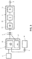
- the source (1) in question is characterized in that it incorporates, integrated in a single compact assembly, in addition to the input unit (3) and the power regulator (4) (which is the regulator or stage of the source responsible for handling high voltages and/or currents), a CPU microprocessor (10) and a PLC power line communication modem (11), said PLC modem (11) being connected to the input unit (3) which enables, upon detecting the zero crossing, communication with no noise on the network, for which said CPU microprocessor (10) is programmed to detect the quasi-resonant Q-R point and the input voltage zero crossing, as well as to calculate the output current combined with the correction of harmonics, determining that the source communicates with other sources at the time there is less noise on the network, and in turn stopping the generation of noise produced by the source itself.
- the source (1) in question consists of an electronic device which, integrated into the aforementioned compact assembly, includes as known elements:
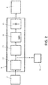
- Figure 2 shows in greater detail how the input unit (3), after the protection element (2), includes an electromagnetic interference EMI filter (12), after which the line is connected to the PLC modem (11), followed by a PFC (power factor controller) harmonics filter (13), followed by a bridge diode (14) and a capacitor (15) before its connection to the power regulator (4).
- an electromagnetic interference EMI filter (12) after which the line is connected to the PLC modem (11), followed by a PFC (power factor controller) harmonics filter (13), followed by a bridge diode (14) and a capacitor (15) before its connection to the power regulator (4).
- the power regulator (4) of the source incorporates transistors (16) which, with the transformer (5) interposed, connects with the CPU microprocessor (10), and recovery diodes (17), also interposing power transformers (5), connected to the output unit (6), a rectifier (18), after which an LCS filter is installed (19) (resonating circuit formed by an inductance coil with value L and a capacitor with capacitance C placed in series) and an electromagnetic interference (EMI) filter (12) is installed, and said filter is connected to the LEDs (8).
- LCS filter oscillated circuit formed by an inductance coil with value L and a capacitor with capacitance C placed in series
- EMI electromagnetic interference
- the most important characteristic of the power regulator in order to be able to attack [sic] LED diodes is that it should be a source of current and not voltage, and consequently must ensure that it functions in the so-called discontinuous "flyback" mode of power converters.
- the microprocessor will perform the appropriate calculations that make it work in that zone, and more specifically at the point in that zone in which the performance is at a maximum, the so-called Q-R or quasi-resonant point.
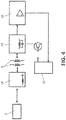
- Figure 4 shows how in the PLC modem (11), after the input unit (3), includes an LCS filter (19), transformer (5), an LCP filter (20) (resonant circuit formed by an inductance coil of value L and a capacitor with capacitance C placed in parallel) which connects to the CPU microprocessor (10) and an operational filter (22) which directly connects with the CPU microprocessor (10).
- LCS filter (19) transformer (5)
- LCP filter (20) resonance circuit formed by an inductance coil of value L and a capacitor with capacitance C placed in parallel
- an operational filter (22) which directly connects with the CPU microprocessor (10).
- FIG. 5 a diagram is observed of the detection of the Q-Resonant point (quasi-resonant) of the proposed power source (1), by means of the CPU microprocessor itself (10).
- the microprocessor detects point A at which the coil of the secondary power auxiliary ( Figure 1 , coil 23) crosses zero volts and adds to it the corresponding time at 90° of the sine wave (1/4 of the period) which is spontaneously formed when the secondary of the transformer (5) in Figure 1 has discharged all of the energy into the LEDs and reconnects the transistors at that point, called Q-R, where the losses in the transistor are minimal because of the lower voltage, and consequently the energy (1/2 C v 2 ) to be dissipated from the parasitic capacitor of the transistors is lower.
- An important novelty of this design is how said Q-R point is detected without thereby blocking all of the function of the microprocessor, and it consists of so doing from time to time because said Q-R point is moved very little.
- the Q-Resonant point is the point of maximum performance for a switched power source.
- the other known sources when they do so, do not do it with the CPU but rather with a specific dedicated integrated circuit.
- Figure 6 shows a diagram of the transmission or PLC modem (11), where it is observed how the source is shut off at zero crossings.
- the microprocessor controls the source as well as a transistor, a transformer and a circuit, with which it detects when the input voltage crosses zero and shuts off the source for an instant in order to emit pulses at the zero crossings of the input alternating voltage, also enabling the source to communicate with other sources, since at that time there is no noise on the network and all of the sources are shut off momentarily.
- figure 7 shows a diagram of the calculation of the output current and harmonics correction.
- the average output current to the LEDs is calculated from the peak value of the input voltage, measured directly from the input unit (3) and from the average value of the voltage at the LEDs (8), which is reflected in the power regulator by the auxiliary secondary of the power transformer ( Figure 1 , coil 23). In this way, different values of the average output current to the LEDs can be chosen without the need to be measuring it directly, thus saving costs.
- one quadrant of the input wave is divided into various points (8 in this example), in which the requested instantaneous current is modulated so that the result of the calculation of the waveform corresponds to the previously stated calculation relative to the "function of relative harmonics.”
- T ton 1 + vi n Vo
- Vp sen ( ⁇ ) the instantaneous input voltage as a function of the peak voltage Vp
- L the self-inductance of the primary of the transformer
- n is the transformation ratio
- Vo is the average output voltage (the LEDs (8)).
- the CPU (10) will be responsible for generating this variable connection time width of the transistors to ensure that the output current is the proper one and that the harmonics have the correct values.
- the CPU microprocessor (10) has a non-volatile memory that enables it to remember the on-time duration from the previous day and to make the necessary calculations to change the luminosity for each of up to 8 time intervals based on an extended dual level function, storing the definition of the time intervals in the CPU memory; and that the PLC modem (11) enables these parameters to be modified through powerline communication.
- the CPU microprocessor (10) by means of incorporated ADC (analog to digital) converters, enables measuring of the input voltage and activating the compatibility mode with a flux reducer present in the installation, reducing, from the 170 V input, the output current applied to the LEDs (8) proportionate to the input voltage.
- ADC analog to digital
Landscapes
- Engineering & Computer Science (AREA)
- Computer Networks & Wireless Communication (AREA)
- Signal Processing (AREA)
- Automation & Control Theory (AREA)
- Physics & Mathematics (AREA)
- Electromagnetism (AREA)
- Power Engineering (AREA)
- Cable Transmission Systems, Equalization Of Radio And Reduction Of Echo (AREA)
- Circuit Arrangement For Electric Light Sources In General (AREA)
Applications Claiming Priority (2)
| Application Number | Priority Date | Filing Date | Title |
|---|---|---|---|
| ES201430514A ES2528395B2 (es) | 2014-04-07 | 2014-04-07 | Fuente de alimentación inteligente, con comunicación digital a través de la línea eléctrica |
| PCT/ES2015/070247 WO2015155393A1 (es) | 2014-04-07 | 2015-03-31 | Fuente de alimentación inteligente, con comunicación digital a través de la línea eléctrica |
Publications (2)
| Publication Number | Publication Date |
|---|---|
| EP3145282A1 true EP3145282A1 (de) | 2017-03-22 |
| EP3145282A4 EP3145282A4 (de) | 2018-03-07 |
Family
ID=52441047
Family Applications (1)
| Application Number | Title | Priority Date | Filing Date |
|---|---|---|---|
| EP15776962.1A Withdrawn EP3145282A4 (de) | 2014-04-07 | 2015-03-31 | Intelligente stromquelle mit fähigkeit zur digitalen kommunikation über die stromleitung |
Country Status (4)
| Country | Link |
|---|---|
| US (1) | US20170026189A1 (de) |
| EP (1) | EP3145282A4 (de) |
| ES (1) | ES2528395B2 (de) |
| WO (1) | WO2015155393A1 (de) |
Families Citing this family (1)
| Publication number | Priority date | Publication date | Assignee | Title |
|---|---|---|---|---|
| CN119232202A (zh) * | 2023-06-28 | 2024-12-31 | 华为技术有限公司 | 通信方法、电源设备、通信设备、通信系统和电子芯片 |
Family Cites Families (9)
| Publication number | Priority date | Publication date | Assignee | Title |
|---|---|---|---|---|
| US8405488B1 (en) * | 2008-10-21 | 2013-03-26 | Universal Lighting Technologies, Inc. | System and method for encoding ballast control signals |
| US8390435B2 (en) * | 2009-08-07 | 2013-03-05 | General Electric Company | Apparatus for controlling integrated lighting ballasts in a series scheme |
| US9544975B2 (en) * | 2010-02-04 | 2017-01-10 | Ywire Technologies Inc. | Lighting control switch apparatus and system |
| US20150257211A1 (en) * | 2014-03-05 | 2015-09-10 | Cree, Inc. | Solid state lighting apparatuses and related methods |
| US9084333B2 (en) * | 2010-12-08 | 2015-07-14 | Devtech Pte Ltd. | System for monitoring and controlling high intensity discharge (HID) lamps |
| JP2013135509A (ja) * | 2011-12-26 | 2013-07-08 | Minebea Co Ltd | スイッチング電源装置および発光ダイオード照明装置 |
| US9736911B2 (en) * | 2012-01-17 | 2017-08-15 | Lutron Electronics Co. Inc. | Digital load control system providing power and communication via existing power wiring |
| US10285246B2 (en) * | 2014-02-17 | 2019-05-07 | Softkernel Co., Ltd. | Communication device using powerline and LED lighting system using the device |
| US9660542B2 (en) * | 2014-02-26 | 2017-05-23 | Infineon Technologies Austria Ag | Valley to valley switching in quasi-resonant mode for driver |
-
2014
- 2014-04-07 ES ES201430514A patent/ES2528395B2/es active Active
-
2015
- 2015-03-31 EP EP15776962.1A patent/EP3145282A4/de not_active Withdrawn
- 2015-03-31 US US15/302,316 patent/US20170026189A1/en not_active Abandoned
- 2015-03-31 WO PCT/ES2015/070247 patent/WO2015155393A1/es not_active Ceased
Also Published As
| Publication number | Publication date |
|---|---|
| ES2528395A1 (es) | 2015-02-09 |
| WO2015155393A1 (es) | 2015-10-15 |
| EP3145282A4 (de) | 2018-03-07 |
| ES2528395B2 (es) | 2015-08-13 |
| US20170026189A1 (en) | 2017-01-26 |
Similar Documents
| Publication | Publication Date | Title |
|---|---|---|
| Zhang et al. | A primary-side control scheme for high-power-factor LED driver with TRIAC dimming capability | |
| US6577512B2 (en) | Power supply for LEDs | |
| US8310172B2 (en) | Current ripple reduction circuit for LEDs | |
| CA2790890C (en) | Electrical systems | |
| TWI458247B (zh) | 返馳式控制器、返馳式轉換器及使用返馳式轉換器的調光器可控led電路 | |
| EP2515611B1 (de) | Lichtvorrichtung und Beleuchtungsvorrichtung | |
| RU2677865C2 (ru) | Лампа с радиочастотным (рч) управлением с совместимостью с регулятором яркости | |
| Moon et al. | Dimming-feedback control method for TRIAC dimmable LED drivers | |
| US20170223795A1 (en) | Digital Dimmable Driver | |
| KR101334042B1 (ko) | Led 조명 장치 및 그의 전류 레귤레이터와 전류 레귤레이팅 방법 | |
| US20120286696A1 (en) | Dimmable led lamp | |
| US20100213859A1 (en) | Adaptive Current Regulation for Solid State Lighting | |
| CN103533717B (zh) | 基于直流供电通信的电子设备及其控制方法 | |
| US9572209B2 (en) | LED actuating device and method | |
| US20120299511A1 (en) | Controlling the Light Output of One or More LEDs In Response to the Output of a Dimmer | |
| US20130193878A1 (en) | LED-Lighting System Comprising an Operational Data Memory | |
| TW201028041A (en) | Improved linearity in LED dimmer control | |
| TW201233248A (en) | Led driving apparatus and led lighting apparatus | |
| US20120139442A1 (en) | Mains Dimmable LED Driver Circuits | |
| KR20080011226A (ko) | 범용 라인 전압 디밍 방법 및 시스템 | |
| WO2023288095A1 (en) | Power supply device with over-power protection | |
| US7733035B2 (en) | Electronic power supply device for light-emitting diode | |
| US20140328415A1 (en) | Power factor correction for constant current input with power line communication | |
| EP2936934B1 (de) | Primärseitig gesteuerter konstantstromwandler für leuchtmittel | |
| Jane et al. | Dimmable light‐emitting diode driver with cascaded current regulator and voltage source |
Legal Events
| Date | Code | Title | Description |
|---|---|---|---|
| PUAI | Public reference made under article 153(3) epc to a published international application that has entered the european phase |
Free format text: ORIGINAL CODE: 0009012 |
|
| 17P | Request for examination filed |
Effective date: 20170130 |
|
| AK | Designated contracting states |
Kind code of ref document: A1 Designated state(s): AL AT BE BG CH CY CZ DE DK EE ES FI FR GB GR HR HU IE IS IT LI LT LU LV MC MK MT NL NO PL PT RO RS SE SI SK SM TR |
|
| AX | Request for extension of the european patent |
Extension state: BA ME |
|
| RIN1 | Information on inventor provided before grant (corrected) |
Inventor name: MOLERA PICAZO, JOSE VICENTE Inventor name: MONTORO IRADIER, AGUSTIN |
|
| DAV | Request for validation of the european patent (deleted) | ||
| DAX | Request for extension of the european patent (deleted) | ||
| A4 | Supplementary search report drawn up and despatched |
Effective date: 20180201 |
|
| RIC1 | Information provided on ipc code assigned before grant |
Ipc: H05B 33/08 20060101AFI20180126BHEP Ipc: H02M 7/02 20060101ALI20180126BHEP |
|
| STAA | Information on the status of an ep patent application or granted ep patent |
Free format text: STATUS: THE APPLICATION IS DEEMED TO BE WITHDRAWN |
|
| 18D | Application deemed to be withdrawn |
Effective date: 20180904 |